

Page 1

LSC Lighting Systems (Aust) Pty. Ltd.
ABN 21 090 801 675
Building 3, 66-74 Micro Circuit
Dandenong South, Victoria 3175 Australia
Tel: +61 3 9702 8000 Fax:+61 3 9702 8466
email: info@lsclighting.com
web: www.lsclighting.com
Wallmount Dimmer
INSTALLATION and OPERATION
Version V 1.3
Covering software Version 1.3
May 2013
Document number: RBW-T01U-A3
Page 2

DISCLAIMER
LSC Lighting Systems (Aust) Pty. Ltd. has a corporate policy of continuous improvement,
covering areas such as product design and documentation. To achieve this goal, we undertake
to release software updates for all products on a regular basis. In light of this policy, some
detail contained in this manual may not match the exact operation of your product. Information
contained in this manual is subject to change without notice.
In any event, LSC Lighting Systems (Aust) Pty. Ltd. cannot be held liable for any direct,
indirect, special, incidental, or consequential damages or loss whatsoever (including, without
limitation, damages for loss of profits, business interruption, or other pecuniary loss) arising
out the use or the inability to use this product for its intended purpose as expressed by the
manufacturer and in conjunction with this operating manual.
Servicing of this product is recommended to be carried out by LSC Lighting Systems (Aust) Pty.
Ltd. or its authorized service agents. No liability will be accepted whatsoever for any loss or
damage caused by service, maintenance or repair by unauthorized personnel.
In addition, servicing by unauthorized personnel may void your warranty.
LSC Lighting Systems’ products must only be used for the purpose for which they were
intended.
Page 3

Contents
Conventions Used in this Manual 1
1 Product Description 1
1.1 About this Manual ___________________ 1
1.2 Redback Overview __________________ 1
1.2.1 Features ___________________________ 1
1.2.2 Redback Control Philosophy ____________ 1
1.3 Models ___________________________ 2
1.4 Factory Fitted Options _______________ 2
1.4.1 Input RCD Protection _________________ 2
1.4.2 Dimming or Switching Outputs _________ 3
1.4.3 Output Connections __________________ 3
1.4.4 Neutral Disconnect Output MCB _________ 3
1.4.5 Inverted Controls ____________________ 3
1.4.6 100-120VAC Input Power______________ 4
1.4.7 3 Phase Delta Input Power _____________ 4
1.5 Optional Control Panels ______________ 4
1.5.1 Wallplates _________________________ 4
1.5.2 Panic Button ________________________ 4
1.6 Front Panel ________________________ 4
1.7 Touch Screen Control Panel ___________ 4
2 Installation 5
2.1 Safety ____________________________ 5
2.2 Unpacking _________________________ 5
2.3 Mounting the Redback _______________ 5
2.4 Patch Panels _______________________ 6
2.5 Inverted 24 Channel Redback _________ 6
2.6 Connections _______________________ 7
2.6.1 Input Power Supply __________________ 7
2.6.2 Cable Entry ________________________ 8
2.6.3 Connecting the Load Circuits ___________ 9
2.6.4 Connecting DMX512 __________________ 9
2.6.5 Wall Plate Connection _______________ 10
2.6.6 Panic Memory Connection ____________ 10
2.6.7 DMX Connector Plate - Option _________ 11
3 Configuring the Redback Wallmount
Dimmer 12
3.1 Control Source ____________________ 12
3.2 Patching _________________________ 12
3.3 Recording Memories ________________ 12
3.4 Optional Settings __________________ 12
4.9.1 Min Level _________________________ 27
4.9.2 Max Level ________________________ 27
4.9.3 Curve ___________________________ 27
4.9.4 Source ___________________________ 27
4.9.5 Default Channel Settings _____________ 27
4.10 Panic Menu _______________________ 28
4.10.1 Manually Setting Channel Levels _______ 28
4.10.2 Taking a Snapshot _________________ 29
4.10.3 Fade Time ________________________ 29
4.11 Colour Theme Menu ________________ 30
4.12 System Menu _____________________ 30
4.12.1 Wall Plate Setup ___________________ 30
4.12.2 Reset ____________________________ 30
4.12.3 Code Upgrade _____________________ 31
4.13 Lock / Unlock _____________________ 31
5 Wall Plates 33
5.1 Overview ________________________ 33
5.2 Installation _______________________ 33
5.2.1 RJ45 Connections __________________ 33
5.3 Wall Plate Installation: ______________ 34
5.3.1 Configuration _____________________ 34
5.3.2 Wallplate LED Colour Jumper Settings __ 34
5.3.3 Wallplate Mode Jumper Settings _______ 35
5.3.4 Wall Plates Setup Menu ______________ 36
5.3.5 Group ___________________________ 36
5.3.6 Link _____________________________ 37
6 Alarms and Troubleshooting 38
6.1 Maintenance ______________________ 38
6.2 Alarms __________________________ 38
6.3 Trouble Shooting __________________ 38
6.3.1 Rigger Test _______________________ 38
6.3.2 DMX Control ______________________ 38
6.3.3 Wallplate Control ___________________ 38
7 DMX Explained 39
7.1 Typical DMX Installations ____________ 39
8 RDM Explained 40
9 Specifications 41
10 Software Upgrade 42
4 Menu System 13
4.1 Overview ________________________ 13
4.2 Help Screens _____________________ 13
4.3 Home Pages ______________________ 13
4.3.1 Config ___________________________ 13
4.3.2 Status ___________________________ 13
4.4 Dimmer Output Home Page __________ 15
4.4.1 Riggers Control ____________________ 15
4.4.2 Chaser ___________________________ 16
4.5 DMX Address Home Pages ___________ 16
4.5.1 1 to 1 Patch _______________________ 17
4.6 Config Menu ______________________ 17
4.7 Memories Menu ___________________ 18
4.7.1 Create or Edit Memories _____________ 18
4.7.2 Playback Memories _________________ 20
4.8 DMX Menu _______________________ 20
4.8.1 DMX Patching ______________________ 20
4.8.2 DMX Loss Memory __________________ 22
4.8.3 Auto Power _______________________ 24
4.8.4 View Input ________________________ 25
4.9 Channels Menu ____________________ 25
11 Compliance Statements 43
11.1 CE Compliance Statement ___________ 43
11.2 C Tick Compliance Statement ________ 43
11.3 Product of Australia ________________ 43
12 Quick Reference 44
12.1 Home Pages ______________________ 44
12.2 Status ___________________________ 44
12.3 DMX Control ______________________ 44
12.3.1 DMX Patching _____________________ 44
12.3.2 DMX LOSS Memory _________________ 44
12.4 Memory Control ___________________ 45
12.4.1 Create or Edit Memories _____________ 45
12.4.2 Playback Memories _________________ 45
12.5 Auto Switch ______________________ 45
12.6 Auto Power _______________________ 45
12.7 Riggers Control____________________ 45
12.7.1 Chaser ___________________________ 45
Page 4

Conventions Used in this Manual
Throughout this manual, certain conventions have been used to make the meaning clearer.
A word in [Bold] text represents a button
Emphasis is indicated by underlining.
Notes or Hints are displayed in italic font
Copyright Notices
Redback Wallmount Dimmers are developed by LSC Lighting Systems (Aust) Pty. Ltd.
www.lsclighting.com
Copyright © 2013 LSC Lighting Systems (Aust) Pty. Ltd.
All rights reserved.
Contents of this manual, Copyright © 2013
Page 5

Redback Wallmount Dimmer
Product Description
Operator Manual V1.3
1 Product Description
1.1 ABOUT THIS MANUAL
This manual describes the installation, configuration and operation of the Redback
Wallmount range of slimline installation digital dimmers and wall plate stations
manufactured by LSC Lighting Systems.
There are four different colour themes that you can select on the LCD screen. This screen
images in this manual use the default “Redback” colour theme.
1.2 REDBACK OVERVIEW
The Redback Wallmount dimmers can be controlled by any DMX512 lighting controller or by
optional remote wall plate stations. Dimmer configuration, patching and local control is
achieved via a backlit colour touch screen on the front panel. A lock code can be used to
prevent unauthorised tampering. Most control functions, configuration options and front
panel operations can also be remotely controlled using the RDM (Remote Device
Management) protocol.
1.2.1 Features
DMX512 (1990), DMX512-A (E1-11) and RDM (E1-20) compliant control. If DMX is
lost, the Redback can either hold the last values or fade to a “DMX Loss” memory
after a programmable delay.
Optional switched power channel outputs provide direct power by utilising relays
guaranteeing there is absolutely no electronics in the circuit to interfere with
connected loads.
Six internal memories with wall plate control.
Panic mode for evacuation lighting.
Individual channel settings for:
o DMX address patching.
o Minimum and maximum output levels.
o Fade curve.
10 Amp MCB (Miniature Circuit Breaker) protection per channel.
100% duty cycle operation across all channels simultaneously.
Variable speed fan cooling. The fan only operates when required.
CE and C tick approved.
1.2.2 Redback Control Philosophy
The Redback Wallmount dimmer is known as an “ARCHI-TAINMENT” dimmer.
Architectural control of Redback memories is by remote “wall plates”.
Entertainment control is by DMX from your lighting controller.
The Redback Wallmount’s dimmer channels can be individually configured to be controlled
by either:
1. DMX Only
2. Memory Only
3. Auto Switch
4. Auto Power
1. DMX Only. When configured for “DMX Only”, a channel is controlled from a DMX lighting
controller. If DMX fails, the channels can either hold their last state or after a programmable
delay time, fade to a “DMX Loss Memory” previously stored in the Redback.
2. Memory Only. When configured for “Memory Only”, a channel is controlled from wall
plates that are used to recall memories (6) stored in the Redback dimmer. These memories
can also be recalled from the LCD touch screen.
3. Auto Switch. When configured for “Auto Switch” a channel will be automatically
switched from Memory to DMX control whenever the lighting controller is switched on (and
hence a DMX signal is detected on the input to the Redback).
Page 1
Page 6

Product Description
Redback Wallmount Dimmer
Operator Manual V1.3
6 channels
Internal terminal output option
shown
12 channels
UK output socket option shown
24 channels
GST18 output socket option shown
Auto Power
Presence of a DMX signal
switches channel to FULL ON
Individual
selection for
every Channel.
Presence of a DMX signal
switches channel to DMX Input
MEM/DMX
Switch
Memory Only
Auto Switch
DMX Only
DMX Input
Remote Control
from Wall plates
Redback
Channel
Memories
1 to 6
4. Auto Power. Channels configured for “Auto Power” are used to provide power to nondimmable fixtures whenever the lighting controller is switched on and hence a DMX signal is
detected on the input to the Redback. When “Auto Power” is enabled, channels configured
for “Auto Power” will be automatically switched ON at full level whenever any valid DMX
signal is detected. These channels will remain on for a programmable “hold time” when DMX
is no longer detected.
LSC recommends that fixtures requiring non-dimmed power should always be connected to
Redback channels fitted with the “Switch” output option. See section 1.4.2 for details.
The following diagram shows a simplified version of the control sources that can be chosen
for every channel.
1.3 MODELS
The Redback Wallmount range of dimmers is designed for permanent installation and is
available in either 6, 12 or 24 channels.
1.4 FACTORY FITTED OPTIONS
The Redback Wallmount dimmers can be supplied with the following factory fitted options:
1.4.1 Input RCD Protection
Redback’s can be supplied with an input RCD (Residual Current Device) breaker.
The 6 channel and 12 channel models are fitted with a single 3 phase 4 pole RCD.
The 24 channel models are fitted with a three 2 Pole RCD’s, one for each phase.
Page 2
Page 7

Redback Wallmount Dimmer
Product Description
Operator Manual V1.3
1.4.2 Dimming or Switching Outputs
Redbacks are constructed using internal modules that contain 6 channels each. Two types of
modules are available:
Dimmer modules.
Switch modules.
Redback’s can be therefore be ordered with combinations of dimming modules and
switching modules to provide a system with dimmed channels for conventional lighting and
non-dimmed (switched) channels for control of devices that require switched “non-dimmed”
power such as LED fixtures or moving lights.
For example, a Redback Wallmount 24 can be ordered with 18 channels of dimming and 6
channels of switched power.
To see the type of modules that are fitted to your Redback press the large status button at
the bottom of the LCD screen home page:
then from the Status menu that appears press [About].
The “About” screen shows the type modules that have been fitted to each group of 6
channels. They will be either an “Opto Dim Module” (dimmer) or a “Switch Module”
In this example, a 24 channel Redback is fitted as follows:
Channels 1 to 6 are Dimming outputs (Opto Dim Module).
Channels 7 to 12 are Dimming outputs (Opto Dim Module).
Channels 13 to 18 are Dimming outputs (Opto Dim Module).
Channels 19 to 24 are Switched outputs (Switch Module).
1.4.3 Output Connections
Redback’s can be supplied with either internal load connectors or front mounted load
sockets.
The following types of front mounted load socket are available:
Australian sockets.
U.K. 15A sockets.
Shuko sockets.
GST 18 sockets (Two x GST18 dimmed outputs and one GST18 non-dimmed output
per channel).
1.4.4 Neutral Disconnect Output MCB
Redback’s can be supplied with a “Neutral Disconnect” MCB for each output channel. This is
a MCB with a 2nd set of contacts to break the Neutral circuit (as well as the Active) when an
overload on the active causes the MCB to trip. It is not a two pole MCB, as these trip with
an overload on Active or Neutral.
1.4.5 Inverted Controls
The 24 channel Redback can be ordered with reversed labels and LCD screen for mounting
the opposite way up. This places the load connectors on the left of the dimmer which allows
it to be located to the right of a cable patch panel without the cables from the patch panel
running in front of the circuit breakers. A normal Redback 24 can be mounted on the other
side of the patch panel thus providing 24 channels on each side of the patch panel without
any patch cables hanging in front of the circuit breakers. See section 2.5.
Page 3
Page 8

Product Description
Redback Wallmount Dimmer
Operator Manual V1.3
Bank 1
Load Circuit
Breakers
Bank 2
Load Circuit
Breakers
Output
connectors
(optional).
Input RCD
(optional)
LCD Touch
Screen
Control Panel
? Help
1.4.6 100-120VAC Input Power
Redback’s can be supplied for 100-120VAC input power operation.
1.4.7 3 Phase Delta Input Power
Redback’s can be supplied wired for 3 phase Delta input power operation.
1.5 OPTIONAL CONTROL PANELS
1.5.1 Wallplates
Wall plates are optional remote control switch plates that can be used to control any of the
6 internal memories that are stored in the Redback. Wall plates are available with either 1,
2 or 6 buttons.
1.5.2 Panic Button
Panic buttons are available to control the “Panic/Evacuation” lighting memory in the
Redback. They use a push button to activate and a key switch to de-activate.
1.6 FRONT PANEL
The front panel contains the input RCD (Residual Current Device) breaker (optional), load
MCB (Miniature Circuit Breakers), and LCD touch screen. Depending upon your model of
Redback, load circuits are either plugged into the output connectors or hard wired to the
internal load connectors.
12 channel Redback fitted with UK output sockets
1.7 TOUCH SCREEN CONTROL PANEL
The Redback Wallmount dimmer uses a colour LCD touch screen which is operated by
touching the virtual buttons and faders with your finger or a stylus.
The “Dimmer Output” home page shows the channel levels.
Many menus have Help screens available. Press the [?] button (when available) to see the
help screen. For example:
Pressing [?] shows……
Press anywhere within the help screen to cancel.
Page 4
Page 9

Redback Wallmount Dimmer
Installation
Operator Manual V1.3
Keyhole
mounting
point
Keyhole
mounting
point
2 Installation
2.1 SAFETY
All electrical work must be carried out by suitably qualified persons.
The Redback Wallmount dimmer is primarily designed for mounting on a solid flat vertical
surface.
The dimmer is heavy. Use the correct lifting procedures when handling the dimmer.
2.2 UNPACKING
The Redback Wallmount dimmer is fully tested and inspected before leaving the factory.
Upon delivery, inspect the dimmer for signs of damage or mishandling. In the event of any
damage, contact your LSC agent.
2.3 MOUNTING THE REDBACK
The Redback Wallmount dimmer is designed for wall mounting and is provided with keyhole
cut-outs in 4 locations, two at the top and two at the bottom. A mounting template is
provided with unit.
Ensure that the mounting can support the weight. Refer to the specifications at the end of
this manual for the weight of your model.
The ventilation holes at the top, bottom and front of the unit must be kept clear. When
mounting multiple dimmers, allow a minimum space of 100mm between dimmers and
200mm above and below each dimmer. Refer to the diagram below for recommended
spacing between dimmers and fixed obstacles.
Page 5
Page 10

Installation
Redback Wallmount Dimmer
Operator Manual V1.3
Normal 24 channel Redback
Patch Panel
Reversed 24 channel Redback
2.4 PATCH PANELS
Optional LSC Patch Panels may be mounted beside the dimmers allowing flexibility in load
connection. The Patch Panels are usually mounted to the right of the dimmer so that the
patch leads do not hang in front of the circuit breakers and LCD screen.
2.5 INVERTED 24 CHANNEL REDBACK
The 24 channel Redback Wallmount can be ordered with the load connectors on the left of
the dimmer which allows it to be located to the right of a cable patch panel. A normal
Redback 24 can be mounted on the left of the patch panel thus providing 48 channels of
dimming without any patch cables hanging in front of the circuit breakers or control panels.
Page 6
Page 11

Redback Wallmount Dimmer
Installation
Operator Manual V1.3
Cable entry
plate.
Load
Connectors
Supply
Connectors
Cable entry
plate.
Control
Connectors
2.6 CONNECTIONS
Connections are provided behind the front covers for power input, DMX control, Wallplate
control, Panic control and load power. All control circuit wiring should be isolated from the
power cabling by a metal conduit run up to the control circuit connectors.
12 channel Redback with front covers removed.
2.6.1 Input Power Supply
The Redback Wallmount dimmer system must be fed from a suitable external circuit
breaker. The optional RCD input breaker provides Residual Current Protection only. It does
not protect the input circuit from current overloads. The current ratings of the supply for
each model are listed below.
Note: The rating of the Neutral conductor feeding the dimmer must be at least 1.25 times
that of rated limit of any of the Active phase conductors.
This is because various combinations of dimmer drive will result in a Neutral current higher
than the line current due to the phase control characteristics of these type of dimmers.
For example, a 40Amp 3 phase supply must have a neutral rated at 50Amps.
The input power connection utilizes five 35mm2 terminals (3 phases, neutral and earth).
The nominal input voltage is 220-240 Volts. 3-phase Star (380-415V). 50-60Hz.
3 phase Delta is also available as a factory option.
2.6.1.1 6 Channel Redbacks
6 Channel Redbacks can be powered from:
Three phase supply of nominal 220-240VAC* at 50 - 60Hz of up to 20 Amps per
phase. See Neutral rating note above.
Single phase supply of nominal or 220-240VAC* at 50 - 60Hz of up to 60 Amps
2.6.1.2 12 channel Redbacks
12 channel Redback can be powered from:
Three phase supply of nominal or 220-240VAC* at 50 - 60Hz of up to 40 Amps per
phase. See Neutral rating note above.
Single phase supply of nominal or 220-240VAC* at 50 - 60Hz of up to 120 Amps.
Page 7
Page 12

Installation
Redback Wallmount Dimmer
Operator Manual V1.3
Duct entry plate
with cable
knock out.
No user
access from
this plate
2.6.1.3 24 channel Redbacks
24 channel Redback can be powered from:
Three phase supply of nominal or 220-240VACv at 50 - 60Hz of up to 80 Amps per
phase. See Neutral rating note above.
Single phase supply of nominal or 220-240VAC* at 50 - 60Hz of up to 120 Amps.
The input power connectors are limited to 120 Amps so it is imperative that the
single phase supply is current is also limited to 120 Amps.
*100-120VAC versions are available by special order from the factory.
Safety Note: Conversion between three phase and single phase operation should only be
undertaken by a suitably trained and qualified electrical technician.
2.6.2 Cable Entry
Redback Wallmount dimmers are fitted with removable cable duct plates on the top right
and bottom right of the unit.
The bottom plate is provided with a cable knock-out entry. To remove the knock-out insert
a flat blade screwdriver in the slot provided and twist out the metal disk and fit a M32 cable
gland.
Page 8
Page 13

Redback Wallmount Dimmer
Installation
Operator Manual V1.3
Australian Outlets
GST Outlets
Earths for
Channels 1 to 6
Earths for
Channels 7 to 12
Channel 1 Active
Channel 1 Neutral
2.6.3 Connecting the Load Circuits
Models with internally connected load circuits are provided with numbered 6mm terminals
for Active (A) and Neutral (N) for each load circuit. One 16mm Earth (E) terminal is
provided for every 6 load connections. These connections are wired directly to the outlets at
the required locations in the building.
Models with front mounted outlets have numbers indicating their channel.
Redbacks fitted with GST outlets have 2 DIMMING (or optionally switched) outlets and one
HOT POWER outlet per channel. The dimming and hot power outlets of each channel are all
connected to the channels load circuit breaker. The total load per channel must not exceed
10 amps.
2.6.4 Connecting DMX512
DMX 512 is the industry standard for the transmission of digital control signals between
lighting equipment. DMX is usually “looped” from one piece of equipment to the next.
See “DMX Explained and Typical Installations” for more information.
DMX 512 is connected to the Redback Wallmount dimmer by using the screw terminals
inside the unit. The DMX512 connection is high impedance. This allows the DMX512 to be
wired in parallel to other dimmers. If the DMX line ends at this dimmer (is not looped to
other dimmers or devices) then the DMX TERM switch must be set to TERM.
Page 9
Page 14

Installation
Redback Wallmount Dimmer
Operator Manual V1.3
DMX
terminals.
DMX
terminate
switch.
Wall plate
RJ45
connector
Wall plate
RJ45
connector
Panic
terminals.
LSC recommends the use of RS485 data cable or shielded CAT5 cable for the DMX
connections. Audio or Microphone cables must not be used.
Connections:
COM (common) = Pin 1 of a 5 Pin XLR connector.
DMX- (Data negative) = Pin 2 of a 5 Pin XLR connector.
DMX+ (Data Positive) =Pin 3 of a 5 Pin XLR connector.
2.6.5 Wall Plate Connection
Wall plates are the remote wall switches for the Redback Wallmount dimmers. The wall
plates allow you to recall any of the 6 internal memories from the Redback for replay at a
pre-programmed level and fade time. Wall plates are available with either 1, 2 or 6 buttons.
Wall plates are connected to the Redback via RJ45 connectors and cat5 cable. Wall plates
require all 8 wires in the CAT5 cable to be connected. Two parallel connectors are provided
to simplify cable runs to different locations.
See section 5 for details on Wallplate installation and configuration.
2.6.6 Panic Memory Connection
The “Panic” function provides emergency evacuation lighting that can be easily recalled by
either a simple “Panic” or “Evacuate” button or it can be connected to a BMS (Building
Management System) so that it is automatically operated when a fire alarm is activated.
The “Panic” connection recalls a “Panic Memory” that you have created in the Redback. This
memory will typically contain channel levels that will provide suitable lighting for evacuation
purposes.
The Panic (Fire Panel) button function uses two connections, one to activate panic and one
for release. Both connections use screw terminals and share the common connection.
The Panic button terminals are labelled:
FP ACT (Fire Panel Activate)
FP REL (Fire Panel Release)
FP COM (Fire Panel Common)
A momentary contact closure between FP ACT and FP COM will activate the Panic memory.
A momentary contact closure between FP REL and FP COM will release the Panic memory.
Specialised “FIRE/Panic” panels are available from LSC or your LSC agent. These use a
press button to activate the panic memory and a keys-switch to de-activate the memory.
See section 4.10 for details on how to program the “Panic” memory.
Page 10
Page 15

Redback Wallmount Dimmer
Installation
Operator Manual V1.3
Internal wiring and cable routing. Left hand cover
panel removed to show cable routing. Leave in
place to avoid damage to static sensitive control
electronics.
DMX cable connection detail
2.6.7 DMX Connector Plate - Option
The Optional Redback wall mount dimmer DMX input plate is designed to fit all Redback wall
mount series dimmers. The Redback Wall-mount Dimmer has four blanking or cable access
plates to suit different installation requirements—one access opening in each corner of the
dimmer on the upper or lower end plate. The DMX input plate may be fitted to any access
opening as long as there is sufficient room and clearance from high voltage mains cabling
within the dimmer.
The DMX input plate provides DMX In and Thru connectivity with no buffering between the
connectors. The DMX Input plate does not terminate the DMX cable in any way.
Termination should be provided by setting the internal “DMX Term” switch.
This kit is supplied with:
1.. DMX connectors on circuit board and mounted on a metal cover plate.
2.. Connection cable—with 6 way connector at one end and 3 stripped wires at the other.
Installation
1.. Remove the existing blanking plate and fit the DMX
input plate using the two black screws as shown. Note
that the picture below show the left hand cover panel
removed—this is for illustration purposes only to show
cable routing. LSC recommends this left hand cover panel
is not removed.
2.. Ensure cabling inside the dimmer is clear of the
internal electronics and other HV cabling. Secure cabling
to the chassis using cable ties or cable tie blocks.
3.. Wire the stripped ends of the cable into the DMX connector block as shown. Ensure
the cabling is connected as follows:
DMX+ (XLR Pin 3) >> Red wire
DMX— (XLR Pin 2) >> White Wire
COM (XLR Pin 1) >> Black Wire
Page 11
Page 16

Configuration
Redback Wallmount Dimmer
Operator Manual V1.3
3 Configuring the Redback Wallmount Dimmer
When a Redback Wallmount dimmer is installed, it needs to be configured to suit its
particular installation and application. This involves the following operations which are
achieved via the touch screen menus. The menu system is fully described in the next
section.
3.1 CONTROL SOURCE
Each channel needs to configured for the “Control Source” that will control it. This could be
either “DMX Only”, “Memory Only”, “Auto SWITCH” (switch from Memory to DMX control
whenever the lighting controller is switched on and hence a DMX signal is detected on the
input to the Redback) or “Auto Power” (switch to full ON whenever the lighting controller is
switched on and hence a DMX signal is detected on the input to the Redback). See section
1.2.2 for more information on these choices.
The default setting is for channels to “Auto Switch”.
See Control Source in section 4.9.
3.2 PATCHING
Channels set to DMX or Auto Switch Mode, may need to be patched to the DMX slot number
that is to control them.
See DMX Patching in section 4.8.
3.3 RECORDING MEMORIES
Channels set to Memory Only or Auto Switch are controlled by the (6) memories in each
Redback. These memories must be created and saved in the Redback. You can create
memories by setting channel levels on the touch screen or by taking a snapshot of the DMX
input or current output of the Redback.
See Recording Memories in section 4.7.
The Wall plates must also be connected and configured to control the required memories.
See section 2.6.5 and section 5.
3.4 OPTIONAL SETTINGS
In addition to these settings you can also set the following optional parameters;
Create a DMX memory that can be automatically recalled when the DMX signal is
lost. See section 4.8.2
Create a “Panic” memory that will be recalled when the remote “Panic” button is
pressed. See section 4.10
Set minimum and maximum levels for each channel.
See section 4.9
Set each dimmer to either “S Curve” (dimmer) or “Non Dim” (switch between OFF or
fully ON). See section 4.9.3
Set a “lock code” to prevent unauthorised access to the menu system. See section
4.13
Page 12
Page 17

Redback Wallmount Dimmer
Menu System
Operator Manual V1.3
? Help
Menu name
4 Menu System
4.1 OVERVIEW
The Redback Wallmount dimmer uses a colour LCD touch screen which is operated by
touching the virtual buttons or faders with your finger or a stylus. The menus on the screen
provide the functions to configure and operate the dimmer.
4.2 HELP SCREENS
Many menus have Help screens available. Press the [?] button to see the help screen.
Touch anywhere within the help screen to cancel.
4.3 HOME PAGES
There are two possible “home” pages that you can select to suit your individual
requirements. The “Dimmer Output” home page shows the current output of the Redback
and the “DMX Address” home page has a large DMX address display.
“Dimmer Output” Home Page
Pressing [DMX Address] changes the display to show the “DMX Address” home page.
Pressing [View Output] on the “DMX Address” home page changes back to the “Dimmer
Output” home page.
Both home pages are described in detail later in this section.
Both home pages have two common buttons at the bottom of the screen, the large
[Status] button and the [Config] button beside it.
4.3.1 Config
Pressing [Config] allows you to access a range of functions and setups via sub-menus. Each
sub-menu screen has it name in the top left corner. The menus are fully described later in
this section. If the Redback has been “locked”, the [Config] button is replaced by the
[Padlock] button. Touching the [Padlock] button and entering your code number unlocks
the Redback and reveals the [Config] button.
4.3.2 Status
The information on the large [Status] button shows the status of
the Redback memories, input power, DMX and temperature.
The top line indicates which memories are active on the output.
1 to 6 are the six internal (wall plate) memories.
D is the “DMX loss” memory.
P is the “Panic button” memory.
Blue is active. Grey is not active.
A shows the status of the “Auto on” (when DMX is present) function.
Green is active. Grey is not active (DMX not present) and the “A” is not shown when
“Auto on” has been disabled.
Page 13
Page 18

Menu System
Redback Wallmount Dimmer
Operator Manual V1.3
The bottom line indicates:
P1, P2, P3 show the presence of the input power phases.
Flashing Red is not present.
DMX shows the presence of a DMX control signal.
Flashing Red is not present.
TRM indicates that the DMX line is terminated by the internal “DMX TERM” switch.
The internal temperature of the Redback is shown in degrees Celsius.
Pressing the status button reveals the detailed “Dimmer Status”.
It shows the presence of the input power phases, DMX presence, position of the DMX
termination switch, dimmer running time, last cause of a reset and the individual
temperatures of the internal modules of the Redback.
Pressing [About] shows the software versions and the type of power modules (Firing
boards).
Redbacks are constructed using internal power modules that contain 6 channels each. Two
types of power modules are available:
Dimmer modules.
Switch modules.
Redback’s can be therefore be ordered with combinations of dimming modules and
switching modules to provide a system with dimmed channels for conventional lighting and
non-dimmed (switched) channels for control of devices that require “non-dimmed” power
such as LED fixtures or moving lights.
For example, in the menu above, there are 18 channels of dimming and 6 channels of
switched power.
Page 14
Page 19

Redback Wallmount Dimmer
Menu System
Operator Manual V1.3
Channel level
bargraphs.
Shows status
and selects
“Status” menu
Selects
“Configuration”
menu
Selects “DMX
Address” home
menu
Selects
“Riggers
Control” menu
DMX Address
(when 1to1
patched)
Help
Dot shows
“Minimum” level
set for a channel.
Dot shows
“Maximum” level
set for a channel.
4.4 DIMMER OUTPUT HOME PAGE
The “Dimmer Output” home page shows current level of each channel in a bar graph display
which is colour coded to show the current control source for each channel.
“Dimmer Output” Home Page.
The bargraph shows the output level of every channel. Channels can be controlled from
multiple sources and the colour code of the bargraph indicates the source of the control
signal.
Green = controlled by DMX
Blue = controlled by a Memory.
Red = controlled locally by either the Riggers Control or a “minimum level” channel
setting if DMX is not present.
In the above example, channels 12, 16 and 17 are controlled by a Memory and the large
status button shows you that it is Memory 1 (it is blue).
Channels are controlled on a HTP (highest Takes Precedence) basis. If multiple sources are
controlling a channel (such as DMX and Riggers control) then the highest level will be output
and will hence determine the colour of the bargarph. If a minimum or maximum level has
been set for a channel they are indicated by dots on the channels bargraph.
The top right corner of the screen shows the DMX address information.
If a 1 to 1 patch is implemented it shows the DMX addresses of the first and last
channels of the dimmer rack.
If channels are individually patched it shows the word “Patched”.
Pressing [Riggers Control] allows you to control Redback channels directly from the touch
screen as described below.
Pressing [DMX Address] selects the “DMX Address” home page as described below.
4.4.1 Riggers Control
To set the level of a channel(s) (or run a chaser) from the touch screen, select the “Dimmer
Output” home page (above) then press [Riggers Control].
Page 15
Page 20

Menu System
Redback Wallmount Dimmer
Operator Manual V1.3
Dimmer
output
Output levels.
Channels under
Riggers Control
shown in red.
Non-dim
channel
DMX
address of
first dimmer
channel
DMX
address of
last dimmer
channel
The output of the Riggers Controls can be turned off or on by pressing
[De activate]/[Activate].
To set the level of a channel(s), use the virtual faders. “Non-dim” channels have an On/Off
push button switch instead of a fader. The button turns green when it is on.
Press [‹] or [›] to select more channels (if fitted).
When finished press [Exit].
4.4.2 Chaser
To activate the chaser, from the “Rigger Control” (above), press [Chaser].
To enable the Chaser press [Activate].
Select a pattern” using the 6 “Chase Pattern” buttons.
Set the speed in BPM (Beats Per Minute) by pressing the [] or [] buttons.
Use the “Direction” buttons to select [l>>> l] (forward), [l<<< l] (reverse) or [l< > l] (bounce
from end to end).
To disable the Chaser press [De-Activate].
When finished press [Exit].
4.5 DMX ADDRESS HOME PAGES
The “DMX Address” home page has two formats:
If a 1 to 1 patch is implemented it shows the DMX addresses of the first and last channels of
the dimmer (in a large and small font respectively).
If channels are individually patched it shows the word “Patched” and the DMX addresses of
all channels in the dimmer.
Page 16
1 to 1 Patch
Page 21

Redback Wallmount Dimmer
Menu System
Operator Manual V1.3
Dimmer
output
DMX address of
every dimmer
channel
Channels individually patched
Both displays also show a colour coded mini bar-graph of the dimmer output at the top of
the screen. See the “Dimmer Output” home page above for the colour code.
Pressing [1 to 1 Patch] allows you to easily patch all of the channels to sequential DMX
slots as described below.
Pressing [View Output] selects the “Dimmer Output” home page.
4.5.1 1 to 1 Patch
Patches are often performed in contiguous blocks of addresses. The 1 to 1 patch function
provides a rapid method of patching all of the dimmers in one Redback rack to sequential
DMX slots, starting from a DMX address that you enter.
To perform a 1 to 1 patch, select the “DMX Address” home page (above) then press [1 to 1
Patch].
Enter the DMX address for the first channel in this Redback then press [Apply].
Individual channel patching is performed in the DMX menu as described below.
4.6 CONFIG MENU
From any of the “Home Pages”, pressing [Config] reveals the “Configuration Menu”.
The buttons on the “Configuration Menu” provide access to the Sub-Menus and functions
which are described in detail on the following pages. Each sub menu has its name at the top
of its screen.
The following table shows the functions that can be performed in each sub menu.
Page 17
Page 22

Menu System
Redback Wallmount Dimmer
Operator Manual V1.3
Memories
DMX
Panic
Edit Wallplate Memories 1-6
Patch
Edit Panic Memory
Fade In/Out selected
memory
View DMX Input levels
Fade In/Out Panic memory
Edit DMX Loss Memory &
Delay Time
Fade In/Out DMX Loss
memory
Enable Auto Power
Auto Power Hold Time
Channels
Colour
Theme
System
Min Level
Antarctic
Wallplate Setup
Max Level
Dawn
Code Upgrade
Curve
Redback
Reset
Source
Gothic
Memory Number
Fade In/Out time
in seconds
Bargraph of
channel levels in
the memory
White = Inactive
Config Menu Structure
4.7 MEMORIES MENU
Selecting [Config] [Memories] provides menus for editing and activating the dimmer’s 6
memories. You can create memories by setting channel levels on the touch screen or by
taking a snapshot of the DMX input or current output of the Redback. The memories are
saved in the Redback and are recalled using the buttons on external wallplates or directly
from the Redback touch screen.
When a channels “source” is set to “Memory Only”, it is always controlled by the
Redback memories.
When a channels “source” is set to “Auto Switch”, it is controlled by the Redback
memories only when there is no DMX signal present at the Redback.
See section 4.9 for details on how to set a channels “control source”.
4.7.1 Create or Edit Memories
To Create or edit a memory, from either home screen press [Config], [Memories].
Each memory button shows a bargarph display of the contents of that memory and also its
fade time in seconds. The colour of the bar at the bottom of the bargraph shows the status
of the memory: White = Inactive, Red = Fading (in or out) and Green = Active.
Page 18
Page 23

Redback Wallmount Dimmer
Menu System
Operator Manual V1.3
Navigator shows
current group of 6
selected channels
highlighted
Selects next group
of 6 channels (if
fitted)
Memory Button
Touch a memory to select it. The currently selected memory is highlighted.
Press [Fade In]/[Fade Out] to see the selected memory on the output of the
Redback.
Press [Edit] to edit the selected memory. You can either take a [Snap] (snapshot)
of the current DMX input signal or the current state of the Redback’s Outputs or
select a channel(s) and manually set their levels using the controls on the screen.
4.7.1.1 Manually Setting Channel Levels
The “Memory Setup” menu (above) shows the first 6 channels. Use the [<] or [>] buttons
to see the other groups of 6 channels (if fitted). The navigator at the top right of the screen
shows current group of 6 selected channels highlighted.
Touch a channel to select it. You can select multiple channels. To select a range of channels
select your first channel then press [Thru] then your last channel. Use [All] to select all
channels. Press [None] to de-select all channels.
When you have selected your channel(s) press [Level].
Use the keypad to set the level then press [Apply].
To create a memory by taking a snapshot, press [Snap] from the “Memory Setup” menu
above.
Pressing [DMX] will take a snapshot of the current DMX input signal.
Pressing [Outputs] will take a snapshot of the current output of the Redback. These
channel levels could be coming from DMX, Memories, Riggers Control or a combination of
all three.
4.7.1.2 Taking a Snapshot
Page 19
Page 24

Menu System
Redback Wallmount Dimmer
Operator Manual V1.3
Channel levels in
the snapshot
When you take the snap, the channels levels will be displayed in the box below the memory
number.
To save the snapshot to the memory press [Apply].
The channels levels that were captured in the snapshot can be edited by manually setting
channel levels as described above.
4.7.1.3 Fade Time
When editing a memory (above), you can set a fade time for the memory by pressing
[Fade].
Enter a time in seconds (0 to 99.99) then press [Apply].
When all of the channel levels and the fade time of the memory are correct, press [Exit].
4.7.2 Playback Memories
To playback a memory either;
Press [Config] [Memories]. Select a memory by touching it, then press
[Fade In]/[Fade Out].
Use a Wallplate button that has been programmed to control that memory number.
See section 4.12.1 Wallplate Setup for details on how to program Wallplate buttons.
4.8 DMX MENU
Selecting [Config] [DMX] provides menus for:
Patching DMX.
Editing and activating the DMX Loss (D) memory.
Enabling and time setting the Auto Power function.
Viewing the Input DMX signal.
The patch allows you to patch (connect) DMX slots (addresses) from your DMX lighting
controller to Redback channel numbers. Each Redback dimmer unit numbers its channels
Page 20
4.8.1 DMX Patching
Page 25
Redback Wallmount Dimmer
Menu System
Operator Manual V1.3
Channel
DMX Slot
1
24
2
25
3
26
10
27
from channel 1 through to channel 6 or 12 or 24, depending upon the quantity of channels
in the model of Redback.
Patches are required when;
A particular DMX slot number from the lighting controller is to control an Redback
dimmer with a different channel number.
A single DMX slot number is to control multiple Redback channel numbers.
Patches are often performed in contiguous blocks of addresses. The 1 to 1 patch function
provides a rapid method of patching all of the dimmers in one Redback frame to sequential
DMX slots, starting from a DMX address that you select.
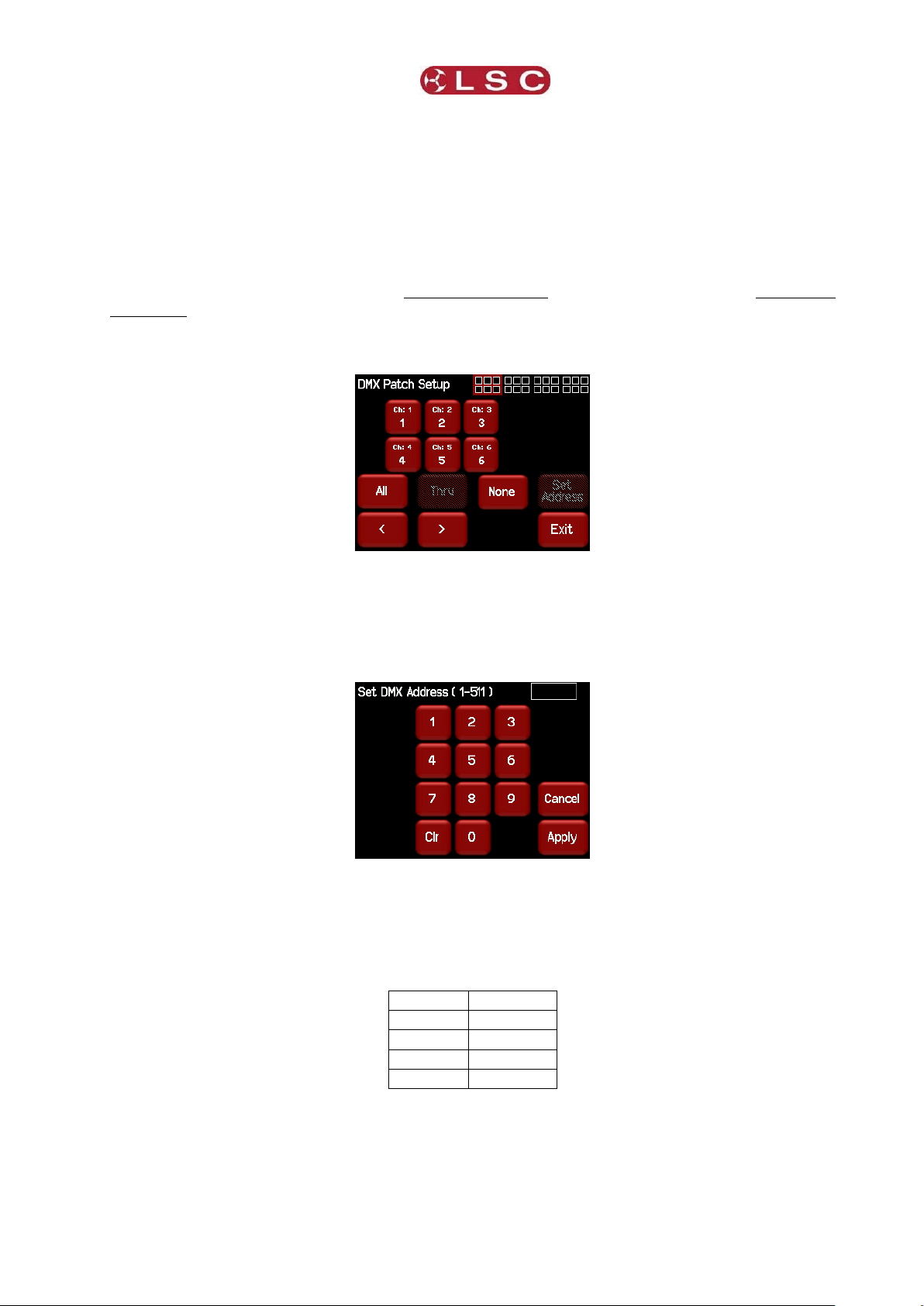
To individually patch dimmers channels to DMX addresses press [Config] [DMX] [Patch].
The menu shows the first 6 channels. Use the [<] or [>] buttons to see the other groups of
6 channels (if fitted). Touch a channel to select it. You can select multiple channels. To
select a range of channels select your first channel then press [Thru] then your last
channel. Use [All] to select all channels. Press [None] to de-select all channels.
When you have selected your channel(s) press [Set Address].
Enter the required DMX address then press [Apply].
If more than one channel is selected, then the lowest channel number will be patched to the
selected DMX slot and the following dimmers will be patched to the sequential DMX slot
numbers.
For example, if channels 1,2, 3 and 10 are selected and DMX slot number 24 is applied the
result will be ……
To patch multiple channels to the same DMX slot patch them one at a time.
When finished patching press [Exit].
To perform a 1 to 1 patch, from the “DMX Address” home page press [ 1 to 1 Patch], enter
the starting address for the Redback then press [Apply].
Page 21
Page 26

Menu System
Redback Wallmount Dimmer
Operator Manual V1.3
Selects next group
of 6 channels (if
fitted)
Navigator shows
current group of 6
selected channels
highlighted
4.8.2 DMX Loss Memory
The Redback has a “DMX Loss Memory” that you can program. In the event that the DMX
input signal is lost, channels set to DMX control will hold their last DMX level for a
programmable “Delay” time. The default setting for this time is “Infinite”. If you set a delay
time other than “Infinite”, the channels will fade to the “DMX Loss Memory” when the delay
time expires (up to 1 hour). When DMX is restored, the Redback will fade back to the DMX
signal.
To create or edit a “DMX Loss” memory press [Config] [DMX].
The “DMX Loss Memory” box has 3 buttons:
Press [Delay] to set the “Delay” time as described above.
Press [D] to create or edit the memory as described below.
Press [Fade In]/[Fade Out] to see the DMX Loss memory on the output.
The “D” button shows a bargarph display of the current DMX Loss memory and also its fade
time in seconds. When you press [D], you can either take a [Snap] (snapshot) of the
current DMX input signal or the current state of the Redback’s Outputs or select a
channel(s) and manually set their levels using the controls on the screen.
The “DMX Loss Memory” menu (above) shows the first 6 channels. Use the [<] or [>]
buttons to see the other groups of 6 channels (if fitted). The navigator at the top right of
the screen shows current group of 6 selected channels highlighted.
Touch a channel to select it. You can select multiple channels. To select a range of channels
select your first channel then press [Thru] then your last channel. Use [All] to select all
channels. Press [None] to de-select all channels. When you have selected your channel(s)
press [Level].
Page 22
4.8.2.1 Manually Setting Channel Levels
Page 27

Redback Wallmount Dimmer
Menu System
Operator Manual V1.3
Channel levels in
the snapshot
Use the keypad to set the level then press [Apply].
4.8.2.2 Taking a Snapshot
To create a memory by taking a snapshot, press [Snap] from the “DMX Loss Memory”
menu above.
Pressing [DMX] will take a snapshot of the current DMX input signal.
Pressing [Outputs] will take a snapshot of the current output of the Redback. These
channel levels could be coming from DMX, Memories, Riggers Control or a combination of
all three.
When you take the snap, the channels levels will be displayed in the box.
To save the snapshot to the memory press [Apply].
The channels levels that were captured in the snapshot can be edited by manually setting
channel levels as described above.
When editing the DMX Loss memory (above), you can set a fade time for the memory by
pressing [Fade].
Enter a time in seconds (0 to 99.99) then press [Apply].
4.8.2.3 Fade Time
Page 23
Page 28

Menu System
Redback Wallmount Dimmer
Operator Manual V1.3
Dimmed
Power
DMX
DMX
Non-dimmed Power
Lighting
Controller
Redback
Dimmer
DMX Splitter
4.8.3 Auto Power
Many lighting fixtures such as LED’s and moving fixtures require a constant source of non
dimmed power when they are operating. Normally you would manually switch on the power
to these devices prior to a show and manually switch them off at the conclusion. Auto Power
is a feature that automatically switches selected Redback channels to full ON whenever
there is a DMX signal present on the input to the Redback and switches them OFF when the
lighting controller is turned off.
A “Hold Time” can be set to prevent fixtures being turned off if there is a short interruption
to the DMX signal and also to allow for a cool down period for the fixtures.
In the following example, the 3 moving fixtures require non-dimmed power plus DMX for
control. They are connected to a Redback “Switch” channel that is configured for “Auto
Power”. The 2 conventional fixtures are connected to Redback dimmer outputs. When the
lighting controller is switched on, the Redback detects the DMX signal and automatically
switches on the moving fixtures.
LSC recommends that fixtures requiring non-dimmed power should always be connected to
Redback channels fitted with the “Switch” output option. See section 1.4.2 for details.
Note: To make a channel switch On when DMX is present you must “Enable” Auto Power as
described below and also select “Auto Power” as the channel’s “Control Source”. This is
selected in the “Control Source” section of the “Channels” menu. See the “Channels Menu”
below for details.
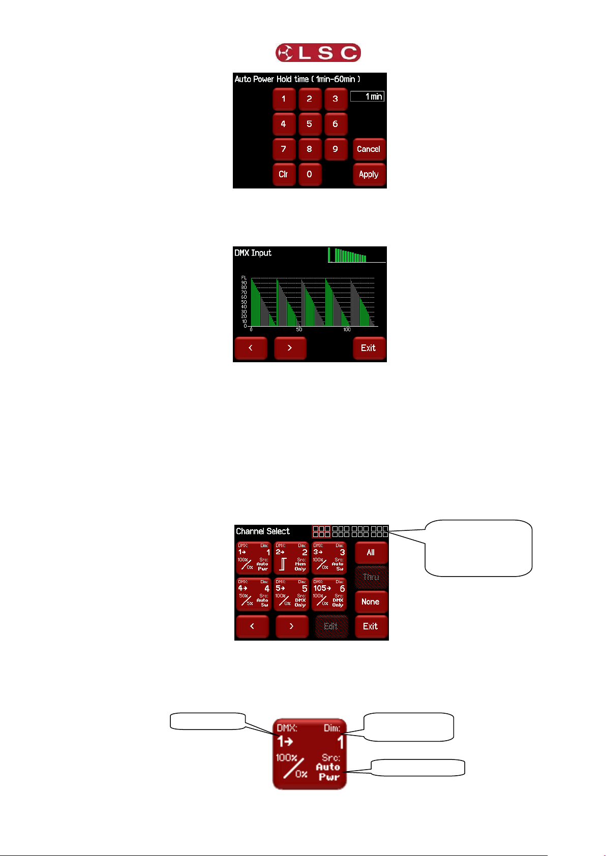
To select the DMX Setup menu, press [Config] [DMX].
The “Auto Power” box has 2 buttons:
Press [Disable] to disable the Auto Power function. The button then changes to
[Enable]. This is a global setting for all channels that have their control source set to
“Auto Power”
Press [Hold Time] and enter a time from 1 to 60 minutes. This is the time that the
“Auto Power” channels will stay ON when the DMX signal is lost.
Page 24
Page 29
Redback Wallmount Dimmer
Menu System
Operator Manual V1.3
DMX Address
Channel Output
Number
Control Source
Navigator shows
current group of 6
selected channels
highlighted
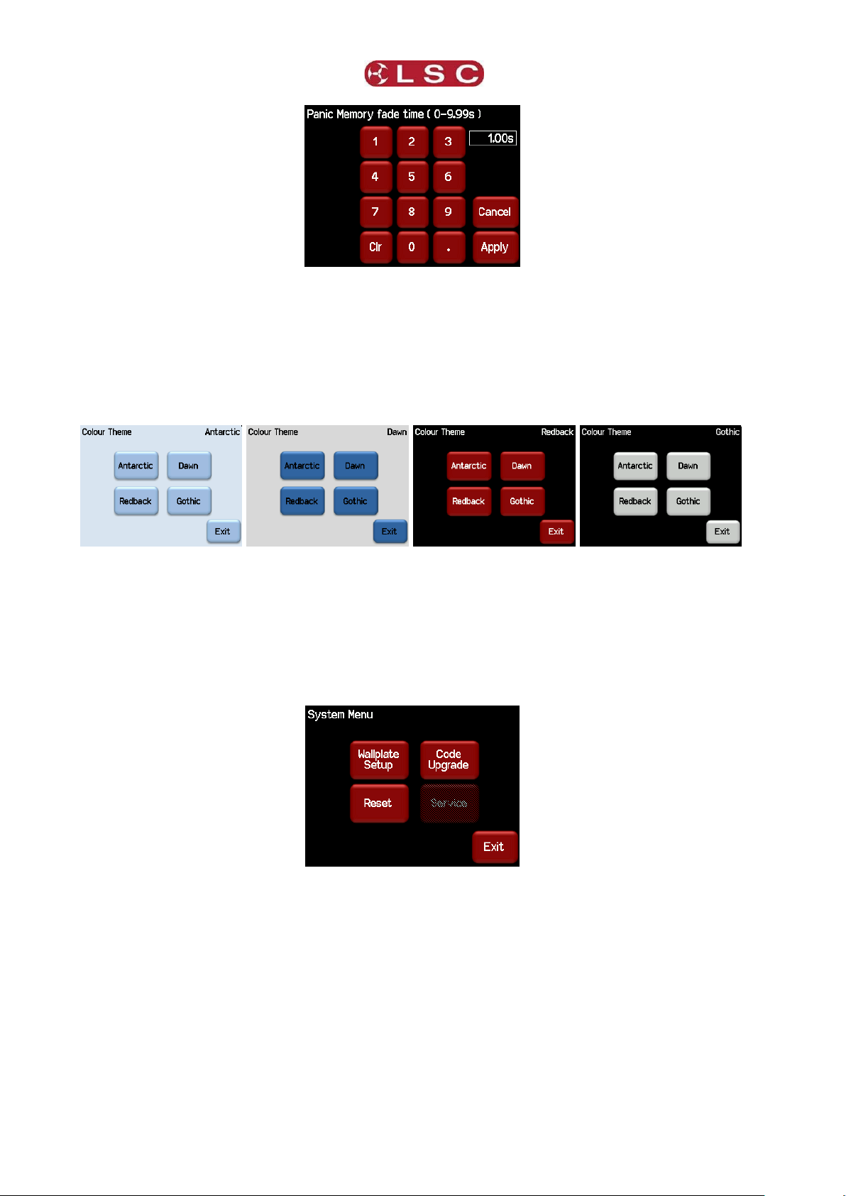
4.8.4 View Input
The “DMX Setup” menu allows you to view the channel levels on the DMX input. Press
[View Input]
Press either [>] or [>] to scroll through all slots in the DMX Universe.
4.9 CHANNELS MENU
Selecting [Config] [Channels] provides menus for configuring the following parameters for
each channel:
Min. Minimum Level
Max. Maximum Level
Curve. Diming or Non Diming.
Source. The control source for the channel. The choices are: DMX only, Memory only,
Auto Switch (between Memory and DMX whenever DMX is present) and Auto Power
(On at full whenever DMX is present).
The screen shows the settings for the first 6 channels. Use the [<] or [>] buttons to see the
other groups of 6 channels (if fitted). The navigator in the top right of the screen shows the
selected group highlighted.
Each channel button shows the settings for that channel.
Page 25
Page 30

Menu System
Redback Wallmount Dimmer
Operator Manual V1.3
Min Level
Max level
Curve
Source
Max =50%
Min = 5%
Curve = Non-Dim
Curve =Dim
Dimmer Channel 6
patched to DMX 105
Selected
Channel
Selected
Channels
Parameter
Selector
Parameter
Selector
Help
Selected
Parameter
To change the settings of a channel(s), select the channel(s) by touching. You can select
multiple channels. To select a range of channels select your first channel then press [Thru]
then your last channel. Use the [<] or [>] buttons to see the other groups of 6 channels (if
fitted). Use [All] to select all channels. Press [None] to de-select all channels.
The selected channels are highlighted in the navigator:
In this example channels 1 through 6 plus channel 20 are selected.
When you have selected your channel(s) press [Edit].
There are 4 possible parameter menus: Min Level, Max level, Curve and Source. Use the
[] and [] “Parameter Selector” buttons to scroll through the parameter settings for the
selected channel(s).
Channels fitted with “Switch Modules” only have the “NonDim” curve available.
Page 26
Page 31

Redback Wallmount Dimmer
Menu System
Operator Manual V1.3
ATTRIBUTE
DEFAULT SETTING
Min Level
0%
Max Level
100%
Fade Curve
S Curve
Control Source
Auto Switch
If a channel is set to “NonDim” then the Min and Max settings are not available and any Min
or Max settings that may have been made are ignored.
Each parameter setting is described below and on screen “Help” also explains each
parameter.
4.9.1 Min Level
“Min” sets the level of the channel output when the control signal is set to minimum. For
example, setting this value slightly above zero is useful to “Pre-Heat” lamp filaments.
4.9.2 Max Level
“Max” sets the level of the dimmer output when its control signal is set to maximum. For
example, setting this value to 90% will extend the life of a lamp as it never operates on full
voltage or setting it to 50% provides 115volt output
4.9.3 Curve
Fade Curve is the curve or “transfer characteristic” between input control signal and dimmer
output. The following curves are available;
S Law
Non Dim
When a channel is set to “Non Dim”, the channel will switch from OFF to full ON when the
control signal is raised above 60% and when the level drops below 40%, the channel will
switch OFF. “Non Dim” is used for devices that do not fade, but need to be switched OFF or
ON such as motors or discharge lamps. Min and Max level are not available when Non Dim
is selected.
4.9.4 Source
The Redback channels can be individually configured to be controlled by either:
DMX only. When configured for “DMX Only” a channel is controlled from a DMX
lighting controller.
Memory only. When configured for “Memory Only” a channel is controlled from wall
plates that are used to recall memories (6) stored in the Redback dimmer. These
memories can also be recalled from the LCD touch screen.
Auto Switch. Whenever a valid DMX signal is connected to the Redback, channels
set to “Auto Switch” will be automatically switched from Memory control to DMX
control. When the DMX signal is lost, they will automatically revert to Memory
control.
Auto Power. Channels configured for “Auto Power” are used to provide power to
non-dimmable fixtures whenever the lighting controller is switched on (and hence a
DMX signal is detected on the input to the Redback). When “Auto Power” is enabled,
channels configured for “Auto Power” will be automatically switched ON at full level
whenever any valid DMX signal is detected. These channels will remain on for a
programmable “hold time” when DMX is no longer detected.
LSC recommends that fixtures requiring non-dimmed power should always be
connected to Redback channels fitted with the “Switch” output option. See section
1.4.2 for details.
4.9.5 Default Channel Settings
The default settings for channel parameters are;
Page 27
Page 32

Menu System
Redback Wallmount Dimmer
Operator Manual V1.3
Navigator shows
current group of 6
selected channels
highlighted
Selects next group
of 6 channels (if
fitted)
4.10 PANIC MENU
The “Panic” function provides emergency evacuation lighting that can be easily recalled by
either a simple “Panic” or “Evacuate” button or it can be connected to a BMS (Building
Management System) so that it is automatically operated when a fire alarm is activated.
The “Panic” input is a dry contact closure that stops all current output and replaces it with a
“Panic Memory” that you have created in the Redback. This memory will typically contain
channel levels that will provide suitable lighting for evacuation purposes. A separate contact
closure is required to release the panic memory. When Panic has been activated , “Panic
Memory Active” flashes on the screen.
See the “Installation” section for details on how to connect the Panic and Release buttons.
Selecting [Config] [Panic] provides menus for:
Creating, editing the Panic Memory (P).
Activating the Panic Memory for testing purposes.
The “P” button shows a bargarph display of the current Panic memory and also its fade time
in seconds.
Pressing the [P] button allows you to create or edit the memory.
You can either take a [Snap] (snapshot) of the current DMX input signal or the current
state of the Redback’s Outputs or select a channel(s) and manually set their levels using the
controls on the screen.
4.10.1 Manually Setting Channel Levels
The “Panic Memory Setup” menu (above) shows the first 6 channels. Use the [<] or [>]
buttons to see the other groups of 6 channels (if fitted). The navigator at the top right of
the screen shows current group of 6 selected channels highlighted.
The default setting for the Panic memory is for all dimmer channels at an intensity of 65%
and all non dim channels set to ON.
Page 28
Page 33

Redback Wallmount Dimmer
Menu System
Operator Manual V1.3
Channel levels in
the snapshot
Touch a channel to select it. You can select multiple channels. To select a range of channels
select your first channel then press [Thru] then your last channel. Use [All] to select all
channels. Press [None] to de-select all channels.
When you have selected your channel(s) press [Level].
Use the keypad to set the level then press [Apply].
4.10.2 Taking a Snapshot
To create a “Panic” memory by taking a snapshot, press [Snap] from the “Panic Memory”
menu above.
Pressing [DMX] will take a snapshot of the current DMX input signal.
Pressing [Outputs] will take a snapshot of the current output of the Redback. These
channel levels could be coming from DMX, Memories, Riggers Control or a combination of
all three.
When you take the snap, the channels levels will be displayed in the box below the memory
name.
To save the snapshot to the memory press [Apply].
The channels levels that were captured in the snapshot can be edited by manually setting
channel levels as described above.
4.10.3 Fade Time
When editing the Panic memory (above), you can set a fade time for the memory by
pressing [Fade].
Page 29
Page 34
Menu System
Redback Wallmount Dimmer
Operator Manual V1.3
Enter a time in seconds (0 to 9.99) then press [Apply].
See the “Installation” section for details on how to connect a “Panic” button.
4.11 COLOUR THEME MENU
Selecting [Config] [Colour Theme] provides menus for changing the colour of the display.
The choices are:
4.12 SYSTEM MENU
Selecting [Config] [System] provides menus for the following functions:
Wall plate Setup.
Reset.
Code Upgrade.
Service. (Factory use only).
4.12.1 Wall Plate Setup
The “Wall plate Setup” menu provides functions for configuring the operation of wall plate
switches connected to the Redback dimmer. Wall plates are used to control any of the 6
lighting memories that you have stored in the Redback. Jumpers inside each wall plate allow
you to configure them so that any of the buttons can control any of the 6 memories.
See the “Installation” section for details on how to connect wall plates to the Redback.
See section 5 “Wall Plates” for details on how to configure wall plate operation.
The Redback provides two different types of reset function.
Page 30
4.12.2 Reset
Page 35

Redback Wallmount Dimmer
Menu System
Operator Manual V1.3
Lock/Unlock
.
4.12.2.1 Restart Dimmer
In the unlikely event that the Redback fails to respond, the operating system may be
restarted so that the software may initialise and recommence normal operation. Performing
a restart will not affect any of the settings or memory.
4.12.2.2 RESET To Defaults
This will ERASE all memory from the Redback and reset to defaults.
4.12.3 Code Upgrade
See section 10 for details.
4.13 LOCK / UNLOCK
To lock the touch screen of the Redback and prevent unauthorised access press [Config].
Pressing the “Padlock” symbol provides 3 levels of lock.
User. Locks out the “Config”, “Riggers Control” and “1 to 1 Patch” menus.
Config. Locks out the “Config” menus.
System. Locks out the “System” menu.
Note: The “System” menu is used for factory setup and has no user functions. It is always
locked.
Pressing a [Lock] button reveals a “Lock” keypad. Enter a four digit code and the [Lock]
button appears.
Page 31
Page 36

Menu System
Redback Wallmount Dimmer
Operator Manual V1.3
Locked
Press [Lock] to lock the selected level.
If “User” or “Config” are locked, the [Config] button is replaced by a [Padlock] symbol.
To unlock, press the [Padlock] symbol and enter your 4 digit code.
Page 32
Page 37

Redback Wallmount Dimmer
Wall Plates
Operator Manual V1.3
6 Button Australian Format
UK Format Wall Plates
Pin Number
Function
1
Control Line 1
2
Control Line 2
3
Control Line 3
4
+ V Power
5
Control Line 5
6
Control Line 6
7
Control Line 7
8
Ground
Redback
Wallmount
Dimmer
Wallplate
Wallplate
Wallplate
5 Wall Plates
5.1 OVERVIEW
Wall plates are optional remote control switch plates that can be used to control any of the
6 internal memories that are stored in the Redback. Memories are recorded (or edited) from
the Redback’s LCD touch screen. Memories are recalled from wall plates or from the LCD
touch screen.
Wall plates are available with either 1, 2 or 6 buttons. Each button has a LED indicator
which always glows dimly. The LED will flash when its memory is fading up or down and is
bright when its memory is active. The colour of the LED can be selected by jumpers inside
the wallplate.
5.2 INSTALLATION
Wall plates are connected to the Redback Wallmount dimmer using CAT5 cable. All
connections are via industry standard RJ45 connectors. Wall plates require all 8 wires in the
CAT5 cable to be connected. Two wires are used for power and 6 wires for the control
signals. The Redback and the wallplates have 2 RJ45 connectors allowing the cable to be
daisy chained from plate to plate.
5.2.1 RJ45 Connections
Page 33
Page 38

Wall Plates
Redback Wallmount Dimmer
Operator Manual V1.3
5.3 WALL PLATE INSTALLATION:
Up to 5 Wall plates may be connected to a Redback wallmount dimmer. Additionally the
connecting Cat x cable length should not exceed 150 metres. The category of cable used
(Cat5, Cat6 or Cat7) is not relevant in this type of installation.
There are four steps required for correct configuration of the Redback Wall plates.
1.. Labelling:
Each button may be labelled. Included with the Redback Wall plate is a sheet of
pre-printed labels numbered 1 thru 6. Cut out the required labels. Carefully unscrew the
circuit board from the front panel and snap off the clear button caps. Place the labels
5.3.1 Configuration
inside the caps and refit the caps. Ensure the labels are oriented correctly.
If you require custom labels, please visit the LSC website or the Redback Wallmount
Dimmer Operator Manual CD to download a template that allows custom labels to be
created and printed onto transparency medium.
2.. Colour:
Set the desired colour for the buttons. Refer to the LED colour table below. Note that there
must be a colour selected or there will be no indication on the Redback Wall plate at all.
When a memory is not active there will be a very dull glow of the buttons, this may not be
visible under daylight conditions. When a memory is active the button glows at a higher
intensity to show a memory is active. The button LED will flash while a memory is fading.
3.. Mode:
Set the mode of the Redback Wall plate buttons using the information over the page.
4.. Memory Setup:
Configure the Redback Wall plate memories in the memories setup menu in the Redback
Wallmount Dimmer. Refer section 6.3.2 of the Redback Wallmount Operator Manual for
more information.
The colour of the LEDs within the Button
Indicators may be changed to Blue, Green
5.3.2 Wallplate LED Colour Jumper Settings
or Red by setting one pin jumper.
Any combination of these colours may be
made by combining two or even all three
colours with the extra pin jumpers.
The Red Bar shows a connected jumper.
Page 34
Page 39

Redback Wallmount Dimmer
Wall Plates
Operator Manual V1.3
5.3.3 Wallplate Mode Jumper Settings
Mode setting connects the Redback Wall plate buttons to the Redback Wallmount dimmer
memories. The diagrams below depict the Redback Wall plate options with the control
memory number shown inside the circle. From the diagrams below, locate the drawing
which shows the required memory / button configuration and set the Mode jumpers
accordingly.
Note the settings below are the only valid configurations.
A mode must be set for the plate to operate correctly.
Buttons on different wall plates may be connected to the same control line so that the same
memory can be controlled from several locations.
Page 35
Page 40

Wall Plates
Redback Wallmount Dimmer
Operator Manual V1.3
Control line
number
Memory
Number
5.3.4 Wall Plates Setup Menu
The default configuration of the “Wall Plates Setup” menu is for buttons 1 to 6 to “Toggle”
memories 1 to 6 ON or OFF. Therefore, press a button to fade up its memory. Press it again
to fade it down.
For example, pressing button 1 on a wall plate (with default button jumpers) would fade up
memory 1. Pressing it again would fade it down.
Selecting [Config] [System] [Wall plate Setup] reveals the “Wall Plates Setup” menu:
This menu allows you to group and link buttons and then change their functions as
described below.
5.3.5 Group
Adjacent buttons can be grouped (or un-grouped) by selecting them and clicking [Group].
For example, a 2 button group and a 4 button group could be configured as follows:
Buttons in a group can be configured as either “Toggle”, “ Inc” or “ Dec”.
“ Inc” or “ Dec” buttons are usually configured in groups that contain 3 or more buttons.
One or more buttons in the group are set as “Toggle” and they control their relevant
memory(s). The “ Inc” or “ Dec” buttons in the group then allow you to control (raise or
lower) all the active (faded up) memories in the same group.
Each press of a Dec button on a wall plate will decrease the intensities of the
ACTIVE memory(s) in the group by 5%.
Each press of a Inc button on a wall plate will increase the intensities of the
ACTIVE memory(s) in the group by 5%.
To configure a button as “ Inc” or “ Dec”, there must be a “Toggle” button in the same
group. Select a button in the group then press either [ Inc] or [ Dec].
For example, buttons 5 and 6 have been configured as Inc and Dec:
Page 36
Page 41

Redback Wallmount Dimmer
Wall Plates
Operator Manual V1.3
Therefore, in the example above, pressing the button for control line 3 will fade up memory
3. Pressing the button for 6 will decrease all of the channel levels in memory 3 by 5%. Press
it again for another 5% decrease. Presses of the button for 5 will fade memory 3 back up.
Note: With this configuration, memories 5 and 6 are no longer available.
5.3.6 Link
Adjacent “toggle” buttons within a group can be linked (or un-linked) by selecting them and
clicking [Link].
A Linked button ACTIVATES its memory and DEACTIVATES all other memories to which it
has been linked.
For example, buttons 1 and 2 have been linked.
Pressing control line 1 will fade up memory 1.
Pressing control line 2 will fade up memory 2 AND fade down memory 1.
Pressing control line 1 again will fade up memory 1 AND fade down memory 2.
In the following example, a 6 button wall plate controls 6 memories and only the latest
memory to be pressed will be active.
Page 37
Page 42

Alarms & Troubleshooting
Redback Wallmount Dimmer
Operator Manual V1.0
6 Alarms and Troubleshooting
Warning. No user controls or user serviceable parts are located inside the Redback
Wallmount Dimmer. Refer all servicing to suitably qualified personnel.
6.1 MAINTENANCE
Ensure that the air vents at the top, bottom and front of the frame are free from dust.
Check that all connector screw terminal are tight. This must be performed by a suitably
qualified person.
Check that the Redback contains the latest software release.
6.2 ALARMS
The [Status] button at the bottom of the LCD “Home Screens” indicates the following:
P1, P2, P3 show the presence of the input power phases. Flashing Red is not
present.
DMX shows the presence of a DMX control signal. Flashing Red is not present.
Temperature. There is a separate temperature sensor for each bank of 6 dimmers.
The display shows the highest temperature from all of the sensors. If the
temperature of the Redback Wallmount is too high, the temperature display on the
LCD will flash Red and ALL OUTPUT from the Redback is automatically switched OFF.
Either reduce the load or increase the cooling to reduce the temperature. When the
temperature returns to normal, the Redback automatically returns to normal
operation.
6.3 TROUBLE SHOOTING
If a channel is not working check the MCB (Miniature Circuit Breaker) for that channel.
If the MCB has tripped (OFF), firstly try to determine the cause of the breaker tripping. It
could be a blown lamp or a circuit overload. Rectify to problem (replace the lamp or reduce
the load) then restore the MCB. If the MCB continues to trip, refer the problem to a suitably
qualified person.
6.3.1 Rigger Test
You can test the operation of a dimmer channel from the “Riggers Control” on the LCD
touch screen. See section 4.4.1.
6.3.2 DMX Control
If the dimmer is working from the Riggers Control but not via DMX, check that the dimmer
is patched to the correct DMX slot and correctly configured for DMX control. See sections
4.8 and 4.9.4
6.3.3 Wallplate Control
If the dimmer is working from the Riggers Control but not via Wallplate memories:
Check that the dimmer is correctly configured for Memory control. See section 4.9.4
Test the memory by fading it in using the LCD touch screen. See section 4.7.2.
Check that the Wallplate is connected and correctly configured. See section 5.
Page 38
Page 43

Redback Wallmount Dimmer
DMX Explained
Operator Manual V1.0
DMX
Cable
Redback
DMX Slots
61-66
Redback
DMX Slots
49-60
Redback
DMX Slots
25-48
Redback
DMX Slots
1-24
Lighting
Controller
Termination
Switch set
to TERM
7 DMX Explained
DMX512/1990-A is the industry standard for the transmission of digital control signals
between lighting equipment. It utilises just a single pair of wires on which is transmitted the
level information for the control of up to 512 DMX slots (addresses or channels).
The information for each slot is sent sequentially. The level of slot 1 is transmitted, then the
level of slot 2, then 3, etc. up to a maximum of 512 slots. This stream of data containing
the levels for all 512 DMX slots is repeated a minimum (generally) of 44 times per second.
This provides sufficient updates of channel information for smooth fade transitions.
As the DMX512-A signal contains the level information for all slots, each piece of equipment
needs to be able to read the level(s) of the slots(s) that apply only to that piece of
equipment. To enable this, the Redback dimmer has a “DMX Patch” menu that allows you to
patch (connect) each DMX slot (address) from your lighting controller to a Redback channel
number or to multiple channel numbers.
When good quality data cables are used, DMX512 cable runs may be up to 1,000 metres in
length. When several DMX feeds are required (to feed different locations), DMX512 splitters
must be used. These provides multiple isolated DMX512 feeds.
The Redback uses a high impedance DMX input circuit allowing you to loop the DMX signal
from one Redback to the next. The last Redback in the chain must have the “DMX Terminate
switch” set to TERM to terminate the line.
Note: Do not use unscreened microphone or low speed data cables for DMX. This can cause
problems in the DMX network. Make sure the cable conforms to the EIA485 cable
requirements by providing the following specifications:
Low capacitance
One or more twisted pairs
Foil and braid shielded
Impedance of 85 -150 Ohms, nominally 120 Ohms
22AWG gauge for continuous lengths over 300 metres
7.1 TYPICAL DMX INSTALLATIONS
In the following example, the DMX output signal from the lighting control desk is fed to the
DMX connector of the first Redback dimmer. The DMX cable is then looped to the following
Redback dimmers. The order of the daisy chaining is not important as each Redback
channel can be patched to any DMX slot number. The end of the DMX line is terminated to
prevent the signal reflecting back up the line and causing possible errors.
Page 39
Page 44

Specifications
Redback Wallmount Dimmer
Operator Manual V1.3
8 RDM Explained
RDM stands for Remote Device Management. It is an “extension” to DMX.
Since the inception of DMX it has always been a ‘one way' control system. Data only ever
flows in one direction, from the lighting controller outwards to whatever it may be
connected to. The controller has no idea what it is connected to, or even if what it's
connected to is working, switched on, or even there at all!
RDM changes all that allowing the equipment to answer back!
An RDM enabled moving light, for example, can tell you many useful things about its
operation - the DMX address it is set to, the operating mode it is in, whether its pan or tilt is
inverted and how many hours since the lamp was last changed.
But RDM can do more than that. It isn't limited to just reporting back, it can change things
as well. As its name suggests, it can remotely manage your device.
LSC’s Redback Dimmer range are RDM enabled products. This allows you to use RDM to
interrogate the dimmer to find out its status and also to set its DMX address, soft patch it,
and a host of other functions.
RDM has been designed to work with existing DMX systems. It does this by interleaving its
messages with the regular DMX signal over the same wires. There is no need to change any
of your cables but because RDM messages now go in two directions, any in-line DMX
processing you have needs to be changed for new RDM hardware. This will most commonly
mean that DMX splitters and buffers will need to be upgraded to RDM capable devices.
To utilise RDM you will also need an RDM controller. Presently these are devices that plug in
to the DMX line and talk the RDM language. They put the messages on to the DMX line,
listen for any replies and display the results via an attached computer. The latest lighting
consoles now also come with RDM controllers built in.
RDM also has the ability to read and report operating statistics and error conditions from
any enabled equipment that supports it. This opens up the possibility of remotely
monitoring the condition of your lighting rig and getting notice of failed equipment or even
advanced notice of things that may be cause for concern. For example, a moving light that
reports a very high bulkhead temperature may be suffering from a failed fan or clogged
filter or a scroller that reports a high motor current may have a jammed scroll.
Page 40
Page 45
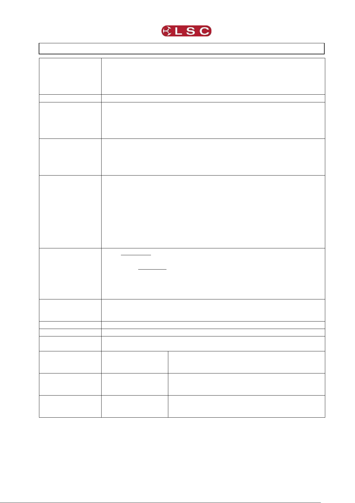
Redback Wallmount Dimmer
RDM Explained
Operator Manual V1.3
Power Input
Nominal: 220-240 Volts.
3-phase star (380-415V). 50-60Hz
(Single phase operation possible. See section 2.6.1)
Operating range : Typically 190-260V, 45-65Hz
3-phase delta connection is available as a factory fitted option.
Power Connection
Five 35mm2 terminals.
Control Inputs
DMX512 (1990) or DMX512-A (E1-11) and RDM (E1-20) via 3-pin
screw terminals.
Wall plate control via RJ45 connections. (Wall plates available
separately)
Panic input via 3-pin screw terminals.
Power Modules
Two standard types of power modules are available:
6-channels of dimming and 6 channels of relay control.
These modules may be mixed and matched to provide a system with
dimmed channels for conventional lighting and non-dimmed (relay)
channels for control of LED fixtures or moving lights.
Outputs
Standard screw terminals provided. One 4mm2 for each output circuit
plus one 16mm2 neutral terminal and one 16mm2 earth terminal for
each group of 6 circuits.
Several types of output panels can be ordered:
6 x 3 pin Australian sockets.
6 x 3 pin UK 15A sockets.
6 x channels of GST18 3-pin socket patch providing 2 x GST18
dimmed outputs and one GST18 Hot Power (non-dimmed) per
channel.
Load Output per
Channel
10A maximum load per channel, protected by 6kA rated thermal
magnetic miniature circuit breaker (MCB).
25 watts minimum load per channel to provide reliable dimming
operation.
LSC’s proprietary Current Control Technology © (CCT) protects all
MCBs from nuisance tripping due to cold lamp inrush currents.
Optional RCD
protection
Three single breakers for 24-channel model and one 3-phase unit for 6
and
12-channel models.
Duty Cycle
Rated at 100% across all channels simultaneously at 25°C ambient.
Construction
Aluminium housing and zinc steel panels and polycarbonate labels.
Mounting
The unit is wall mounted utilising keyhole cut-outs in 4 locations.
A mounting template is provided with the unit.
Dimensions and
weights
6 channel dimmer
Dimensions: 47 x 43 x 12cm
Box dimensions: 48 x 45 x 15cm
Packed weight: 9kgs
12 channel dimmer
Dimensions: 69 x 43 x 12cm
Box dimensions: 70 x 45 x 15cm
Packed weight: 15kgs
24 channel dimmer
Dimensions: 104 x 43 x 12cm
Box dimensions: 105 x 45 x 15cm
Packed weight: 28kgs
9 Specifications
Page 41
Page 46

Software Upgrade
Redback Wallmount Dimmer
Operator Manual V1.0
SD card
slot.
10 Software Upgrade
LSC Lighting Systems has a corporate policy of continuous improvement to its products. The
Redback Wallmount dimmer software (firmware) is subject to this policy as new features are
added and existing features improved.
The software version of your Redback Wallmount dimmer can be checked by pressing
[Menu] [Options] [About].
To upgrade your Redback Wallmount software, download the latest version from the LSC
web site, www.lsclighting.com, unzip it and save the new software to an SD Card. Both HC and
low density format cards are supported. The file will be called “RBW_V*.bin” where * is the
version number.
Press [Menu], [Setup], [Code Upgrade].
Remove the front connector or blanking panel and insert the SD card.
Follow the onscreen instructions.
Page 42
Page 47

Redback Wallmount Dimmer
Compliance Statements
Operator Manual V1.0
11 Compliance Statements
11.1 CE COMPLIANCE STATEMENT
The Redback Dimmer from LSC Lighting Systems (Aust) Pty. Ltd. has been designed and
tested to the European Committee for Electrotechnical Standardization (CENELEC) standard–
EN55022 (Information Technology Equipment).
11.2 C TICK COMPLIANCE STATEMENT
All LSC products with CE Compliance automatically comply with C-Tick requirements as per
Section 182 of the Radio-communications Act 1992. LSC Company Registration number is
N921.
11.3 PRODUCT OF AUSTRALIA
The Redback Wallmount dimmer meets the requirement status “Product of Australia” as
defined by the Australian Governments Trade Practise Act 1974, Section 65AC and
administered by the Australian Made Campaign Limited (AMCL). All LSC manufactured products
have virtually all of their design, production and manufacture processes occur in Australia, thus
qualifying for the highest status by the AMCL.
Page 43
Page 48

Quick Reference Redback Wallmount Dimmer
Operator Manual V1.3
“DMX Address” with 1 to 1 Patch.
“DMX Address” with Individual Patches.
12 Quick Reference
12.1 HOME PAGES
The “Dimmer Output” home page shows the channel levels.
This home page accesses the [Riggers Control] and the [Config] menus.
Press [DMX Address] to change to the home “DMX Address” home page.
The “DMX Address” home page shows the DMX patch numbers and has two possible formats
depending upon the DMX patch:
This home page accesses the [1 to 1 Patch] and the [Config] menus.
Press [View Output] to change to the “Dimmer Output” home page.
12.2 STATUS
The large [Status] button shows the status of the Memories, input power phases, DMX and
temperature of the Redback.
Press the [?] button on the “Dimmer Output” home page to see legend for the [Status] button.
Touch anywhere within the help screen to cancel.
12.3 DMX CONTROL
To set a channel(s) to “DMX Only” control press; [Config] [Channels].
Select the required channel(s) then press [Edit].
Repeatedly press or to select the “Source” parameter.
Press [DMX Only] [Apply] [Exit].
12.3.1 DMX Patching
1 to 1 patch. From the “DMX Address” home page press [1 to 1 Patch].
Enter the DMX start slot number then press [Apply].
To individually patch channels to DMX slots press [Config] [DMX] [Patch]. Select a channel
number(s) then press [Set Address]. Enter the DMX slot number and press [Apply].
12.3.2 DMX LOSS Memory
If the DMX input signal is lost, the Redback will hold the last DMX level indefinitely. If you set a
delay time other than “Infinite”, the Redback will fade to the “DMX Loss” memory when the
delay time expires.
Page 44
Page 49

Redback Wallmount Dimmer
Quick Reference
Operator Manual V1.3
To set a DMX delay time press [Config] [DMX] [Delay]. Enter a time and press [Apply].
To create or edit a “DMX Loss” memory press [Config] [DMX] [D].
Either:
Press [Snap] to take a copy of either the current [DMX] input signal or the current
state of the Redback’s [Outputs] then press [Apply]
Select a channel(s) then press [Level]. Enter a level and press [Apply].
When finished press [Exit].
12.4 MEMORY CONTROL
To set a channel(s) to “Memory Only” control press; [Config] [Channels].
Select the required channel(s) then press [Edit].
Repeatedly press [] or [] to select the “Source” parameter.
Press [Memory Only] [Apply] [Exit].
12.4.1 Create or Edit Memories
To Create or edit a memory press;
[Config] [Memories]. Select a memory then press [Edit] either:
Press [Snap] to take a copy of either the current [DMX] input signal or the current
state of the Redback’s [Outputs] then press [Apply]
Select a channel(s) then press [Level]. Enter a level and press [Apply].
When finished press [Exit].
12.4.2 Playback Memories
To playback a memory either;
Use a Wallplate button that has been programmed to control that memory number.
Press [Config] [Memories]. Select a memory then press [Fade In]/[Fade Out].
12.5 AUTO SWITCH
Channels set to “Auto Switch” will be automatically switched from Memory (Wallplate) control
to DMX control whenever the DMX lighting controller is on (and hence DMX is present).
To set a channel(s) to “Auto Switch”, press; [Config] [Channels].
Select the required channel(s) then press [Edit].
Repeatedly press [] or [] to select the “Source” parameter.
Press [Auto Switch] [Apply] [Exit].
12.6 AUTO POWER
4. Auto Power. When “Auto Power” is activated, channels set to “Auto Power” are switched
ON at full level whenever any DMX signal is present. “Auto Power” is used to provide constant
“non-dimmed” power to fixtures whenever the DMX lighting controller is on(and hence DMX is
present).
To set channel(s) to “Auto Power”, press; [Config] [Channels].
Select the required channel(s) then press [Edit].
Repeatedly press [] or [] to select the “Source” parameter.
Press [Auto Power] [Apply] [Exit].
12.7 RIGGERS CONTROL
From the “Dimmer Output” home page press [Riggers Control].
The output of the Riggers Controls can be turned off or on by pressing
[De activate]/[Activate].
To set the level of a channel(s), use the virtual faders or switches.
To disable the levels set on the faders press [De-Activate].
When finished press [Exit].
12.7.1 Chaser
To activate the chaser, from the “Rigger Control” (above), press [Chaser].
To enable the Chaser press [Activate].
Use the buttons to select a pattern for the chaser.
Set the direction with [l>>> l] (forward), [l<<< l] (reverse) or [l< > l] (bounce from end to end).
Set the speed in BPM (Beats Per Minute).
Page 45
 Loading...