

Page 1

LSC Lighting Systems (Aust) Pty Ltd
ABN 21 090 801 675
7 University Place, Clayton
Victoria, 3168 Australia
Tel: +61 3 9561 5255
Fax: +61 3 9561 5277
Email: info@lsclighting.com.au
Web site: www.lsclighting.com.au
OPERATOR MANUAL
Version 2.3
May 2007
Designed and
Manufactured
in Australia
Page 2

EKO Dimmer System
Operator Manual V2.3
This page intentionally left blank.
LSC Lighting Systems (Aust) Pty. Ltd
Page 3

EKO Dimmer System
Operator Manual V2.3
CONTENTS
1 EKO QUICK REFERENCE 1
2 PRODUCT DESCRIPTION 3
2.1 About this Manual__________________________ 3
2.2 EKO Models ______________________________ 3
2.3 ePlates __________________________________ 3
2.4 EKO Control Philosophy_____________________ 3
2.5 Memory Control ___________________________ 4
2.6 DMX Control ______________________________ 4
2.7 Switched Control___________________________ 4
2.8 Local Control______________________________ 4
2.9 Options __________________________________ 5
2.10 Features ________________________________ 5
3 EKO Quick Tour 6
3.1 Introduction_______________________________ 6
3.2 Control Panel _____________________________ 7
4 EKO Dimmer Installation 9
4.1 Installation Concept ________________________ 9
4.2 Safety ___________________________________ 9
4.3 Unpacking________________________________ 9
4.4 Stage 1. Installation Frame & Cabling__________ 9
4.5 Stage 2. Installing the EKO Dimmer Cabinet ___ 12
5 ePlate & LSCnet Installation 14
5.1 Specifications ____________________________ 14
5.2 Models _________________________________ 14
5.3 LSC Net Cabling__________________________ 15
5.4 LSCnet Termination _______________________ 15
5.5 LSCnet Limits ____________________________ 15
5.6 Programming ePlates ______________________ 16
5.7 Commisioning LSCnet _____________________ 16
5.8 Removing ePlates_________________________ 16
9 Alarms and Troubleshooting 35
9.1 Status LED ______________________________ 35
9.2 DMX LED _______________________________ 35
9.3 LSCnet LED _____________________________ 35
9.4 Channel LEDs____________________________ 35
9.5 Troubleshooting __________________________ 36
10 DMX Explained 37
10.1 Typical DMX Installations __________________ 37
11 FAQ 39
11.1 Frequently Asked Questions _______________ 39
12 Specifications 40
12.1 Mechanical Specifications _________________ 40
12.2 Technical Specifications___________________ 40
13 SOFTWARE UPGRADE 41
14 COMPLIANCE STATEMENTS 41
14.1 C Tick Compliance Statement ______________ 41
14.2 CE Compliance Statement _________________ 41
14.3 Disclaimer______________________________ 41
15 COMPANY PROFILE 42
6 Testing and Configuring the EKO Dimmer
17
6.1 Testing _________________________________ 17
6.2 Dimmer Control Source ____________________ 17
6.3 Patching ________________________________ 17
6.4 Recording Memories_______________________ 17
6.5 Optional Settings _________________________ 17
7 MENU SYSTEM 18
7.1 Touch Screen Menus ______________________ 18
7.2 Dimmer Channels Menu____________________ 19
7.3 DMX INPUT Menu ________________________ 22
7.4 Memories Menu __________________________ 25
7.5 Net Setup Menu __________________________ 28
7.6 Options Menu ____________________________ 28
7.7 Log Menu _______________________________ 30
8 Memory (ePlate) Control 31
8.1 ePlates Functions _________________________ 31
8.2 Memories:_______________________________ 31
8.3 How Memories & Zones Work _______________ 32
8.4 Fade Times______________________________ 33
8.5 Memory Recovery after Power Loss___________ 34
8.6 Pre-Programmed ePlates ___________________ 34
8.7 Recording Memories for Pre-programmed ePlates 34
LSC Lighting Systems (Aust) Pty. Ltd.
Page 4

EKO Dimmer System
Operator Manual V2.3
This page intentionally left blank.
LSC Lighting Systems (Aust) Pty. Ltd
Page 5
EKO Dimmer System
Operator Manual V2.3
1 EKO QUICK REFERENCE
The control source for each EKO dimmer
channel can be individually configured to be
controlled by either:
1. Memories stored in the EKO and recalled by
ePlates (wall plate controllers).
2. DMX from a DMX lighting controller. If DMX is
lost, a “Backup Memory” can be automatically
recalled.
3. DMX/MEM Switch. All channels that are
configured to “switch” can be switched between
DMX or Memory control from either a suitably
programmed ePlate button or from the EKO touch
screen. If “Auto Switch” is ON, channels set to
“switch” will be automatically switched to DMX
whenever a valid DMX signal is connected.
4. Touch Screen. Dimmer channels can also be
manually controlled from the EKO front panel
touch screen for testing purposes.
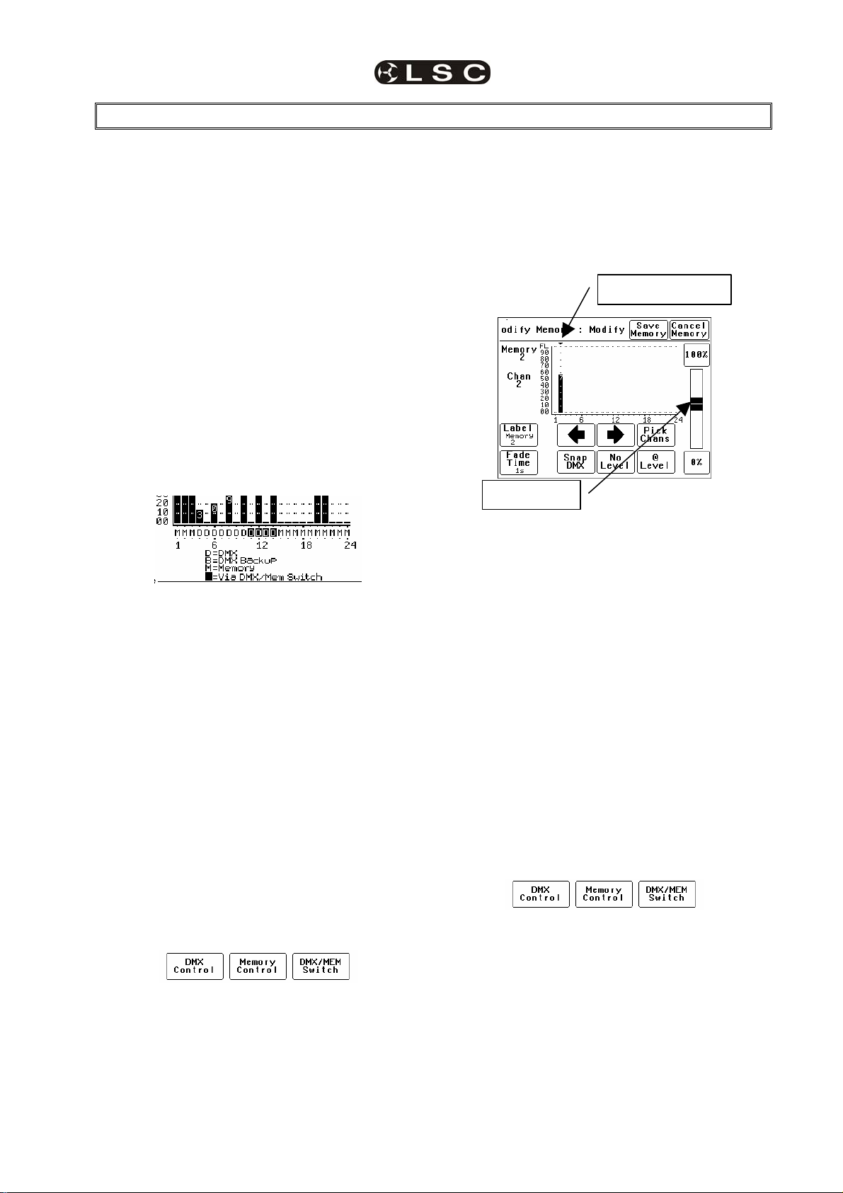
The row of characters below the level bar graph
on the main EKO screen shows the current
control source for each dimmer channel as
described by the legend on the screen.
In this example, channels 4 to 14 are all controlled
by DMX but 11 to 14 are via the DMX/Mem Switch
and can therefore be switched to Memory. All
other channels are controlled by Memories
1.1.1 Memory Control
When a dimmer channel is set to “Memory”, it is
always controlled by the EKO memories created
via the LCD touch screen or by taking “snapshots”
of a DMX input signal or a combination of both.
The memories are saved in the EKO and are
recalled using the buttons or faders on ePlates.
To set a dimmer channel to “Memory”, press;
[Menu] [Dimmer Channels] [Setup].
The screen shows the “Control Source” for each
dimmer channel.
To change the “Control Source” of a dimmer
channel(s), highlight the required dimmer
channel(s) by touching them, then press;
[Control Source].
The three choices for dimmer channel control
source are;
Press:
[Memory Control] [Save Setup] [Done] [Done].
1.1.2 Create or Edit memories
To Create or edit a memory press;
[Menu] [Memories] [Record Memory] or [Edit
Memory]. Select a memory number then press
[Pick].
You can either create your own memory using the
controls on the screen or press [Snap DMX] to
take a copy of the current DMX input signal.
When a channel(s) is selected (indicated by a
small triangle (b) above the channel) it can be
faded up or down by sliding your finger over the
virtual fader or instantly set to off or full using the
[0%] or [100%] buttons.
Selected Channel
Virtual fader
When the channel levels of the memory are
correct, press; [Save Memory] [Done].
To recall a memory, use a ePlate button or fader
that has been programmed to control that
memory.
1.1.3 DMX Control
When a dimmer channel is set to “DMX Control” it
is always controlled by the DMX signal from a
lighting console or other DMX device and it
responds to the DMX slot number to which it has
been patched in the EKO patch menu.
To set a dimmer channel to “DMX control”, on the
LCD touch screen press;
[Menu] [Dimmer Channels] [Setup].
The screen shows the “Control Source” for each
dimmer channel. To change the “Control Source”
of a dimmer channel(s), highlight the required
dimmer channel(s) by touching them, then press;
[Control Source].
The three choices for dimmer channel control
source are;
Press [DMX Control].
Press; [Save Setup] [Done] [Done].
1.1.3.1 DMX PATCHING
To Patch an EKO dimmer channel to a DMX slot
press; [Menu] [DMX Input] [Patch]
The “1 to 1 patch” provides a rapid method of
patching all of the dimmers in one EKO frame to
sequential DMX slots, starting from a DMX slot
that you select.
LSC Lighting Systems (Aust) Pty. Ltd Page 1
Page 6
EKO Quick Reference EKO Dimmer System
Operator Manual V2.3
Press [1:1 Patch] then type in the DMX start slot
number (0 to 512) for dimmer channel 1 in this
EKO frame, then press;
[Patch Series] [Save Patch] [Done] [Done].
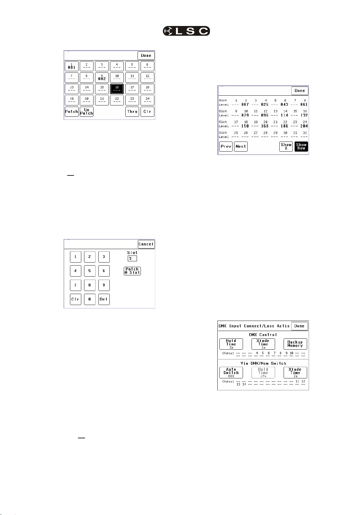
The “User Patch” allows you to individually patch
each EKO dimmer channel to a DMX slot of your
choice. Press [User Patch]. To select a channel,
press that channel number then press [Patch].
Type in the DMX slot number (0 to 512) for the
selected channel then press [Patch @ Slot].
touch screen or from a suitably programmed
ePlate.
To set a dimmer channel to “SWITCH” control,
press; [Menu] [Dimmer Channels] [Setup].
The screen shows the “Control Source” for each
dimmer channel.
To change the “Control Source” of a dimmer
channel(s), highlight the required dimmer
channel(s) by touching them, then press;
[Control Source]. The three choices for dimmer
channel control source are;
When all patches have been made, press;
[Done] [Save Patch] [Done] [Done].
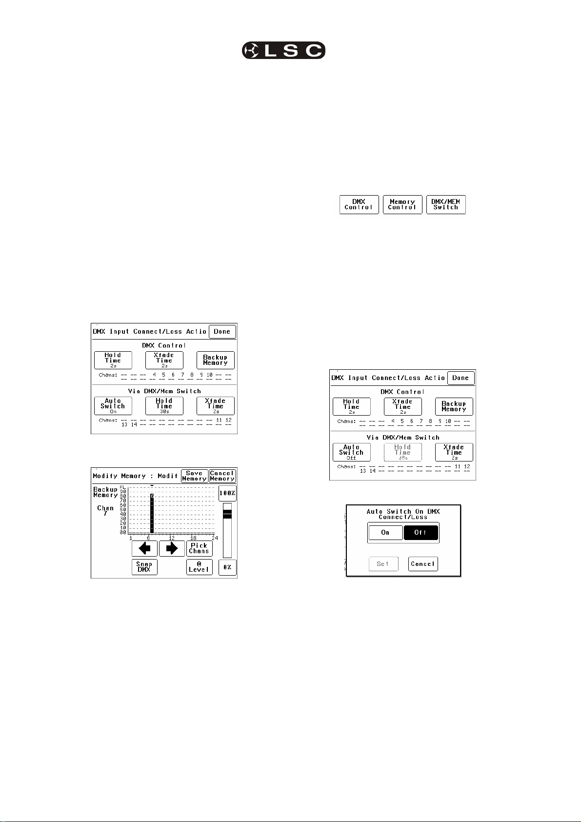
1.1.3.2 DMX BACKUP MEMORY
To create or edit the DMX “Backup Memory”,
press; [Menu] [DMX Input] [Connect Loss
Action].
Set the [Hold Time] to any time other than
“Infinite” then press [Set].
To replace the current EKO output with the
Backup Memory press; [Backup Memory].
Press [DMX/MEM Switch].
Press; [Save Setup] [Done] [Done].
To operate the switch use either a suitably
programmed ePlate button or from the LCD touch
screen press: [Menu], [Net Setup] [DMX/MEM
Switch]. Select either; [DMX] or [Memory] then
press [Set].
1.1.5 AUTO Switch
To configure the “Switch” (above) to
automatically switch to DMX whenever a valid
DMX signal is connected to the EKO press;
[Menu] [DMX Input] [Connect Loss Action].
The Backup memory screen appears;
You can either create your own memory using the
controls on the screen or press [Snap DMX] to
take a copy of the current DMX input signal.
When a channel(s) is selected (indicated by a
small triangle (b) above the channel) it can be
faded up or down by sliding your finger over the
virtual fader or instantly set to off or full using the
[0%] or [100%] buttons.
When the channel levels are correct, press;
[Save Memory].
Normal output is restored.
1.1.4 SWITCH Control
All channels set to “DMX/MEM SWITCH” can be
switched between Memory or DMX control. The
“switch” can be operated from either the LCD
Page 2
Press; [Auto Switch]
Press; [On] [Set] [Done] [Done] [Done].
1.1.6 TOUCH SCREEN Control
EKO dimmer channels can also be controlled from
the EKO’s front panel LCD touch screen. This
method of control is primarily used for testing
dimmer circuits.
To test a dimmer channel(s) press;
[Menu] [Dimmer Channels] [Chan Test]. Select a
channel(s) then fade the channel(s) up or down
with the virtual fader on the LCD screen or
instantly set them to off or full using the [0%] or
[100%] buttons
Channel test only allows one level to be set for all
selected channels. To set individual channels
levels use the “DMX Backup Memory” above.
LSC Lighting Systems (Aust) Pty. Ltd
Page 7
EKO Dimmer
Operator Manual V2.3
2 PRODUCT DESCRIPTION
2.1 ABOUT THIS MANUAL
This manual describes the installation,
configuration and operation of the EKO range of
slimline wall mount installation digital dimmers
and associated “ePlate” wall controllers
manufactured by LSC Lighting Systems.
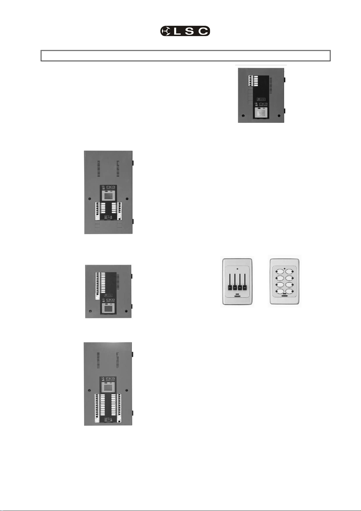
2.2 EKO MODELS
The EKO dimmer is available in 4 models
offering a choice of dimmer channel quantities
and power output ratings.
EKO 612/R
12 x 25 Amp Dimmer Channels
(shown with optional RCD Input Breakers)
EKO 606
6 x 25 Amp Dimmer Channels
All models can be controlled remotely via DMX
512 from a lighting console or from LSC
ePlates connected via LSCnet or locally from
their front panel LCD Touch Screen
2.3 EPLATES
ePlates ™ – Remote wall station controllers for
the EKO, allow users to recall internal memories
from the EKO for replay at a pre-programmed
level and with a selected fade time.
Note: The EKO dimmer must be fitted with
the LSCnet option to enable operation of
ePlates.
ePlates are available in the following
configurations;
EKO 312/R
12 x 13 Amp Dimmer Channels
(shown with optional RCD Input Breaker)
EKO 324/R
24 x 13 Amp Dimmer Channels
(shown with optional RCD Input Breakers)
4 Faders 8 Buttons
2 Faders 4 Buttons
1 Fader 2 Buttons
ePlates are connected to the EKO Dimmers via
LSCnet which uses industry standard Cat5
cables and connectors. The ePlate buttons and
faders can be programmed to recall lighting
memories stored in the dimmers or to operate
various EKO functions.
For example, a button might recall an EKO
memory. Another button might switch certain
dimmer channels between DMX control and
Memory (ePlate) control.
2.4 EKO CONTROL PHILOSOPHY
The EKO is an “ARCHI-TAINMENT” dimmer
with architectural control of EKO memories by
ePlates connected via LSCnet and
entertainment control by your lighting controller
connected via DMX-512A.
LSC Lighting Systems (Aust) Pty. Ltd Page 3
Page 8
Product Description EKO Dimmer
Operator Manual V2.3
The control source attribute for each EKO
dimmer channel can be individually configured
to control the channel from either:
2.5 MEMORY CONTROL
When configured for “memory” a dimmer
channel is controlled from ePlates (wall
controllers) that are used to recall memories
stored in the EKO dimmer.
See section 7.2.1.1 Control Source.
2.6 DMX CONTROL
When configured for “DMX” a dimmer channel is
controlled from a DMX lighting controller. If DMX
fails, the DMX levels can be held indefinitely or
the channels can fade to a “Backup Memory”
previously stored in the EKO.
See section 7.2.1.1 Control Source and section
When configured to “Switch”, a dimmer channel
can be switched between Memory or DMX.
Operation of the Switch is controlled from either
a suitably programmed ePlate button or from the
EKO touch screen or if Auto Switch is set to
ON it will be automatically switched to DMX
whenever a valid DMX signal is connected to the
EKO.
See section 7.2.1.1 Control Source.
Dimmer channels can be manually controlled
from the EKO front panel touch screen for
testing purposes.
See section 7.2.2 Channel Test.
2.7 SWITCHED CONTROL
2.8 LOCAL CONTROL
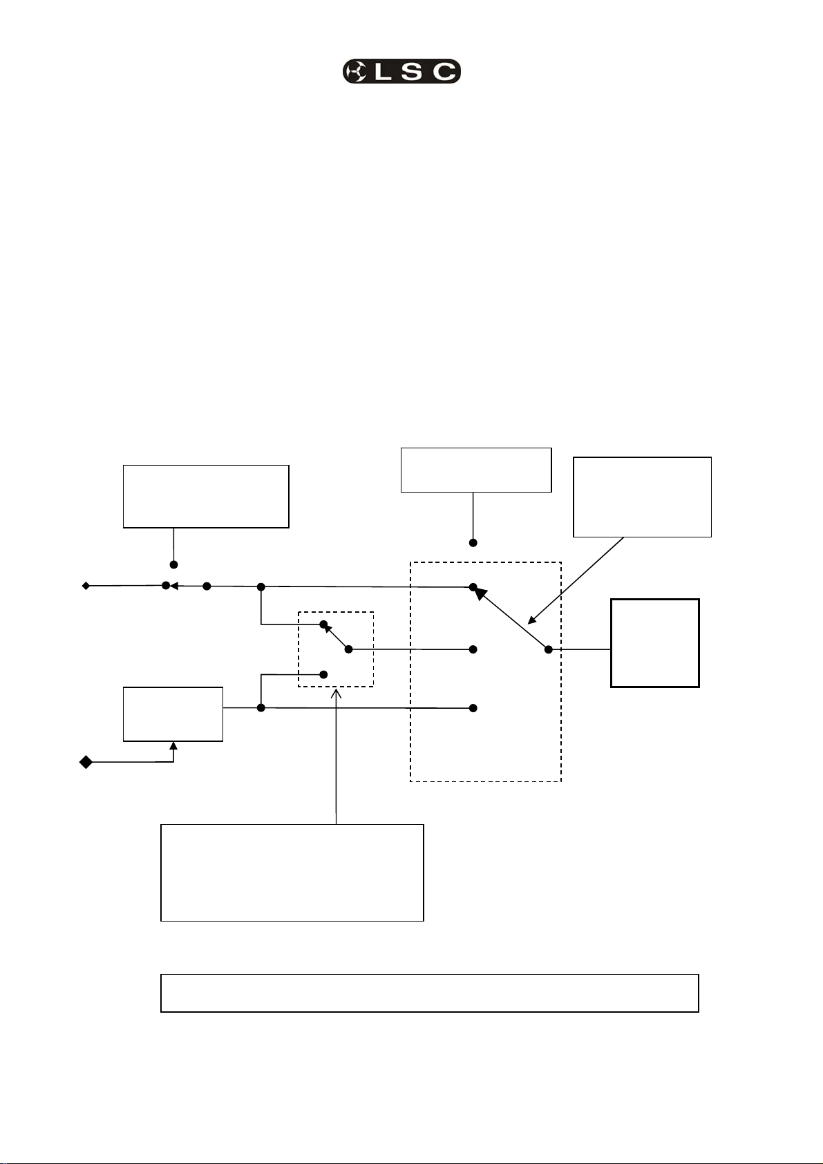
7.3.1 Patching.
“Back-up Memory”.
Can be automatically
recalled if DMX is lost.
Memories
1 to 80
LSCnet input
from ePlates recalls
memories
MEM/DMX Switch operated by either;
1. LCD Touch Screen
2. ePlate button
3. DMX input detected
MEM/DMX
Switch
(if Auto Switch is ON)
[Channel Test] via
LCD Touch Screen
DMX DMX Input
Switch
Memory
Dimmer Channel
Control Source
Individual
selection for
every dimmer
Channel.
Dimmer
Channel
EKO Dimmer Channel Control Options
Page 4
LSC Lighting Systems (Aust) Pty. Ltd
Page 9

EKO Dimmer Product Description
Operator Manual V2.3
2.9 OPTIONS
The following options are available;
2.9.1 LSCnet
LSCnet is a control and monitoring network
connecting the EKO to other devices such as
ePlates (wall controllers) and PCs running LSC’s
“Houston” monitoring software (see below).
LSCnet uses industry standard Cat5 cable and
RJ45 connectors for the interconnection of
devices. The EKO LSCnet option also supplies
the power for up to 4 ePlates via the Cat5 cable.
2.9.2 RCD Input Breaker
The EKO dimmers can be supplied with optional
factory fitted three phase input RCD (Residual
Current Device) protection. EKO models fitted
with RCD’s are identified by “/R” in the model
number.
The EKO324/R and EKO612/R are fitted with
two 63A 30mA RCD’s.
The EKO3312/R and EKO606/R are fitted with
one 63A 30mA RCD.
2.9.3 Single Phase Input
The EKO dimmers can be supplied to operate
from a single phase power input.
2.9.4 Switched Output Channels
The EKO can be supplied with outputs that only
switch between OFF and ON. These outputs
are suitable for controlling non resistive loads.
2.9.5 RCD Output Breakers
The EKO dimmers can be supplied with optional
factory fitted RCD output breakers. RCD
breakers are larger than normal MCB’s and
hence the maximum number of dimmer
channels is reduced.
2.9.6 “Houston” Monitoring Software
Houston is an optional Windows PC application
that allows the remote monitoring of all LSCnet
enabled products. This includes the EKO
dimmers and ePlate wall controllers.
Any operational faults such as input phase
failure, loss of DMX, over temperature are all
sent over the LSCnet from all of the devices to
one or more PCs running the Houston software.
The user is immediately notified of a fault when
the normally GREEN status indicator starts
flashing RED. A quick glance at the screen then
gives all the detailed information about the
device affected and the nature of the fault.
This information is invaluable for the fast
diagnosis of any problems in all situations. Large
stadium concerts or installations with dimmers in
different locations such as distant plant rooms
are now easily monitored from a central location.
Installers can see the status of a remote venue
such as a school, church or theme park from
their office via a Wi-Fi link or an internet
connection.
Houston also keeps a permanent log of all
system events for later viewing. These are
stored with the time and date of the fault,
allowing further diagnosis of a problem, even if it
is not reported until weeks later.
2.10 FEATURES
2.10.1 Installation Frame.
The EKO dimmers incorporate a cleverly
designed installation frame that can be fixed in
position without the dimmer being present.
Screw terminals on the installation frame allow
the load and control wiring to be terminated on
the frame in a clear and unhindered manner.
This allows the majority of the installation work
to be performed without the dimmer present.
The dimmer is therefore not subjected to
possible building site dust, water or damage.
When the installation is ready for
commissioning, the dimmer can be hung on the
installation frame and the dimmers and control
are then plugged into the special terminals on
the installation frame. To complete the
installation, the supply is connected to the
dimmers and the dimmers are configured. This
method allows the largest 24 channel dimmer to
be easily installed onto the frame and made fully
operational in less than 5 minutes.
2.10.2 LCD Touch Screen.
Dimmer configuration, patching and local control
is achieved via a backlit touch screen graphical
LCD on the front panel. A lock code can be used
to prevent unauthorised tampering.
2.10.3 Reversible Door.
The lockable hinged front door allows easy
access for servicing. The door has been
designed with reversible hinges and lock that
allows it to be customised to suit the installation
environment.
2.10.4 Low Noise Operation.
The dimmers are designed for 100% duty cycle
operation across all channels simultaneously.
The EKO features variable speed fan cooling to
minimise noise. The fan only operates when
required.
High quality toroidal inductors limit the rise time
to 300 micro seconds to minimise electrical
interference.
2.10.5 Variety of Output Loads.
Using LSC’s Pulse Transformer Fired Dimmer
(PTFD™) output circuitry means that virtually
any load can be controlled perfectly. Pin spots,
ELV lamps, transformers, strobes and even a
5w pilot lamp can all be smoothly controlled
without the need for dummy loads.
2.10.6 Fully Approved.
The EKO dimmers are CE and C tick approved.
LSC Lighting Systems (Aust) Pty. Ltd Page 5
Page 10
EKO Dimmer
Operator Manual V2.3
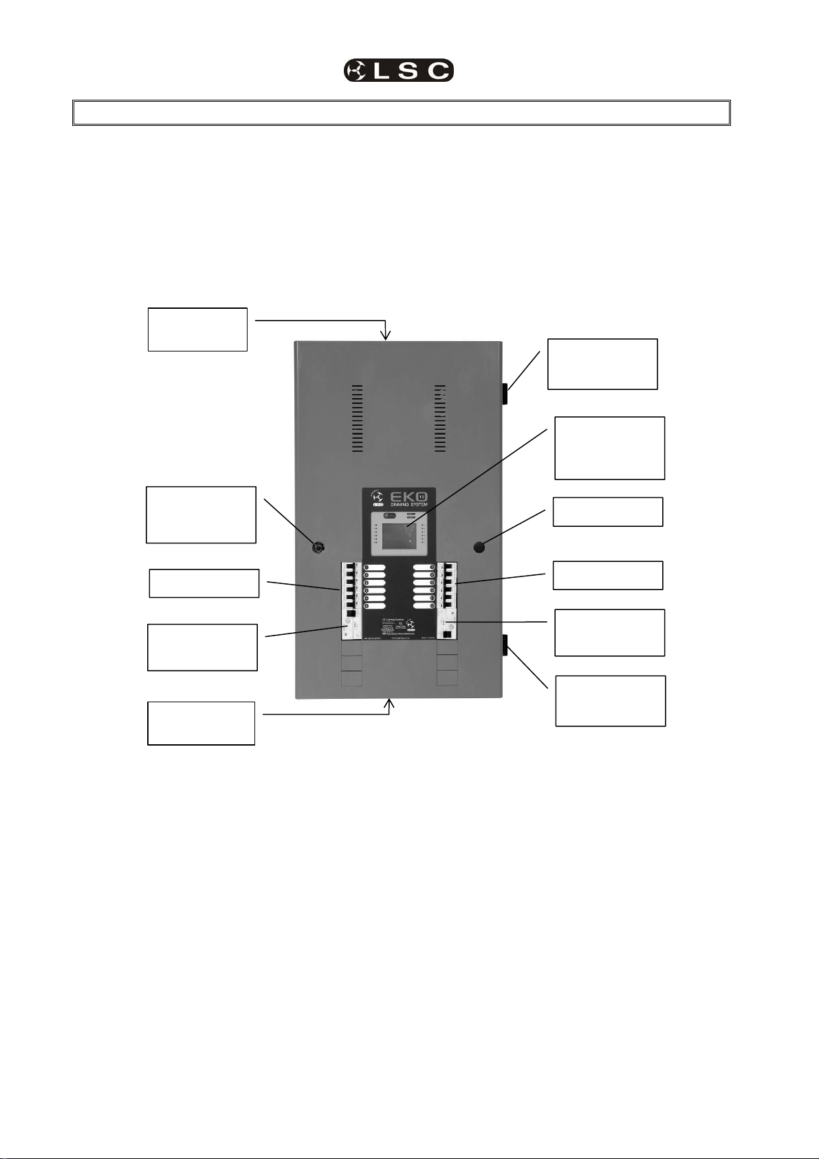
3 EKO Quick Tour
3.1 INTRODUCTION
All EKO models are constructed using two basic
cabinet sizes. Both cabinets have the same
width and depth, varying only in height.
• The tall cabinet is used for the EKO 612
and EKO 324.
• The short cabinet is used for the
EKO312 and EKO606
Cable Entry
Tunnel
Reversible
Front Panel
Lock
The front panel contains the input RCD circuit
breaker(s) (optional), load circuit breakers and
control panel that includes the status indicators
and LCD touch screen. The lockable front panel
provides internal access for installation and
maintenance. The front panel lock and hinges
can be reversed to swing the door in the
opposite direction.
No user serviceable parts are located inside.
Reversible
Hinge
LCD Touch
Screen
Control Panel
Blanking Plate
Output MCB’s
Input RCD
(Optional)
Cable Entry
Tunnel
EKO 612/R
3.1.1 Input RCD (Optional)
The optional three phase input RCD (Residual
Current Device) will cut the power to the EKO
dimmer if the residual current to earth at the input
exceeds 30 milliamps. It does not protect against
current overload. The input to the EKO must
always be connected to a suitably ratted external
circuit breaker even if the optional RCD is fitted.
See the specifications at the end of this manual
for the input ratings.
Page 6
Output MCB’s
Input RCD
(Optional)
Reversible
Hinge
3.1.2 Output (Load) MCB’s
The load connected to each dimmer channel
output is protected by a numbered MCB
(Miniature Circuit Breaker). An area beside each
load MCB is provided to write the name of the
load.
LSC Lighting Systems (Aust) Pty. Ltd
Page 11
EKO Dimmer Quick Tour
Operator Manual V2.3
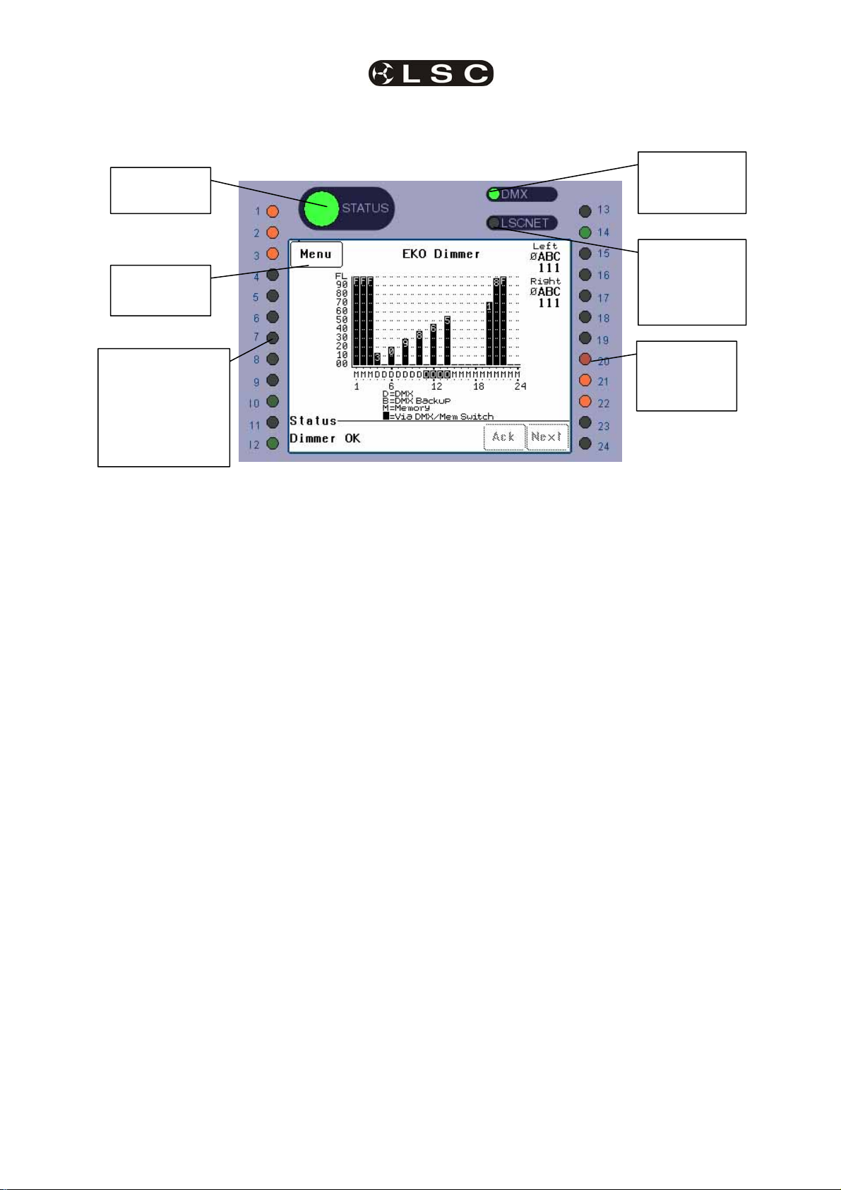
3.2 CONTROL PANEL
The Control Panel contains the indicators for status and channel levels and the LCD touch screen.
EKO Status
Indicator
LCD Touch
Screen
DMX Remote
Control Status
Indicator
LSC Net
(ePlate)
Remote
Control Status
Indicator
Channel level
indicators
1 to 12
Green = Controlled
by DMX
Red = Controlled
by Memory
Channel level
indicators
13 to 24
(if fitted)
Illustration shows an EKO 324 Control Panel. Control panels on other models vary only in the quantity of
channel level indicators.
3.2.1 Indicators
The indicators located around the touch screen
are multi coloured and light or flash to indicate
their current condition as described below;
EKO STATUS
• Green = Normal operation.
• Red (flashing) = Alarm. See status
message on LCD screen.
• Red (steady) = Alarm is acknowledged
but the problem still exists.
DMX
• Green = Valid DMX control signal
connected.
• Green (flashing) = Loss of DMX control
signal.
• Red (flashing) = Error on DMX control
signal.
LSCnet
• Green = Valid LSCnet control signal
connected (from ePlates).
• Green (flashing) = Data traffic detected
on LSCnet.
CHANNELS
• Green = The channel is ON via DMX
control.
• Red = The channel is ON via memory
(ePlate) or channel test control.
The brightness of the channel indicator is
proportional to the channel level.
See the, “Maintenance and Alarms” section for
further details on alarms.
LSC Lighting Systems (Aust) Pty. Ltd Page 7
Page 12

Quick Tour EKO Dimmer
Operator Manual V2.3
3.2.2 Touch Screen
The touch screen may be operated by touching
the virtual buttons with your finger. The home
page of the touch screen shows the current level
of each dimmer channel in a bar graph display.
If the EKO has been “locked”, the [Menu] button
is replaced by the [Unlock] button. Touching the
Dimmer Name
[Unlock] button and entering your code number
unlocks the EKO and reveals the [Menu] button.
Pressing [Menu] allows you to access a range of
functions, setups and tests via sub-menus. Each
sub-menu screen has help information in the top
left corner. The menus are fully described in
Section 7 “Menus”.
Menu button
Channel level
Scrolling Status
bar-graph
Messages
Status of Input
Power Phases A
B and C to Left
and Right (if fitted)
internal Modules.
1 = Present
0 = Not Present
Letter shows
current control
source for each
channel as per
legend on screen.
White text on black
shows control
source is via the
DMX/MEM Switch.
At the top of the screen is the name of this EKO
dimmer. The default name is “EKO Dimmer” but
you can enter a name of your choice from the
options menu. Names are useful in identifying
each EKO dimmer in installations containing
more than one EKO and can also be used by
the “Houston” monitoring software.
The middle of the screen is a bar-graph display
of the channel levels with channels numbers
shown across the bottom.
The levels from 00 to FL (Full) are shown on the
left scale in increments of ten, whilst the units of
each channel are shown on the individual
channel bars.
In the example above, channel 12 has a level of
46.
Channels can be individually configured to be
controlled from either “Memory” (ePlates),
“DMX” or “MEM/DMX Switch”. The letters below
the bargraphs show the control source for each
channel. The legend below the channel numbers
explains the meaning of the letters.
In the example above;
Channels 1 to 3 and channels 15 to 24 are
controlled by M (Memories recalled by ePlates).
Channels 4 to 10 are controlled by D (DMX).
Channels 11 to 14 (white letter on black
background) are also controlled by DMX but
control is via the MEM/DMX switch. Therefore
the switch is obviously in the DMX position. If
the switch was changed over to Memory, then
channels 11 to 14 would come under Memory
control.
If the switch has been set to “Auto Switch” to
DMX (if a DMX signal is present), then if the
DMX signal is lost, channels 11 to 14 would
automatically switch to Memory control.
See section 2.4 “EKO Control Philosophy” for
more details.
Depending upon the model of your EKO, it might
be fitted with one or two dimmer modules. The
EKO312 and EKO 606 only have a “Left”
module whilst the EKO324 and EKO612 have
both “Left” and “Right” modules.
The right hand side of the screen indicates the
presence of the 3 phases (Ø A B C) of input
power at the “Left” and “Right” dimmer modules
inside the EKO.
“1” below a phase letter indicates the
presence of that phase
“Ø” below a phase letter indicates a loss
of that phase.
The bottom of the screen displays scrolling
messages about the status of the EKO dimmer.
These are described in the “Maintenance and
Alarms” section.
Page 8
LSC Lighting Systems (Aust) Pty. Ltd
Page 13

EKO Dimmer
Operator Manual V2.3
4 EKO Dimmer Installation
4.1 INSTALLATION CONCEPT
Each EKO dimmer comprises of two parts;
• Installation Frame
• Dimmer Cabinet
The EKO installation is carried out in three
stages:
• Stage 1. The “Installation Frame” is
mounted on the wall and the load and
control circuits are connected to the
installation frame.
• Stage 2. The “Dimmer Cabinet” is hung
on the Installation Frame and plugged
into the load and control connectors on
the installation frame. The three phase
supply is then connected to the dimmer
cabinet.
• Stage 3. The EKO is configured for its
application.
This method allows the majority of the dimmer
installation work to be performed in stage 1,
without the dimmer cabinet present. All load
circuitry can be tested for correct connection on
the Installation Frame. The dimmer cabinet is
therefore not subjected to possible damage from
building site dust or debris or incorrect
connections.
4.2 SAFETY
All electrical work must be carried out by suitably
qualified persons.
The EKO dimmer is heavy. Ensure that the wall
mounting can support the weight. Use the
correct lifting procedures when handling the
EKO. Refer to the specifications below for the
weight of your EKO model.
The EKO dimmer system must be fed from a
suitable external three phase circuit breaker.
The optional RCD input breaker provides
Residual Current Protection only. It does not
protect the input circuit from current overloads.
Normal operation does not require the access
door to be opened. To avoid the risk of electric
shock, disconnect the supply before opening the
EKO for servicing. Refer any servicing to
qualified personnel.
4.3 UNPACKING
The EKO is fully tested and inspected before
leaving the factory. Upon delivery, inspect the
EKO for signs of damage or mishandling. In the
event of any damage, contact your LSC agent.
The EKO dimming system consists of two parts,
the EKO Installation Frame and the EKO
dimmer. The Installation Frame can be removed
from the EKO dimmer and given to the electrical
contractor to connect all load and control data
wiring. Whilst awaiting final commissioning of
the system, store the EKO dimmer in its original
carton in a clean and dry environment.
4.4 STAGE 1. INSTALLATION FRAME
& CABLING
4.4.1 Mounting the Installation Frame
The
EKO is primarily designed for wall mounting
on a solid flat vertical surface.
Cable entry can be from above or below via the
cable entry tunnels or directly through the wall
cavity. If either the top or bottom cable entry
tunnels are not used they should be covered by
fitting the blanking plates to the Dimmer Cabinet.
Attach the Installation Frame with suitable
fixings using all 6 mounting points shown below.
Ensure that the fixings can accommodate the
weight of the EKO (see below).
The Installation Frame contains the terminals
for the load and control cables. The power
input cable terminals are located on the dimmer
cabinet and are only connected in stage 2 when
the dimmer cabinet is hung on the installation
frame.
The mounting points, cable entry tunnels and
load cable access are similar for all models,
however the “three phase input” and DMX / LSC
Net cable access holes vary as shown in the
following illustrations.
LSC Lighting Systems (Aust) Pty. Ltd Page 9
Page 14

EKO Dimmer Installation EKO Dimmer
Operator Manual V2.3
The EKO312 Installation Frame is shown below. The Installation EKO606 Frame has the same
dimensions and cable access holes but is fitted with different load terminals.
Cable entry tunnel
Mounting
Point
Mounting
Point
Load cable
access
Load
terminals
Mounting
Point
Input Power
cable access
Mounting
Point
DMX and
LSC NET
Mounting
Point
DMX and
LSC NET
control cable
access
Mounting
Point
Cable entry tunnel
Model EKO312 EKO606
Weight (kg) 27 21
The EKO324 Installation Frame is shown below. The EKO612 Installation Frame has the same
dimensions and cable access holes but is fitted with different load terminals.
Cable entry tunnel
Mounting
Point
Load cable
access
Mounting
Point
Load
terminals
DMX and
LSC NET
Mounting
Point
Mounting
Point
DMX and
Input Power
cable access
Mounting
Point
LSC NET
cable access
Mounting
Point
Cable entry tunnel
Model EKO612 EKO324
Weight (kg) 30 35
Page 10
LSC Lighting Systems (Aust) Pty. Ltd
Page 15
EKO Dimmer EKO Dimmer Installation
Operator Manual V2.3
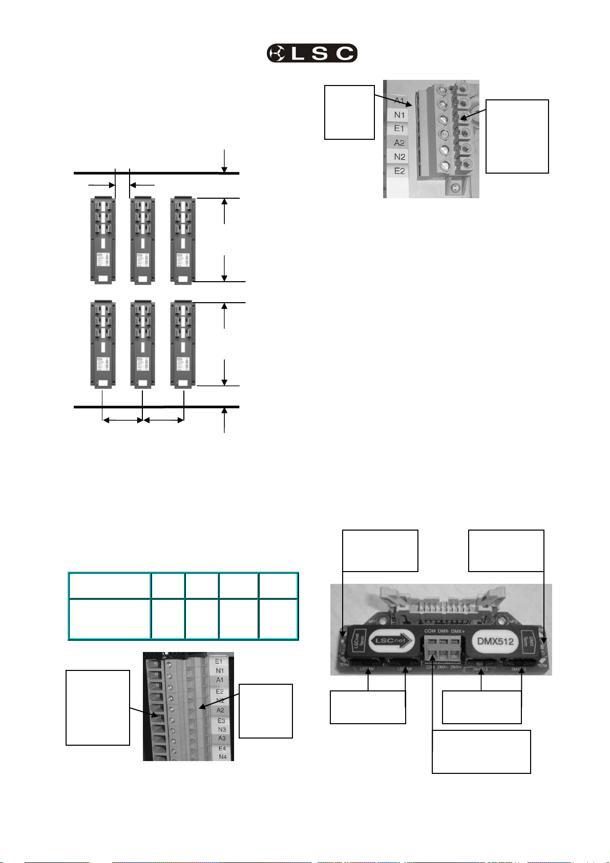
4.4.2 Installation Frame Spacing
When mounting the Installation Frames, observe
the minimum gaps between adjacent frames and
walls to allow sufficient ventilation.
340 mm
10mm²
Load
terminal
strip
In Stage 2,
dimmers
are
plugged
into these
sockets
150 mm
EKO 612 and 606 Load Terminals
4.4.4 Connecting Control Signals to
the Installation Frame
The EKO dimmer can be remotely controlled by
DMX512/1990-A or by LSC ePlates via the
LSCnet.
150 mm
150 mm
580 mm between centres
4.4.3 Connecting the Load Circuits to
the Installation Frame
Active (A), Neutral (N) and Earth (E)
connections are provided for each load circuit.
Connect the load circuits to the numbered “load
terminal strip” screw connections. The terminals
are suitable for stranded or single conductor
cables with the following sizes;
Model
EKO
324
EKO
312
EKO
612
EKO
606
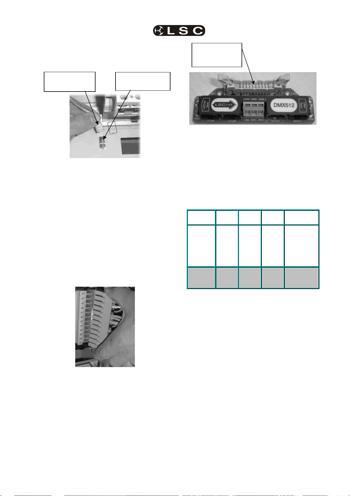
4.4.4.1 CONNECTING DMX512
DMX 512 is the industry standard for the
transmission of digital control signals between
lighting equipment.
DMX is usually “looped” from one piece of
equipment to the next. See “DMX Explained and
Typical Installations” for more information.
DMX 512 can be connected to the EKO by using
either the RJ45 connectors or the quick
connect terminals located on the connector
board on the Installation frame.
All DMX512 connectors are high impedance and
wired in parallel, allowing the DMX512 to be fed
into one connector and looped out of another.
The RJ45 DMX sockets can be used for either
DMX input or DMX output.
If using the quick connect terminals, connect
both the DMX input and output cables in parallel
into the same connectors.
LSCnet
Termination
switch
DMX512
Termination
switch
Load Terminal
Sizes
4mm² 4mm² 10mm² 10mm²
In Stage 2,
dimmers
are
plugged
into these
sockets
4mm²
Load
terminal
strip
LSCnet RJ45
connectors
EKO 324 and 312 Load Terminals
LSC Lighting Systems (Aust) Pty. Ltd Page 11
Installation Frame “Control Connector Board”
DMX512 RJ45
connectors
DMX512 Quick
connect terminals.
COM DMX- DMX+
Page 16
EKO Dimmer Installation EKO Dimmer
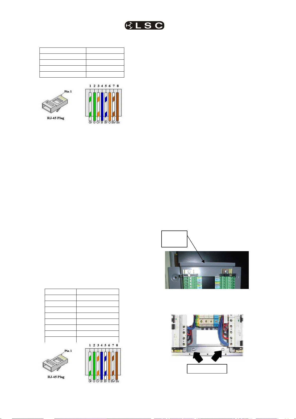
Operator Manual V2.3
DMX RJ45 Pin Numbers
RJ45 Pin Number DMX512
1 DMX +
2 DMX -
3,4,5 & 6 Not Used
7 & 8 DMX Common
Each device on the LSCnet has two RJ45
sockets allowing the LSCnet cable to be looped
from device to device. It is essential for correct
network operation that the first and last device
in the network be terminated and that all other
devices are not terminated. See section 5.4
LSCnet Cabling for more details.
If an EKO dimmer or ePlate has both of its
RJ45 sockets connected to the LSCnet then the
termination switch on that device must be set to
UNTERM.
If an EKO dimmer or ePlate has only one of its
RJ45 sockets connected to the LSCnet then the
The end of the DMX line must be terminated. A
DMX Terminator switch is located on the
Installation Frame “Control Connector Board”.
If the DMX line is looped out from an EKO
dimmer to another EKO or other DMX
equipment, then the termination switch must be
set to the UNTERM position.
If the DMX line is NOT looped out from an EKO
dimmer, then the termination switch must be set
to the TERM position.
4.4.4.2 CONNECTING LSCNET TO
THE INSTALLATION FRAME
The EKO dimmer can be remotely controlled
from LSC ePlates via the LSCnet.
Connection between devices on the LSCnet is
via RJ45 connectors using CAT5 cable. The
cable is run in a daisy chain that loops from
device to device. The cable carries both data
termination switch on that device must be set to
TERM.
The first stage of the installation process is
now complete.
4.5 STAGE 2.
INSTALLING THE EKO DIMMER CABINET
4.5.1 Hanging the Dimmer Cabinet on
the Installation Frame
When the load and control circuits have been
connected to the Installation Frame, the EKO
Dimmer cabinet can be hung on the Installation
Frame.
Remove the two ny-lock nuts from the bottom of
the Installation Frame and put them aside. Pick
up the Dimmer Cabinet and hang it on the
hanging lip at the top of the Installation Frame.
Hanging
Lip
and power. The maximum total length of the
cable is 800 metres. If longer cable runs are
required, a data repeater must be used to
regenerate the data. Contact your LSC agent for
details on data repeaters.
LSCnet RJ45 Pin Numbers
Pin Number LSCnet Function
1 Spare
2 Spare
3 LSC Net +
4 PSU +
5 PSU +
6 LSC Net 7 PSU 8 PSU -
Secure the Dimmer Cabinet to the bottom of the
Installation Frame using the two “ny-lock” nuts
that were previously removed.
Ny-lock Nuts
Page 12
LSC Lighting Systems (Aust) Pty. Ltd
Page 17
EKO Dimmer EKO Dimmer Installation
Operator Manual V2.3
4.5.2 Earthing the Dimmer Cabinet
Locate the earth wire spade connector on the
Dimmer Cabinet and connect it to the earth lug
on the Installation Frame.
Dimmer Cabinet
Earth wire
Installation Frame
Earth Lug
Socket for EKO
control panel
ribbon cable.
4.5.3 Hinging the EKO Door
The door of the EKO Dimmer can be hinged
from either side allowing easy access to the
inside of the dimmer in tight installation spaces.
To change the hinging, remove the door from
the EKO then move the hinges to the other side
of the door. Move the lock to the other side of
the door by swapping it with the blanking plug.
Refit the door. Ensure that the doors earth wire
is connected to the terminal on the EKO dimmer.
4.5.4 Plugging the Dimmers into the
Installation Frame
The output circuits of the EKO Dimmers are
terminated in the factory with special plugs that
fit directly into the load terminal strips of the
Installation Frame.
Installation Frame Connector Board
4.5.6 Connecting the Supply to the
Dimmers
Disconnect the power supply at the source
before terminating the supply cable in the EKO.
Depending upon the model of EKO, the three
phase supply is connected to either the input
screw terminals on the Dimmer Cabinet or
directly onto the optional “Input RCD” breaker on
the Dimmer Cabinet.
Model
EKO
324
EKO
312
EKO
612
EKO
606
Three
phase
current
capacity
104
Amps
52
Amps
100
Amps
50
Amps
(per
phase)
Supply
Terminal
35mm² 16mm² 35mm² 16mm²
Sizes
Note: The EKO Dimmer and the supply cable
feeding it must always be protected by a suitable
circuit breaker. Even if the EKO Dimmer is fitted
with the optional input RCD (Residual Current
Device) circuit breaker(s) an external circuit
breaker must be used because the EKO RCD
breaker(s) do not protect against overload
currents.
4.5.7 Single Phase Input Option
Plug the dimmers into their matching load
sockets.
4.5.5 Plug the DMX Control into the
Installation Frame
Plug the ribbon cable connector attached to the
EKO “Control Panel” into the “Installation Frame
Connector Board”.
The EKO can be factory wired for a single phase
input.
Disconnect the power supply at the source
before terminating the supply cable to the input
screw terminals on the Dimmer Cabinet.
The EKO612 and EKO324 require TWO single
phase cables to be connected. This is because
a single cable capable of carrying the maximum
load current has a large bending radius that
cannot be accommodated by the EKO.
LSC Lighting Systems (Aust) Pty. Ltd Page 13
Page 18
EKO Dimmer
Operator Manual V2.3
5 ePlate & LSCnet Installation
ePlates are the remote wall station controllers
for the EKO dimmers or other LSCnet enabled
products. The ePlates allow you to recall
internal memories from the EKO for replay at a
pre-programmed level and fade time. ePlates
can also be programmed to perform other
functions such as selecting memory or DMX
operation or locking out other ePlates. ePlates
are connected to the EKO dimmers via a
communications bus called LSCnet.
5.1 SPECIFICATIONS
The initial ePlate wall stations are all based on
the Australian standard single gang electrical
switch plate.
The dimensions of the current ePlate are :
• 116mm High
• 76mm Wide
• 40mm Deep
To install the ePlate a hole is required in the
surface or wall where the ePlate is to be
mounted.
Cut Out Dimensions :
• 70mm High
• 50mm Wide
• 25mm Deep
In the future LSC will be offering units to suit
most countries standard switch plates.
5.2 MODELS
ePlates are available with either buttons or
faders.
• Turn off all memories.
• Switch specific channels between Memory or
DMX control.
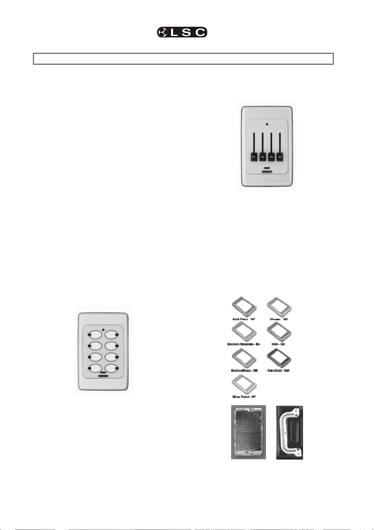
5.2.2 eFader
Available with 1, 2 or 4 faders.
Each fader can be programmed for any of the
following functions:
• Control the level of an individual memory.
• Control the level of multiple memories.
• Act as a MASTER level control over a group
of channels (zone).
• Manual control of a single channel.
• Live fade time control.
5.2.3 Installation Accessories
A range of decorative surrounds are available to
suit the ePlates.
5.2.1 eButton
Available with 2, 4 or 8 buttons.
Each button can be programmed to control up to
4 independent events, allowing complex
functions to be easily operated by a novice.
Each button has an associated indicator that is
independently programmable.
Buttons can be programmed for any of the
following functions:
• Fade an individual memory to a specific level
in a specific fade time.
• Fade multiple memories to a specific level in
a specific fade time.
• Lock or Unlock other ePlates.
Masonry mount metal wall box (fire rated) and
Plasterboard Clip mount
Page 14
LSC Lighting Systems (Aust) Pty. Ltd
Page 19

EKO Dimmer ePlate and LSCnet Installation
Operator Manual V2.3
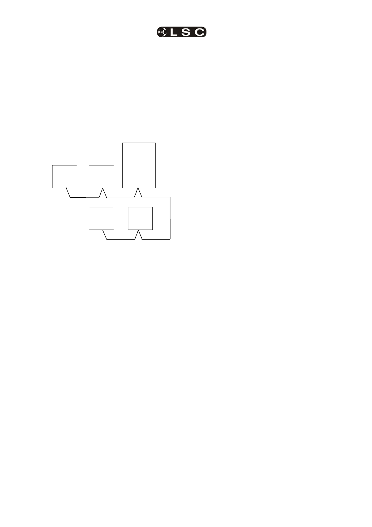
5.3 LSC NET CABLING
LSCnet uses Cat5 cable for the interconnection
of devices and all devices are connected in a
daisy chain fashion. All connections are via
industry standard RJ45 connectors.
EKO
Dimmer
ePlate
ePlate
ePlate
• If the LSCnet cable run ends (terminates) at
a device then the termination switch on that
device must be set to TERM.
• If the LSCnet cable run loops through a
device then the termination switch on that
device must be set to UNTERM.
Each ePlate has a main processor board with a
small “LSC Net Connection Board” plugged into
the back of it. This “LSC Net Connection Board”
contains the two network RJ45 connectors and
the “LSCnet TERMINATE SWITCH”.
Cat5 cable daisy chained between devices.
The LSCnet cable is used to carry both data and
power for the ePlates. LSCnet uses a modified
version of CAN bus, which guarantees that
EVERY command message arrives at it’s
destination, no matter how busy the network
becomes. Architectural systems based on RS485 cannot offer this promise, messages can
(and do) get lost, causing the system to miss
important buttons presses.
Each LSCnet enabled product (EKO dimmer,
ePlates, e24 dimmer, TEKO dimmer) is known
as a “device”. Each device has two LSCnet
connectors allowing the Cat5 cable to be looped
from device to device. The EKO can be located
anywhere in the LSCnet network.
The normal rules for data cabling apply.
• You must allow a minimum of 30cm
separation from mains power (or more if
required by local regulations).
• If you must cross over a mains power cable,
always do this at 90 degrees to the power
cable.
• LSCnet cabling must always be a daisy
chain. No Y-splits or T junctions are allowed.
5.4 LSCNET TERMINATION
The LSCnet must be correctly terminated.
Termination is required at BOTH ends of the
data cabling.
EKO
Dimmer
ePlate
ePlate
ePlate
LSCnet
Terminate
Switch
If an ePlate needs to be removed for service or
testing, the LSC Net Connection Board can be
left in circuit, thus maintaining the network
integrity.
5.5 LSCNET LIMITS
There are limits to the number of devices that
can be powered by the system and limits to the
total length of cable in the network. However,
these limits can be extended by adding power
supply boosters and data repeaters.
The power for the ePlates is supplied from the
EKO dimmer via the Cat5 cable.
EKO
Dimmer
Rear view of ePlate
5.5.1 Power Limits
ePlate
LSC Net
Connection
Board
ePlate
TerminateTerminate
ePlate
ePlate
A single EKO can power up to 4 ePlates
LSC Lighting Systems (Aust) Pty. Ltd Page 15
Page 20
ePlate and LSCnet Installation EKO Dimmer
Operator Manual V2.3
Each additional EKO dimmer allows an
additional 4 ePlates to be powered (i.e. the
power supplies add together).
• 2 EKO Dimmers can power up to 8 ePlates.
• 3 EKO Dimmers can power up to 12 ePlates
If your installation exceeds the limits you will
need to add a “power booster”. Contact your
LSC agent for details.
5.5.2 Cable Limits
Up to 800 meters of Cat5 can be installed
before a data repeater is needed.
EKO
Dimmer
ePlate
ePlate
ePlates in their remote locations, connect them
to the EKO via short Cat5 cables so you can
observe all devices on the network correctly
operating.
When all of the devices are working correctly,
disconnect the short Cat5 cables then gradually
build up the network by connecting the actual
network cabling, one ePlate at a time.
Connect the first ePlate and switch its
“terminate” switch to TERM. Check the ePlate
operation then switch its “terminate” switch to
UNTERM and connect the Cat5 cable that loops
onto the next (terminated) ePlate.
When that ePlate operates correctly, unterminate it then connect and test the next
ePlate.
When you are satisfied that the system works
correctly, screw in the ePlates.
ePlate
150m 250m
350m
ePlate
50m
Maximum total of 800 metres of Cat5 cable.
If an installation requires more than 800m of
cabling then an LSCnet data repeater is
required. Contact your LSC agent for details.
5.5.3 Device Limits
In an EKO installation, every EKO dimmer and
every ePlate is known as a device.
A maximum of 32 devices can be connected to a
network before a data repeater is required.
Up to 65,535 devices can exist on an LSCnet
installation.
5.6 PROGRAMMING EPLATES
The functions of the buttons and faders on
ePlates can be programmed by a separate
computer program however ePlates are shipped
from the factory with pre-programmed standard
configurations that suit most requirements
See section 8; Memory (ePlate) Control, for
details on pre programmed ePlates and how to
customise the buttons and faders for special
requirements.
5.8 REMOVING EPLATES
Each ePlate has a main processor board with a
small “LSC Net Connection Board” plugged into
the back of it. This “LSC Net Connection Board”
contains the two network RJ45 connectors and
the network termination switch.
If an ePlate needs to be removed for service or
testing, the LSC Net Connection Board can be
left in circuit, thus maintaining the network
integrity.
This feature also allows you to run all the
network cabling and join the cables using the
LSC Net Connection Boards without installing all
of the actual ePlates.
5.7 COMMISIONING LSCNET
The best approach to commission a network is
to activate it a small part at a time, and then
build on the working system. This ensures that
each device is working correctly before the next
device is added.
Start at the EKO dimmers, as they contain the
LSC Net Power Supply. Before installing the
Page 16
LSC Lighting Systems (Aust) Pty. Ltd
Page 21

EKO Dimmer
Operator Manual V2.3
6 Testing and Configuring the EKO Dimmer
When an EKO dimmer is installed, it needs to be
configured to suit its particular installation and
application.
This involves the following operations which are
achieved via the touch screen menus. The menu
system is fully described in section 7.
6.1 TESTING
Testing the operation of each dimmer circuit.
See section 7.2.2 Channel Test.
6.2 DIMMER CONTROL SOURCE
Each dimmer channel needs to configured for
the “Control Source” that will control it. This
could be either; DMX, Memory or SWITCH
(switch-able between Memory or DMX).
See section 7.2.1.1 Control Source.
The SWITCH (above) can be manually operated
either locally from the LCD touch screen or
remotely from an ePlate.
See section 7.5.1 DMX/MEM Switch Operation
and section 7.5.2 Switch Group.
The SWITCH can be automatically operated by
the presence or absence of DMX.
See section 7.3.6.2 DMX/MEM Switch Connect
Loss Action.
Note: If “Control Source” is not available on
the menu then either “Net Playback” has
been disabled from the “Options” menu or
your EKO is not fitted with the “LSCnet”
circuitry. Contact your LSC agent for details
on how to upgrade your EKO to include
LSCnet.
6.3 PATCHING
Dimmer channels set to DMX or Switch Mode,
may need to be patched to the DMX slot number
that is to control them.
See section 7.3.1 Patching.
6.4 RECORDING MEMORIES
Dimmer channels set to Memory Mode, are
controlled by the memories (up to 80 memories)
saved in each EKO. These memories must be
created and saved in the EKO. You can also
create memories by taking a snapshot of the
DMX input.
See section 6.4 Recording Memories.
The ePlates (wall plates) must also be
programmed to recall the required memories.
See section 8 Memory (ePlate) Control.
6.5 OPTIONAL SETTINGS
In addition to these settings you can also set the
following optional parameters;
• Selecting the dimmer reaction of DMX
controlled channels when the DMX
signal is connected or lost including the
saving of a Backup Memory.
See section 7.3.6 Connect Loss Action
• Selecting minimum and maximum levels
for each dimmer.
See section 7.2.1.2 Min and Max
Levels
• Selecting a fade curve for each dimmer.
See section 7.2.1.3 Fade Curve
• Setting each dimmer to either Dim
(dimmer) or Switch (between OFF or
fully ON).
See section 7.2.1.3 Fade Curve
• Setting a “lock code” to prevent
unauthorised access to the EKO menu
system.
See section 7.6.4 EKO Lock / Unlock
• Naming the Dimmer. Useful in large
installations to identify each EKO.
See section 7.6.6 Name
• Setting the date and time (for the EKO
status log).
See section 7.6.7 Time and Date
• If the EKO is not connected to ePlates
and is ONLY to be controlled by DMX
then the Memory control by ePlates via
LSC net can be disabled. This simplifies
the menu system and forces all dimmer
channels to DMX control.
See section 7.6.8 Net Playback
• The DMX alarm delay time can be set or
the alarm can be disabled. Disabling the
alarm is useful when the EKO is only
controlled by ePlates.
See section 7.3.7 DMX Alarm.
LSC Lighting Systems (Aust) Pty. Ltd Page 17
Page 22

EKO Dimmer
Operator Manual V2.3
7 MENU SYSTEM
7.1 TOUCH SCREEN MENUS
When the EKO is switched ON, after briefly
showing the opening screen, the top level
Pressing [Menu] reveals the “Main Menu”.
screen appears;
The six buttons on the “Main Menu” provide
access to the Sub-Menus and functions which
are described in detail on the following pages.
Each sub menu has a description of its function
at the top of its screen.
7.1.1 EKO Menu Structure
Each main menu button accesses the following sub menu functions;
Dimmer
Channels
Set-up Chan Test
Control Source.
(DMX, Memory or
Switch)
Min Level
Max Level
Fade Curve
Net Group Master.
Manual channel(s) level test
Channel test sequencer
Patch View Levels
1:1 Patch
User Patch
Clear Patch
Connect Loss Action DMX Alarm
DMX Control
Hold Time
Xfade Time
Backup Memory
Via DMX/MEM Switch
Auto Switch On/Off
Hold Time
Xfade Time
Memories
Record
Memory
Delete
Edit
Memory
Copy
Memory
Memory
MEM/DMX
Switch
Manually operate the
“MEM/DMX Switch”.
Options
Module Status Beeper About
Input Phases
A B C
Temperature
Fan Speed
Lock Dimmer
4 digit code to
lock
Date and
Time
Set Time
Set Date
On
or
Off
Change Lock
Code
Default = 0000
Net Playback
Enable or Disable
Memory playback
from ePlates
Software
Version
Model type
Voltage
Dimmer Name
Enter a name
Reset
System Reset
Total Reset
Displays Log
Page 18
DMX
Input
Raw levels
Percentage
Alarm Enable/Disable
Alarm Delay Time
Net
Setup
Switch Group
Set Switch Group
Number or None for
ePlate control of
MEM/DMX Switch.
Log
Clear Log
LSC Lighting Systems (Aust) Pty. Ltd
Page 23

EKO Dimmer Menus
Operator Manual V2.3
Select a menu by touching the appropriate
button on the touch screen.
To step back through the menus, press the
button in the top right of the screen.
The choices will be either;
[Done] (Exits to previous menu)
or, if changes have been made;
[Save] (Exits to previous menu and saves
changes)
or
[Cancel] (Exits to previous menu and restores
previous settings).
7.2 DIMMER CHANNELS MENU
Selecting [Menu] [Dimmer Channels] provides
menus for;
• Setup (of channel attributes)
• Channel Testing
7.2.1 Set-Up
Selecting [Menu] [Dimmer Channels] [Setup]
reveals the following screen;
The § and ¨ buttons at the bottom left of the
screen step through the attributes that can be
set for each individual dimmer channel.
The available attributes are;
• Control Source
• Min Level
• Max Level
• Fade Curve
• Net Master Group
As each attribute is selected, the screen shows
the setting of that attribute for every channel.
In the example above of a 24 channel EKO, the
“Control Source” attribute for every channel is
shown.
• Channels 1 to 3 and 15 to 24 are controlled
by EKO memories (recalled from ePlates).
Attribute
Button
In this example, channels 22, 23 and 24 are
selected.
To de-select a channel, touch that channel
again.
To de-select all
channels press [Clr].
To select a range of channels, press a channel,
then [Thru] then another channel.
When any channels are selected, the attribute
button becomes active. Pressing the attribute
button allows you to change the attribute of the
selected channel(s) as described below.
The default settings for channel attributes are;
ATTRIBUTE DEFAULT SETTING
Control Source Switch
Min Level 0%
Max Level 100%
Fade Curve S Law
Net Master Group None
Descriptions of each attribute and how to set
them are described below.
When the all attributes are correct for all
channels press [Save Setup], or to cancel the
changes that you have made and return to the
previous settings press [Cancel].
7.2.1.1 CONTROL SOURCE
The “Control Source” attribute selects the signal
that will control the level of a dimmer channel.
Press; [Menu] [Dimmer Channels] [Setup]. The
screen shows the control source for every
channel. To change the control source, select a
channel(s) (by touching them) then press
[Control Source]. You can select the following
sources;
• Channels 5 to 10 are controlled by DMX.
• Channels 11 to 14 can have their control
“switched” between either Memory or DMX.
To change the selected attribute of a channel(s),
select the channel(s) by touching them.
Selected channels have white text on a black
background.
1. DMX Control. When configured for “DMX
Control” a dimmer channel is only controlled
from the DMX signal from a lighting controller.
Note: If a dimmer channel is controlled by
DMX, it might need to be patched. See Error!
LSC Lighting Systems (Aust) Pty. Ltd Page 19
Page 24

Menus EKO Dimmer
Operator Manual V2.3
Reference source not found. “Patching” for
details.
2. Memory Control. When configured for
“Memory Control” a dimmer channel is
controlled from ePlates (wall plates) that are
used to recall memories stored in the EKO
dimmer. These memories can be created and
edited via the LCD touch screen.
3. DMX/MEM Switch. When configured to
“Switch”, a dimmer channel can be manually or
automatically switched between DMX or
Memory control.
Manual operation of the “DMX/MEM
Switch” is controlled either “remotely” from a
suitably programmed button on an ePlate or
“locally” from the EKO touch screen.
See section Error! Reference source not
found. “DMX/MEM Switch Operation” for details
on how to manually operate the “DMX/MEM
Switch” from the touch screen.
Automatic operation of the “Switch” is
controlled by the presence or absence of a valid
DMX signal from a DMX lighting controller.
When DMX is present it will be automatically
connected to any channels that are set to
“Switch”.
See 7.3.6.2 “DMX/MEM Switch Connect Loss
Action” for details on how to set the “DMX/MEM
Switch” to “Auto Switch” to DMX.
When finished press [Save Setup] [Done]
When finished press [Save Setup] [Done]
[Done].
7.2.1.3 FADE CURVE
Fade Curve is the curve or “transfer
characteristic” between input control signal and
dimmer output. The following curves are
available;
• S Law
• Square Law
• Cube Law
• Quad Law
• Non Dim
• Relay
• 120V (Volt)
• 80V (Volt)
Press; [Menu] [Dimmer Channels] [Setup] then
use the § and ¨ buttons to select “Fade Curve”.
When you select a channel(s) (by touching it)
then press [Fade Curve], you can select the
required curve for the selected channel(s).
[Done].
7.2.1.2 MIN AND MAX LEVEL
The “Min Level” attribute sets the level of the
dimmer output when the control signal is set to
minimum. Setting this value slightly above zero
is useful to “Pre-Heat” lamp filaments.
“Max Level” sets the level of the dimmer output
when its control signal is set to maximum.
Press; [Menu] [Dimmer Channels] [Setup] then
use the § and ¨ buttons to select “Min Level” or
“Max Level”.
When you select a channel(s) (by touching it)
then press [Min Level] or [Max Level], you can
use the keypad that appears to enter the
required percentage level for the selected
channels, then press [Set].
“S Law” is the default law and provides a normal
dimmer response.
“Square”, “Cube” and “Quad” laws can be
selected to better match the transfer
characteristic of existing dimmer installations or
to provide the response that you require. Try the
different curves to find the best curve for your
needs.
“Non Dim” is used for devices that do not fade,
but need to be switched OFF or ON such as
motors or discharge lamps.
When set to “Non Dim”, when the control signal
is raised above 60%, the dimmer will switch from
OFF to full ON and when the level drops below
40%, the dimmer will switch OFF.
Page 20
LSC Lighting Systems (Aust) Pty. Ltd
Page 25

EKO Dimmer Menus
Operator Manual V2.3
“Relay” ” is used for devices that need to be
switched OFF or ON. It is similar to “Non Dim”
but uses different thresholds for switching.
When set to “Relay”, if the level is raised above
4%, the dimmer will switch to full ON and when
the level drops below 2%, the dimmer will switch
OFF.
Relay mode is particularly useful when long fade
times are used as the “Relay” channel will switch
on at the start of the up fade and switch off at
the end of the down fade.
“120V” limits the maximum output voltage of the
selected channels to 120 Volts. Use this setting
for 120Volts lamps.
“80V” limits the maximum output voltage of the
selected channels to 80 Volts. Use this setting
When finished press [Save Setup] [Done]
[Done].
7.2.2 Channel Test
Pressing [Menu] [Dimmer Channels] [Chan
Test] provides local control of dimmer levels
from the touch screen for testing purposes.
for 80Volts lamps.
When finished press [Save Setup] [Done]
[Done].
7.2.1.4 NET MASTER GROUP
ePlate fader panels can be programmed so that
a fader acts as level “Group Master” over
specified dimmer channels that are under
memory control. Any dimmer channels that are
assigned to a “Group Master” will still be
controlled by the playback of memories, but the
ePlate Group Master will have master level
control.
For example, if a channel is played back from a
memory with a level of 50% and its Group
Master is set to 50% then the channels level will
be 25%.
[Net Master Group] allows you to assign each
dimmer channel to a group number so that the
channels overall level is controlled by an ePlate
“Group Master fader” with the same group
number.
Press; [Menu] [Dimmer Channels] [Setup] then
use the § and ¨ buttons to select “Net master
Group”. When you select a channel(s) (by
touching it) then press [Net Group Master], you
can select the group number of the ePlate group
fader that is to be a group master over that
channel(s) or for no group master press [None].
When you have made your selection press;
[Set].
The screen shows the current level of each
dimmer channel. This level might be coming
from the DMX control input or a memory recalled
from an ePlate.
To test a dimmer channel(s), press the dimmers
channel number(s). Selected channels have
white text on a black background. In the
example above, channel 1 is selected. You can
add further channels to your selection by
pressing their channel numbers.
To deselect a channel, press it again.
To select a range of channels, press a channel,
then [Thru] then another channel.
To clear all
selections, press [Clr].
When a channel(s) is selected it is disconnected
from either the DMX or Memory control signal
and connected to the virtual fader on the right of
the touch screen. It can be faded up or down by
sliding your finger on the virtual fader.
To instantly set the fader to 0% press the button
at the bottom of the fader.
To instantly set the fader to 100% press the
button at the top of the fader.
When a channel is deselected, it is disconnected
from the virtual fader and returns to its previous
DMX or memory control.
7.2.3 Test Sequencer
The Channel Test screen provides a simple
sequencer that will automatically step through
the channels. As each channel(s) is selected it is
disconnected from either the DMX or Memory
LSC Lighting Systems (Aust) Pty. Ltd Page 21
Page 26
Menus EKO Dimmer
Operator Manual V2.3
control signal and connected to the virtual fader
on the right of the touch screen
• Select a channel (or several channels).
• Set a level on the virtual fader.
• To start the sequencer, press
[X](forward).
• To stop the sequencer press [] (stop).
• To manually step the stopped sequence
to the next channel press []
• To play the sequence in the opposite
direction press [W] (reverse).
When finished testing channels press; [Done]
[Done] [Done].
All dimmers return to normal control.
Hint: When testing lamps locally from the
EKO control panel, the test sequencer is
especially useful if the lamps are in a
different location to the EKO dimmer. You
can start the sequencer then go and check
that each lamp is working as the EKO
automatically sequences through the dimmer
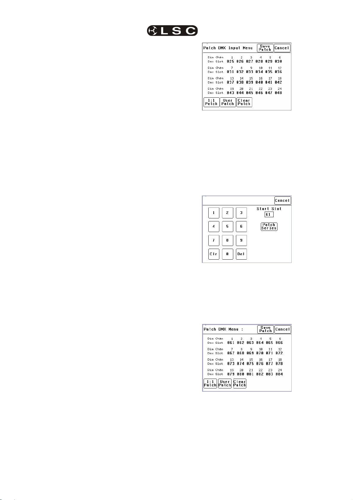
In this example, “Dim Chans” 1 to 24 are
patched to “DMX Slots” 025 to 048 respectively.
7.3.2 1 to 1 Patch
Patches are often performed in contiguous
blocks of addresses. The 1 to 1 patch provides a
rapid method of patching all of the dimmers in
one EKO frame to sequential DMX slots, starting
from a DMX slot that you can select.
Press [Menu] [DMX Input] [Patch] [1:1 Patch].
channels.
7.3 DMX INPUT MENU
Selecting [Menu] [DMX Input] provides menus
for;
• Patching.
• Viewing DMX Levels.
• Dimmer reaction to connection and loss
of DMX signal.
• DMX alarm settings.
7.3.1 Patching
The patch allows you to patch (connect) DMX
slots (addresses) from your DMX lighting
controller to EKO dimmer channel numbers.
Each EKO dimmer cabinet numbers its dimmer
channels from channel 1 through to channel 6 or
12 or 24, depending upon the quantity of dimmer
channels in the model of EKO.
Patches are required when;
• A particular DMX slot number from the
lighting controller is to control an EKO
dimmer with a different dimmer channel
number.
• A single DMX slot number is to control
multiple EKO dimmer channel numbers.
To patch EKO dimmers to DMX slots or to
examine the current patches, press;
[Menu] [DMX Input] [Patch].
Type in the DMX start slot number (0 to 512) for
dimmer channel 1 in this EKO frame then press
[Patch Series].
In this example, the starting DMX slot number is
61. Each EKO dimmer is automatically patched
to the next higher DMX slot number.
To save the patch, press [Save Patch] or, to
cancel the changes that you have made and
return to the previous patch, press [Cancel].
Page 22
7.3.3 User Patch
The User Patch allows you to individually patch
each EKO dimmer channel to a DMX slot of
your choice.
Press [Menu] [DMX Input] [Patch] [User
Patch].
LSC Lighting Systems (Aust) Pty. Ltd
Page 27
EKO Dimmer Menus
Operator Manual V2.3
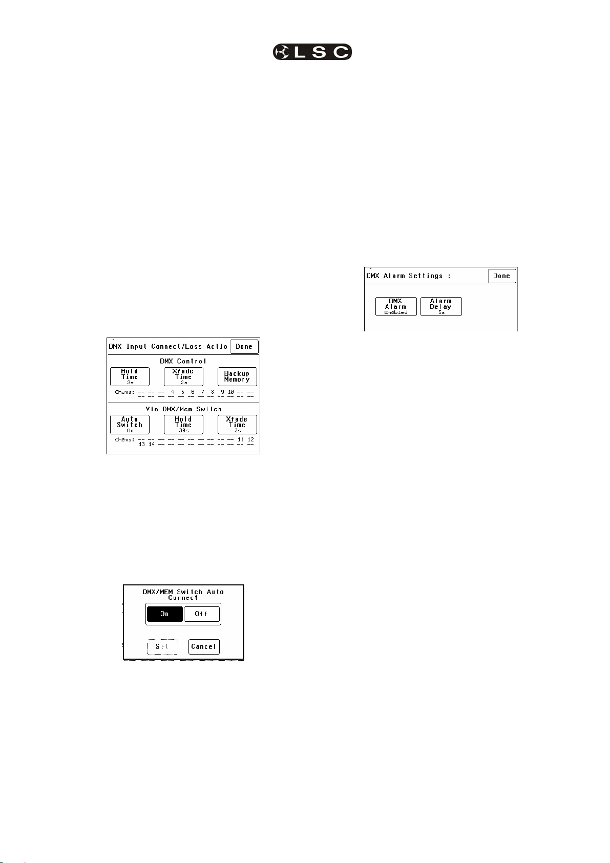
7.3.5 View Levels
The “View Levels” menu allows you to see the
levels of the DMX control signals that are
connected to the EKO dimmer.
Press [Menu] [DMX Input] [View Levels].
To select a channel, press that channel number.
You can add further channels to your selection
by pressing their channel numbers.
To deselect a channel, press it again.
To select a range of channels, press a channel,
then [Thru] then another channel.
To clear all
selections, press [Clr].
In the example above, dimmer 1 is patched to
DMX slot 1 and dimmer 9 is patched to DMX slot
2. Dimmer 16 is currently selected (white text on
black background) ready to be patched.
To make a patch, select the dimmer channel(s)
as described above then press [Patch].
Type in the DMX slot number then press;
[Patch @ Slot].
All of the selected dimmer channels are patched
to the selected DMX slot number.
Select other dimmers and patch them as
required.
To Un-patch a dimmer(s) select the dimmer(s)
then press [UnPatch].
When all patches have been made, press
[Done].
To save the patch, press [Save Patch] or to
cancel the changes that you have made and
return to the previous patch, press [Cancel].
7.3.4 Clear Patch
To remove all
patches in a single operation,
press [Menu] [DMX Input] [Patch] [Clear Patch]
[Yes].
The screen shows 32 (of the 512) DMX slots
and the level for each slot. Press [Next] or
[Prev] to change to the next or previous page of
32 DMX slots. The DMX values can be
displayed as a “%” (percentage), (0-100%) or as
“raw data” levels (0-255) by selecting the
relevant button at the bottom of the screen.
When finished, press [Done].
7.3.6 Connect Loss Action
This menu allows you to set the actions that the
EKO will take when a DMX signal is connected
(or restored after a loss). There are separate
settings for
• Dimmer channels whose “Control Source” is
DMX.
• Dimmer channels whose “Control Source” is
the output of the DMX/MEM Switch. See
“Control Source” earlier in this section for
details.
Press;
[Menu] [DMX Input] [Connect Loss Action].
The screen is divided into two sections;
• The top section sets the action for dimmer
channels under “DMX Control”. These
settings are described below. The screen
also shows the channels that are under
“DMX Control”. In the example above it is
channels 4 to 10.
• The bottom section sets the action for
dimmer channels controlled “via DMX/MEM
Switch”. Theses settings are described on
the next page. The screen also shows which
LSC Lighting Systems (Aust) Pty. Ltd Page 23
Page 28

Menus EKO Dimmer
Operator Manual V2.3
channels are under “DMXMEM Switch”
control. In the example above it is channels
11 through 14.
7.3.6.1 “DMX CONTROL” CONNECT
LOSS ACTION AND BACKUP MEMORY
In the event that the DMX input signal is lost, the
DMX controlled channels in the EKO can be
configured to respond in different ways.
The EKO can either HOLD the last valid DMX
levels indefinitely or, after a programmable
(hold) time, it can crossfade (Xfade) to a
“Backup Memory” stored in the EKO.
When DMX is restored, the EKO will
immediately crossfade (in the Xfade time) back
to the DMX signal.
Pressing [Hold Time] brings up a keypad screen
where you can enter a DMX hold time from 0 to
300 seconds (5 minutes) or you can select an
[Infinite] DMX hold time. After making your
selection press [Set].
After taking a snap you can still use the controls
on the screen to edit the “snapped” channel
levels as described below.
To set the level of a channel(s) it must be
selected. The selected channel(s) are indicated
by a small triangle (b) at the top of the screen
above the channel bargraph and are also listed
on the left of the screen. In the example below,
channel 11 is selected.
Selected Channel
There are two ways to select channels:
• Press [W] or [X] to step the small
triangle (b) through the channels.
• Press [Pick Chans] to reveal the
channel pick screen.
If a “Hold Time” other than “Infinite” has been
set, pressing [Xfade Time] allows you to enter a
time from 0 to 300 seconds (5 minutes) in which
the DMX channels will crossfade to the “Backup
Memory” (and back to DMX when it is restored).
Pressing; [Backup Memory] instantly replaces
the current output of all dimmer channels with
the contents of the Backup Memory. This is
irrespective of the “Control Source” settings for
the dimmer channels. The “Backup Memory”
screen allows you to either create your own
memory using the controls on the screen or take
a “snap” (copy) of the current DMX input signal
by pressing [Snap DMX].
If you press [Snap DMX] you must then choose
to take a snapshot of either “All” DMX channels
or only “Selected” channels. See below for
details on how to select channels.
To select a channel, press that channel number.
Selected channels have white text on a black
background.
You can add further channels to your selection
by pressing their channel numbers.
To deselect a channel, press it again.
To select a range of channels, press a channel,
then [Thru] then another channel.
To invert your selection(s) press [Inv]
To select all channels whose level is greater
than zero press [Lvl>0].
To clear all
selections, press [Clr].
When the required selections have been made
press [Pick] and the screen returns to the
“Modify Memory” screen.
When a channel(s) is selected it can be faded
up or down by sliding your finger on the virtual
fader.
To instantly set the fader to 0% press the [0%]
button below the fader.
Page 24
LSC Lighting Systems (Aust) Pty. Ltd
Page 29
EKO Dimmer Menus
Operator Manual V2.3
To instantly set the fader to 100% press the
[100%] button above the fader.
To quickly set the selected channel(s) to a
specific level press [@ Level]. Enter the level on
the keypad that appears then press [Set].
When the channel levels of the “Backup
Memory” are correct, press [Save Memory], or
to cancel the changes that you have made and
return to the previous Backup memory, press
[Cancel Memory].
When finished press; [Done] [Done]
[Done].
7.3.6.2 DMX/MEM SWITCH
CONNECT LOSS ACTION
touch screen by pressing [Menu] [Net Setup]
[DMX/MEM Switch].
Pressing [Hold Time] allows you to set the time
that the DMX/MEM Switch will remain in the
DMX position if the DMX signal is lost (if it has
been automatically operated by the presence of
a DMX signal). The Hold Time can be set from 0
to 999 seconds (over 15 minutes) or to Infinite. If
a “Hold Time” other than “Infinite” has been set,
the channels will crossfade to their current
“Memory” settings after the Hold Time expires.
7.3.7 DMX Alarm
Selecting [Menu] [DMX Input] [DMX Alarm]
reveals the following screen.
In the event that the DMX input signal is lost, the
“DMX/MEM Switch” can be configured to
respond in different ways.
Press;
[Menu] [DMX Input] [Connect Loss Action].
Pressing [DMX Alarm] allows you to “Disable” or
“Enable” the DMX alarm that occurs whenever
there is no valid DMX signal present.
The “DMX Alarm” is usually disabled in
installations that do not have a DMX input.
Pressing [Alarm Delay] brings up a keypad
screen where you can enter the delay time
Note: If [Auto Switch] is greyed out (not
available), then playback via LSCnet has
been disabled from the options menu. This
option can be selected when the EKO is
ONLY to be controlled by DMX. See “Options
Menu” for details.
Pressing [Auto Switch] allows you to turn “Auto
Switch” On or Off.
between when the EKO is turned ON and when
the “No DMX alarm” occurs. The time can be set
from 0 to 300 seconds or “infinite”.
Setting the “Alarm Delay” time to be slightly
longer than the “boot up” time of your DMX
lighting controller will prevent unwanted alarms
when both the EKO and Lighting Controller are
switched on at the same time.
7.4 MEMORIES MENU
Selecting [Menu] [Memories] provides menus
for;
• Recording Memories
• Editing Memories
• Copying Memories
• Deleting memories
An EKO dimmer can hold up to 80 memories.
Make your choice then press [Set].
If Auto switch is On, then if a valid DMX signal is
connected to the EKO, the DMX/MEM Switch
will operate and all dimmer channels whose
control source is set to “switch” will cross fade to
DMX control in the time set by the [Xfade Time]
button. This crossfade can be from 0 to 300
seconds (5 minutes).
Each memory only contains the intensity levels
for the dimmer channels that you select when
you record (or edit) that memory. If a channel is
not selected in a memory then recalling that
memory will never affect that channel. Selected
channels in a memory can have any level from
0% to 100%.
Memories are recalled from ePlate wall stations.
7.4.1 Recording Memories
Press: [Menu], [Memories].
Note: The DMX/MEM Switch can also be
manually operated from either a suitably
programmed ePlate button or from the LCD
LSC Lighting Systems (Aust) Pty. Ltd Page 25
Page 30
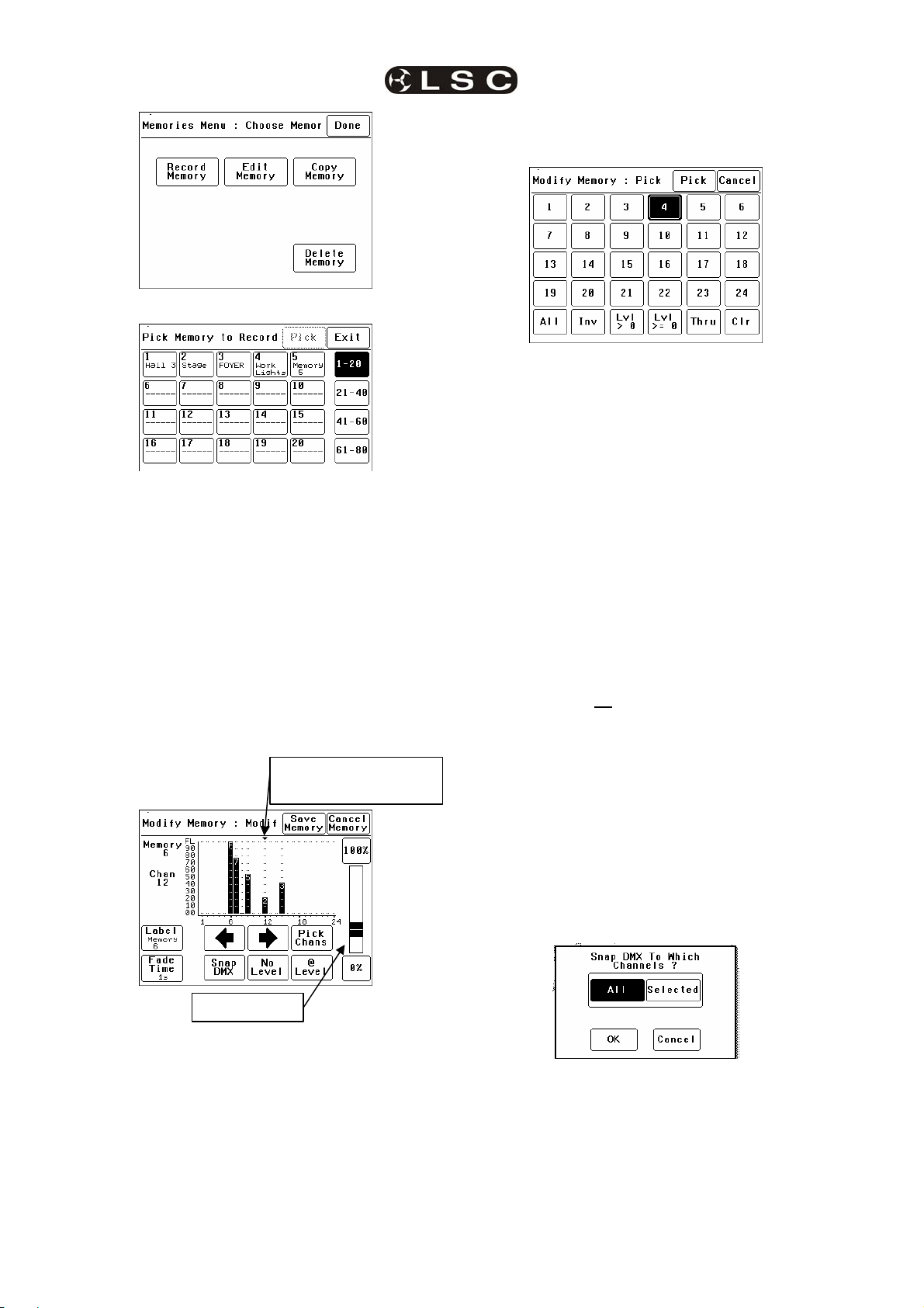
Menus EKO Dimmer
(s)
Operator Manual V2.3
• Press [Pick Chans] to reveal the
channel pick screen.
To record a memory press:
[Record Memory].
The current output of the EKO dimmer (if any) is
blacked out.
The memories are organised in 4 banks of 20
memories. The buttons on the right select the
banks. Select the bank and memory number to
be recorded. When a memory is selected its
contents are shown on the output of the EKO
and also on the channel indicators. This allows
you to preview the contents of memories on the
output and either pick an empty or existing
memory.
To confirm your selection press [Pick].
If the memory exists, it will be deleted. To
confirm press [Yes].
▼ indicates selected
channel
• To select a chann el, press that channel
number. Selected channels have white
text on a black background.
• You can add further channels to your
selection by pressing their channel
numbers.
• To deselect a channel, press it again.
• To select a range of channels, press a
channel, then [Thru] then another
channel.
• To invert your selection(s) press [Inv]
• To select all channels with a level
greater than zero press [Lvl > 0].
• To select all included channels
(including those with level of zero) press
[Lvl > = 0]. See “How Memories Work”
for details on included channels with a
level of zero.
• To clear all
selections, press [Clr].
When the required selections have been made
press [Pick] and the screen returns to the
“Modify Memory” screen.
To set the level of the selected channel(s) either:
• Slide the virtual fader
• Press the [0%] or [100%] buttons.
• Press [@ Level] and enter a value.
Channel levels can also be set using the DMX
input from a lighting controller. Press [Snap
DMX] to take a snapshot of the DMX input
signal.
Virtual fader
To vary the level of a channel it must be
selected. The selected channel is shown below
the memory number and also indicated by small
triangle (b) above the selected channel(s). In
this example channel 12 is selected.
There are two method to select channels:
• Press [§] or [¨] to step (b) through the
channels.
Page 26
If you do not want to capture the level of all
channels you can use the “selected” option to
only include the levels of the channels that you
have selected. See “Included Channels” below.
7.4.2 Included Channels
If a channel is not included in a memory then
the channel is not affected when that memory
is faded up or down.
LSC Lighting Systems (Aust) Pty. Ltd
Page 31
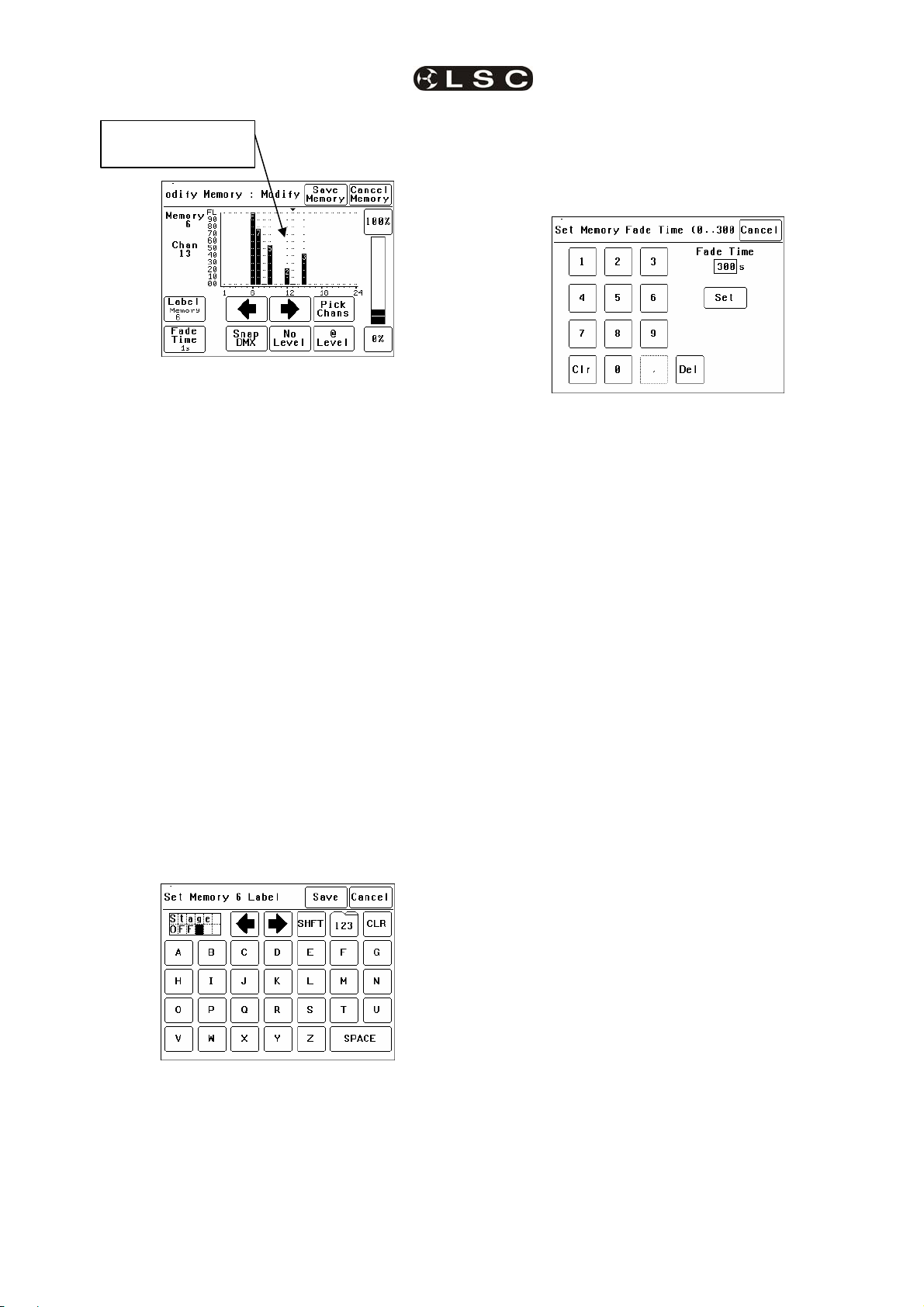
EKO Dimmer Menus
Operator Manual V2.3
Grid Marks show
included channels
7.4.2.2 FADE TIME
The default Fade time for each memory is 1
second.
You can set your own fade time by pressing
[Fade Time].
A memory only contains the channels that you
select. Selected channels can have any level
including zero.
When a memory is recalled, only channels that
are in the memory are affected. If a channel is
not in a memory, its current level (if any) will not
be affected when that memory is recalled.
Note: This is a very important concept.
It is fully explained in section 8.3 How
Memories and Zones Work.
You can see which channels are included in a
memory by the grid marks above the channels.
In the example above, channel 6 to 9, 12, 13
and 15 are included. Note that channel 13 is
included but has a level of 0%.
Channels 1 to 5, 10, 11 and 16 to 24 are not
included in this memory.
If you have included a channel (by giving it a
level) and then decide to remove it from the
memory then you must select the channel and
press [No Level].
7.4.2.1 MEMORY LABELS
The default label for each memory is its number.
For example, “Memory 6”.
You can enter your own label by pressing
[Label].
A memory may have a fade time in the range 0
to 300 seconds (5 minutes). A time of less than
10 seconds may in the range 0.0 to 9.9 seconds.
From 10s the time is in increments of 1second.
When the fade time is correct press [Set].
Note: An ePlate button can be programmed
to replay a memory using the time saved in
the memory or the button can have its own
specific fade time. In this case the memories
fade time will be ignored.
To save the memory press;
[Save Memory] [Exit].
The original dimmer output is restored.
7.4.3 Edit Memory
To edit a memory press:
Press: [Menu], [Memories] [Edit Memory].
The current output of the EKO dimmer (if any) is
blacked out.
Select the memory to be edited. As each
memory is selected its contents are shown on
the output of the EKO and also on the channel
indicators. This allows you to preview the
contents of each memory on the output.
To confirm you selection press [Pick].
Editing a memory is the same as recording a
memory.
See section 7.4.1 Recording Memories for
details.
7.4.4 Copy Memory
To copy a memory press:
Press: [Menu], [Memories] [Copy Memory].
The current output of the EKO dimmer (if any) is
blacked out.
Select a “source” memory to be copied. As each
Pressing [CLR] clears the current label. Press
[§] or [¨] to move the flashing cursor then
select the letters or press [123] to select
numbers. Press [Shift] for uppercase letters or
symbols instead of numbers.
When finished press [Save].
LSC Lighting Systems (Aust) Pty. Ltd Page 27
memory is selected its contents are shown on
the output of the EKO and also on the channel
indicators. This allows you to preview the
contents of each memory on the output and
make the correct choice.
When the correct source memory is selected
press [Pick].
Select a “destination” memory number then
press [Pick].
Page 32

Menus EKO Dimmer
Operator Manual V2.3
You can copy more memories or if finished
press [Exit], [Done] [Done].
7.4.5 Delete Memory
To delete a memory press:
Press: [Menu], [Memories] [Delete Memory].
The current output of the EKO dimmer (if any) is
blacked out.
Select a memory to be deleted. As each
memory is selected its contents are shown on
the output of the EKO and also on the channel
indicators. This allows you to preview the
contents of each memory on the output and
You can set the DMX/MEM Switch in each EKO
to only be operated by a particular “Switch
Group Number”.
Therefore, in setups with more that one EKO,
individual ePlate buttons can be programmed to
only operate the DMX/MEM Switch in EKO
dimmers with the matching “Switch Group
Number”.
To set the “Switch Group Number”, from the
“Net Setup” menu (above) press;
[Switch Group Number].
make the correct choice.
When the correct memory to be deleted is
selected, press [Pick]. To confirm, press [Yes].
You can delete more memories or if finished
press [Exit], [Done] [Done].
7.5 NET SETUP MENU
The “Net Setup” menu is used to control the
manual operation of the DMX/MEM Switch.
Press; [Menu], [Net Setup].
Note: If [Net Setup] is greyed out (not
available), then playback via LSCnet has
been disabled from the options menu. This
option can be selected when the EKO is only
Enter the required Switch Group Number in the
range from 001 to 255 (to match the required
ePlate button) or for no Switch Group press
[Disabled], then press [Set] [Done] [Done].
to be controlled by DMX. See “Options
menu” for details.
7.6 OPTIONS MENU
Selecting [Menu] [Options] provides menus for;
• Module Status
• Beeper
• About
• Lock Dimmer
• Change Lock Code
7.5.1 DMX/MEM Switch Operation
All channels that have their “Control Source”
attribute set to “Switch”, can be switched
between either “DMX” control or “Memory”
(ePlate) control.
The DMX/MEM Switch can be operated from a
suitably programmed button on an ePlate or
directly from the LCD touch screen on the EKO.
To manually operate the “DMX/MEM Switch”
from the touch screen, press;
[Menu], [Net Setup] [DMX/MEM Switch].
• Dimmer Name
• Date and Time
• Net Playback: Enable/Disable
• Reset
7.6.1 Module Status
Depending upon the model of your EKO it may
contain one or two internal modules.
Pressing [Menu] [Options] [Module Status]
reveals information about the input power
phases, temperature and fan speed of the
internal dimmer module(s) of the EKO.
.
Select either; [DMX] or [Memory] then press
[Set].
7.5.2 Switch Group
An ePlate button that has been programmed to
operate the DMX/MEM Switch can also be
programmed with a “Switch Group Number”.
Page 28
EKO model with 2 Modules.
LSC Lighting Systems (Aust) Pty. Ltd
Page 33

EKO Dimmer Menus
Operator Manual V2.3
7.6.6 Name
The name of each EKO dimmer is shown on the
home screen of the LCD touch screen. The
default name is EKO Dimmer but you can give
the dimmer a name of your choice. Naming each
dimmer is useful in installations of more than
one EKO. To change the name of a dimmer
press;
[Menu] [Options] [Dimmer Name].
EKO model with 1 Module.
7.6.2 Beeper
The EKO can be set to “Beep” in
acknowledgment to every key press on the
touch screen.
To switch off the beeper, press; [Menu]
[Options] [Beeper is On].
To switch on the beeper, press; [Menu] [EKO]
[Beeper is Off].
7.6.3 About
Pressing [Menu] [Options] [About] reveals
information about the software version, model
and voltage of the EKO.
To start a new name press [CLR]. Use the § or
¨buttons to move the flashing cursor Type in
your name. For numbers press [123]. When
finished press [Save] [Done] [Done].
7.6.4 Lock / Unlock
To lock the touch screen of the EKO and
prevent unauthorised access press [Menu]
[Options] [Lock Dimmer].
The EKO keeps a log of its status that is time
and date stamped. To set the time and date
used by the log press;
[Menu] [Options] [Date & Time].
7.6.7 Time and Date
The screen shows the current time and date
settings.
To change the Time, press [Time]. Use the
keypad that appears to enter the time in 24 hour
format then press [Set].
To change the Date, press [Date]. Use the
keypad that appears to enter the date then press
[Set].
When finished press [Done].
Using the keypad, type in the current 4 digit lock
code then press [Lock]. The EKO is shipped
from the factory with the lock code set to 0000.
The menu returns to the home screen and the
[Unlock] button appears instead of the [Menu]
button.
To unlock the touch screen of the EKO press
[Unlock] then type in the current 4 digit code
then press [Unlock].
7.6.5 Change Lock Code
To change the lock code, press [Menu]
[Options] [Change Lock Code].
Type in the current 4 digit lock code then press
[Enter]. (The EKO is shipped from the factory
with the lock code set to 0000).
Type in your new lock code then press [Enter].
To confirm, re type the new lock code then press
[Set Code].
If the EKO is only to be controlled by DMX then
it is possible to disable (dim out) all memory
menus and other network functions and hence
simplify the menu operations. In addition, when
“Net Playback” is disabled, all dimmer channels
are controlled by DMX, irrespective of their
previous “Control Source” settings.
Press [Menu] [Options] [Net Playback].
Choose either [Enable] or [Disable] then press
[Set].
The EKO provides two different types of reset
function. SYSTEM reset and TOTAL reset.
In the unlikely event that the EKO fails to
respond, the operating system may be reset so
that the software may initialise and recommence
normal operation. Performing a system reset will
not affect any of the settings or memory.
7.6.8 Net Playback
7.6.9 Reset
7.6.9.1 SYSTEM RESET
LSC Lighting Systems (Aust) Pty. Ltd Page 29
Page 34
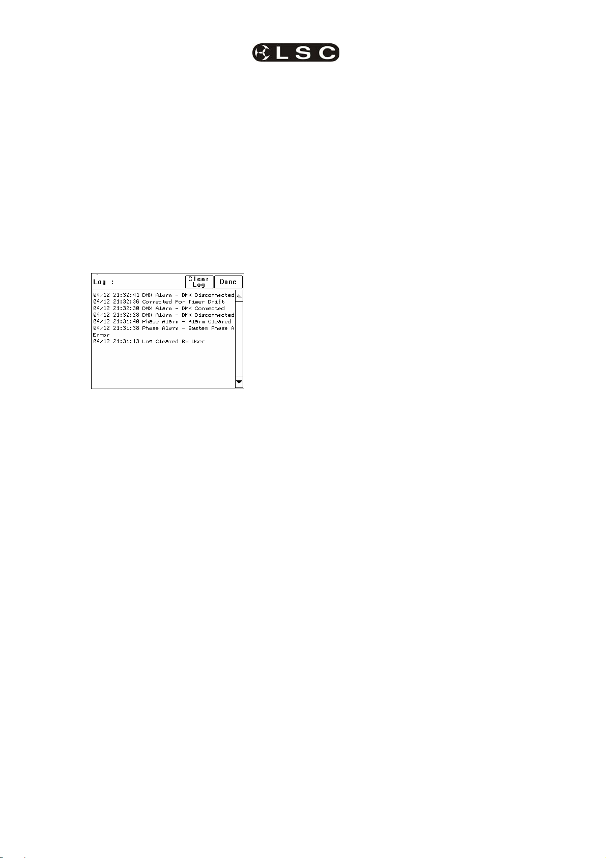
Menus EKO Dimmer
Operator Manual V2.3
To perform a SYSTEM RESET press;
[Menu] [Options] [Reset] [System Reset]
[Yes].
7.6.9.2 TOTAL RESET
Total Reset will ERASE all the settings and
memory from the EKO and reset the operating
system.
To perform a TOTAL RESET press;
[Menu] [Options] [Reset] [Total Reset] [Yes].
The EKO asks you to confirm by pressing [Yes]
again.
7.7 LOG MENU
Selecting [Menu] [Log] shows the status log
showing time and date stamped operations and
alarms.
The log can be used to analyse any problems
you may have encountered such as loss of
control signals, over temperature alarms or loss
of input power phases etc.
Page 30
LSC Lighting Systems (Aust) Pty. Ltd
Page 35

EKO Dimmer
Operator Manual V2.3
8 Memory (ePlate) Control
Note: If Net Playback functions are disabled,
the Memories and Net Setup buttons in the
EKO Menu are dimmed, and ePlates will not
function. See section 7.6.8 Net Playback for
details.
• ePlate active or locked.
• DMX or Memory control selected.
8.1.2 Faders
A fader can be configured to:
• Control the level of a memory (or channel).
• Act as a Grand Master over all channels.
8.1 EPLATES FUNCTIONS
There are two types of controls on an ePlate:
• Act as Group Sub Master over the memory
levels of channels in that group number.
• Set the Fade Time for a memory.
8.2 MEMORIES:
Memories are recorded (or edited) from the
EKO’s LCD touch screen.
Memories are recalled from ePlate wall stations.
An EKO dimmer can hold up to 80 memories.
Each memory only contains the intensity levels
for the dimmer channels that you select when
you record (or edit) that memory. If a channel is
not selected in a memory then recalling that
Buttons Faders
ePlates are available with 2, 4 or 8 buttons or 1,
2 or 4 faders.
8.1.1 Buttons
Each button has an associated indicator. The
button and indicator can be independently
configured.
A button can perform any of the following
actions:
• Activate a memory with a specific fade time
and level.
For example;
Button 1 might set memory 5, to 100%
level with a fade time of 10 seconds.
Button 2 might set memory 5, to 50%
level with a fade time of 5 seconds.
Button 3 might set memory 5, to 0%
level with a fade time of 15 seconds.
• Control multiple memories from a single
button.
• Switch dimmer channels between DMX and
Memory (ePlate) control (if the channel’s
“control source” has been set to “switch”).
• Lock / unlock the operation of other ePlates.
• A single button might perform multiple
commands.
For example;
A button could be configured for “Emergency
Evacuation”. When pressed, it would change
the EKO to Memory Mode, then turn all the
lights on at 100% and then lock all other
ePlate wall stations so that the lights cannot
be turned off.
The indicators beside each button are
independently programmed and can indicate
any of the following:
• Memory # activated. Brightness of indicator
shows level of memory.
LSC Lighting Systems (Aust) Pty. Ltd Page 31
memory will never affect that channel. Selected
channels in a memory can have any level from
0% to 100%.
Memories are recorded (or edited) by either;
• Selecting channels and giving them a
level via the touch screen controls.
or
• Taking a ‘snapshot’ of the current DMX
input levels. These levels can then be
edited if required.
See section 7.4 Memories Menu for details on
how to record memories.
Each memory controls the dimmer channels
contained in that EKO (either 6, 12 or 24
channels, depending upon the EKO model). This
allows each EKO dimmer to store different
channel memory information whilst using the
same memory numbers as other EKO dimmers
in the same LSCnet system. Controlling a
memory number via an ePlate will make each
EKO dimmer on the LSCnet set its channels
according to its own memory settings.
ePlate buttons send commands in the form of
“Set Memory # to level # in # seconds”.
For example, memory 2 contains channels 1
and 2 at 100% and channel 5 at 60%. It could be
recalled in different ways by programming 3
ePlate buttons.
• A button programmed to Set Memory 2
to 100% level in 2 seconds will fade
channels 1 and 2 to 100% and channel
5 to 60%
• A button programmed to Set Memory 2
to 0% level in 0 seconds will instantly
turn off channels 1, 2 and 5.
Page 36

Memory Control EKO Dimmer
Operator Manual V2.3
• A button programmed to Set Memory 2
to 50% level in 10 seconds will slowly
fade channels 1 and 2 to 50% and
channel 5 to 30%
Memories can also be manually controlled by
suitably programmed ePlate faders.
8.3 HOW MEMORIES & ZONES WORK
When a memory is recalled (faded up or down),
it only affects the channels that are included in
that memory.
A new (empty) memory does not contain any
channels.
To include a channel in a memory, select the
channel then give it a level (0% to 100%). Note
that the level of an included channel can be 0%.
To remove a channel from a memory, select the
channel then press [No Level].
Setting a channel to 0% does NOT remove it
from the Memory.
Vertical grid marks
show channel is
included in memory.
just faded up. Only the channels in the memory
will change. Any channels that are not in the
new memory will remain as they were.
Note: This is different to some lighting
controllers that “crossfade” from one
memory to another. In a “crossfade”, the
incoming memory totally replaces the
outgoing memory.
This method of memory operation makes the
EKO very powerful as described below.
8.3.1 Zones
The EKO’s method of memory operation allows
for complete flexibility of zone control when
recalling memories.
Each memory can contain any number of
channels from 1 to 24. A zone is created by
recording a memory that only contains the
channels located in that zone.
For example;
Zone 1 has channels 1 to 12 located in it.
We might use memories 1 to 5 for zone 1.
Memories 1 to 5 are recorded with only channels
1 to 12 in them.
Zone 2 has channels 13 to 24 located in it.
We might use memories 6 to 10 for zone 2.
Memories 6 to 10 are recorded with only
channels 13 to 24 in them.
The memories for each zone are totally
separate. Recalling memories 1 to 5 will never
affect zone 2 because channels 13 to 24 are not
contained in these memories.
Likewise, recalling memories 6 to 10 will never
affect zone 1 because channels 1 to 12 are not
This menu of a 6 channel EKO dimmer shows a
Memory containing four channels. Channels 1
and 2 are at full. Channels 3 and 4 are at 0%.
Channels 5 and 6 are not in the Memory. This is
shown by the absence of “grid marks” above
these channels.
If this memory was saved and faded up it would
set 1 and 2 to full, 3 and 4 to 0% and have no
effect on the current state of 5 and 6.
When this memory is faded down, channels 1, 2,
3 and 4 will all fade to 0% but channels 5 and 6
would not be affected.
If a channel is not included in a memory then
the channel is not affected when that memory
is faded up or down.
This is an important concept.
It means you have to decide whether or not you
want a channel to be in a memory. Fading up a
memory will not necessarily replace the current
contained in these memories.
The EKO memory system is far more flexible
than normal architectural zone systems,
because it is also possible to have memories
that control all the channels, thus creating a
master zone memory.
For example; memories 11 to 14 might contain
channel 1 to 24. These memories control all
zones.
There is no limit to the number of ‘zones’ and
‘master zones’ that can be controlled in this
manner.
8.3.2 Controlling Memories
Memories are recalled by ePlates buttons or
faders.
ePlates are configured by a software application
so that each button or fader sends a specific
command. ePlates are shipped from the factory
with the most common commands preprogrammed into them.
See section 8.6 “Pre Programmed ePlates”.
output of the dimmer with the memory you have
Page 32
LSC Lighting Systems (Aust) Pty. Ltd
Page 37

EKO Dimmer Memory Control
Operator Manual V2.3
The typical command to control a memory
The result is:
is……..
“Fade Memory Number # to Level #% in Time #”
When this message is received by the EKO, it
will fade the channels listed in the Memory
Number to the levels in that Memory, scaled by
the Level #%. The time taken can be either a
value in seconds or an instruction to use the
time saved in the Memory.
Therefore, the same memory can be recalled at
different levels from different buttons.
• One button might fade up the memory to
full level.
To fade DOWN memory 1, the message “Fade
Memory 1 to Level 0% in time 1s” is sent.
Channels 1, 2 and 3 will fade to 0%.
The result is:
• Another might fade the same memory to
half level.
• Yet another button might fade the same
memory off. This would be achieved by
sending a command to playback the
memory with its Level at 0%.
8.3.3 Simplified Memory Playback
Example:
Assume that the current output looks like this. All
channels of a 6 channel dimmer are at 24%.
8.3.4 LTP (Latest Takes Precedence)
When a memory is played back, each dimmer
channel contained in the memory is set to its
level in that memory. When another memory is
played back, if the same channel is in that
memory, then it goes to its level in this latest
memory, even if the previous memory is still
faded up. The “latest” memory takes
precedence.
Lets playback Memory 1 which has the following
levels….
When a memory is played back, the memory is
marked as “Active” and a command is sent to
the ePlates to light the relevant indicator in the
8.3.5 Active Memories
button.
As other memories are recalled, they may turn
off channels that were part of this “active”
memory. There may come a point where none of
the dimmer channels in the original memory are
on, even though there has not been a command
to turn off this memory. When this happens, the
dimmer sends a message that the Memory has
Channel 1 is at 100%. Channel 2 is at 50%.
Channel 3 is at 0%. Channels 4, 5 and 6 are not
in the Memory (no grid lines above them).
To fade UP memory 1, the message “Fade
Memory 1 to Level 100% in time 1s” is sent from
an ePlate. Channels 1,2 and 3 will fade to their
recorded levels in 1 second. Channels 4 to 6 are
not affected.
been “Released”.
The result of this is that an indicator on an
ePlate for a particular Memory will remain lit so
long as at least one channel in that Memory is
still active on an EKO.
8.4 FADE TIMES
When an button ePlate is configured, you can
choose to set a fade time for that button or use
the default time held in the memory.
Therefore different buttons can recall the same
memory but use different fade time.
When an ePlate fader is moved, the memory it is
controlling is told to fade to the level associated
with the new fader position. The fader may be
configured with a specific fade time, or to use
LSC Lighting Systems (Aust) Pty. Ltd Page 33
Page 38

Memory Control EKO Dimmer
Operator Manual V2.3
the fade time associated with the memory it is
controlling. Setting a fade time of zero seconds
results in the memory directly tracking the fader
as it moves. LSC suggests that manual faders
be programmed with a fade time of 0.5 seconds.
This results in a much smoother fade as the
fader is moved.
8.5 MEMORY RECOVERY AFTER
POWER LOSS
When power is restored to an EKO after a
power loss, channels controlled by DMX will
immediately respond to the current DMX levels.
However, channels controlled by Memories
respond differently depending upon the duration
of the power loss.
• If the power returns within 2 hours, the
memory channels will return to their last
memory levels.
• If the power returns after 2 hours, memory
channels will remain OFF. To restore output
you must recall the required memory.
8.6 PRE-PROGRAMMED EPLATES
ePlates are available from the factory with preprogrammed configurations to control memories
or operate the “MEM/DMX” switch.
8.6.1 Memory Control ePlates
Pre-programmed ePlates to control memories
are available in the following configurations…
• 2 Button ePlates
Button 1 recalls Memory 1 at 100%
Button 1 selects DMX
Button 2 selects Memory
8.7 RECORDING MEMORIES FOR
PRE-PROGRAMMED EPLATES
The factory pre-programming of the ePlate
buttons is designed for simple and predictable
memory programming.
The buttons on the “Pre-Programmed” ePlates
all recall a different memory number at full level.
Question: If every button recalls a memory at
full level, how do you turn a memory off?
Answer: You playback a different memory
containing the same channels but with their
levels set to 0% in that memory.
When a memory is recorded, it contains
selected channel(s) at any level (including zero
level). Therefore, if memory 1 contains channels
at a level of 80%, pressing button 1 on an ePlate
will fade up those channels to 80%.
If memory 2 contains the same channels at a
level of 0%, pressing button 2 on an ePlate will
fade those channels off.
For example;
Button 1 recalls Memory 1
which contains channels
1, 3 and 6 at various
levels.
Button 2 recalls Memory 2 at 100%
• 4 Button ePlates
Button 1 recalls Memory 1 at 100%
Button 2 recalls Memory 2 at 100%
Button 3 recalls Memory 3 at 100%
Button 4 recalls Memory 4 at 100%
• 8 Button ePlates
Button 1 recalls Memory 1 at 100%
Button 2 recalls Memory 2 at 100%
Button 3 recalls Memory 3 at 100%
Button 4 recalls Memory 4 at 100%
Button 5 recalls Memory 5 at 100%
Button 6 recalls Memory 6 at 100%
Button 7 recalls Memory 7 at 100%
Button 8 recalls Memory 8 at 100%
• 1 Fader ePlates
Fader 1 controls Memory 1
• 2 Fader ePlates
Fader 1 controls Memory 1
Fader 2 controls Memory 2
• 4 Fader ePlates
Fader 1 controls Memory 1
Fader 2 controls Memory 2
Fader 3 controls Memory 3
Fader 4 controls Memory 4
8.6.2 Memory/DMX Switch ePlates
Button 2 recalls Memory 2
which also contains
channels 1, 3 and 6 but all
at a level of 0%.
Using this method, each pair of buttons on a
pre-programmed ePlate are easily used as ON
(fade up) and OFF (fade down) buttons. You
record the odd numbered memories with the
levels you require. You record the even
numbered memories with the same channels at
a level of 0%.
For example, after you record memory 1, record
memory 2 with the same channels as used in
memory 1 but with their levels set to 0%.
After you record memory 3, record memory 4
with the same channels as used in memory 3
but with their levels set to 0%.
Contact LSC or your LSC agent if you have
special ePlate requirements that cannot be
achieved with the pre-programmed ePlates. LSC
will then custom program your ePlates for your
specific requirements.
A pre-programmed 2 button ePlate is available
to control the operation of the Memory/DMX
Switch.
Page 34
LSC Lighting Systems (Aust) Pty. Ltd
Page 39
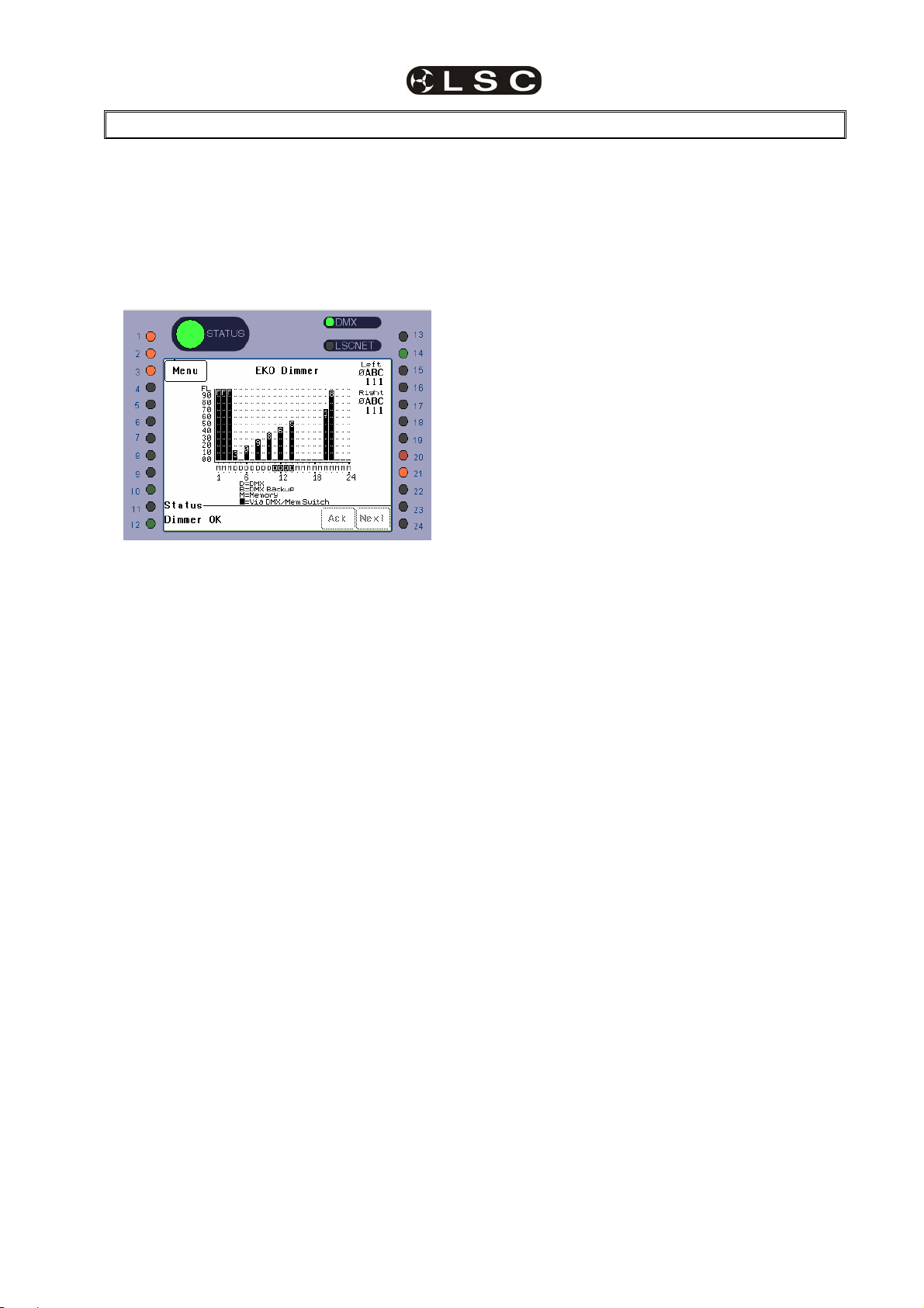
EKO Dimmer
Operator Manual V2.3
9 Alarms and Troubleshooting
Warning. No user controls or user serviceable
parts are located inside the EKO Dimmer. Refer
all servicing to suitably qualified personnel.
The only routine maintenance for the EKO
Dimmer is to periodically ensure that the air
vents at the top and bottom of the frame are free
from dust.
If the EKO is not functioning correctly, check the
LED indicators on the front panel and the status
area at the bottom of the LCD screen for any
messages.
9.1 STATUS LED
• Green = Normal operation.
• Red (flashing) = Alarm. See message
on LCD touch screen.
• Red (steady) = Alarm is acknowledged
but the problem still exists.
Possible causes of a flashing Status LED are;
• Over Temperature.
There is one temperature sensor for
dimmers 1 to 12 and another temperature
sensor for dimmers 13 to 24. If the temperature
of the EKO is too high, the circuitry automatically
switches off the bank of dimmers with the high
temperature. All affected dimmer channels will
flash red. Either reduce the load or increase the
cooling to the EKO. When the temperature
returns to normal, the EKO automatically returns
to normal operation.
• Temperature sensor failure.
If either of the temperature sensors fail,
the circuitry automatically switches off the
affected bank of dimmers. All affected dimmer
channels will flash red.
• Loss of input power phase(s).
If any of the input power phases are lost,
the affected dimmer channel LEDS will flash red.
In the event of any alarm, read the message on
the status area of the LCD screen. Press [Ack]
on the touch screen to Acknowledge the alarm.
This stops the status LED from flashing but it
remains red until the fault condition is rectified.
9.2 DMX LED
• Green = Valid DMX control signal
connected.
• Red (flashing) = Error on DMX control
signal.
• Green (flashing) = Loss of DMX control
signal.
If the DMX LED is flashing RED, the EKO
Dimmer has detected an error in the DMX
control signal. Try connecting the EKO Dimmer
to a known good DMX controller via the existing
DMX distribution installation. If the LED turns
green, the DMX controller is faulty.
If the DMX LED is flashing Green, the EKO
Dimmer is not receiving a DMX control signal.
Check that the lighting control desk is ON and
sending a DMX output. Also check that any
DMX splitters in the installation are working
correctly and that all DMX cables are intact.
9.3 LSCNET LED
• Green = Valid LSCnet control signal
connected (from ePlates).
• Green (flashing) = Data traffic detected
on LSCnet.
9.4 CHANNEL LEDS
The numbered LED’s around the perimeter of
the control panel light when their respective
dimmer channel is on. The brightness of the
LED shows the channel level.
• They light green when under DMX
control.
• They light red when under local control.
If a dimmer channel is not working check the
MCB (Miniature Circuit Breaker) for that dimmer
channel.
If the MCB has tripped (OFF), firstly try to
determine the cause of the breaker tripping. It
could be a blown lamp or a circuit overload.
Rectify to problem (replace the lamp or reduce
the load) then restore the MCB. If the MCB
continues to trip, refer the problem to a suitably
qualified person.
If the MCB has not tripped, you can test the
operation of the dimmer from the local LCD
touch screen. See section 3.1.1.2 “Channel
Test” for details. If the dimmer is working from
the touch screen but not via DMX (remote),
check that the dimmer is patched to the correct
DMX slot and correctly configured. See section
3.1.2.1 “Patching Basics” for details.
LSC Lighting Systems (Aust) Pty. Ltd Page 35
Page 40

Alarms and Troubleshooting EKO Dimmer
Operator Manual V2.3
9.5 TROUBLESHOOTING
Fault. My ePlate is dead.
Solution. The ePlate receives it power via the
LSCnet cable, so it could be a faulty cable or a
faulty LSCnet PSU in the EKO dimmer rack.
To locate the problem check the status of the
LSCnet Datalink LED’s
dimmer is still not reacting then it is a problem
with the dimmer configuration.
Check the following;
1) Does the memory that is being recalled by the
ePlate have the correct channels saved in it? If
not, save the correct channel levels in the
memory
2) Are the channels configured for Memory
control? If not, change the dimmer channels
control source to Memory.
On the EKO Dimmer, the led is marked Data
Link, and is located just above the Touch
Screen. The EKO door must be opened to see
the LED
Data Link
LED
On the ePlate the Data Link led is located on the
back of the main circuit board. It will only be
visible during installation.
Data Link
LED
With everything turned on, make sure that all of
these LED’s are GREEN. If any LED is not lit,
then there is no power getting to that device.
Check the cables for bad connections.
Fault: My ePlate is responding to button
presses, but the EKO dimmer is not responding.
Solution. Check the LSCnet Datalink LED’s on
the ePlate (see above). Whenever you press a
button the LED should flash Orange for a
moment and then return to the normal Green
state. If the LED always stays Green, then the
ePlate is not operating correctly.
If the ePlate is working correctly then check the
LSCnet Datalink LED on the EKO dimmer. It
should also flash Orange whenever you press a
button on the ePlate. If not then there is a cable
fault between the dimmer and the ePlate. Check
and repair the cable.
If the Datalink LED does flash orange, then
dimmer is receiving the message ok. If the
Page 36
LSC Lighting Systems (Aust) Pty. Ltd
Page 41
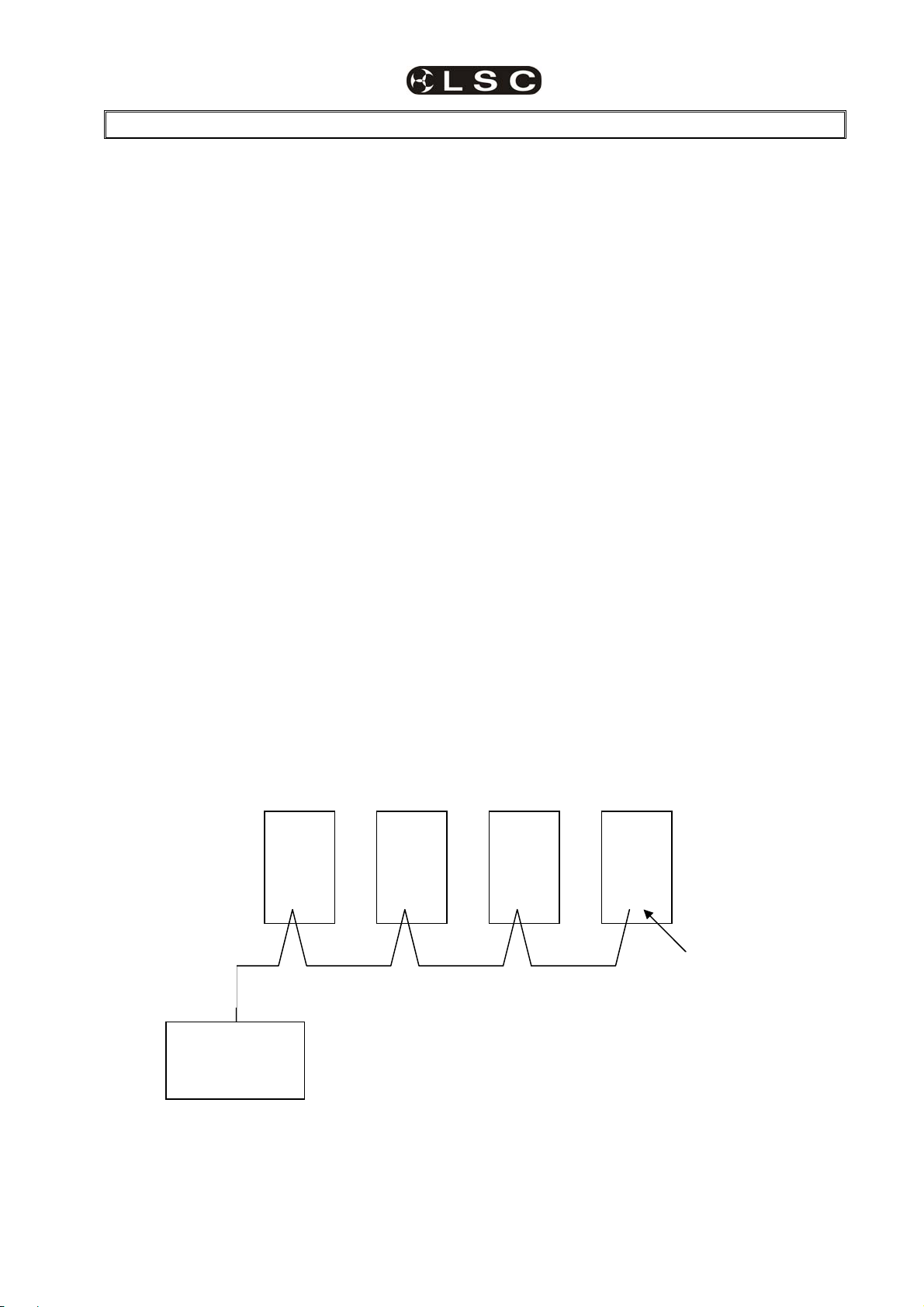
EKO Dimmer
Operator Manual V2.3
10 DMX Explained
DMX512/1990-A is the industry standard for the
transmission of digital control signals between
lighting equipment. It utilises just a single pair of
wires on which is transmitted the level
information for the control of up to 512 DMX
slots (addresses or channels).
The information for each slot is sent
sequentially. The level of slot 1 is transmitted,
then the level of slot 2, then 3, etc. up to a
maximum of 512 slots. This stream of data
containing the levels for all 512 DMX slots is
repeated a minimum (generally) of 44 times per
second. This provides sufficient updates of
channel information for smooth fade transitions.
As the DMX512-A signal contains the level
information for all slots, each piece of equipment
needs to be able to read the level(s) of the
slots(s) that apply only to that piece of
equipment. To enable this, the EKO dimmer has
a “DMX Patch” menu that allows you to patch
(connect) each DMX slot (address) from your
lighting controller to an EKO dimmer channel
number or to multiple dimmer channel numbers.
When good quality data cables are used,
DMX512 cable runs may be up to 1,000 metres
in length. When several DMX feeds are required
(to feed different locations), DMX512 splitters
must be used. These provides multiple isolated
DMX512 feeds.
The EKO uses a high impedance DMX input
circuit allowing you to loop the DMX signal from
one EKO to the next. The last EKO in the chain
must have the “DMX Terminate switch” set to
TERM to terminate the line.
Note: Do not use unscreened microphone or
low speed data cables for DMX. This can cause
problems in the DMX network. Make sure the
cable conforms to the EIA485 cable
requirements by providing the following
specifications:
• Low capacitance
• One or more twisted pairs
• Foil and braid shielded
• Impedance of 85 -150 Ohms, nominally 120
Ohms
• 22AWG gauge for continuous lengths over
300 metres
The following diagrams illustrate some simple
setups utilising DMX512.
10.1 TYPICAL DMX INSTALLATIONS
In the following example, the DMX output signal
from the lighting control desk is fed to the DMX
connector of the first EKO dimmer. The DMX
cable is then looped to the following EKO
dimmers. The order of the daisy chaining is not
important as each EKO dimmer channel can be
patched to any DMX slot number. The end of the
DMX line is terminated to prevent the signal
reflecting back up the line and causing possible
errors.
EKO
DMX
Slots
61-66
Termination
Switch set
DMX
Cable
Lighting
Controller
EKO
DMX
Slots
1-24
EKO
DMX
Slots
25-48
EKO
DMX
Slots
49-60
In the next example, the DMX is first fed to a DMX splitter which isolates the outputs. Separate DMX
cables are then run to the various locations where the EKO’s are installed. In the event of a fault on one
of the cables, the other outputs from the splitter will not be affected.
LSC Lighting Systems (Aust) Pty. Ltd Page 37
Page 42

DMX Explained EKO Dimmer
Operator Manual V2.3
Other DMX
controlled
equipment
DMX
splitter
DMX 512
OUTPUT
EKO EKO
DIMMERS
DIMMERS
1 TO 12
1 TO 12
TERMINATION
ON
Lighting
Controller
EKO
1
EKO
TERMINATION
ON
EKO
Page 38
LSC Lighting Systems (Aust) Pty. Ltd
Page 43

EKO Dimmer
Operator Manual V2.3
11 FAQ
11.1 FREQUENTLY ASKED
QUESTIONS
Q. How do the EKO’s go with a load such as a
mirror balIs. Is there any trickle?
A. No problems. We use a circuit called PTFD
(Pulse Transformer Fired Dimming), which
means that we can control virtually ANY type of
load (Resistive, Inductive, Strobes, Motors, ELV,
etc), without the need for dummy loads. This is
one of the key differences between LSC and
most other brands of dimmers.
Q. Do the dimmers work on HTP or LTP when
the ePlate wall stations are connected.
A. The ePlates work in LTP mode. So if you
activate Memory #3 it takes control. Then if
another user activates Memory #7 and it
contains the same channels saved in memory
#3 then Memory #3 is de-activated.
Each Memory can contain any combinations of
channels, so Memory #1 can turn all the lights
on at full, whereas Memory #2 may only control
the odd channels. This allows the client to have
a very flexible configuration that is powerful,
whilst remaining simple to use.
Q. Can you disable the ePlates so that no one
plays with one while a console is in use?
A. Yes. You can setup a few different
configurations for how DMX and the ePlates
interact. The most common configuration
is “Auto Switch”. In this mode as soon as
the dimmer sees DMX (after the console is
turned on) then the ePlates are disabled, so no
one can 'accidentally' turn the lights on/off whilst
the console is in use. When the console is
turned off there is a preset delay (1-999
seconds) and then the ePlates are re-enabled.
The other modes allow a button on a specified
ePlate/s to be programmed to manually change
between DMX and Memory (architectural) mode.
Q. How do the ePlates connect to the dimmers
and how do the dimmers link to each other? Is it
all your LSCnet?
A. The ePlate wall stations and EKO dimmers all
connect in a daisy-chain, just like DMX. We use
Cat5 cable, as it is cheap and easy to install.
This Cat5 cable carries the LSCnet data and
power to the ePlates.
Q. How many ePlate wall stations can I have in
one system?
A. The limit is 65,535 “devices” on a network.
These can be made up of EKO dimmers and/or
ePlates. Depending on the physical distances
involved and the quantities of ePlates and EKO's
you may need data repeaters and power supply
boosters to make it work.
There are two simple rules
1) Data Limit. You can run up to 800m of Cat5
cable and 32 devices before a data repeater is
needed.
2) Power Limit….A single EKO dimmer can
provide enough power to run 4 ePlates. If you
need more ePlates then you will need either
another EKO dimmer or an LSCnet PSU
booster.
Q. Is there a max cable length for the LSCnet?
A. No. You will need a data repeater every
800m, but there is no limit as to how many
repeaters you run. If you need to cover very long
distances (for example, greater than 2km) then
you can use the LSCnet-ethernet bridge to
convert the LSCnet data into standard TCP-IP
ethernet
and then use existing computer
networks (including the internet) to carry the
data.
Q. Will the following scenario work?
The client wants a single EKO324 installed in
their theatre. The first 20 channels (stage
lighting) need theatrical control via a DMX
lighting console as well as control via 4 buttons
of an 8 button wall plate downstairs (for
replaying of internal memories of those 20
channels).
The last 4 channels are for Auditorium house
lights and will be controlled only from the other 4
buttons of 8 button wall plate.
Can we stop the lighting console from accessing
the 4 House light channels? (Can we tell
channels 21 - 24 not to respond to DMX)?
A. The answer is YES! This complex scenario is
actually quite common and the EKO is designed
to handle this with ease. Each channel can be
configured to ignore or respond to DMX, so
channels 21-24 will be told to ignore DMX
always. Channels 1-20 will be configured for
Auto switch (to DMX), so that whenever the
lighting console is turned ON and DMX is
present these channels will only respond to
DMX. When the lighting console is turned off
there is a programmed delay (e.g. 30sec) and
then the wall plate takes control.
In addition each button in a wall plate is
completely independent of the other buttons. So
a single 8 button plate can be programmed to
talk to 2 separate groups of channels, as is
required in this instance. Even when DMX takes
control of channels 1-20, the last 4 channels
(house lights) are still under control of the
relevant wall plate buttons.
LSC Lighting Systems (Aust) Pty. Ltd Page 39
Page 44

EKO Dimmer
Operator Manual V2.3
12 Specifications
12.1 MECHANICAL SPECIFICATIONS
Chassis style
Width
Dimensions (mm)
Height
Depth
Weight (kg)
Construction
12.2 TECHNICAL SPECIFICATIONS
EKO324 EKO312 EKO612 EKO606
Number of Dimmer channels
Channel output rating
Three phase current requirements
(per phase)
Three phase input screw terminals
Channel output screw terminals
Channel MCB type
Channel MCB breaking capacity
RCD input protection option (Qty)
Current control technology
Dimmer curve selection per channel
Memory storage
Power switching component
Inductor rise time (peak to peak)
Channel output mimic LEDs (Qty)
DMX data and LSCnet indicator LEDs
Operational STATUS indicator LED
Number of cooling fans
Fan cooling control
External software upgradeable
50/60Hz frequency Auto-select
EKO324 EKO312 EKO612 EKO606
Wall mount installation dimmer with hinged front door
480 480 480 480
824 549 824 549
135 135 135 135
42 31 36 25
Made from aluminium and corrosion resistant steel finish in
powder coat with rear screened polycarbonate labels.
24 12 12 6
13 Amps 25 Amps
104 Amps 52 Amps 100 Amps 50 Amps
35mm² 16mm² 35mm² 16mm²
4mm² 10mm²
1 Pole DIN style Electro-magnetic
6000 Amps
Yes (2) Yes (1) Yes (2) Yes (1)
Yes
Yes
80 memories + DMX backup memory
Triac
300us
Yes (24) Yes (12) Yes (6)
Yes
Yes
2 1 2 1
Variable
Yes
Yes
Page 40
LSC Lighting Systems (Aust) Pty. Ltd
Page 45

EKO Dimmer
Operator Manual V2.3
13 SOFTWARE UPGRADE
LSC Lighting Systems has a corporate policy of continuous improvement to its products. The EKO
software (firmware) is subject to this policy as new features are added and existing features improved.
The software version of your EKO is momentarily displayed on the LCD touch screen when the EKO is
switched on or at any time by pressing [Menu] [Options] [About]. The latest version of EKO software can
be downloaded from the LSC web site, www.lsclighting.com.au
To upgrade your EKO software, the new software is loaded into the EKO via CODELINK. CODELINK is
a communication program that runs on a PC based computer. The CODELINK program together with full
instructions can be downloaded from the LSC website, www.lsclighting.com.au
your LSC dealer.
The CODELINK cable connects the personal computer (PC) comm port to the EKO Codelink connector
which is located above the LCD control panel and is accessed by opening the EKO door.
WARNING. Dangerous voltages exist inside the EKO. Take extreme care.
LSC suggests that you turn off the power to the EKO before opening the door to connect the codelink
cable. When the cable is connected, turn the power back on and perform the software upgrade. Turn the
power off again before removing the cable then shut the door and turn on the power again.
or you can contact LSC or
Codelink connector
14 COMPLIANCE STATEMENTS
14.1 C TICK COMPLIANCE STATEMENT
All LSC products with CE Compliance automatically comply with C-Tick requirements as per Section 182
of the Radiocommunications Act 1992. LSC Company Registration number is N921.
14.2 CE COMPLIANCE STATEMENT
The EKO Dimming System from LSC Lighting Systems (Aust) Pty. Ltd. has been designed and tested to
the European Committee for Electrotechnical Standardization (CENELEC) standard– EN55022
(Information Technology Equipment).
14.3 DISCLAIMER
LSC Lighting Systems (Aust) Pty. Ltd. has a corporate policy of continuous improvement, covering areas
such as product design and documentation. In light of this policy, some detail contained in this manual
may not match the exact operation of your product.
In any event, LSC Lighting Systems (Aust) Pty. Ltd. can not be held liable for any direct, indirect, special,
incidental, or consequential damages or loss whatsoever (including, without limitation, damages for loss
of profits, business interruption, or other pecuniary loss) arising out the use or the inability to use this
product for its intended purpose as expressed by the manufacturer and in conjunction with this operating
manual.
Servicing of this product is recommended to be carried out by LSC Lighting Systems (Aust) Pty. Ltd. or its
authorised service agents. No liability will be accepted whatsoever for any loss or damage caused by
service, maintenance or repair by unauthorised personnel. In addition servicing by unauthorised
personnel may void your warranty.
LSC Lighting Systems (Aust) Pty. Ltd Page 41
Page 46

EKO Dimmer
K
Operator Manual V2.3
15 COMPANY PROFILE
The LSC name is synonymous within
the Entertainment Lighting Industry for
producing leading edge lighting control
products that are innovative, stylish and
functional.
Furthermore, its dedication to
developing products that are inherently
reliable and easily serviceable, has
enhanced LSC’s reputation with
owners and operators alike. A great
deal of pride is instilled in the people
who design, manufacture and sell LSC
products, whereas every sale is
regarded as not just a purchase, but an
important element in cementing a long
term relationship with each customer.
The product range is diverse and
covers control desks, digital dimmers
and a comprehensive selection of
DMX512 and power distribution
equipment. LSC has forged a
reputation for many years as a pioneer
in DMX512 technology and this will be
further enhanced with the release of
new products in the future.
Our products are distributed through a
worldwide sales network of over 52
Distributors in 36 Countries. Users of
LSC equipment range from high profile
corporate and professional clients to
churches, museums, schools, amateur
theatre groups, convention and
exhibition industries, broadcast
industry, production and rental
companies; - basically anywhere good
entertainment lighting is required.
e-Series – featuring the
ePAK, ePRO and e1220
rackmount 6 and 12
channel digital dimmers
TEKO
– dimmers featuring
DMX and LSCnet wallplate
control.
i-Series
iPAK and iPRO range of
professional installation
dimmers.
DELTA
and Power Distribution
Products.
– featuring the
– DMX512 data splitters
maXim – advanced lighting
consoles in 6 models from 12
to 120 faders, up to 1024
DMX channels with moving
light control
MINIM –entry level lighting
console with manual/memory
DMX512 control.
monoPA
single unit
portable dimmer
DNA – range of isolated
inlets, outlets and power
supply’s for distributing
DMX512.
–
TDS – 48 channel dimming
system with patch bay, digital
monitoring and mains
distribution.
EKO Installation dimmer in 6,
12 and 24 channel versions
with DMX and LSCnet
wallplate control.
Page 42
e24 – 24 channel dimming system with patch
bay, monitoring and mains distribution
featuring DMX and LSCnet wallplate control
LSC Lighting Systems (Aust) Pty. Ltd
 Loading...