

Page 1
L.R. BAGGS PICKUPS
iMIX
INSTALLATION MANUAL & USER'S GUIDE
483 N. FRONTAGE RD.
NIPOMO, CA 93444
WWW.LRBAGGS.COM
TABLE OF CONTENTS
1. Package Content s
2. O vervie w an d Cauti ons
3. S trapjac k Install ation
4. i Beam inst allation: pin bridg e guitars
5. i Beam inst allation: non-pin b ridge gui tars
6. i Beam inst allation: classical /nylon- string gu itars
7. i Beam removal a nd reposi tioning
8. E lement in stallat ion
9. i Beam gain control
10. Finis hing the installat ion
11. User's guid e (with controls dia gram)
1 . P A C K A G E C O N T E N T S
1 (one) iMix pre amp with pr e-attache d batte ry c lip
1 (one) stereo pre-wi red strap jack harness
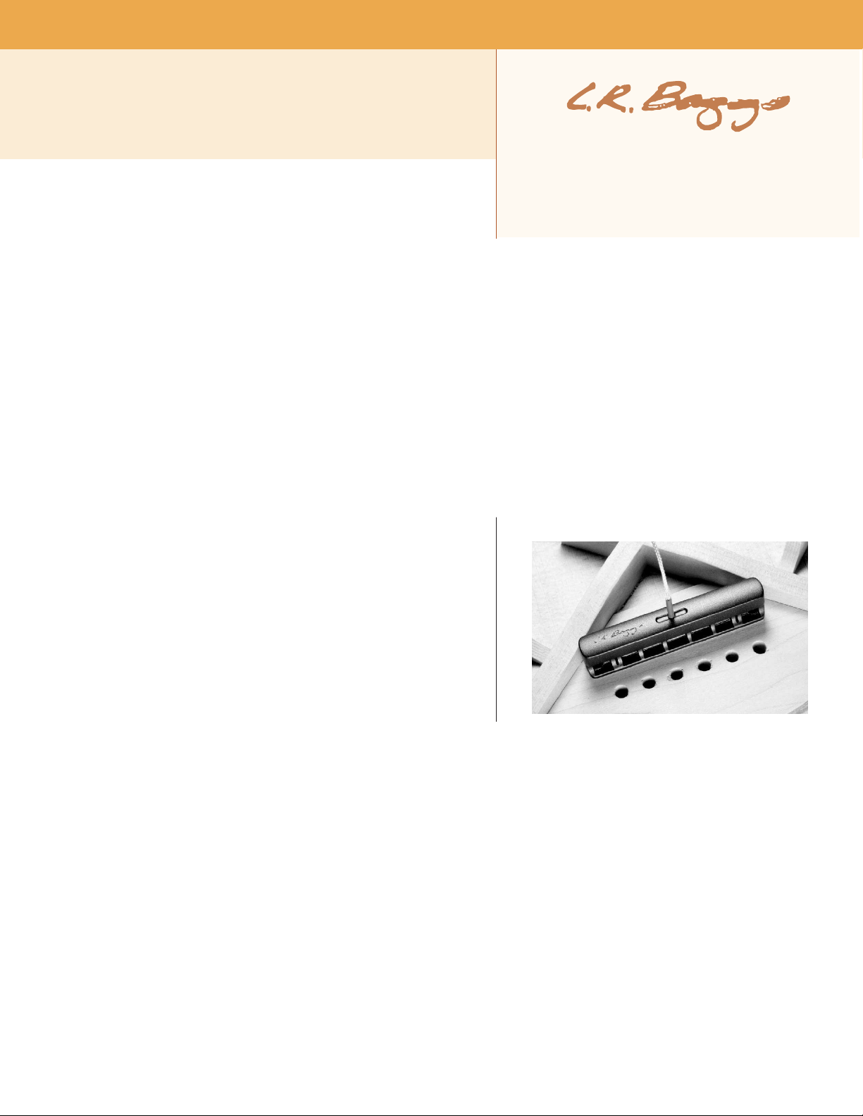
1 (one) iBeam br idge plate transdu cer
1 (one) iBeam mo unting fixtur e kit (not included with the iBeam Cla ssical)
1 (one) Element undersadd le tran sducer
1 (one) Remote Contro l II soun dhole controller
1 (one) flat cab le for Remote Control I I
1 (one) Batter y Bag
4 (four) self -stick wi re clip s
2 (two) extra iB eam adhes ive str ips
fig. 1
2.OVERVIEW AND CAUTIONS
The L.R. B aggs iMix is an onboard stereo mixer that combines the iBe am
br id ge pla te tra ns du ce r and the Element und ersaddle pic kup with an alldiscrete, class A, int ernal pre amp. The s ystem includes a soundhol e-mount ed
volum e/mix control (t he Remote Cont rol II) a nd our Ba ttery Bag.
We recommend that this s ystem be inst alled by a professional deal er/instal ler.
We do not provi de insta ll ation advi ce or sup po rt for home or hobb yi st
in sta lla ti ons . I nst all ers : p lea se re ad th e in str uct ion s car efu lly bef ore
proce eding. We wil l not be responsi ble for any damage to the guitar or per sona l inj ur y resul ting from inst allation, imp roper ins tallation , use or
misuse of the pr oduct.
The iBeam f its x-bra ced guitars with at lea st t hree inches of flat o pen space directly unde r the saddle (see fig ure 1). Ver ify that this r equirem ent is
met before m aking any alt eration s to th e guitar.
If the space is to o sm all to accomm odat e the i Beam, do not c ut t he i Beam to fit a tight er s pace.
The p reamp req uires a 9 volt bat tery, whi ch is not i ncluded in this package.
There is a sma ll slit u nder the iBeam cap abo ut 1/2" from each end of th e pickup. D o no t poke an ything into the sl it.
The pee l-and-sti ck adhesi ve is the bes t way t o adhere the iBeam. I t wi ll h old the iBe am quite firm ly, but w ill allow the pick up t o be safe ly remo ved
at a later tim e. Th e use of any adh esive o ther than the provided se lf-stick pads is n ot reco mmended a nd will void the warranty.
Avoid un necessary cre asing or ha rd bending of the El ement pic kup.
Install ation overview : The recom mend ed installat ion procedure is to begin by instal ling the strap jack and plugging it (along with the Remot e
Control II) into the corre ct prea mp sockets. Following that, the iB eam should be installed, connec ted and test ed to ensure optim um placement .
Then the Elem ent sho uld be instal led, c onnected and tested to ens ure pro per sound and str ing balan ce. The p reamp's g ain setti ng s hould the n be
adjuste d so that the iBeam's level m atches tha t of the E leme nt. Finall y, the preamp, Remo te Control I I and Bat tery Bag should be adher ed to t he
guitar and all w ires sh ould be sec ured with w ire clips.
Each pickup sh ould be instal led and tested as if it were the onl y source in the sys tem. Per fectin g the sou nd of each pi ckup ind ividually will
Page 2
provi de the most rewarding overall bl end whe n you final ly turn the mix kno b
to 12 :00 and hea r th e two s ources together.
3.STRAPJACK INSTALLATION
Drillin g the strapj ack hole: Fo r pro per installati on, this jack requi res a clea n
1/2" hole in the tail block of the instru ment. If the guitar lack s thi s hol e, start
by pla cing a piece of mas ki ng tape on the outside of the inst rument over the
drillin g area (to avoid chipp ing the finish), dril l a small pilot hole in the tail
block a nd then follow wit h a ste p drill.
Remov e the strap ring, retaining nut a nd one was her from the end of the jack.
Ther e sh ou ld still be o ne star l ock in g was he r, one flat was he r and a n ut
remai ning on the jack. Bring the jac k down through the so undhole into the
body a nd ins ert i t into the pre- drilled hole i n the t ail block. Usin g the internal
nut (be sure to include the flat and star was hers ), set the proper depth that
will allow the entire sma ller t hreaded sec tion to protru de f rom the instrume nt
(see fi gure 2) .
With the jack in pla ce, lay the remain ing washe r over the threa ds and atta ch
the external reta ining nut until it’s tight . Fin ish by attaching the strap ring (it
should cover the retai ning nut and washer). Asserting too much pressure may
crack the finish. Now brin g the preamp into the guitar (do not adhere it yet),
conne ct a battery, and plu g the strap jack cab le into the "output " socket. T hen
proce ed to the approp riate iBe am instal lati on instru ct ions in t he follow ing
sections.
4 . i B E A M I N S T A L L A T I O N : P I N B R I D G E
G U I T A R S
4.1 General posit ioni ng guide line s: The iBeam is a highly sens itive pickup;
th erefore, p lacement and the uni que character is ti cs of the ins trument are
critical fa ct or s in produci ng the outsta nd ing results of w hich the iBeam is
capable. A few mil limeter s in any di rection can have profou nd effe ct s on the
qu al ity of t he sou nd. Because ev ery g ui tar is d if ferent, we c an t el l you
approximatel y where t he pickup sho uld be placed, b ut we can not provide an
exact spe cificat ion.
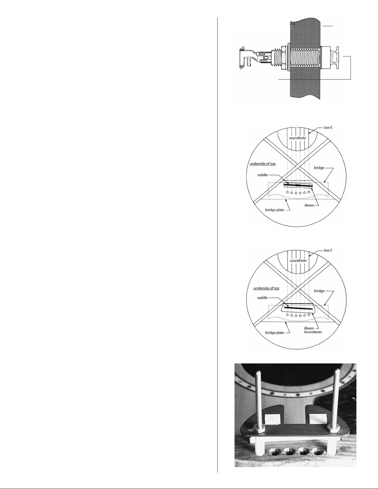
fig. 2
tail
block
smaller
threaded
section
protrudes
fig. 3: p ri ma ry location
The iBeam is desig ned to attach to the bri dge pla te direc tly und er the saddle
line and generally parallel to th e saddle, w it h the att ac hed peel-and-stick
adhesive. Good result s sho uld be con sistently had by attac hing the picku p as
sh ow n in figu re 3. How ever, bec ause ever y g uitar is u ni que, yo u m ay be
rewar ded by searchi ng for the optimum l ocation .
In genera l, placing the iB eam direct ly under the sa ddle wi ll pr ovide the
great est se nse of im mediacy, impact, snap and “strin g” sou nd. Offsetti ng the
pickup either toward the sound hole or towa rd the bridge pins in the area
sh ow n in f ig ure 4 wi ll incre as e the am ount of “ bo dy” in the sound and
general ly have a more mellow and hom ogeneous tone with less midrange. We
have ofte n achieve d our very best resul ts by placi ng the p ickup as close to the
string ball -ends as is pr ac tical and offse tting it about 1 to 2 mm toward the
trebl e si de of t he s addle.
An alternati ve location that has often worked well, prov ided the x-braces are
wide en ough, is to offset the pickup toward the front edge of t he bridge plate.
4.2 Pin bri dge install atio n (i nitial pla cement):
1. A ssemble the mounti ng fixture.
2. R emove the strings from th e pi n holes .
3. R each i nsid e th e hole and feel around und er the bridge to be sure the
bridge plate is fr ee from debris and o bstructio ns. If yo u are unsure, stick a
mirror inside to inspec t th is a rea.
4. Place th e statio nary rod of the moun ting fix ture in the high-E b ridge pi n
hole an d adjust the movab le rod la terally in the slo t until i t drops i nto the lowE bridge pin hole as shown in figure 5. Tig hten the nut to secure the mova ble
rod.
fig. 4: a lternative mounting area
fig. 5
5. Place the adhe sive dots on the fixture ove r the s addle (see f igure 5), o ne on
each side of the big s lot. R emove t he adhe sive backing f rom t he dots a nd
positio n the iBeam over the fixture in the desi red locati on. Stick the iBe am to
the adh esive d ots on th e fixture a s shown in figur e 6.
6. Remo ve the fixture and iBeam toge ther from the brid ge and remove the
adhesive backing from the b ottom sur face of the iBeam .
Page 3
7. Ins ert the fixtur e hold ing the iBeam int o the guitar. Find the hig h and low Estring brid ge pin ho les with the rod s on the fi xtur e.
8. Ins er t th e ro ds into t hese holes and then e levat e the fixture straight up until
the rods jus t poke out of the holes a bout 1/2". Gras p one o f the rods from the
outside of the g uitar and h old it. Do not pull up yet. Wh ile holdi ng the on e rod,
let go o f the fixture inside of t he g uita r and grab the other rod on the outs ide
of the guitar.
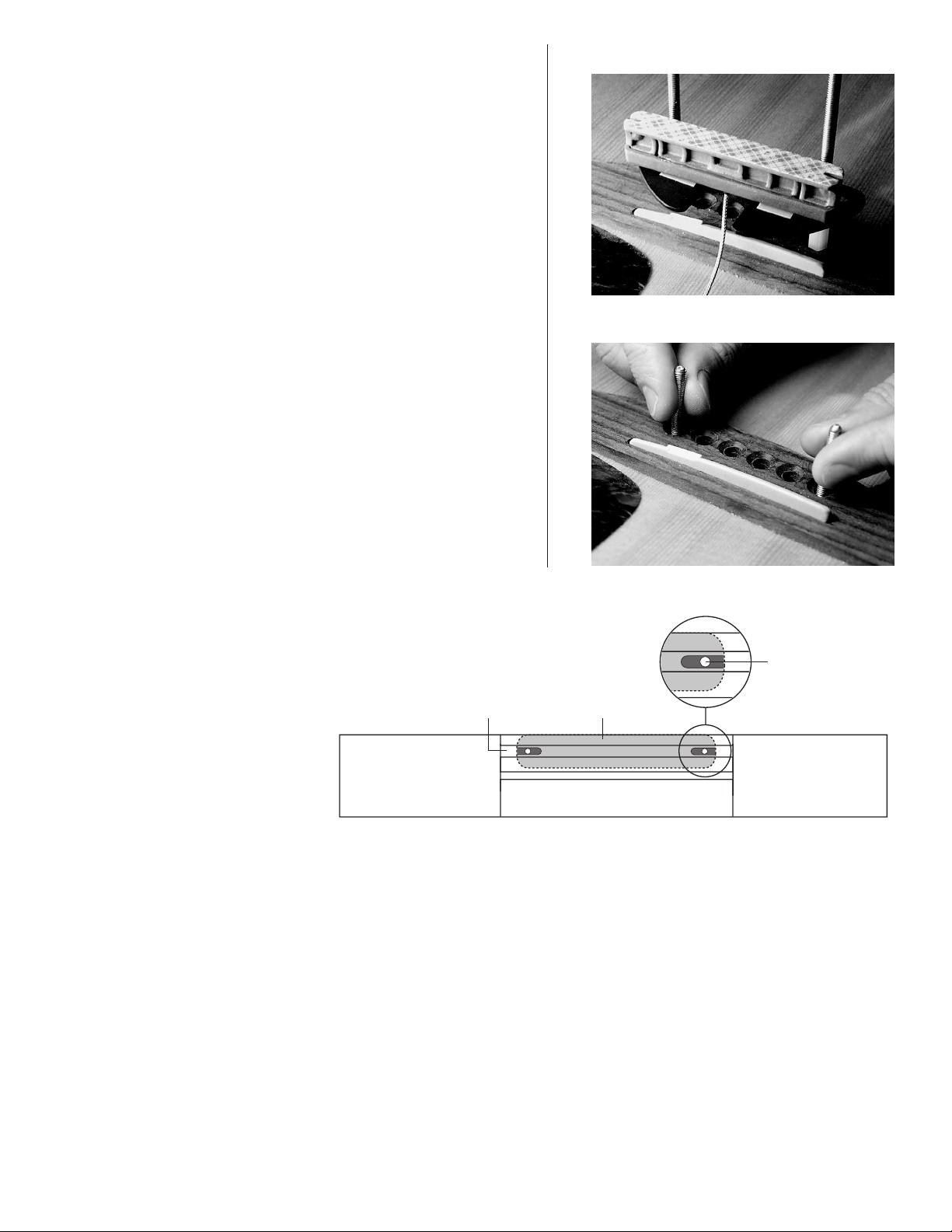
9. Now pull str aight up on the rods as sho wn in figure 7 to elevate the iBeam
until i t conta ct s the bri dge plate. Tug up on the rods to secure the pickup.
10. Pop t he fixture off the iBe am inside the guit ar and re move the fixture.
11. Press up firmly along the top surface of the iBeam, especia lly on the end s,
to secur e it. It’s a good idea to pre ss down on the bridge fro m the outsid e of
the guitar as you press up on the iBeam from the insi de to equalize pres sure
and a void cracking th e top. Wiggle t he iBeam fr ont to back a little as you
press .
12. Restring the guitar, c onnect t he iBe am to the p reamp's "iBeam" socket and
pl ug i nt o your amp or PA. Co nnect t he R em ote to the pre amp's "remo te "
so ck et, tur n the m ix wheel completely t o the iBea m, and test the p ickup
placement . I f the s ound i s satis factory (see b elow for a definition of this),
secure the wire with a wir e clip and turn to the E lement installa tion i n section
8. I f th e so un d is u nsati sf act or y, see s ec tio n 7. D o no t test the pi ck up
place ment without firm ly securin g the adhesive. Without complet ely securing
the pic kup, the so und test wi ll produce unrel iable results.
The opt im um l oc ation wil l delive r a sound tha t is fo cused an d ti ght, with
prope r s trin g balance and good pre sence. It will cap ture enough of the string
reson ance to be ar ticula te, b ut will be mellowed by a full and stron g body
re so nance. Ultima te ly, it will ac curatel y c apture t he d is tinct ton e of the
instrum ent. An uns atisfac tory location will often be charac teri zed by a woofy
or nasa l tone, poo r st ring bala nce and a h igh sen siti vity to feedback .
fig. 6
fig. 7
5.iBEAM INSTALLATION: NON-PIN
BRIDGE GUITARS
5.1 Genera l p osit ioni ng guid elin es: The
iB eam is a high ly s en sit ive pic ku p;
th ere fo re, pl ace me nt and th e u ni que
ch ara cteri sti cs o f th e in strum ent ar e
cr itic al fa ctor s in pr oduc ing t he
outstan ding r esults o f which the iBeam is
ca pab le. A fe w mi lli meters in a ny
di re ction can have pro found effec ts on
the quality of th e sound. Becaus e every
guitar is unique, you may be rewarded by
searc hing for the optimu m locat ion. With
non-pin bri dge guit ars, it is unlik ely that
the fir st selected spot w ill be ideal.
In g enera l, pl aci ng the iB eam dir ec tly
un der th e s add le w il l p rov ide th e
gr ea test sens e of im media cy, impac t,
sn ap an d “st ri ng” s ound. Of fs et ting th e
pi ck up either toward or away from the
sound h ole will increas e th e amoun t of “body” in the sound and genera lly have a more mellow an d homogen eous to ne with les s midrange.
5.2 Non -pin bri dge inst allatio n (i niti al p lacement) : Ins tall ation o n no n-pin bri dge guita rs requir es that you re move th e saddle, dri ll a small ho le
in each e nd o f the saddl e sl ot, and inse rt gui de pins to act as a reference when loca ting the iBea m. The hole l ocation s wi ll corres pond to the s mall
slots in the bott om of each end of the iBeam ( see figure 8). A good starting plac e is to drill the h oles so that the iBea m will b e centered under the
E strin gs. You will ne ed an inspe ctio n li ght, inspection mir ror, drill, 1 /16" dril l bit, matchs ticks or toothpick s, a nd a shor t penc il.
1. Drill a 1/16" hole throug h the bridge at both ends of the saddle slo t. If the guitar alread y has a h ole in the saddle slot for a pickup, you may be
able t o use this as one of t he holes. The min imum dis tance betwee n the holes should all ow the notches in each end of the iBeam's base to nes t
ove r th e protr uding matches or toothp icks that y ou will ins er t as a reference to place the iB eam.
fig. 8
Th is t op-d own vie w de pic ts t he b rid ge w ith
th e sa ddle re moved . The se p in h ole loc atio ns
ap ply to a ll non- pin bri dges .
saddle slot
bridge
drill pin hole here
iBeam
bridge
tie block
-9-
2. Pr ess t he matches or toothp icks into the holes until they just protr ude ( 1/16" to 1/8") into the guitar. The se wi ll ac t as locatin g p ins for
deter mini ng the iB eam's pla cement.
3. Remove the adhesive backing from the iBeam and, holding the iBeam betwee n you r thu mb and two middle finge rs, use your inde x and litt le
fingers to loc ate the matches.
4. Hol d the iBea m at a sligh t angle away from the insi de of the guit ar top, an d, u sing t he slot in one end of the botto m of the iBeam, locate one of
the protrud ing matches. Rot ate the othe r end of the pickup until you find the o ther protru ding mat ch w ith the other slot. Then ver y l ightly press
the adh esive a gainst th e bridge plate with just enou gh pres sure to hold it in place.
Page 4

5. Once you have tac ke d the pic kup into place, inse rt an inspection mir ror into the body to check the pla cement of the pickup. After confir ming
that it is l ocated correc tly, r emove the gui de pins and press firmly with a l ittle rocking motio n over t he sur face of the top of the pickup to secure
it to the bridge plate. Be sure to apply an equal dow nward force to the top of the bridge when press ing up f rom the inside to prevent damage to
the gui tar.
6. Restr ing the guitar, connec t the iBeam to the preamp's "iB eam" socket and plu g into your amp or PA. Connec t the Remo te to the preamp' s
"remo te" socket, turn the mix whe el compl etely to the iBe am, and te st the pick up placement. If the soun d is satisfac tory (see be low), sec ure the
wire with a wi re clip an d turn to t he Elem ent i nstalla tion in se ct ion 8. If the s ound is unsatisfa ctor y, see s ec tion 7. Do not test the pickup
place ment withou t firmly secu ring the adhesive. With out complet ely sec urin g the pic kup, the so und test wi ll produce unrel iable results.
The optimum locatio n will deliver a sound that is focused and tigh t, with p roper string balance and good presence. It will c apture enough of t he
string reso nance to be ar ticulate, but wil l be mellowed by a full and str ong body resona nce. U ltimate ly, it will accur ately captu re t he dis tinct tone
of the instrume nt. An unsatis factor y loc ation will often be character ized by a woofy or nasal tone, poor string balan ce and a high sensit ivity to
feedb ack.
6. iBEAM INSTALLATION: CLASSICAL GUITARS
6.1 General p osit ioning guidel ines : The iBeam is a high ly sen sitive pick up; t herefore, placement is a criti cal factor i n producing the outst anding
resul ts of w hich t he iBe am is capable. A few millimeters in any direction can have profound e ffects on the quality of the sound. In short, because
each guitar is different , we can tell you approx imately where the pic kup sho uld be placed, but we can not provi de an exact spec ification . Wit h
classic al guitar s, i t is unlikely that the first se lected sp ot will be idea l.
The classic al iBeam has a tunnel in t he center of the pickup designed to clear t he mid dle fan brace. The tunne l is wide eno ugh to allow for some
later al movement of the pick up.
We suggest tha t you ini tial ly positi on t he p ickup so it is laterally c entered over the b race an d th at t he entire p ickup is offset towa rds (and para llel
to) the tie block b y 2 to 5 mm. The i dea is to blend the d irec t stri ng sound with the s ound o f the body. T he more cen tered the pic kup is under the
saddle, the mor e string driv e and "snap" the soun d will h ave . Offset ting t he pickup towards the tie block or even towards the soun d ho le by a few
millime ters wil l all ow more bod y sound to mix with the string soun d. If you des ire more pres ence fro m the bass str ings and wish to mell ow out
the high strings, center the pickup under the bass strings and a ngle it so the center of the pickup' s high string end i s eith er i n fron t of or b ehind
the sad dle line by som e amount. Reversing this will res ult in mo re p resence for th e high stri ngs and les s for b ass. If yo u find th at the sm all E string
does no t have enough level, offset ting the pickup la terally towa rds it will increase its vo lume.
6.2 Classi cal installa tion (initi al placement): Most classic al gu itars are fan brac ed. The most common brac ing is t he Torres pattern with 5
longitu dinal braces. The iBe am is notched in the middle of the pickup to stra ddle the middle fan bra ce and will fit most Torres-pattern-bra ced
guitars. Classi cal bracing pat tern s vary, so before you proceed, check to ensu re tha t th ere is a total of 3" of clean , flat area betwee n th e two
brace s on both sides of the ce nter brac e under t he bridge (see fig ure 9).
Note: Do not trim t he edges of the pickup if you do not have sp ace betwe en the braces for the pickup. This will ruin th e pickup and void the
warra nty!
Install ation on clas sical guit ars r equires th at you re move the sadd le, dri ll a small hol e in each end of the saddl e slo t, and insert guide pin s
(matc hsticks or toothpic ks work well ) to act as a reference when placin g the iBeam. The hol e locat ions will corre spond to the small slots in the
botto m of eac h end of the iBea m (s ee f igure 8). A good star ting p lace is to dril l th e guide pin hol es s o that the iBea m wi ll b e cente red under the E
strings . You will ne ed an inspe ctio n li ght, inspection mir ror, drill, 1 /16" dril l bit, wooden matchsti cks or toot hpicks, and a sho rt pen cil.
1. Drill a 1/16" hole throug h the bridge at both ends of the saddle slo t. If the guitar alread y has a h ole in the saddle slot for a pickup, you may be
able t o use this as one of t he holes. The min imum dis tance betwee n the holes should all ow the notches in each end of the iBeam's base to nes t
ove r th e protr uding matches or toothp icks that y ou will ins er t as a reference to place the iB eam.
2. Press the matc hsticks or toot hpicks into the holes until they just protrud e (1 /16" to 1/8") into the guitar. These will act as locatin g pi ns for
deter mini ng the iB eam's pla cement.
3. Remove the adhesive backing fro m t he
iB ea m and, h ol di ng the i Be am bet ween
your t humb and two midd le finge rs, use
fig. 9
sound hole
your ind ex and lit tle fingers to loc ate the
match es.
4. Hold the iBeam at a slight angl e away
alternate placement
range (light gray area)
tie block
from the inside of the g uitar t op, and,
using the sl ot in one end of the bo ttom
of th e i Beam , l ocat e o ne o f the
protr uding matches. R otate the othe r end
of the pi ckup until you find th e oth er
pr ot rudin g m atch wit h t he slo t i n the
other end of the iBe am. Then very lig htly
pr es s th e adhesive ag ai nst the bridg e
plate wit h just enoug h pres sure to hold it
in plac e.
iBeam default position
5. Once yo u have tacked the pickup into
place, insert an inspectio n mirror int o the
bo dy t o ch eck the pl ace me nt o f th e
pickup. Afte r con firming that it is loca ted
saddle
(dark gray area)
co rr ect ly, re move t he gui de pin s an d
press firmly with a little rocking moti on
ove r the sur face of the top of the pickup
to se cure it to the bridg e plate. Be sure to
Page 5

apply a n equal d ownward forc e to th e top of the bridg e when pr essing up f rom the inside t o prevent dama ge to t he guitar.
6. Restr ing the guitar, connec t the iBeam to the preamp's "iB eam" socket and plu g into your amp or PA. Connec t the Remo te to the preamp' s
"remo te" socket, turn t he mix wh eel comple tely to the iBea m, and test th e pickup placeme nt. If the so und is satisfac tory ( see below for a
definit ion of this), secure the wire w ith a wire clip a nd turn to sectio n 8. However, wit h classical g uitars, it i s likely that t he r esults will b e less than
optimum at thi s position . If this is the cas e, we encourage you to e xper iment with alter native pla cements (see s ecti on 7). D o n ot tes t t he picku p
place ment withou t firmly secu ring the adhesive. With out complet ely sec urin g the pic kup, the so und test wi ll produce unrel iable results.
The optimum locatio n will deliver a sound that is focused and tigh t, with p roper string balance and good presence. It will c apture enough of t he
string reso nance to be ar ticulate, but wil l be mellowed by a full and str ong body resona nce. U ltimate ly, it will accurately captu re t he dis tinct tone
of the instrume nt. An unsatis factor y loc ation will often be character ized by a woofy or nasal tone, poor string balan ce and a high sensit ivity to
feedb ack.
7.iBEAM REMOVAL AND REPOSITIONING
The adh esive use d to secure the iBeam is ver y strong. Onc e you sti ck it down, it will inc rease its grip ove r about a wee k’s time. If you wis h to
experim ent with pla cement, it will be easier b efore the adhesive develops its full strength. To exp erim ent with pla cement, begi n by outlini ng the
pickup in its cur rent position w ith a pencil; this w ill act as a refe rence of the init ial location. Next, plac e three fingers a long the length o f the back
side o f the pic ku p. Pul l f irmly with even pressure towards the so undhole until the adh esive gives way. Rock it up onto o ne edge and then lif t up
one end to pul l the adhesive away from the bri dge pla te. D o not pull up on the cap. Becaus e the iBea m relies on a clean conn ec tion with the
guitar body, we do no t recomme nd re-using the adhe sive; instead, us e a new s tr ip.
To remove the adhes ive from t he bottom of the pickup, ro ll it off like car pet. After tacking the new pad to the bottom o f the pick up, use the edge
of a p enci l to pre ss t he adhes ive firmly to the pickup. Two extra pads are inclu ded in the kit, and extra pads are available in packs of 10 for $5.00.
Inspect t he bridge plate fo r any a dhesive residu e before you rep osition t he iBeam.
Now reposit ion an d test the pickup. Remember that movin g the pickup towards the saddl e will increas e presen ce and strin g respon se, while
movin g it away from the sad dle wil l incre ase warmth and bod y res pons e. If the sound is sati sfactory, secure the wire and continu e to the nex t
section. If not, continue reposi tioning the iBeam as needed until you find the
prope r lo cation.
8.ELEMENT INSTALLATION
8.1 Ins tall ation notes : For optimum per form ance of the Element, the bridge
slot must h ave a clean, flat surface free of any debris or over-spray from the
finish. The slot mu st be a minimu m of .125 ” (1 /8”) de ep, but we suggest a
depth o f at leas t .187" ( 3/16”) to avoid excessive saddle tilt .
The common ly-k nown 50/5 0 rul e app lies: The amoun t of saddle visib le above
th e br idge surface ( wi th pickup ins talled) s hould b e n o gr ea ter tha n the
am ou nt of sa ddle in the slot beneath the brid ge sur face; other wis e the
balance and ou tput of the pic kup may suffer.
8.2 Sho rt saddl e note : The firs t 1/ 8" of the Ele ment pick up i s no t ac tive. If you
do not h ave a m inimum of 1/4" of saddle b eyon d the E s trings, you may
experie nce low output on these strings . To reme dy t his, drill a small hori zontal
hole i n the end of the slot to exten d t he picku p f ur ther under the saddle (see
figure 10). To drill this hole withou t d isrupting the floor of the saddle slot,
place a small jeweler's sc rewd ri ver und er t he tip of the dri ll bit. On sho rt
saddles we also advise that the pickup exit hole be drilled into the end wall of
the saddle slot rathe r th an the slot's floo r (see figur e 12 ) to likewise extend
saddle/ pickup contact at the ex it end. Again use the jeweler's screwdriver to
prote ct the sadd le floor as you dril l.
8.3 In stallat ion: Remove the strin gs from the guitar. To dupli cate the strin g
he ig ht exac tl y, scri be a line a long th e fr on t edg e of th e sa ddle wher e it
ex tends ab ove the b ri dge. T he lin e w ill la te r be us ed a s a g uide w he n
removi ng materi al from the b ottom o f the sad dle to comp en sate for the
thickness of the pickup (.037” tota l). Remove th e sa ddle to d rill the ho le for the
pickup. Th e dr ill bit n eeds to be as larg e as the saddle sl ot will a llow.
Inspect the inside of the guitar and note the posit ion of the brace s an d th e
iBeam in relation to the saddle slot. Dri ll at either end of the slot on the side
that will enabl e you to avoid all bra ces as you pene trate the top, as shown in
figure 13. D o not drill throug h the iBeam! Blow out the slot with comp ressed
air and check for rem aini ng debr is.
fig. 10
fig. 11 fig. 12
dri ll b it
nor mal sadd le:
dri ll f loor
sho rt s addl e:
dri ll s ide wall
fig. 13
Th is view de pic ts the bri dge at an an gle th at is
le vel wi th th e gui tar t op an d perp end icul ar to
th e sad dle slot . Note the roun ded edge whe re
th e ho le h as been dri lle d.
bri dge
guitar top
brace
iBeam
extension
jew eler 's sc rewd rive r
dri ll b it
slo t
Important : Roun d the insid e of t he hole whe re it meets t he bottom of the slot
with a small, sharp knife or small f ile to avoid pinc hing the pick up a s the
saddle lies on i t.
Feed the p ickup i nto the s lot f ro m in si de the guitar w ith eit he r sid e up.
Inserting a toothp ick or si milar ob ject throu gh the ho le from the out side is
helpful in findi ng the lo cation of the hole on the i nside of the guita r.
Important : The fit of t he saddl e in the slot is the single most impor tant factor
in th is installa tion. I t is cru cial that the bo ttom of the sl ot and th e lower
proper saddle-pickup contact
(saddle lean exaggerated)
fig. 14
Page 6

surface of the saddle be flat to make even contac t with the pic kup. The sad dle sho uld fit
loosely eno ugh in the slot t hat it c an b e pulled out with your finge rtip s. It wil l then have a
fig. 15
sl ig ht for war d le an when t he string s are un de r te ns ion. I t is a bsolute ly necess ar y t o
compe nsate for thi s sli ght lean by sandin g a tilt in the bottom of the sad dle so it still sits
flat on the pickup when the s trin gs are at tension (see figure 14). If the saddle is t oo tig ht,
binds a t all or is too loo se, this will have a n egative effect o n the str ing bal ance an d
output.
Set the sad dle in the slot, noting how muc h m aterial must be removed to compensate for
the thickness of the pickup. Sand the bottom sur face of the saddl e on a belt san der until
the scribe line is just abo ve the bridge top. Fi nish sandin g the bott om by hand. It i s best to
do this against a machine d flat sur face with fine sand paper. Use a straightedge with a
stron g li ght sou rce to inspect the flatne ss o f your saddle.
Insert the pi ckup all the way into th e slot, place the saddle on to p of it, and tempor arily
secure it with a piece of tape. Se cure the wire wit h a wire cli p as clo se to the exit hole as is
practic al, wi th a one- t o two-in ch service loop. Fai lure to secu re the w ire m ay produce
bo om iness and fe edbac k. Now plug the Eleme nt into th e pre amp's "pic ku p" so cke t,
restr ing t he gu itar, plug in to your amp or PA and turn the mix knob co mpletel y to t he
Element . Confi rm that the EQ contr ols are at their defau lt positi ons and test the Element,
payin g careful attent ion to string ba lance. I f the s ound is sat isfactor y, proceed to the nex t se ctio n. If not, rea d on .
String bal ance p roblems are alm ost always the result of an une ven interface betwee n t he botto m of the sad dle and the sadd le slot. If the str ing
balance is une ven, che ck these surf aces to e nsure that they ar e both completel y fl at.
Tip: A segme nted packaging kni fe blade is a use ful too l in determini ng the flatnes s of the sad dle slo t. Bre ak off enough blade segments so as
much of the blad e fits into the slot as p ossi ble. Bri efly use a back-an d-forth scra ping motion to see if the slot botto m scrape s evenly. Any high or
low spots will be readily apparen t. A minor low spot in t he slot may be comp ensated for by shims under the p ickup; however, for gaps over .005"
or mult iple gaps, we reco mmen d rerou ting the slot.
9 . i B E A M G A I N C O N T R O L
The lik elih ood of the iB eam and E leme nt gain l evels being n aturall y equal is extr emely low. Therefore we have provided a ga in contro l that af fects
only the iBeam channe l, which is located on the upper righ t corn er of the pream p. Setti ng thi s is an esse ntial step in perfecting the mix. To a djus t
this co rrectly, you w ill need a smal l Phill ips screwdr iver.
Fir st, make sure every thing is plu gged i n and turned on, and r otate the mix whee l comp letely t o the Element. Now test the overa ll volume of the
Element by playing all the stri ngs in your norma l playin g style. Then r otate the cont rol co mple tely to the iBe am and do th e same. Note the
diffe rence b et ween th e two p icku ps.
Now adjust the g ai n control according ly. To i ncrease the g ai n, ro tate the s crew clockw is e; to dec rease the iBe am gain, rotate the screw
count erclock wise .
Once the gain has been adjus ted, again test both pickup s ind ividually, using the mix knob to pan betwee n the two. If the outpu ts differ, repe at
these s teps as necessary to mak e them eq ual.
10.FINISHING THE INSTALLATION
10.1 Preamp place ment: The pream p should be mou nted on th e back surface of the guita r, with the pre-set cont rols on the unit ac cessibl e
throu gh the sound hole (se e fi gure 15). Clea n all dust and oil from the area insid e the guitar where the pre amp will be mo unted, remove the
adhesive backing and press the unit into pl ace.
10.2 Remo te Control II place ment: Find a comfort able and convenien t place to affi x the Remote a t the edge of the sound hole -- most users will
find it be st to position the unit on the side of the sou ndhole that wi ll be above the strings when playing. Clean the desired placem ent area
compl etely, pe el off th e adhesive backing, an d stick o nce. See sectio n 11 .2 fo r us age det ails.
10.3 Batter y Bag placem ent: Stick the double -sided a dhesive to an easily access ible spot
inside of the gu itar near the prea mp. Insert the batte ry an d bat tery clip int o the bag. The
batte ry c an then b e changed by opening the flap on the b ag and pu lling out the batter y.
10.4 Securing w ires: Now secure all loo se w ires usi ng t he w ire clips provided. There
should be one for each pickup, along with clips for the Batte ry Bag and Remote Control I I.
Leave a small ser vice loop fo r eac h wire, but make sure they will not hit the insid e of the
guitar during on -stage movement (the pickups will sens e this contact).
11.USER'S GUIDE
11.1 Pream p controls: There are five co ntrols alo ng the rig ht ex teri or of the preamp:
iBeam ga in, iBe am low cut, iB eam mid c ut, Element mid cut an d stereo/mono. The gain
contr ol is covere d in sectio n 9. Set ting the rest of these cont rols properly is an ess ential
part of per fectin g your soun d. To set the se cont rols, you w ill need a small s crewdri ver.
iBeam low cut : This is a 12dB/octave low cut that adjus ts t he i Beam's low- end cuto ff f rom
60Hz to 640Hz. Make sure that the mix control is pan ned comp letely to the i Beam bef ore
testi ng.
iB eam mid cut : T his di al a dj usts t he i Beam' s m idran ge f re quenc ie s around 900 Hz.
Rotatin g th e control com pletely clo ck wise will give the iBeam full mid range outpu t and
essenti ally deactivate s thi s con trol. The counte rclo ck wise end re duces this par t of the
fig. 16
GAIN
iBEAM
PICKUP
OUTPUT
REMOTE
LOW
CUT
MID
MID
LO HI
60
-9dB
-9dB
MONO
STEREO
640
0dB
0dB
ON
Page 7

output by 9dB.
Element m id cut : T his control has th e same oper ation as th e iBeam mid c ut, but affects the Element. Be sure t o have the mix con trol pann ed
compl etely to the Element whe n testi ng this s etting.
Stere o/mo no: This determines wh ethe r the outpu t is summed to one mon o channel or spl it into two signals. Stereo mode requires the us e of a
standar d stereo cabl e or ste reo Y cable -- thi s mod e put s the Element on the tip chan nel and the iBeam on the ring chan nel. If you use a mono
cable in stereo mode, onl y the Elem ent will be present. This setting is useful for recordin g eac h pic kup independen tly, cre ating separa te blends
for two di ffere nt sets of s peakers ( for example, t he house spe aker s and stag e monitor s), or appl ying diff erent effects to ea ch chan nel. Th e
follo wing se ctio n de scribes h ow the Remo te Co ntrol I I op erate s in stereo and mono modes.
11.2 Usin g the Remote Control II: In mono mode, the volume whe el contro ls the levels of bot h chan nels e qually -- rotate the wheel towa rds the
neck to increas e the master volume. The mix control dete rmines the amount of each pickup in the ove rall blend. Ro tate the wheel complet ely
towards the neck fo r 100% iB eam, and c omplete ly towa rds the saddle for 100% Ele ment. The 12:0 0 po sition will give b oth picku ps equal output.
For most applic ations, an e qual blen d of both s ources should provide an effective balance bet ween the i Beam 's wa rmth, fidelit y and b ody
sensiti vity, and the Elem ent's presence and stability. For recording or intimate ven ues (es pecially when sol oing), favoring the iBea m may elicit a
warmer, richer, more natural ton e. Whe n p laying in lou d enviro nments or wit h an ensemble, favoring th e Element w ill provide mor e "cut," wh ich
will he lp bring the guitar through the mix.
In s tereo mode, each wheel becom es ass igned to a n indivi dual picku p and contro ls the outpu t of that s ource indepen dently. In this instance, the
"vol" wheel co ntrols the Eleme nt output and the "mix" whe el cont rols th e iB eam.
 Loading...