

L.R. BAGGS PREAMPS
CTRL-X
INSTALLATION MANUAL & USER'S GUIDE
483 N. FRONTAGE RD.
NIPOMO, CA 93444
1.PACKAGE CONTENTS
One (1) nine-pin output j ack
One (1) batter y clip with foam pad
One (1) cable ti e
One (1) 470 pf c apacito r
One (1) black sw itch bu tton
One (1) white switch butt on
Mountin g hardw are
2.OVERVIEW AND CAUTIONS
The followin g instruc tions are for a tradit iona l Strat with three knobs and a 5-way s witch. It is reco mmended that insta ller s perform a dry run
throu gh the entire proced ure before cutting or dril ling. We reco mmend that t his system b e instal led by a profess ional dealer/in staller. We do not
provi de install ation advice or suppor t for home or hobbyi st install ations. Installers : please rea d the inst ructions caref ully before proceedi ng. We
will no t be re spon sible for any damage to the gu itar or p ersonal inj ury re sulting f rom ins tall ation, use or mis use of th e produ ct.
3.INSTALLATION
WWW.LRBAGGS.COM
1. If you do not alrea dy have an X-Bridge in you r g uitar, install one accordi ng to t he installat ion instru ctio ns that com e with the bri dge. Remo ve
the middle tone pot and its wire to the 5-way switch (as stated in the instruction s), but do not insta ll the 5 meg vol ume pot or ster eo jack. Th e
only solder ing conn ecti on to make at this time is to put a jum per between the two lugs on the 5-way switc h that go to the tone pots, a lso stated
in the instruction s.
2. If you already have an X-B ridg e with passive w iring, unhook the conn ec tions fro m the 5 meg volume p ot and remove th e pot. Unsolder t he
wires that come from the output jack into the contro l cav it y; in a reg ular Strat there will be two. On the passive X-Br idge hook up there will be
three .
3. Uns crew the jack p late and remove the jack f rom the pla te. Unsolder the ground wire fro m the bridge (it usua lly goes from the volu me pot case
throu gh t he hole to the spr ing cavit y), so the p ickguard will co me comp letely off the guita r.
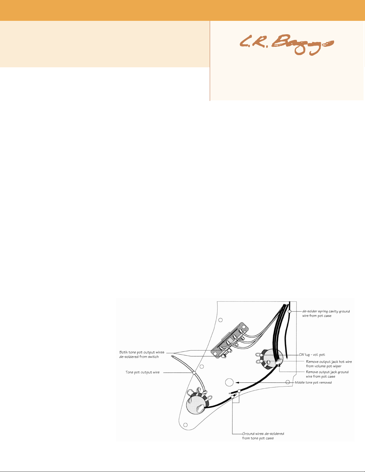
4. Com pletely rem ove the wire that runs from the 5-w ay switch to the CW (clockwis e) lug of th e Volume control. You sh ould also tempora rily
unsolde r one end of the wire that goes from the lower tone pot to the 5-way switch, to give your self more r oom to work . Figure 1 sho ws all the
wiring you will need to rem ove.
5. Now rep lace t he old output jack with the one that comes in the Ctrl-X kit. You will most likely need to do some woodwo rk ing in the jack cavi ty
to mak e room for the new jack (see fig ure 2), which is slightly larger than the orig inal jack. Use a Dremel r outer or chisel t o extend the inside of
th e cavi ty ( towar d th e br idge) by
about 1 /2". M ake sure th e large n ut
on the jac k bushi ng is tight, feed the
jack wires through the ho le into the
cont ro l cavit y, a nd re place t he ja ck
plate screws .
6. D rill a 1/ 4" hole in the pickgua rd
for t he t og gle sw itc h. The co rr ect
positio n fo r th is hol e is bet ween the
5- way sw itc h an d v olume kno b,
ce nt er ed on t he 5-way sw itch, a nd
volum e knob, center ed on the 5-way
sw itc h, about 5 /8" awa y from it ,
measure d from center to cente r (see
fi gu re 3) . Before y ou dr il l, hol d the
toggl e switch up to the inside of the
pickgua rd, 5/8" away from the 5-way,
to make sure the bodies of the two
sw it ches wi ll c le ar ea ch o th er. The
to gg le s witch sh oul d n ot b e a ny
fa rther t han 3 /4" a way fro m the 5way s lot, or it may hi t th e b atter y
when the whole thing is a ssemble d.
St ar t wi th a 1/ 16" pi lot ho le, and
rech ec k the loc at ion before dr illin g
the rea l hole.
fig. 1: s teps 1-4
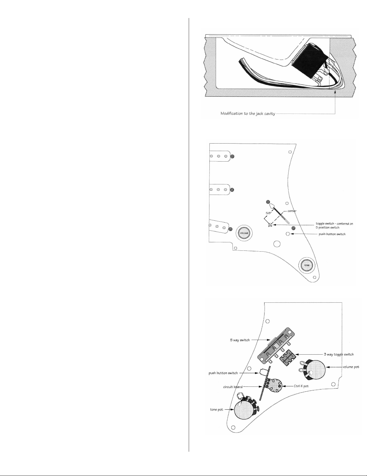
7. To posi tion the hole for the push -button swi tch, tem poraril y in -stall
the Ct rl-X pot and circuit board in the hole where the mid dle to ne
pot use d to be. Ce nter the po t in the hole, wi th the ci rcuit board par ts
facing the outs ide e dge o f the pick guard, as shown in figure 4. Be
sure that the edges of the circ uit board ar en't touchin g t he 5- way
switc h or the bottom of the tone pot. With the p ush-but ton switch in
the out pos ition, it wil l a lmost touch the p ickg uard. Trace around the
switch pl unge r, remove the Ct rl-X ass embly and drill a 1/16" pilo t
ho le where the cen te r o f the plu nger w il l b e. H ol d t he Ctr l-X
assembl y in place and make sure the switch can still be center ed on
th e pilot h ole. Then d rill the real hole. A 15 /64" bit is preferred;
however, you can use a 1/4" bit (althou gh this may look a bit large).
Gently de-b urr the out side of the hol e using a c ounters ink held in the
hand.
8. Now install t he Ctrl -X assem bly. The pot should g o d irec tly agains t
the pickguar d on the insi de, and the washe r and nut on the outsid e.
Fin ger tighten the asse mbly. Center the switch plun ger over its hol e,
and add the button (we'v e prov ided a choic e of white or bla ck). Then
tighten t he nut, m ak ing sure the butto n stays centered in its hole. On
some guitars, th e Ctrl-X circuit board will come cl ose to one lug of
the lower tone pot. I f it does, bend the lug a bit to make sure n othi ng
will sh or t ou t.
9. Figure 5 show s the wiring for the foll owing thre e s teps. S olde r the
black groun d wire fro m the circui t board to the volum e pot case. R un
the orange outp ut wire to the CW lu g of the vol ume pot, but don't
solder it yet.
10. In stall th e to ggle switc h. Remove th e de cora ti ve nut from t he
threa ded bush ing and adjust the remain ing nut and lo ck-wash er so
that the bushin g stic ks o ut o f the hole by about 2 or 3 thre ads; this is
enough for the deco rative nut to catch t he t hreads and tighten. If the
bushing sticks up to o far, the decorative nut will bot tom out before
the switc h is tight in its hole. Move th e inside nut out a bit an d try
again. Before you tighten the nut all the way, positi on the switc h on
the underside of t he pic kguard so the side with three wir es is closest
to the 5-way swit ch. This is neces sary so that e ach p osition on the
switc h (up, midd le a nd down) fun ctions the way it i s expl aine d in the
owner 's m anual.
fig. 2: s tep 5
fig. 3: o ut si de v ie w
11. S older the white wire fro m the toggl e switch to the 5-w ay switc h
output (the sa me lug from which you rem oved the ori ginal wi re to
the vol ume control). S olde r the ora nge wire from t he toggle s witch to
the CW lug of the volume co ntrol, along wit h th e or ange wire fro m
th e PC board. Both orange wires g o to th e sam e lug. Solde r the
groun d wire from the other two pot cas es to the Ctrl-X pot case. It
will be nece ssar y to first scrape some of the yello w fini sh fro m the
side of the pot for the solder t o stick to it.
12. Th e follow ing three steps are shown in figures 6 and 7. Now, wit h
the gui tar on its back, lay the p ickguard next to it, open- book fash ion,
and reso lder the main g round wire (from the spri ng cavity) to one of
the pot cases. You will need to solder three wire s to the circu it b oard.
The solder pa ds are locat ed in th e upper righ t h and corner of the
board away f rom the 5-way switch. First sold er the yellow wire from
the output jack to the lowest of the three pads (labele d Y ), then the
white w ire fro m the jac k to the ne xt one up (labeled W), and the XBridge coax to the top connections (wit h the box aroun d the m). See
figure 6. The b raid of the coax goe s to the lar gest hol e a nd the inne r
"hot" wire to the small one next to it. Be sure the sle eve ins ulator is
on the coax, and pull the braid through the circuit board hole as far
as i t wil l go be fo re s older ing i t. Cl ip an y long wi re en ds af ter
solderi ng, and mak e sur e the clipping s don't end up in the cavit y to
short thing s out later.
13 . Aft er y ou 've completed t he solder in g, bu ndle th e three wires
toget her with the cable tie provided in the kit. T ighten the cable tie
aroun d the three wir es about one in ch away from the circuit boar d.
This ensures that the insulat ion f or th e X-Bri dge coax will not s lip
back and expose the bare brai d, and helps to keep the wires under
contr ol. Cau tion : finger tighte n only. Us ing pli ers to tig hten the
cable may cut th e insulati on, causing a sh ort. Clip off the excess
cable t ie (see f igure 6 ).
fig. 4:
inside view
14. So lder the bl ack wi re from the output j ack to the vo lume pot
grou nd, and the red wire from t he jack to the volu me pot wiper
(middle ) lug. R esolder the wir e from the lower tone pot to the 5-wa y
sw it ch . I f there is en ough le ngth, ru n it be hi nd th e Ctrl-X ci rcuit

fig. 5:
steps 9, 10 & 11
fig. 6: steps 12, 13 & 14
wi re tieco ax wir e s lee ve insulator
X- Bri dge br aid ed wir e
X- Bri dge
ho t w ire
wi re wir e t ie
board so it will not be in the way of the little trim pot and swi tch that are
on the board; you will be adjus ting thes e soon.
15. To insta ll t he batter y clip in the cavi ty, first make sure the surface of the
fr om out put ja ck
ye llo w w ire tie
fr om out put ja ck
cavit y is cle an of oil, dust or solder flux. T hen place the batter y in the clip,
remove the back ing from the adhesi ve pad and press them down into the
cavit y with the bat tery conn ecto rs facing away from the brid ge, as shown
ph ase sw itc h
in figu re 8. Attach the battery sna p; the w ires comi ng o ff the ba ttery shoul d
exit up ward.
vo lum e l eve l
tr im pot
16. Fo ld the w ire harnesses into th e ca vi ty as you close the pickg ua rd
assembl y like the cover of a book . You may need to open it and close it a
few t imes to tuc k the w ires into their plac es.
pu sh- but ton
sw itc h p lun ger
17 . At this time, screw the pic kg uard do wn wi th on ly a coupl e of the
screw s, le aving all of the screws surrou ndin g the control cavity off. There is
a ph ase sw itch and a level con trol on the circuit board that you need to
acces s by lifting up the lower corner of the pickgua rd before the job is complete. If this is a ne w X- Bridge instal lation, go bac k to the X-Bridg e
install ation ins tructions and finish set ting up your bri dge, then com e back to this m anual for the fi nal adjustm ent of the Ctrl-X.
4 . F I N A L A D J U S T M E N T S
Lift up the pic kgua rd unt il you can see the Ctr l-X circuit board, as show n in figu re 9. In the upper left corner o f the boa rd the re is a small trim pot.
Make s ure the white arrow is set to about the 2:00 position (a small Philli ps s crewdrive r work s well ). Set the push-button swi tch to t he " in" positi on
(mono mode) , a nd the toggle switch to t he m iddle (mix) posit ion. Plug into an amp using a regular guit ar cor d. Turn the volu me pot and lower t one
pot to 10 and pla y. Tur n the mix pot (middl e pot) f rom 1 to 10 while pla ying. You should hear the mag neti c pickups when the mix is on 1, an d the XBridge when it is o n 10, If you hea r a dro p in volume in the middle of the mix pot' s range, the X-Br idge and magneti c pickup s are o ut of phase. Lift
the pic kgua rd and fl ip the litt le p hase swit ch. You may wis h to flip this switch a couple of tim es t o make sure you have it in the best position . Fi nally,
adjust the X-Br idge volume with the trim p ot on the circu it board. With this adju stment yo u can make the overall out put level o f the X-Bridg e either
quieter, lou der, or the same as the m agnetic p ickups. Set it to your liking, repl ace the res t of th e pi ckguard screws, and you're done!
(see following page for more figures and user's guide)

fig. 7
fig. 9:
final adjustments
fig. 8: step 15
5 . U S E R ' S G U I D E
Advantages of Ctrl -X:
- Magne tic pickups remain p assi ve at all time s. Even whe n mixed with the active X -Bridge s igna l, your stock magnetic s are u ncha nged.
- Onb oard mass ive mixing : A stere o Y-ca ble and two amps are no longer nece ssary in ord er to mix the magneti c and X-Br idge pickups toge ther.
Simply use the " pan" pot in mono m ode to de termine how much o f each si gnal is i n the mix .
- Two guita rs in on e: A stereo mo de is availabl e at the pu sh of a but ton for sonic adventure rs. Send your X-Bridge and magnet ic signal s to two
diffe rent channe ls or amps for the ultimate in c ontrol and sound shaping possib ilities (fo r instan ce, ad d distor tion to your magneti cs w hile k eeping
the X-B ridge sig nal clean f or a mo re acoust ic s ound).

- Onboard pha se con trol: The phas e
relat ionship o f th e X-Bridge an d th e
ma gne ti c p ick up s i s a n i mpo rtant
fa ctor in the qual ity of th e m ix ed
sound. Un der your pi ckgu ard on th e
Ct rl -X circuit board is a t iny swi tc h
th at c ontro ls t he p ha se of the XBridge pi ckup. T his should have been
set by the profe ssional who in stalled
yo ur Ct rl-X , bu t fe el fr ee to
experim ent.
- Ctr l- X p rovid es an al l-d isc rete,
cl ass A prea mp f or t he X -Br idge
si gnal : Feel free to send t his
noisele ss, user -friendly signal direc tly
to a PA or amp witho ut l osing the rich
tonal qua lities of t he X-Brid ge.
Mono an d st ereo modes:
There ar e t wo ways to use Ctrl -X, by
selecting mono or ste reo mode. Th is
fu nct io n is c ontro ll ed by the new
pu sh -button sw itch loc at ed ne xt t o
the five-way switch on the face o f the
guitar. When the button is pushed in,
mo no mod e is act ivated; w hen the
butto n i s out, you a re in ste reo mode .
The five- way swit ch i s not a ffected by the C tr l-X in any way ; it wil l cont inue to func tion with the m agnetic pickups as it always has. It will also have
no effect when you are using the X-Bridge alone.
Mono mode : Use thi s mode when you just wan t to plug in and go. Use a st anda rd 1/4" gui tar cable wit h the push- button switch i n the "in" posi tion.
The n ew t hree-po sition to ggle switch dete rmines wh ether you hear m agnetics on ly, a ble nd o f magne tics and X- Brid ge, or the X- Bridge on ly.
With the tog gle sw itch in the "ma gnetics only" position (up and towards the nec k), the vol ume knob functions as usual, but all magne tic tone
functions are combined on the bottom tone knob. Th e center k nob will have no functio n with the toggl e swit ch i n this positio n. W ith the exception
of this center k nob, your guitar s hould sou nd and fu nc tion as i t alway s has ( before th e X-Bridg e was insta lled).
With the toggle swi tch in the down pos ition, the magnetics are shut off and the volum e knob now controls the X-Brid ge volu me. The two "tone"
kn obs have no func tion . You will he ar only the X-B ridge wit h the tog gle swi tch in the "down" posi tion.
With the to ggle swit ch in the cen ter posit ion, you can mix the X-Br idge with the passi ve magnet ic pickups. The volu me knob becom es a master
volum e and will now control the outp ut of the blend. The cen ter tone knob becomes a "pan" or mix pot. R otating this knob comple tely clockwise
will isolate the ac tive X-Bridg e pickup; rotat ing t he knob complete ly counterclockwis e will isolate the passive magnetic s. Use this control to
deter mine the ra tio of X- Br idge to magnetic s in the overa ll sound. The bottom tone knob con trols t he tone for the ma gnetic pi ckups onl y.
Stere o mod e: In ste reo mode, with the push-bu tton in the "out" posit ion, the magn etics and X-Bridge signa ls are com pletely sepa rated from each
other. You'll need to use a stereo Y-cable to access them. Th e magnetic pick up sig nal is on the tip cha nnel of the ste reo jack, an d the X-Bridg e si gnal
is on the ring chann el. The X-B ridge signal from Ctr l-X is act ive and can be sent directly to a PA with out los ing the low s and richnes s the X-Bridg e
provi des. You can send the two signa ls to s eparate amp chan nels, volum e pe dals, effec ts, EQs or even t wo differ ent amp s. This s etup will give y ou the
most co ntrol a nd flex ibil ity to cu stomize your s ound. We recommen d that you do not plug both signals into a single ch annel of a combo a mp.
If you happen to bump the push-bu tton switch whi le pla ying in stereo mode (accide ntally switch ing the guitar to mono mode) , y ou m ay be in for a
surpris e, dep endi ng on whe re the controls are set . Rememb er, the contro ls are differe nt in m ono and ste reo mod es.
With the togg le switch in the up or "mag netics only" positi on, the volu me k nob contr ols the vol ume and the lower tone knob con trols the magne tic
tone. The center knob h as no fun ct ion.
With t he toggle s witch in the down or "X-B ridg e" posit ion, the center knob beco mes the v olume control for the X-Bri dge and the othe r two knobs
have no func tion .
With the toggle swi tch in t he c enter posit ion, the volum e pot cont rols t he m agnetic pickup volu me, the cent er k nob become s the X-Bridge volume,
and the lower tone knob contro ls t he tone for th e magneti cs.
As yo u may h ave n oticed, the re is n o EQ control for the X-Bridge ; any EQ you want to add shou ld be don e outboar d of the guitar.
Phase:
If you intend to play using only the X-Bridge or the magn etics at any given time, the phase relatio nship between the two is not impor tant. When
playi ng in Mono mode, wher e the two signals are mixed togeth er o n the guitar, ph ase may have a b ig effec t in the quality of t he mixed sound. The
optimum phase for the X-Bridg e may be readily confirmed by experime nting wit h the two pos itions of the tiny s lide switch on the Ctr l-X circu it
board und er your pickguar d.
To change the phase of th e X-Bridge, simply remove th e pi ckgu ard screws around the contr ol cavity and li fe the pic kguard up enough to have
acces s to the Ctr l-X circ uit board. You' ll s ee the tiny s lide s witch next to where t he batter y snap is soldered. This is the phase switch. In stereo mode,
when using two separ ate amps there shoul d be no phase conf lict s, but be sure to place the speak ers as far apart as the Y-ca ble will allow for the
best pe rfor mance. However, if yo u plan to send the two si gnal s into two cha nnels of the same amp, please read on.
The onl y outboar d phase c onflict you may face is when you are p laying in s tereo mode using two channels o f the sam e amp. Surpri sing ly, the re is no
set s tandard for ph ase rel ationship between adjacen t channel s in th e same am p. In t his situa tion th e magneti c and X -Bridge signals may be
compe ting with e ach other for the sa me speake rs. If t he t wo chan nels are out of phas e with each other, this m ay result in a weak blend ed sound. If

this ha ppens you will n eed to chan ge the ph ase of th e X-Bridg e when play ing wit h th is setu p.
Now, if you find yours elf us ing different outboa rd equ ipment and yo u prefer th e on e amp/two cha nnel s setup, the phase re lationship wi ll lik ely
becom e "chop s uey" and yo u'll prob ably n ever be able to d etec t phase confl ic ts. Ho wever, if you do wan t phase con trol each tim e yo u play thro ugh
a different amp, swi tching phase o n the guitar will become a chor e. In t hese i nstance s, we hig hly reco mmen d our Para D.I. outboa rd preamp, w hich
has a r eadily accessible phase swi tch and f ive-ban d EQ.
Ground loops: If you are using two amps and hear a hum, chances are you have a ground loop. These should be handled by using standard studio
groun d lo op elim ination tec hniques.
Trim pot: Next to the phase switch on the Ctrl-X circuit board is a trim pot. You can use this to control the output level of the magnetics. This should
be a co ntrol t hat onl y ne eds to be set on ce, but fee l free to expe rime nt. A small screwdriver wor ks well for adjust ing this.
Battery: Ctrl-X should provide approximately 1000 hours of play time per nine-volt battery. When you start to hear unwanted amounts of distortion
on the X-Bridge sig nal during hard strum ming, replace the batte ry. Even if the battery is totall y dead, the stoc k guit ar is always avai lable by flippi ng
the th ree-way switch to "magne tics onl y." To cha nge the bat tery, si mply remove the p ickguar d screws to gai n access to the contr ol cav ity a nd
repla ce the sin gle 9V with a new none. Be sure the new batter y is secur ed in its clip and will not ratt le around once the pick guard is replaced. TO
conse rve battery life, u nplug the guitar w hen it is not in u se. Remember, if the guitar i s plugged in, C trl- X is on w hether you're pl aying i t or not.
 Loading...