LR Baggs Anthem SL Installation Manual

ANTHEM-SLTM
TRU•MIC TECHNOLOGY
I N S T A L L A T I O N M A N U A L

1.PACKAGE CONTENTS
One Anthem-SL withTru • Mic, Element pickup, endpin preamp, volume control and battery lead __ pre-assembeled One battery bag
Six self-stick wire clips
Two adhesive pads for volume control One extra adhesive set forTru • Mic
2. OVERVIEW AND CAUTIONS
The Anthem-SL features our patent pending Tru • Mic microphone technology. The mic is designed to capture the majority of your guitar’s true voice in a way that only a microphone is capable of - plus it is amazingly feedback resistant. Our Element under saddle pickup carries only the lowest frequencies for punch and authority.TheTru • Mic and Element pickup are preset for optimum performance and the soundhole mounted controller has volume and mic gain trim controls.
This system must be installed by a professional dealer/installer.We do not provide installation advice or support for home or hobbyist installations. Installers: please readtheinstructionscarefullybeforeproceeding.Wewillnotberesponsibleforanydamagetotheguitar,pickupsystemorpersonalinjuryresultingfrominstallation.
3. STRAPJACK INSTALLATION |
|
|
|
Drilling the strapjack hole |
|
|
|
For proper installation, this jack requires a clean 1/2”hole in the tail block of the |
|
|
|
instrument.Iftheguitarlacksthishole,startbyplacingapieceofmaskingtapeon |
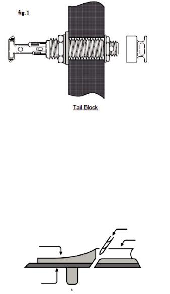
fig. 1 |
|
|
|
|
|
|
the outside of the instrument over the drilling area (to avoid chipping the finish), |
|
|
|
|
|
|
|
drill a small pilot hole in the tail block and then follow with a step drill bit. |
|
|
|
Installing the strapjack |
|
|
|
Remove the strap ring, retaining nut and one washer from the smaller threaded |
|
|
|
section of the jack. There should still be one star locking washer, one flat washer |
|
|
|
andanutremainingonthelargerthreadedsectionofthejack.Bringthejackdown |
|
|
|
through the soundhole into the body and insert it into the pre-drilled hole in the |
|
|
|
tail block. Using the internal nut (be sure to include the flat and star washers), set |
|
|
|
the proper depth that will allow the entire smaller threaded section to protrude |
|
|
|
fromtheinstrument(see figure 1).Withthejackinplace,laytheremainingwasher |
|
|
|
over the threads and attach the external retaining nut until it’s tight. Finish by |
|
|
|
attaching the strap ring (it should cover the retaining nut and washer). Asserting |
|
|
|
|
|
Tail Block |
|
too much pressure may crack the finish. |
|
|
|
|
|
|
|
|
|
|
|
4. ELEMENT PICKUP INSTALLATION
For optimum performance
Thebridgeslotmusthaveaclean,flatsurfacefreeofdebrisandexcessover-sprayfromlacquer,(sometimesleftfromguitarmanufacturers).Stringbalanceproblems are often the result of an uneven interface between the bottom of the saddle and the saddle slot floor. Both surfaces must be completely flat to give you the best chance at a successful installation.
The depth of the saddle slot is an important factor. A tip to help determine if your slot depth is adequate is the 50/50 rule which basically says:The amount of saddle visible above the bridge surface (with pickup installed) should be equal to or less thantheamountofsaddleintheslotbeneaththebridgesurface.Aninstallationin which you have a tall saddle in a very shallow slot could be the cause of problems ranging from string to string imbalance, excess feedback, and poor tone quality.
Drilling the hole
Useadrillbitwithadiameterthatislargeenoughforthepickuptofitthroughbut no larger than the width of the slot, usually between 3/32” and 1/8”. Just before you begin, inspect the inside of the guitar and note the position of the braces in relation to the saddle slot. Drill the hole in the extreme end of the slot at a slight anglebeingcarefultoavoidallbracesasthedrillbitpenetratesthetop(see figure 2).Usinganexactobladeorasmalljeweler’sscrewdriver,roundoffthesharpedge of the hole where the pickup bends to protect the pickup from being kinked or pinched. Clean all loose debris from the slot.
fig. 2
This view depicts the bridge at an angle that is level with the guitar top and perpendicular to the saddle slot. Note the rounded edge where the hole has been drilled.
drill bit
slot
bridge
guitar top
 Loading...