

Page 1
L.R. BAGGS PICKUPS
ELEMENT ACTIVE SYSTEM
INSTALLATION MANUAL & USER'S GUIDE
483 N. FRONTAGE RD.
NIPOMO, CA 93444
WWW.LRBAGGS.COM
TABLE OF CONTENTS
1. Package contents
2. O verview and cautions
3. S trapjack/preamp installation
4. P ic ku p In st al la ti on
5. Finishing the installation
6. O ther app li cations
1.PACKAGE CONTENTS
One (1) Element Active Sy st em w it h un de rs ad dl e pi ck up, en dp in p re am p an d volume control pre-attached
One (1) Battery Ba g
Three (3) self-stick wire cli ps
2.OVERVIEW AND CAUTIONS
The E lement Active System combines El ement undersaddle pickup with a pre-contou red, all-discrete c la ss A endpin p re am p. A soundholemounted volume contro l gives you add itio na l con trol and ver satility with out having to dri ll any hol es in your instrument . The Element Active is
designed t o interface with j us t about a nything you plug into, but best results will be a chie ved with a high -q ua li ty, full-range P.A. Plu ggin g in an d
unplugging the cord will turn the preamp on and off.
We recommend tha t this system be installed by a profes si on al dealer/installer. We do no t provide ins ta ll at io n advice or supp or t for home or
hobbyist installations. Installers: please read the inst ru ct ions caref ully befor e proceeding. We will not be respo ns ib le for any damage to th e guit ar
or personal injury r es ul ti ng f rom installa-tion, improper installation, use or misuse of the produc t.
3.STRAPJACK/PREAMP INSTALLATION
Drilling the stra pjac k h ole: For prop er in st al lation, this jack requires a clea n
1/2" hole in the tail block of the instrument . If th e guitar lacks this hole, s ta rt
by placing a piece of masking tape on the outside of t he instrument ove r the
drilling area (to avoid chipping the finish), drill a small pilot hol e in the tail
block and then follow wit h a step dri ll .
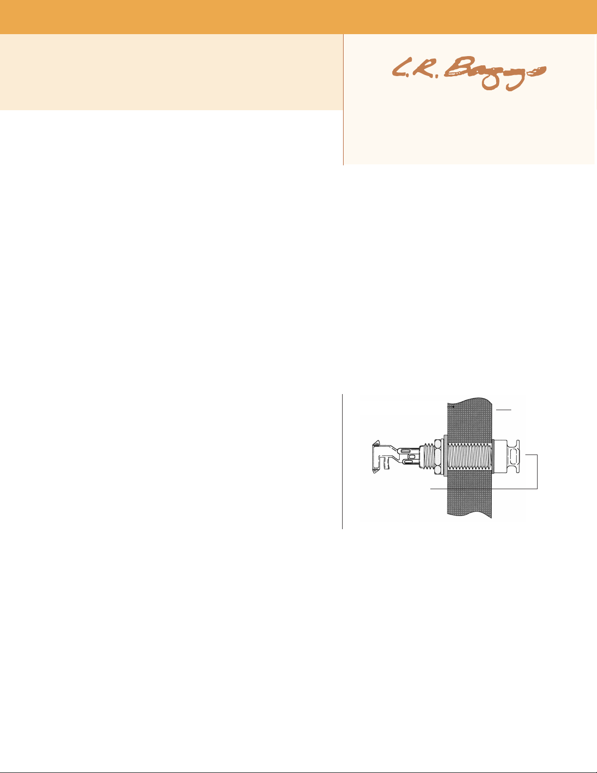
In stall ing the strap jack: Re move th e st rap rin g, r etain ing nut and o ne
washer from th e end of the jack. There should s till be one s ta r lock ing wash er,
one fl at washer and a nut remaining on the ja ck . B ri ng the jack down through
the soundhole in to the bod y and inser t it int o the pre- dril le d hol e in the tail
block. Using th e inte rn al nut (b e sure to include the flat a nd star washers), set
th e pr op er d epth th at will al low th e en tire s malle r th re aded se cti on t o
protrude from the instrument (see f ig ure 1).
With the jack in place, lay the rem aini ng wash er over the th reads and attach
the external reta in in g nut until it’s tight. Finish by att achi ng th e strap ring (it
should c over t he retaining nut and washer). Asserting t oo much p re ss ure may
crack the finish. Now brin g the pre am p into th e guitar (do not adhere it yet) , conn ec t a batte ry, and plu g the strap jack cable into the "o ut pu t"
socket. Then proc ee d to following section.
fig. 1
tail
block
smaller
threaded
section
protrudes
4 . P I C K U P I N S T A L L A T I O N
Installation notes: For o pt im um perfor ma nce of the Element, the br idge slot must have a clean, flat sur face fre e of any de br is or over-spray from
the finish. The s lo t mu st b e a minimum of .125” ( 1/ 8” ) de ep, bu t we suggest a depth of at least .187" (3/16”) to avo id e xcessive saddle tilt.
The commonly-known 50/50 rule ap pl ie s: The a mo un t of saddle visible above the brid ge s urface (with pickup i ns ta ll ed ) sh ou ld b e no gre ater than
the amount of saddle in the slot beneath the bridge surf ac e; otherwise the balance and ou tp ut o f th e pi ck up m ay suffer.
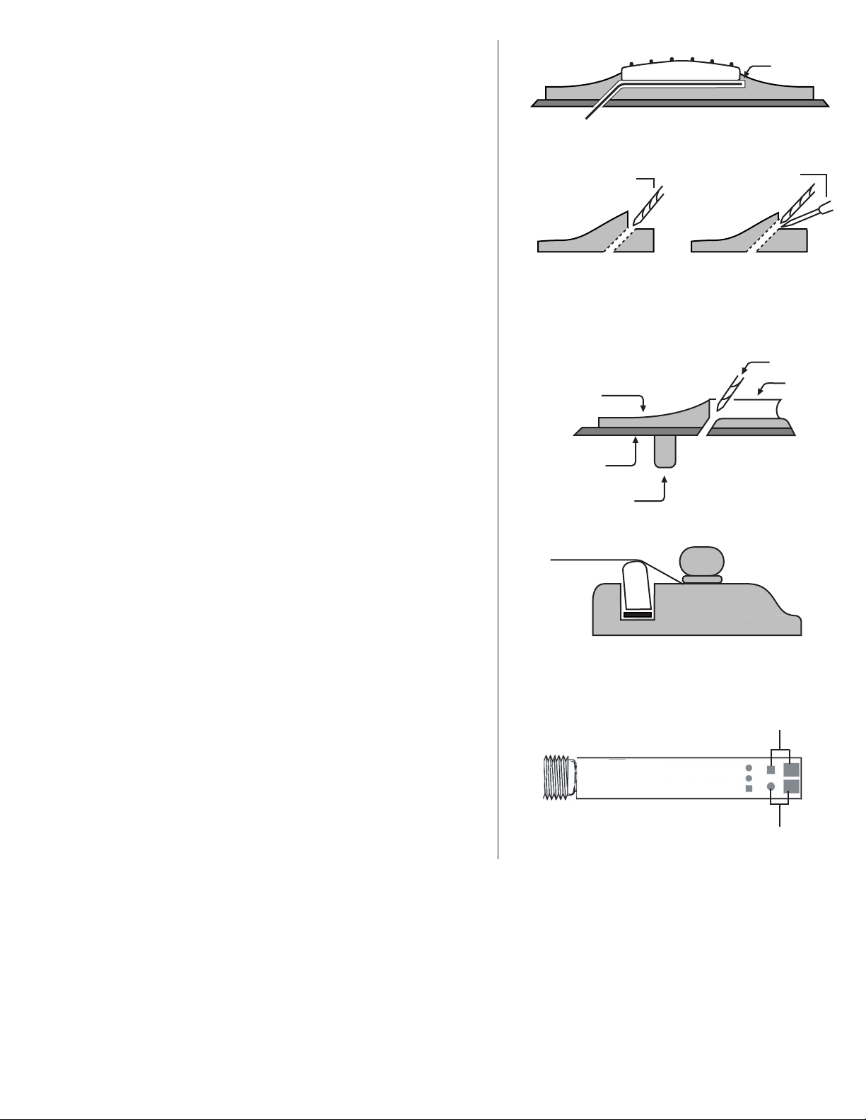
8.2 Short saddle note: The first 1/8" of the Element pickup is not active. If you do not have a minimum of 1/4" of saddle beyond the hi-E string, you
may experience low output on this string. To remedy this, drill a small horizontal hole in the end of the slot to extend the pickup further under
the saddle (see fi gu re 2). To drill this ho le wi th ou t disrupting the floor of th e saddle slot, pl ac e a small jewe ler' s screwdriver u nder th e tip of the
drill bit. On shor t sad dl es we also advi se that th e pic ku p e xi t hol e be dri lled into th e end wall of the sad dl e slo t rather than the sl ot 's floo r (se e
figure 3) to likewise extend saddle/pickup contact at the exit end. Again use the jeweler's screw dr iver to protect the saddle floor as you drill.
8.3 Inst al lation: Remov e the strings from th e guitar. To duplicate the stri ng height exact ly, scri be a line along the fr ont edge of t he saddle where
it extends above the bridge. The line will later be used as a guide when remov in g material from the bottom of th e saddle to co mp en sate for the
thickn es s of the pic kup (.037” total). Re move the saddle to drill the hole for the pickup. T he drill bi t needs to be as la rge as the saddle slot will
allow.
Page 2
Inspect th e inside of the guitar and not e the position of the braces and the
iBeam in relat ion to the saddle slot. Dr ill at either end of th e slot on the si de
that wi ll enable you to avoid all braces as you penetrate the top, as show n in
figure 5. Bl ow out the slot with compressed air and check for remaining debris.
Import ant: R ou nd the inside of the hole w he re i t meet s the bo tt om o f th e slot
with a small, sharp k ni fe or sm all file to avoi d pi nc hi ng t he p ic ku p as t he
saddle lies on it.
Feed t he picku p int o the slot from in side the guit ar wi th eithe r sid e up.
Insert in g a toothpick or similar obj ec t through the hole from th e outside is
helpful in finding the location of the hole on the inside of the guitar.
Import ant: The f it of t he saddle i n the s lo t is the single most important factor
in this installation. I t is crucial that the bo ttom of th e sl ot a nd t he lower
surf ace of the sadd le be f lat to make even contact with t he pickup. The sa dd le
sh ou ld fi t loo sely enoug h in the s lo t tha t it can b e pulle d out w ith you r
finger ti ps. It wi ll the n ha ve a sli ght forward lean when the strings are under
te ns ion . It is abs olute ly n ecess ary to comp ensat e fo r th is s lig ht lea n by
sanding a ti lt i n the bottom o f the sadd le s o it still sits flat on the p ic ku p wh en
the stri ng s are at ten sion (see figure 6). If th e sadd le is too tight, binds at al l or
is too loose, this will have a negati ve effect on the string balance and output.
Set the sa dd le in th e sl ot, noting how much mate rial m us t be removed to
compensate for the thi ck ness of the pickup. Sa nd the bottom sur face of the
saddle o n a belt sander u ntil t he scribe line is just above the b ri dg e top. Fin is h
sanding the bottom by han d. I t is best t o do this aga in st a m ac hine d fl at
surf ace with fine sandpap er. Use a straight ed ge with a str on g light sourc e to
inspect the flatness of your saddle.
Insert the pic ku p al l th e way into the slot, pla ce the sad dl e on top of it, and
temporarily secure it wi th a piece of ta pe. Se cure the wi re with a wire clip as
close to the exit h ol e as i s prac tica l, with a on e- to two-inch ser vi ce loop.
Failure t o secu re the wi re may produce bo om in es s and feedback. Now restri ng
the gui tar, and plug into your amp or PA. Confirm tha t the EQ co ntrols are at
their defa ult positions and test th e Element, p aying careful a tt ention to string
balance. If the sound is sa ti sf ac tory, proc ee d to the next sec tion . If no t, read
on.
fig. 2
extension
fig. 3 fig. 4
jew eler 's s crewd rive r
sho rt s addl e:
dri ll s ide wall
nor mal sadd le:
dri ll f loor
dri ll b it
fig. 5
Th is v iew dep icts th e br idge at an angl e t hat is l evel wi th t he guit ar
to p an d pe rpe ndic ular to the sad dle slo t. No te t he roun ded edg e
wh ere the hol e ha s be en dril led.
drill b it
bridge
guitar top
brace
slot
String balance problems are al mo st alw ays th e re su lt of an uneven interface
fig. 6
between the bottom of the saddle and the saddle slot. If the str in g bal an ce is
uneven, ch ec k th es e su rfaces to ensure that they are both completely flat.
Tip: A segmented packaging knife blade is a useful too l in determining the
flatness of the sadd le slot. Brea k off enough bl ad e segm en ts so as mu ch of the
bl ade fi ts into t he slo t a s p ossib le. Br iefly us e a ba ck-an d-for th scr aping
motion to see if the sl ot bottom sc ra pe s evenly. Any high or low spots wi ll be
readily a pp arent. A minor low spot in the slot m ay be compensated fo r by
shims under th e pi ck up; howeve r, fo r gaps over .005" or multiple gaps, we
proper saddle-pickup contact
(saddle lean exaggerated)
recommend rer ou ti ng t he s lo t.
5 . F I N I S H I N G T H E I N S T A L L A T I O N
5.1 Vol ume wheel p lacement: Find a comfortable a nd co nvenient place to
affix the volume c on trol a t the edge of the sound hole -- most users w il l find it
best to position the unit on the side of the sou ndhole that will be ab ove the
strings when play in g. Clean the desired placem en t area completely, peel off
the adhesive backi ng, and stick once. Be sure that the cho se n sp ot does not
interfere with any brac ing.
5. 2 Batte ry Ba g pla cement: Stick the do uble- sided a dhesi ve to an ea sily
accessible spot ins ide of the guitar near the pr ea mp. Ins er t the batter y and
battery cl ip i nto the ba g. The battery c an t hen be c ha ng ed by open in g the flap
on the bag and pulling out the battery.
fig. 7
Element Active input (A)
+
+
-
aux passive input (B)
-
6 . O T H E R A P P L I C A T I O N S
Pas sive a uxil iary channel: It is possible to a dd a mini-mic or magn et ic pickup to the El em en t Acti ve S ystem. Do n ot use high impedance p ic ku ps
such as the iBeam.
Adding a mini-mic: To add a mi ni -m ic, solder the ho t lead t o posi ti ve a nd t he g round le ad t o nega ti ve o f the au xi li ar y passive input and run b ot h
pickup and mic down a stereo co rd to a 2-channel mixer with phanto m power for the mic (see figure 8). The mic will be on the ring channel.
Adding a magnetic pickup: Add a m ag ne ti c pi ck up t he s am e way to the auxiliary passive cha nn el , and run both signals down a stereo cord to a 2
channel mixer or use a ster eo Y co rd and t wo Para D.I.s. The magnetic pickup will be o n th e ri ng c ha nn el .
 Loading...