

Page 1
L.R. BAGGS PICKUPS
BUFFER JACK
INSTALLATION MANUAL & USER'S GUIDE
483 N. FRONTAGE RD.
NIPOMO, CA 93444
WWW.LRBAGGS.COM
OVERVIEW
The Buffer Jac k will allow you to run a pa ss ive guita r pickup and a se condary
so urc e (m ini m ic, m agn etic pic kup, etc ) th rough t he s ame ste reo cabl e
withou t th e mic bleeding into the pickup channel (a phen omenon kn own as
crosst alk), and with ou t a battery on your g uitar.
Impo rta nt: The Bu ffer Ja ck is desi gned to work wi th th e Mix pro. We do not
gu ara ntee th at th e B uff er J ack wi ll be co mpa tib le with an y other
manufa ctur er's equi pment. Addi tiona lly, L.R. Baggs assumes no resp onsib ility
for a ny damag e to the guita r or p ersona l injury res ultin g from ins tallati on,
improp er in stallat ion, use o r mi suse of the produc t.
INSTALLATION
1. Dri llin g: For prop er instal lation, this jack requir es a cle an 1/2" hole in the
tailbl ock of the ins trument . I f the g uitar l acks t his hol e, sta rt by placi ng a
piece of mas king tape on th e outside of the guita r over t he dril ling area (to
avo id cli pping the finish) . Then drill a 1/16" pilot hole and follow with a st ep
dril l.
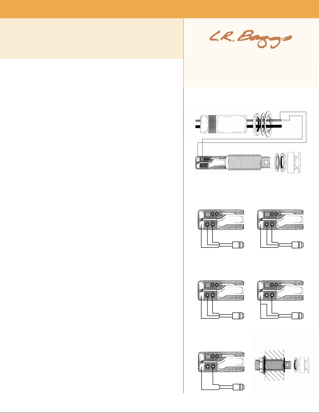
fig. 1
tip side
ring side
pickup ground bra id
hot
2. Sol deri ng: The jack is instal led onto the guita r from the insid e; solder the
pick up and mic wir es to the jack before inserting it int o the instru ment. We
recomm en d us ing a c loth to prote ct the ins trumen t's f inish d urin g sol derin g.
3. Conn ection pr ocedur e: Unsc re w the meta l cap from the Buffer Jack and
thread the pick up wi re through it. Solder t he pri mar y pick up coax' s central
(hot ) wire to the square throug h-hol e, and the g round braid t o the larger
rect angular pad, as shown in fi gure 1. Clip th e end of the hot wire close to the
PC boa rd to prevent i t from touchin g th e metal cap or oth er par ts.
Now thread the cable from the seconda ry source through the ca p, and so lder
to the other set of input pads. Figures 2a-2 e show wir ing diag ra ms for many
comm on type o f min i m ics . Again, cli p all wir e ends s o the y won't tou ch
anything.
4. Inst al lati on: Scre w the ca p b ack on an d insta ll the Buffer Jack in the guitar
as follows. Remove the s trap rin g, r etainin g nut and was her from the jack.
There should be one st ar lock ing washer, o ne flat washer and a nut remain ing
on the jac k.
Brin g the jack down throug h the sound hol e, into the bod y and insert it into
the pre-dri lled hole in th e tai lbloc k. Next, usin g the inter nal nut (be su re to
includ e the flat and sta r washers) , set th e pro per dep th so ne arly al l of the
smalle r th re aded secti on to protrud e from the instrum ent (s ee fig ure 3) .
With the jack in place, lay the remai ning washer over the thr eads and attach
the ext ernal reta ining nu t until it's tig ht. Finish by attac hing th e strap ring.
Ma ke sure ph antom po wer is on for bo th chan nels of you r o utboar d
preamp /mixer. On the M ixpr o, you' ll ne ed to remove the cover and s et th e tw o
phanto m power s witche s as shown i n the mixpro manu al.
For bes t results, foll ow the instru ction s in the Mixpro man ual and adju st the
re st o f t he "un der t he h ood" c ontrol s, to opt imi ze yo ur pic kup a nd
microp hone setting s.
Note: When co mbin ing a magne tic pi ckup with the Ribbo n Transd ucer, solde r
the Rib bon to the top contacts as shown in figu re 1, and the mag netic to the
ring contact s per figure 2e. Be sure the phantom powe r to the ring cannel in
the Mixpro is i n the o ff p osition .
fig. 2a: Crown
GLM-100/W (omni)
GLM-200/E (cardoid)
tip side
s hi e ld
r ed
w hi t e
ring side
fig. 2b: Joe Mills/Sony
ECM-44pt
tip side
s hi e ld
w hi t e
r ed
ring side
fig. 2e: Mics with 2 wire output
such as AKG C406/B
tip side
fig. 2c: Countryman
Iso-Max
tip side
s hi e ld
g re e n
r ed
ring side
fig. 2d: Shure
SM-98
tip side
p in 2
s hi e ld
ring side
p in 3
fig. 3
s hi e ld
s ig n al
ring side
 Loading...