

Page 1
www.lowrance.com
Pub. 988-0151-221
LMF-400
Multi-function Gauge
Installation and Operation
Instructions
Page 2

Copyright © 2005 Lowrance Electronics, Inc.
All rights reserved.
No part of this manual may be copied, reproduced, republished,
transmitted or distributed for any purpose, without prior written
consent of Lowrance Electronics. Any unauthorized commercial
distribution of this manual is strictly prohibited.
Lowrance Electronics may find it necessary to change or end our
policies, regulations and special offers at any time. We reserve the right
to do so without notice. All features and specifications subject to change
without notice. On the cover: LMF-400 shown.
For free owner's manuals and other information,
visit our web site:
www.lowrance.com
Lowrance Electronics Inc.
12000 E. Skelly Dr.
Tulsa, OK USA 74128-2486
Printed in USA.
Page 3

Table of Contents
Section 1: Introduction ............................................................ 3
Section 2: Installation .............................................................. 5
Preparation ................................................................................... 5
Recommended Tools and supplies............................................ 5
Mounting the Unit ........................................................................ 5
Connecting to a NMEA 2000 Network..................................... 6
Network Nodes.......................................................................... 7
Adding a Network Node............................................................ 7
Additional Network Information.............................................. 8
Section 3: Operation ................................................................. 9
Boat Setup..................................................................................... 9
Pages ........................................................................................... 10
Engine Trim ............................................................................10
Diagnostics .............................................................................. 10
Fuel Manager .......................................................................... 10
GPS Position ........................................................................... 11
Single Analog .......................................................................... 11
Dual Analog............................................................................. 11
Quad Analog............................................................................ 11
Single Digital .......................................................................... 11
Dual Digital............................................................................. 12
Quad Digital............................................................................ 12
Synchronizer ........................................................................... 12
Trim Tabs ................................................................................ 12
Viewing options........................................................................... 12
Basic Menu.................................................................................. 12
Adding Pages........................................................................... 13
Removing Pages ...................................................................... 13
Page Scrolling.......................................................................... 14
Pop-Ups Setup......................................................................... 14
Screen .......................................................................................... 15
Audio Setup................................................................................. 16
System Setup .............................................................................. 17
Bus Devices .............................................................................17
To Reset Values:.................................................................. 17
Section 4: EP Configuration & Calibration ....................... 19
Temperature Sensors.............................................................. 20
To Unconfigure a temp sensor:........................................... 20
To Configure a temp sensor:............................................... 20
To Reconfigure a temp sensor: ........................................... 20
Fuel Flow (Port, Center and Stbd) ......................................... 21
1
Page 4

Fluid Level .................................................................................. 22
To unconfigure Fluid Level:.................................................... 23
Calibrate.................................................................................. 25
Reset Values............................................................................ 25
GPS Module, Paddle Wheel Speed and Trim Tabs ...............25
Calibration of EP Devices........................................................... 26
Partial Fill ........................................................................... 28
Trim Tabs ................................................................................ 28
Section 5: Advanced Operation............................................ 31
Customizing Pages...................................................................... 31
Single Analog .............................................................................. 31
Dual Analog................................................................................. 32
Quad Analog................................................................................ 32
Single Digital .............................................................................. 33
Dual Digital................................................................................. 34
Quad Digital................................................................................ 35
Trim Tabs .................................................................................... 35
GPS Position ............................................................................... 36
Fuel Manager.............................................................................. 36
Fuel Setup ............................................................................... 36
Adjust Calibration............................................................... 36
Fuel Remaining Source....................................................... 36
Reset Seasonal .................................................................... 37
Refill Tank........................................................................... 37
Partial Fill ........................................................................... 37
Economy Speed Source .......................................................37
Reset Trip Fuel ....................................................................... 37
System Setup Menu.................................................................... 38
Engine Displayed ................................................................ 38
Bus Devices ......................................................................... 38
Sonar Alarms .......................................................................... 38
Engine/Tank Configuration ................................................ 39
Reset Values: ....................................................................... 40
System Information ................................................................ 40
Speed Range ........................................................................ 40
Pressure Range ................................................................... 40
Change Units ..............................................................................41
Speed and Distance............................................................. 41
Temperature........................................................................ 41
Pressure............................................................................... 41
Depth ...................................................................................41
GPS Coordinates ................................................................. 42
Volume................................................................................. 42
2
Page 5
Section 1: Introduction
Thank you for buying the Lowrance LMF-400! Your unit is a highquality, multi-function, digital gauge designed to work with a
LowranceNET network. This is the NMEA 2000
developed by Lowrance Electronics.
Caution:
Installing LowranceNET NMEA 2000 devices is significantly
different from installing earlier Lowrance components without
NMEA 2000 features. You should read all of the installation
instructions before proceeding.
This gauge will only work with a NMEA 2000 network. It MUST be
connected to a NMEA 2000 network or it WILL NOT function. When
properly installed, the LMF-400 will display information from a variety
of Lowrance Electronic Probe (EP) sensors connected to the network.
networking system
A NMEA 2000 network using LowranceNET components.
All Lowrance NMEA 2000 capable devices are either NMEA 2000
certified or certification is pending. See our web site,
for the latest product status information.
To get started with your Lowrance gauge, first read the installation
section. It contains instructions for installing the LMF-400.
After you've read those instructions, install the gauge and any EP
sensors you may have purchased, then read the rest of this manual.
Each sensor comes with its own installation instruction sheet, but this
manual describes how the gauge operates with each sensor, and how to
calibrate the sensors. The more you know about the gauge, the better it
will work for you.
Your package also includes another manual, part 988-0154-172, which
contains complete instructions for creating or expanding a NMEA 2000
network.
3
www.lowrance.com,
Page 6

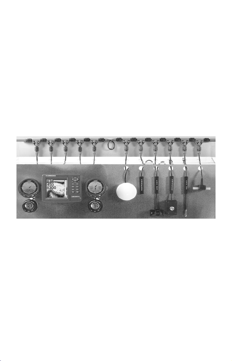
LowranceNET teams up the powerful NMEA 2000 network standard
with a fast-growing, cutting-edge family of Lowrance Electronic Probe
Sensors. At press time, the product line includes the EP-10 Fuel Flow,
EP-15 Fluid Level, EP-20 Engine interface, EP-25 Speed, EP-35 Temp
and EP-45 Water Pressure sensors.
And what's more exciting, there are others on the way! Be sure to log
onto
www.lowrance.com from time to time for the latest developments,
including updated operation manuals and instruction sheets you can
download free of charge. When you're ready to expand your network,
see the accessory ordering information on the back cover of this
manual.
NOTICE!
The storage and operation temperature range for your unit is from
-4 degrees to +167 degrees Fahrenheit (-20 degrees to +75 degrees
Celsius). Extended storage or operation in temperatures higher or
lower than specified will damage the liquid crystal display in your unit.
This type of damage is not covered by the warranty. For more
information, contact the factory's Customer Service Department; phone
numbers are inside the manual's back cover.
4
Page 7
Section 2: Installation
Preparation
The design of the LMF-400 allows convenient mounting in the dash of
your boat, or it can be mounted on any flat panel at least four inches in
diameter.
To mount the LMF-400 in the dash, first make sure there is sufficient
clearance behind the panel in the desired location. Also, see that there is
adequate room to connect power and transducer cables. At least 3-1/2 inches
are needed behind the surface of the dash to clear all connectors and wiring.
Recommended Tools and supplies
Recommended tools for this job include: hole saw, drill, drill bit (for
starter hole). Required supplies for this job include: "U" bracket, lock
washers and wing nuts (included).
Mounting the Unit
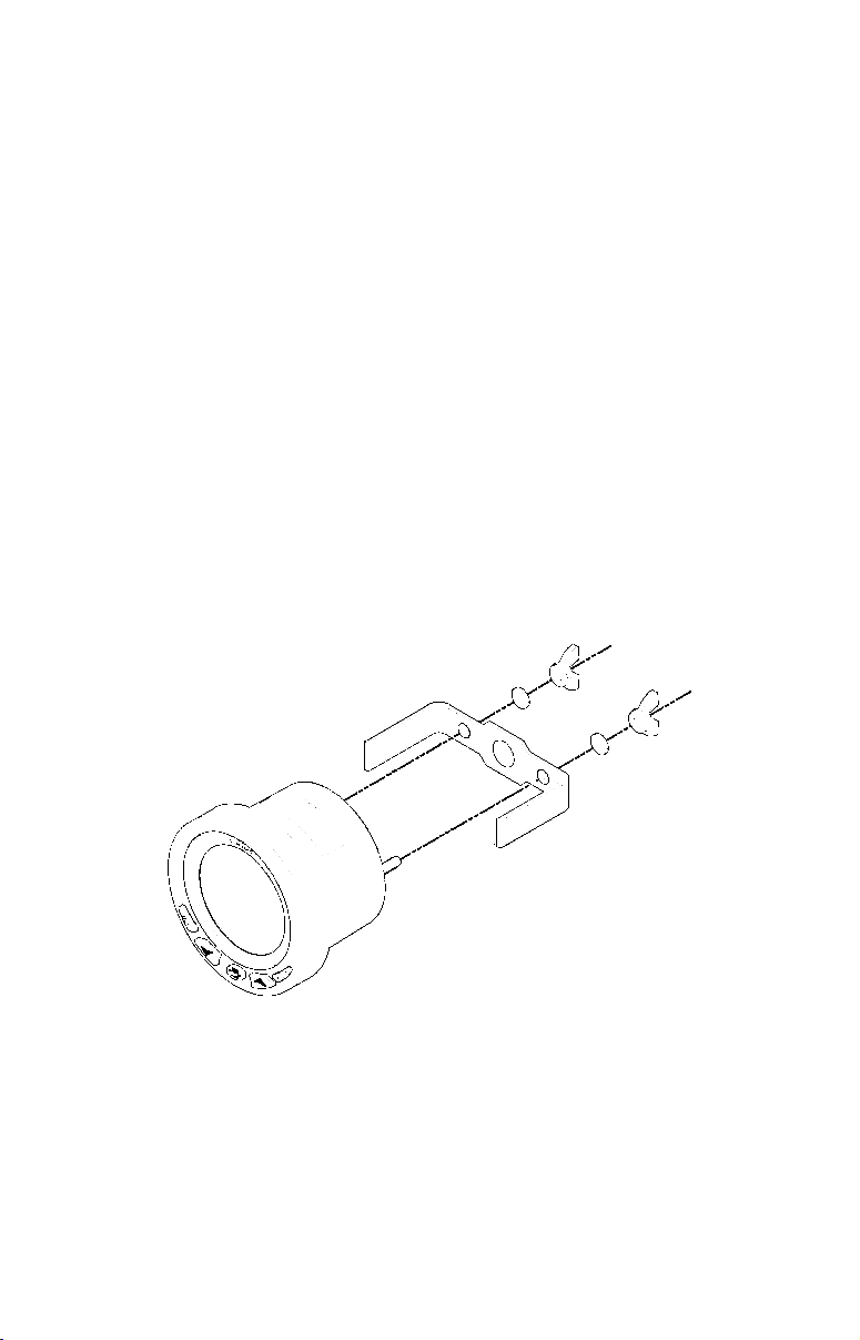
Cut a 3-3/8 inch diameter mounting hole with a hole saw. A "U" bracket
is supplied to hold the sonar to the dash. Place it over the threaded
studs on the back of the unit and secure it with the lock washers and
nylon wing nuts provided with the unit.
Secure unit to the dash using "U" bracket as shown.
The bracket is designed to secure the unit to a dash with a thickness of
2 mm. If your dash is thicker than 2 mm, the "U" bracket will be too
long. Simply place washers or spacers between the unit and the bracket
until you can tighten the wing nuts and secure the unit in place. Once
the unit is in place, you need to connect it to a power supply, to the
speaker (provided) and the LowranceNET.
5
Page 8
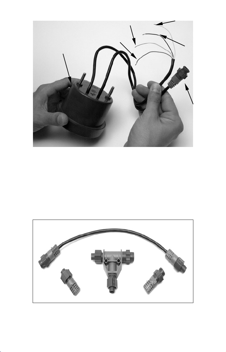
Yellow wire:
Piezo ground
Blue wire:
LMF-400
Housing
LMF-400 with power cable wiring and NMEA 2000 Cable Connection.
Piezo positive
White wire:
Dash light
positive
Black wire:
Dash light
ground
LMF-400
NMEA
2000
Network
Cable
Connecting to a NMEA 2000 Network
A network bus is an installed and operational network cable (backbone)
running the length of your boat, already connected to a power supply
and properly terminated. Such a bus provides network connection
nodes at various locations around your boat.
This is similar to the telephone wiring in a house. If you pick up a
phone in your living room, you can hear someone talking into the phone
in the bedroom.
LowranceNET Node Kit for a NMEA 2000 network. Includes a 2 foot
extension cable, T connector, 120-ohm male terminator and 120-ohm
female terminator.
6
Page 9
For complete instructions on setting up a new NMEA 2000 network or
expanding an existing one, see the other document packed with your
gauge, "Setup and Installation of NMEA 2000 Networks, General
Information" part number 988-0154-172. If that document is missing, it
can be downloaded free from the Lowrance web site.
Network Nodes
A network bus is built of network nodes spread along a backbone.
Network nodes are made by fitting T-shaped connectors into the
backbone (using the sockets on the sides), and attaching a display unit or
sensor at the bottom of the "T."
Using our telephone example, the T connectors are similar to telephone
jacks. The backbone is like the phone wiring running through a house.
Phones in a house must be connected to each other to communicate, and
in the same way only sensors and display units plugged into the NMEA
network can share information.
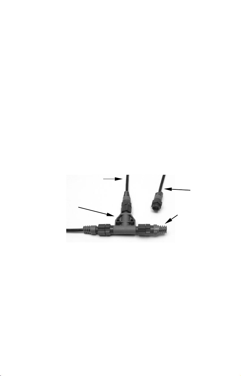
Connections found in the middle of the bus will have one or more of these
T-shaped connectors with the backbone cables plugged into both sides.
Connections at the end of a network will have the backbone plugged into
one side, and a terminator plugged into the other, as shown in the
following figure.
Cable from
sensor or
display unit
LEI or Lowrance
device needs an
open T.
T connector
Backbone cable
(to rest of bus)
NMEA 2000 network node located at the end of a NMEA 2000 bus.
Terminator at
the very end
of the bus
Adding a Network Node
You can add a node anywhere along the network backbone where a
connection already exists. This connection could be at the end of the
network (between a T connector and a terminator), between two T
connectors, between a T connector and a backbone extension cable, or
between two extension cables. Wherever you want to add the new node,
simply separate the sockets of the old connection and attach your new T
connector between them.
7
Page 10
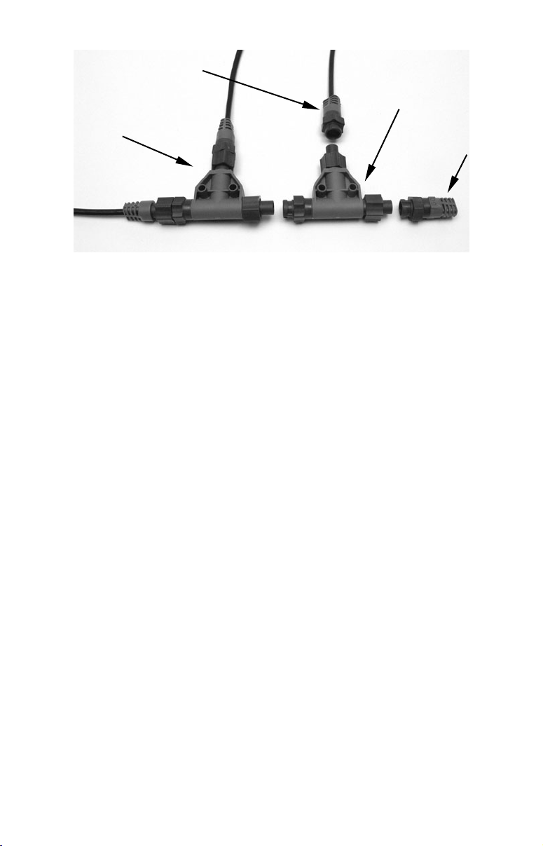
Lowrance or LEI device con-
nects to new T connector.
Existing network
node
Add a new device to a NMEA 2000 bus by attaching a T connector
between two T connectors, between a T connector and the end
terminator, or between two backbone extension cables.
Add T-shaped connector to add device
to bus.
Attach
terminator at
end of bus.
If you want to add a node at the end of the line (as shown in the previous
figure), remove the terminator from the very last connector, securely
attach the new T connector, and then attach the terminator on the new
connector. Either method will allow you to add a device.
Additional Network Information
Further instructions on creating or expanding a LowranceNET network
are illustrated in the NMEA 2000 network setup booklet, part number
988-0154-172, which came packed with this manual.
8
Page 11
Section 3: Operation
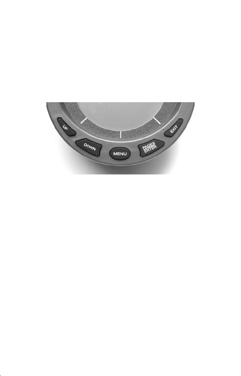
The displays and settings in this digital gauge are controlled by a fivebutton keypad. The buttons are
EXIT. The MENU key calls up the basic menu, which allows you to set up
as many as 16 pages for display. The
scroll through and highlight menu items. The
referred to as the
ENTER key) allows you to scroll forward through a
series of pages and is used to select items from menus. The
used to close menus and scroll backward through a series of pages.
LMF-400 keypad.
Boat Setup
When the LMF-400 powers up for the first time, the screen will show
the
Boat Setup menu. You will not be able to proceed without
completing Boat Setup, which requires you to program into the unit the
number of engines and gas tanks on your vessel. Boat Setup will only
appear again if you reset Engine/Tank configuration, add certain EP
sensors or if configuration is lost.
To complete Boat Setup:
1. With Boat Setup highlighted, press
allowing you to choose the number of engines and fuel tanks on your
vessel. The Boat Setup menu options are: 1 Eng/1 Tank, 1 Eng/2 Tank,
2 Eng/1 Tank, 2 Eng/2 Tanks, 3 Eng/1 Tank or
2. Choose the option that applies to your vessel and press ENTER. After
setting the engine/tank configuration, you will need to enter the size of
each tank via the Set Tank Size menu. It will appear with up to three
options, depending on the number of tanks you chose during Boat
Setup. The options are: Port Tank, Stbd Tank and Cen Tank.
3. Select the tank you want to set up and press
the Setting Tank Size window. If you selected one tank during Boat
Setup, you will be taken directly to the Setting Tank Size Window.
UP, DOWN, MENU, PAGES/ENTER and
UP and DOWN keys are used to
PAGES/ENTER key (also
EXIT key is
ENTER. A menu will appear,
3 Eng/3 Tanks.
ENTER. That will launch
9
Page 12
4. Use the
hold and press
UP and DOWN keys to enter how many gallons the tank will
ENTER.
Press EXIT and repeat steps 3 and 4 for each of the remaining tanks.
5. After all tanks on your vessel have been setup, press EXIT repeatedly
to be directed back to the main display.
NOTE:
If your LMF-400 was already installed on your boat you likely will
not have to complete boat setup. But, if you would like to go
through the setup, take a look at the following instructions.
1. Press
Select
MENU, scroll down to SYSTEM SETUP, then press ENTER.
ENG/TANK CFG and press ENTER|ENTER.
2. The following message will appear: Press Enter to Reset
Eng/Tank Cfg. Press
directed to the Boat
press
ENTER to access the engine/tank configuration menu.
ENTER to reset the configuration and be
Setup screen. From the Boat Setup screen,
Pages
Pages are the backbone of the LMF-400. They give you the power to
mix and match data that will be displayed on the screen. Once you have
picked pages that meet your preferences, the 400's multi-functionality
really kicks in, allowing you to customize pages with the data most
important to you. We'll take a closer look at customizing pages in
Section 5: Advanced Operation.
The LMF-400 has the capability to support up to 16 pages, which
means you can add pages you find most helpful more than once,
customizing each one differently.
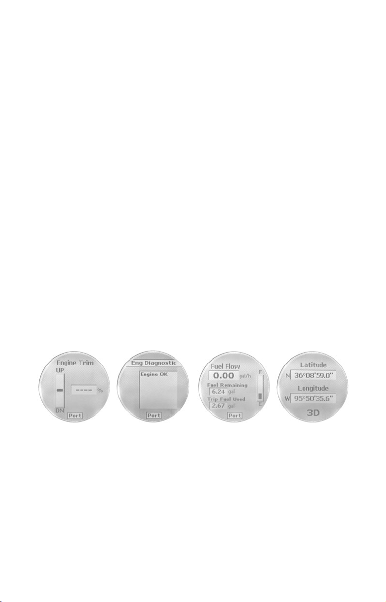
Engine Trim (from left to right), Diagnostics, Fuel Manager and GPS
Module page.
Engine Trim
Monitors position of the boat’s engine in either percentages or degrees.
Diagnostics
Monitors engine performance, notifying you if a problem arises.
Fuel Manager
Fuel Manager page has three digital readouts capable of displaying:
Fuel Flow, Fuel Economy, Fuel Remaining, Fuel Range, Trip Fuel
Used, Seasonal Fuel, Paddle Wheel Speed, Pitot Speed and GPS Speed.
10
Page 13

GPS Position
The GPS position page displays the boater’s position in LatitudeLongitude, using Degrees-Minutes-Seconds or Degrees-Minutes as
units of measure.
Single Analog (from left to right), Dual Analog, Quad Analog and
Single Digital page.
Single Analog
The single analog page displays an analog gauge that can show: Alt
Voltage, Battery Voltage, Engine Temp, Atmospheric Pressure,
Temperature, Fluid Level, PaddleWheel Speed, Pitot Speed, GPS Speed
and Tachometer.
Dual Analog
The Dual Analog page shows a pair of analog gauges that can display:
Alt Voltage, Battery Voltage, Engine Temperature, Atmospheric
Pressure, Temperature, Fluid Level, Paddle Wheel Speed, Pitot Speed,
GPS Speed and Tachometer.
Quad Analog
The Quad Analog page displays four analog gauges that can monitor:
Alt Voltage, Battery Voltage, Engine Temperature, Atmospheric
Pressure, Temperature, Paddle Wheel Speed, Pitot Speed, GPS Speed
and Tachometer.
Single Digital
The Single Digital page displays a digital gauge that can monitor: Alt
Voltage, Battery Voltage, Engine Temperature, Atmospheric Pressure,
Temperature, Depth, Engine Load, Total Engine Hours, Fuel Flow,
Fuel Economy, Fuel Remaining, Fuel Range, Paddle Wheel Speed, Pitot
Speed, GPS Speed and Tachometer.
11
Page 14

Dual Digital (from left to right), Quad Digital, Synchronizer and Trim
Tabs page.
Dual Digital
The Dual Digital page features a pair of digital gauges which can
display: Alt Voltage, Battery Voltage, Engine Temp, Atmospheric
Pressure, Temperature, Depth, Engine Load, Total Engine Hours, Fuel
Flow, Fuel Economy, Fuel Remaining, Fuel Range, Paddle Wheel
Speed, Pitot Speed, GPS Speed and Tachometer.
Quad Digital
The Quad Digital page has four digital gauges capable of displaying:
Alt Voltage, Battery Voltage, Engine Temperature, Atmospheric
Pressure, Temperature, Depth, Engine Load, Total Engine Hours, Fuel
Flow, Fuel Economy, Fuel Remaining, Fuel Range, Paddle Wheel
Speed, Pitot Speed, GPS Speed and Tachometer.
Synchronizer
The Synchronizer page will show RPM for up to three engines, allowing
users to synchronize the engines for smoother performance.
Trim Tabs
The Trim Tab page monitors the position of the Trim Tabs using either
percentages or degrees as units of measure.
Viewing options
The pages may be viewed on the screen in one of two ways. You can
scroll through them manually by using the
ENTER and EXIT keys or set
them to scroll automatically via the Page Scrolling function. We'll
explore Page Scrolling in greater detail later in this section.
NOTE:
The
ENTER and EXIT keys work together to help you scroll through
pages on the main display. Pressing the
in one direction. Pushing the
EXIT key moves the scroll in the other
ENTER key moves the scroll
direction.
Basic Menu
Each page has its own menu. The menus vary somewhat from page to
page, but all include these basic menu categories: Page, Screen, Audio
Setup and
System Setup.
12
Page 15
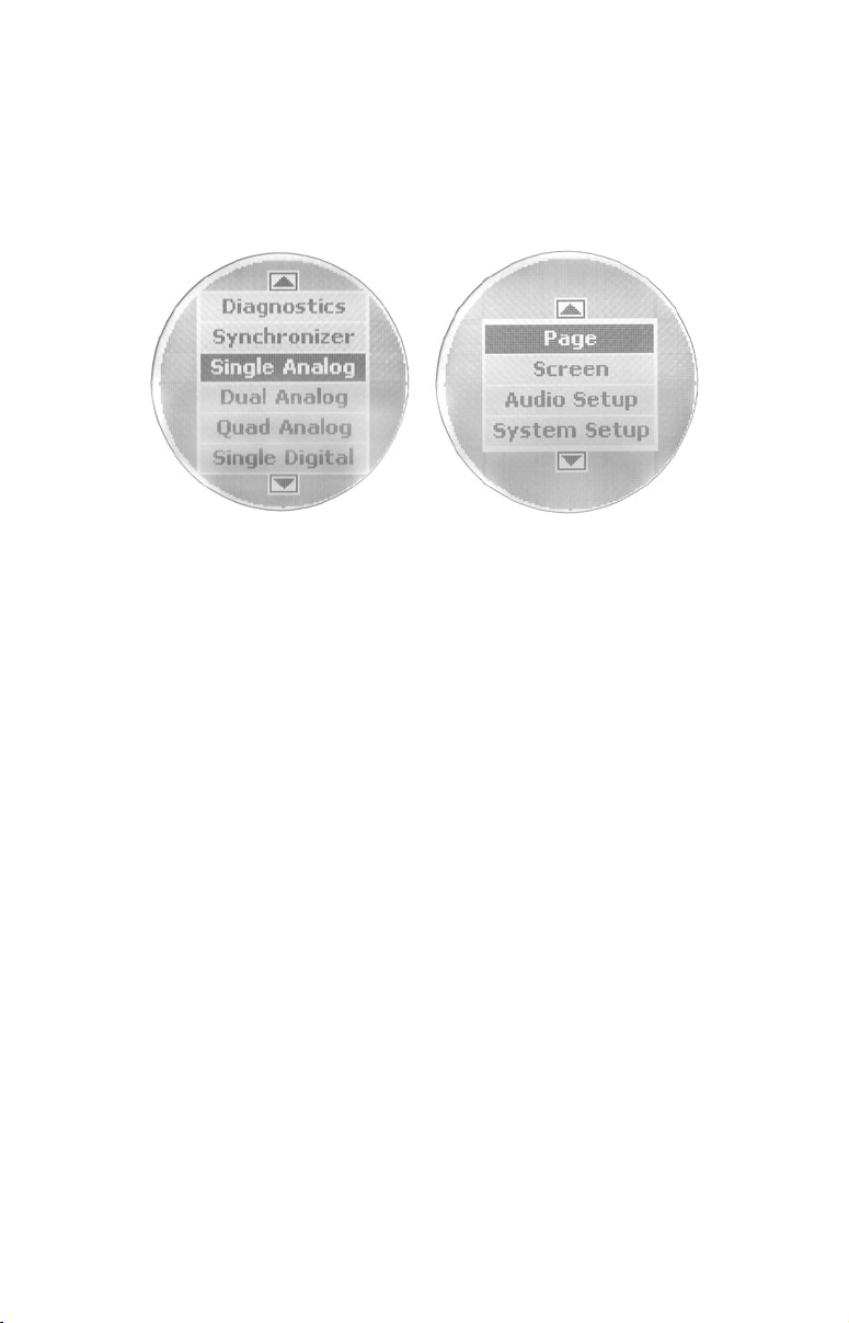
The pages may be displayed one at a time or in a timed scroll set at an
interval of your choosing via the page
scrolling setting.
NOTE:
The System Setup menu is the lone basic menu category that
differs slightly from page to page, depending on the page being
displayed. We'll delve into that later in this section.
Scrolling list of page options (left) with basic menu categories (right).
Adding Pages
To add a page to the display:
1. Press
four options: Add Page, Remove Page, Page Scrolling and
MENU, select PAGES and press ENTER. A menu will pop up with
Pop-Ups
Setup.
2. Select
ADD PAGE and press ENTER. Use the UP and DOWN keys to
scroll through the list.
3. You can select the page you want to display by pressing
ENTER when
the desired page is highlighted. An adding page prompt will appear
asking you to press the
ENTER key to add the page.
4. Press ENTER to add the page, which will take you back to the main
display, where the page you selected will be on the screen.
5. If you choose not to add the selected page, press
EXIT repeatedly to
return to the main display.
Removing Pages
To remove a page from the display:
1. Press
2.
Choose REMOVE PAGE and press ENTER. You won't have a list to choose
MENU, select PAGES and press ENTER.
from, like when we added a page. You will only be able to remove the
page that was on the main display when you pressed the
MENU key.
The following prompt will appear: Press Enter to Remove current Page.
3. Press
ENTER, which will return you to the main display.
4. If you decide not to remove the selected page, press EXIT repeatedly
to return to the main display.
13
Page 16

Page Scrolling
Once you have added the pages you want to monitor, you'll have two
ways to view them on the display. You can scroll through the pages
manually by using the
ENTER and EXIT keys or utilize the Page
Scrolling function to automatically scroll through the pages at an
interval of your choosing.
To activate Page Scrolling:
1. Press
MENU, select PAGES and press ENTER.
2. Select PAGE SCROLLING and press ENTER. The Page Scrolling menu will
appear with two settings: Off
and Set Time.
3. To set the scrolling interval, choose SET TIME and press ENTER.
4. Use the UP and DOWN keys to select an interval between one and 60
seconds. At the bottom of the Set Time display will be a message, Press
Enter when finished. After you are satisfied with the selected interval,
press
ENTER.
To turn off Page Scrolling:
To get back into the Page Scrolling menu, repeat the steps you used to
activate Page Scrolling.
But this time, when you access the Page Scrolling menu, select
OFF
instead of SET TIME.
Pop-Ups Setup
Pop-Ups Setup is accessed from the basic menu by selecting
pressing
options will appear: RPM, Engine Trim, Trim Tabs and
ENTER. Scroll down to Pop Ups Setup and press ENTER. Four
Stay-on Time.
PAGES and
The Pop-Ups feature makes it possible for you to be alerted when the
category you selected (RPM, Engine Trim, Trim Tabs) exceeds a
threshold of your choosing. When a threshold is exceeded, the main
page for the category will pop up on the main display for a preset
duration. You can choose how long the page will be displayed via the
Stay-on Time option.
RPM: If you highlight
will appear: Off and Set Threshold. Select
or highlight Set Threshold and press
RPM and press ENTER, a pair of menu options
OFF to turn off a RPM pop up
ENTER, to set a RPM threshold.
The threshold for RPM ranges from 50 to 3,000 RPM.
Engine Trim: If you select
options will appear: Off and Set
Engine Trim pop up or highlight Set Threshold and press
ENGINE TRIM and press ENTER, a pair of menu
Threshold. Select Off to turn off an
ENTER, to set
an Engine Trim threshold. The threshold for Engine Trim ranges from
3% to 50%.
Trim Tabs: If you choose
options will appear: Off and Set Threshold. Select
TRIM TABS and press ENTER, a pair of menu
OFF to turn off a Trim
14
Page 17

Tab pop up or highlight Set Threshold and press
ENTER, to set a Trim
Tab threshold. The threshold for Trim Tabs ranges from 3% to 50%.
Stay-on Time: By highlighting Stay-on Time you are able choose how
long the RPM, Engine Trim and Trim Tab pages will be displayed when
their respective thresholds have been exceeded. To set the duration of
each display, highlight
STAY-ON TIME and press ENTER. The Set Time
menu will appear, giving you the option to select a duration between 2
and 15 seconds. You need only set the Stay-on Time duration once since
it will affect all three categories (RPM, Engine Trim and Trim Tabs).
Basic menu with Screen highlighted (left). Screen option menu
(center) with Set Backlight window (right).
Screen
To access the Screen menu:
1. Press
from which to choose: Backlight, Contrast
Adjusting Backlight:
1. Select
backlight. A vertical adjustment bar will appear on the Set Backlight
window. If more than one gauge is on the bus, it will automatically
adjust the other gauge to the same setting.
2. Use the
3. Press
main display.
Adjusting Contrast:
You can adjust the Contrast in the same manner as the Backlight.
1. Select
Contrast Adjust window.
2. Use the
3. Press
to the main display.
MENU, choose SCREEN and press ENTER. There are three options
and Reverse Video.
BACKLIGHT and press ENTER to adjust the brightness of the
UP and DOWN keys to set the backlight to a desired level.
EXIT to return to the Screen menu or ENTER to get back to the
CONTRAST from the Screen menu and press ENTER to launch the
UP and DOWN keys to move the slider bar to a desired level.
EXIT to return to the Screen menu or press ENTER to get back
15
Page 18

Contrast is highlighted on the Screen menu (left). The Contrast Adjust
window (center). Reverse Video highlighted on Screen menu (right).
The easiest way to change the look of the display is to utilize the
Reverse Video command, commonly used for nighttime viewing.
To select Reverse Video:
1. From the screen menu, highlight
REVERSE VIDEO and press ENTER.
You'll notice the dark and light colors have been swapped for one
another. The white text, which was on top of a dark background, now
has been switched to dark text on top of a white background. If more
than one gauge in on the bus, it will automatically adjust the other
gauge to the same setting.
2. To toggle back to the previous setting, return to the Screen menu,
select
REVERSE VIDEO and press ENTER.
3. Press
EXIT|EXIT to return to the main display.
Audio Setup highlighted on the basic menu (left). Audio
Setup menu (center) with Key Sounds menu (right).
Audio Setup
To modify audio settings:
1. Press
appear with two options: Key Sounds and Alarm Sound.
Adjusting Key Sounds:
2. Select
MENU, highlight AUDIO SETUP, then press ENTER. A menu will
KEY SOUNDS and press ENTER.
16
Page 19

3. Select
ON or OFF and press ENTER, which will take you back to the
main display.
4. If you choose to keep the current setting, press
EXIT to return to the
Audio Setup menu
Adjusting Alarm Sounds:
1. To turn on or turn off Alarm Sounds, select
Audio Setup menu and press
2. Select
ON or OFF and press ENTER, which will take you back to the
ENTER.
ALARM SOUNDS from the
main display.
3. If you choose to keep the current setting, press
AUDIO SETUP menu.
4. Press
EXIT repeatedly to return to the main display.
EXIT to return to the
System Setup
On each page, the System Setup menu contains, Engine Displayed,
Change Units, Bus Devices, Sonar Alarms, Eng/Tank Configuration,
Reset Values
To access the System Setup menu, press
DOWN keys to highlight SYSTEM SETUP, then press ENTER. We’ll discuss
the System Setup menu in more detail in the Advanced Operation
section.
Bus Devices
One of the more significant commands in the System Setup menu is the
Bus Devices command. It allows you to run a system check for all
devices connected to the LowranceNet.
1. To run a system check for devices connected to the NMEA 2000
LowranceNet, press
BUS DEVICES and press ENTER. After a Searching for Bus Devices
message comes up, a list of all devices attached to the LowranceNET —
the Bus Devices list — will appear.
NOTE:
If you modify settings and are not satisfied with the results, you
can reset the gauge to its factory default settings via the Reset
Values command.
To Reset Values:
1. Press
2. Scroll down to
will appear: Press Enter to reset all values.
3. Press
and System Information.
MENU and use the UP and
MENU, select SYSTEM SETUP and press ENTER. Choose
MENU, highlight SYSTEM SETUP and press ENTER.
RESET VALUES and press ENTER. The following message
ENTER to reset the values.
17
Page 20

WARNING:
Resetting values is a factory hard reset. All settings will
be wiped out.
NOTE:
Resetting values does not affect engine/tank configuration or the
calibration and configuration settings of devices on the bus.
18
Page 21

Section 4: EP Configuration &
Calibration
To configure items linked into the LowranceNET networking system,
MENU and select SYSTEM SETUP. Highlight BUS DEVICES and press
press
ENTER, which will bring up the message, Searching Bus Devices. Once
all devices are detected, a list of the devices (Bus Devices list) will be
displayed.
The Bus Devices command acts as the device manager for the bus,
allowing you to configure and unconfigure devices and set and reset
critical values such as alarms and calibration.
Bus Devices highlighted in the System Setup menu (left). Searching
Bus Devices window (center) with Bus Devices list (right).
NOTE:
Devices will vary in name and number depending on what has been
connected to the LowranceNET. The number of temp sensors
attached to the network will match the number that comes up on
the Bus Devices list.
If you configure or reconfigure a sensor, you're assigning or reassigning
its designation in the LMF-400 to a different sensor location on the
boat.
The following items can be configured, unconfigured or reconfigured:
Temperature Sensors (UnCfg Temp), Fuel Flow Sensors (UnCfg F
Flow) and Fluid Level (UnCfg F Level). When UnCfg Temp, UnCfg F
Flow and the UnCfg Fluid Level appear on the bus devices list it shows
they are unconfigured. Proceed through this section to configure each
one. You can have multiple Temperature sensors and Fluid Level
Tanks, but will have no more than three Fuel Flows to configure since
the LMF-400 supports a maximum of three engines.
The GPS Module and Paddle Wheel Speed do not need to be configured.
Engines and tanks are configured through the System Setup menu.
Trim Tabs are configured through the Pages menu, which will be
addressed later in this section.
19
Page 22

NOTE:
If you configure the desired sensors and are not satisfied with the
results, you may clear the configuration settings for each sensor
individually, by resetting values from the sensor's configuration
menu. Remember, ONLY the sensor you select from the Bus
Devices list will be set back to its defaults. To reset the LMF-400 to
its defaults, you must select
Menu. We'll take a closer look at the
RESET VALUES from the System Setup
RESET VALUES command later in
this section.
To get to the configuration menu:
1. Press
2. Highlight
detected in the network will be listed. Use the
MENU, select SYSTEM SETUP and press ENTER.
BUS DEVICES and press ENTER. After a few moments, items
UP and DOWN keys to
scroll through the list.
3. To configure an item in the list, highlight the item and press
ENTER.
Temperature Sensors
When temperature sensors are selected from the Bus Devices menu,
the temp sensor configuration menu comes up with two choices:
UNCONFIGURE or RECONFIGURE.
To Unconfigure a temp sensor:
1. After selecting a temp sensor from the Bus Devices list and pressing
ENTER, choose UNCONFIGURE from the configuration menu and press
ENTER. The following message will appear: Hit Menu to UnCfg Temp
Sns.
2. Press
ENTER to unconfigure the sensor and be directed back to the
Bus Devices list.
To Configure a temp sensor:
1. If you highlight
UNCFG TEMP and press ENTER, a window will pop up
asking if you want to configure the sensor.
2. Press
ENTER to be taken to the Selecting Temp menu.
3. Highlight one of the Temp options (Temp1, Temp 2, Temp 3, etc.) on
the Selecting Temp menu and press
ENTER. The UnCfg temp now has
been configured as the Temp you selected. You automatically will be
redirected to the Bus Devices list.
To Reconfigure a temp sensor:
If you want to reconfigure a sensor, but all the sensors linked to the
LowranceNET are already configured, you must first unconfigure a
sensor, so its name will be available. Otherwise a Name Already
Selected message will appear.
20
Page 23

In the following example, we want to swap the configuration of Temp 2
and Temp 1. We will first unconfigure Temp 2, then reconfigure Temp 1
as Temp 2. We'll finish by configuring UnCfg Temp (formerly Temp 2)
as Temp 1.
1. Highlight
TEMP 2 on the Bus Devices list and press ENTER, which will
launch the temp sensor configuration menu.
2. Choose
UNCONFIGURE and press ENTER. The following message will pop
up: Hit Menu to UnCfg Temp Sns.
3. Press
4. Select
RECONFIGURE and press ENTER. That will direct you to the Temp
ENTER, and you will be taken back to the Bus Devices list.
TEMP 1 from the Bus devices menu and press ENTER. Choose
Selection menu.
5. Select
TEMP 2 and press ENTER, which will take you back to the Bus
Devices list.
6. Now highlight
UNCFG TEMP from the Bus Devices list and press ENTER,
which will call up the Selecting Temp menu. Choose one of the Temp
options (Temp 1, Temp 3, etc.) and press
ENTER. You will be returned to
the Bus Devices list.
NOTE:
To run a system check for devices connected to the NMEA 2000
network, select
ENTER. A Searching Bus Devices message comes up, followed by a
BUS DEVICES from the System Setup menu and press
list of all devices attached to the LowranceNET — the Bus Devices
list. To select an item from the bus devices list, use the
DOWN keys to scroll through the list. Highlight the desired category
and press
ENTER.
UP and
Fuel Flow (Port, Center and Stbd)
Port Fuel Flow (Port Fflow), Center Fuel Flow (Cen Fflow) and
Starboard Fuel Flow (Stbd Fflow) all share the same internal
configuration menu, which includes: Change Engine (for two or more
engines only), Fuel Warning, Unset Engine and Reset Values. After
selecting a Fuel Flow (Port, Center or Stbd) from the Bus Device list
and pressing
ENTER, the following options will appear in the menu.
To Unconfigure Fuel Flow:
See Unset Engine below.
To Configure Fuel Flow:
1. From the Bus Devices list, highlight
UNCFG F FLOW and press ENTER.
That will launch the following message: Hit Menu to Cfg Flow Sns.
2. Press
ENTER to proceed with configuration.
21
Page 24

To Change Engine (Reconfigure; active only with multiple-engine setting):
1. From a fuel flow menu, select
CHANGE ENGINE and press ENTER. That
will call up an internal menu with three options: Port, Center and
Starboard. When you select one of the three options a message appears:
Changing Device Settings. When the LowranceNET has been scanned
and all devices have been detected, you will be directed back to the Bus
Device list.
To set Fuel Warning:
1. Highlight FUEL WARNING and press ENTER, which opens a menu with
the following options: Low Level or High Level.
2. After choosing either
Level Warning window will appear. It will be set to
When setting a Fuel Warning, you should choose
HIGH LEVEL or LOW LEVEL and pressing ENTER, a
OFF by default.
LOW LEVEL, which will
warn you when the fuel level drops below a preset percentage of the
tank's capacity.
3. To set the Fuel Warning level, use the
desired percentage and press
ENTER. You then will be directed back to
UP and DOWN keys to select a
the Bus Devices list.
To Unset Engine (Unconfigure):
1. After highlighting UNSET ENGINE and pressing ENTER, a message will
pop up: Press Ent to Unconfig Dev Instance.
2. Press ENTER and you will be directed back to the Bus Devices list.,
where UnCfg F Flow will now be displayed.
To Reset Values:
1. Choose RESET VALUES, press ENTER and a message will be displayed:
Press Enter to Reset Device Values.
2. Press
ENTER to reset the device values to the default settings.
NOTE:
By resetting values from the configuration menu, ONLY the device
selected from the Bus Devices list will be set back to its defaults.
When you Reset Values, the calibration on the device is reset. But
when you unconfigure a device, its calibration is unaffected.
WARNING:
If you reset any EP, that EP will lose all configuration
and calibration.
Fluid Level
Up to three tanks for each Fluid Level category (Fuel, Fresh Water, Oil,
Black Water, Waste Water and Live Well) can be supported by the
LMF-400. On the Bus Devices list, the fuel tanks will be displayed as
Fuel Tank (P) for portside, Fuel Tank (C) for center and Fuel Tank (S)
for starboard.
22
Page 25

If you have one tank it will be shown as Fuel Tank. Other tanks will be
displayed as Blackwater Tank, Freshwater Tank, Oil Tank, Live Well
Tank and Waste Water Tank. If you have more than one of the tank
types above, it will be displayed as Blk Wtr 1, 2, 3, Live Well 1, 2, 3, etc.
If the tank or tanks have not been configured, they will be listed as
Unfcg F Level.
To unconfigure Fluid Level:
1. Choose a configured Fluid Level from the Bus Devices list and press
ENTER.
2. Highlight UNCONFIGURE and press ENTER, which will launch the
following message: Press Enter to Unconfigure Device.
3. Press
ENTER and you will be returned to the Bus Devices list where
you now will see UnCfg F Level on the devices list.
To Configure Fluid Level:
1. Select
which will launch the following message: Press
UNFCG F LEVEL from the Bus Devices list and press ENTER,
ENTER to configure
Fluid Level Sensor.
2. Press
ENTER and a menu will be called up with these configuration
options: Fuel, Fresh Water, Waste Water, Live Well, Oil and Black
Water. You can have up to three tanks for each category.
NOTE:
The gauge must be set to Fuel Level for the Fuel Remaining Source
to display fuel level sensor information properly. For more
information on the topic, see Fuel Remaining source under Fuel
Setup in Section 5, Advanced Operation.
To configure Fuel:
1. Highlight FUEL from the list of configuration options and press ENTER.
The number of options on the menu will vary with the number of tanks
you selected during Boat Setup. See Boat Setup on the first page of
Section 3: Operations.
If you have three tanks, a menu will appear with these options: Port
Tank, Cen (Center) Tank and
Stbd (Starboard) Tank.
2. Highlight one of the three tank options and press ENTER, which will
take you back to the Bus Devices list. If you have more than one tank,
one of the following will now be on the list: Fuel Tank (P), Fuel Tank
(C), Fuel Tank (S). If you have one tank, Fuel Tank will be on the list.
To configure Fresh Water:
1. Choose FRESH WATER from the list of configuration options and press
ENTER. A window will appear prompting you to input the tank number.
2. Enter the tank number (1, 2 or 3) and press ENTER. That will launch
a tank size window.
23
Page 26

3. Use the
hold and press
UP and DOWN keys to enter how many gallons the tank will
ENTER. You will then be directed back to the Bus
Devices list.
To configure Waste Water:
1. Highlight WASTE WATER from the list of configuration options and
press
ENTER. A window will appear prompting you to input the tank
number.
2. Enter the tank number (1,2 or 3) and press
ENTER, which will launch
a tank size window.
3. Use the
hold and press
UP and DOWN keys to enter how many gallons the tank will
ENTER. The Changing Device Settings window will
appear. You will then be directed back to the Bus Devices list.
To configure Live Well:
1. Choose LIVE WELL from the list of configuration options and press
ENTER, which will launch a window prompting you to input the tank
number.
2. Enter the tank number (1,2 or 3) and press
ENTER, which will launch
a tank size window.
3. Use the
ENTER. You will then be directed back to the Bus Devices list.
To configure Oil:
UP and DOWN keys to enter the size of the tank and press
1. Highlight OIL from the list of configuration options and press ENTER,
which will launch a menu with these options: Port Tank, Cen Tank
and
Stbd Tank.
2. Select a tank and press
ENTER, which will call up a Setting Tank
Size window.
3. Use the
will hold and press
UP and DOWN keys to enter the number of gallons the tank
ENTER. You will then be returned to the Bus
Devices List.
To configure Black Water:
1. Highlight BLACK WATER from the list of configuration options and
press
ENTER, which will launch a window prompting you to input the
tank number.
2. Enter the tank number (1, 2 or 3) and press
ENTER, which will call
up a tank size window.
3. Use the
hold and press
UP and DOWN keys to enter how many gallons the tank will
ENTER. You will then be directed back to the Bus
Devices list.
To Reconfigure Fluid Level:
1. Select a configured Fluid Level (Fuel Tank, Oil Tank, Black Water
Tank, Waste Water Tank, Fresh Water Tank, Live Well Tank) from the
Bus Devices list and press
ENTER.
24
Page 27

A menu will be displayed with the following options: Level Warning,
Unconfigure, Reconfigure, Calibrate and Reset Values.
To set Level Warning:
1. Select
LEVEL WARNING and press ENTER, which will open a menu with
two options: Low Level or High Level.
2. Choose one of the levels (Low or High) and a box will appear,
allowing you to set the warning level you selected to Off or to a desired
percentage.
NOTE:
If you configure a tank for fuel, you should choose a
LOW LEVEL
warning, which will warn you when the fuel level drops below a
preset percentage of the tank's capacity. Fresh Water and Oil also
should be set for Low Level. If you configure a tank for Black Water
or Waste Water, you should configure the Level Warning to the
LEVEL. For example, if the High Level warning is set to 3 quarters of
HIGH
a tank, you will be notified before the tank's capacity has been
exceeded, allowing you to dump the tanks before they fill up.
3. Use the
desired level and press
UP and DOWN keys to set the warning percentage to a
ENTER, then you will be returned to the Bus
Devices list.
Calibrate
See detailed information on Calibration later in this section.
Reset Values
1. Highlight
ENTER. The following message will appear: Hit Menu to Rst Values.
RESET VALUES on the Tank configuration menu and press
2. Press ENTER to reset the Tank device configuration values to the
default setting. This will remove any calibration previously set.
NOTE:
By resetting values from the configuration menu, ONLY the device
selected from the Bus Devices list will be set back to its defaults.
When you Reset Values, the calibration on the device is reset. But
when you unconfigure a device, its calibration is unaffected.
WARNING:
If you reset any EP, that EP will lose all configuration
and calibration.
GPS Module, Paddle Wheel Speed and Trim Tabs
The remaining items from the Bus Devices list, GPS Module, Paddle
Wheel Speed and Trim Tab Sensors do not need to be configured. If you
highlight GPS Module or Paddle Wheel Speed and press
ENTER, the
following message should appear: Device Working Properly.
25
Page 28

Trim Tab Sensors: highlighting Trim Tab Sensors and pressing ENTER,
will launch the following message: Press Enter to Reset Device Values.
To reset the Trim Tab Sensor settings to the default setting, press
ENTER.
Calibration of EP Devices
Calibrating Fluid level is an important step to ensuring the status of
your tank is correctly transmitted over the NMEA 2000 bus.
For example: if you have an odd-shaped tank, like one that is wider at
the top than at the bottom, the float inside the tank will tell you there
is a half tank of gas when it reaches the midpoint of the tank,
regardless of the tank’s actual capacity below the midpoint. That could
cause you to run out of gas more quickly than expected. Whether the
tank is configured for Fuel, Fresh Water, Waste Water, Black Water or
Oil, calibrating the Fluid Level protects you from unpleasant surprises.
NOTE:
To run a system check for devices connected to the NMEA 2000
network, select
ENTER. A Searching Bus Devices message comes up, followed by a
list of all devices attached to the LowranceNET — the Bus Devices
list. To select an item from the bus devices list, use the
DOWN keys to scroll through the list. Highlight the desired category
and press
To calibrate a tank:
1. Press
MENU, select SYSTEM SETUP and press ENTER.
2. From the System Setup menu, highlight
to bring up the Bus Devices list.
3. From the devices list, highlight the fluid level source you want to
calibrate, press
appear with three calibration options: 2 point, 3 point and 5 point.
To execute
2-Point Calibration: there will be a pair of settings in the 2-
point calibration menu: Empty Level and Full Level. 2-Point calibration
is best for rectangular or square shaped tanks that allow the fuel level
sensor to provide an accurate reading of the fuel level at the top and
bottom of the tank.
1. Choose the level (
tank's current fuel level and press
If you choose F
Set Tank to Full Level Press Enter.
2. Press
3. Press
ENTER and you will be taken back to the 2-point menu.
EXIT to return to the Bus Devices list.
BUS DEVICES from the System Setup menu and press
UP and
ENTER.
BUS DEVICES and press ENTER
ENTER, select CALIBRATE and press ENTER. A menu will
EMPTY OR FULL LEVEL) that corresponds with your
ENTER.
ULL LEVEL, the following message will appear: Calibrating
26
Page 29

To execute 3-Point Calibration: there will be three options in the 3-point
calibration menu: Empty Level, Half Level and Full Level. 3-point
calibration is designed for tanks that vary in shape from the top to the
bottom, leading to an inaccurate fuel level sensor reading, in the
narrower, bottom portion of the tank.
1. Choose the level
tank's current fuel level and press
following message will appear: Calibrating Set Tank to Half
(EMPTY, HALF OR FULL LEVEL) that corresponds with your
ENTER. If you choose half level, the
Level Press
Enter.
2. Press
3. Press
To execute 5-point Calibration: there will be five options in the 5-point
ENTER and you will be taken back to the 3-point menu.
EXIT to return to the Bus Devices list.
calibration menu: Empty Level, 1 Qtr Level, Half Level, 3 Qtr Level
and Full Level. 5-point calibration is designed for the most uniquely
formed tanks that vary greatly in shape from top to bottom, making an
accurate fuel level sensor reading impossible without calibration.
1. Choose the level (
corresponds with your tank's current fuel level and press
EMPTY, 1 QTR, HALF, 3 QTR or FULL LEVEL) that
ENTER. If you
chose 3-quarter level, the following message will appear: Calibrating
Set Tank to 3 Qtr Press Enter.
2. Press
3. Press
ENTER and you will be directed back to the 5-point menu.
EXIT to return to the Bus Devices list.
Fuel Flow
If using the EP-10 Fuel Flow as the Fuel Remaining source, you must
tell the unit when you add fuel or fill the tank. If just adding fuel, but
not topping off the tank, use the
PARTIAL FILL option and enter the
amount of fuel added.
WARNING:
Be sure to carefully follow these instructions, otherwise
fuel calibration could be inaccurate, resulting in
incorrect Fuel Flow, Fuel Remaining, Fuel Economy and
Fuel Range readings.
If you are topping off the tank, but do not want or need to calibrate the
unit, select the
FILL TANK option and choose NO on the Calibrate option.
To calibrate the EP-10 Fuel Flow, you must use the Refill Tank option.
1. First, fill up the vessel's tank, but do not recalibrate, just input that
the tank has been refilled.
2. Once you have burned at least 5 gallons of fuel, fill up the tank
again, carefully noting how much fuel was added to top off the tank.
The amount of fuel added should be very close to the amount of Fuel
27
Page 30

Used shown by the gauge. If the difference between these two figures is
greater than 5 percent, then you need to recalibrate the unit.
3. To do this, after entering the tank has been refilled, select
RECALIBRATE option.
YES on the
4. Then enter in the amount of fuel added to fill the tank. The
calibration is calculated by comparing the actual fuel used to the
calculated fuel used. It is vital to get an accurate reading on the actual
fuel used and the amount of fuel added to fill the tank the second time.
On multiple engine installations with a single tank configuration, only
one engine should be run when calibrating the EP-10 Fuel Flow. This is
the only way to know how much fuel has gone through the EP-10 Fuel
Flow you want to calibrate.
Refill Tank
1. After you have filled the gas tank, scroll through the pages until the
Fuel Manager page is on the main display. Press
2. Highlight
3. Scroll down the menu to
FUEL SETUP and press ENTER.
REFILL TANK and press ENTER, which will call
MENU.
up the following message: ReCalibrate? A menu will be below the
message with two options: Yes or No.
4. Highlight
YES and press ENTER, which will launch the Filled Fuel
Quantity window.
5. Use the
the tank and press
UP and DOWN keys to enter the number of gallons you put in
ENTER to finalize the calibration. You will be
directed back to the Fuel Setup menu.
Partial Fill
1. Scroll through the pages until the Fuel Manager page is on the
screen, then press
2. Highlight
3. Scroll down to
MENU.
FUEL SETUP and press ENTER.
PARTIAL FILL and press ENTER, which will launch the
Adding Fuel Window.
4. Use the
the tank, then press
UP and DOWN keys to enter the amount of fuel you added to
ENTER. You will be directed back to the Fuel Setup
menu.
Trim Tabs
If the Trim Tabs have not been calibrated or have been reset, the
display will flash between 0 and 100. This is normal prior to the trim
tabs being calibrated for the first time.
Trim Tabs can only be calibrated from the Trim Tabs page. If the page
is not present in the scrolling page display, add the Trim Tab page by
following the Adding Pages instructions in Section 3: Operation.
28
Page 31

1. Scroll through the displayed pages until the Trim Tab page is on the
main display.
2. Press
MENU, select CALIBRATE TAB and press ENTER, which will launch
the following message: Bring Tabs Full Up Press Enter.
3. Adjust the position of the Trim Tabs to the Full Up Position and
ENTER. A second message will appear: Run Tabs Full DN (Down).
press
4. Move the Trim Tabs into the full down position. The Trim Tabs are
now calibrated. Recalibration can be performed at any time and as
many times as necessary by following the step by step trim tab
calibration instructions listed in this section.
Trim Tabs menu (left). When calibrating Trim Tabs, the Full Up
message (center) appears first. It is followed by the Run Tabs Full
Down message (right).
29
Page 32

Notes
30
Page 33

Section 5: Advanced Operation
Customizing Pages
In this section, we're going to take a look at how each of the pages can
be customized.
NOTE:
In order to access a page-specific menu make sure the desired page
is on the display when you press the menu button. The page menus
have a lot of similarities, but many have specific menu categories
that only will appear on the basic menu if accessed while that page
is on the main screen. For example, if you wanted to access the Fuel
Manager menu, then you must scroll through the pages until the
Fuel Manager page is displayed on the screen before pressing
MENU.
Basic menu with Customize highlighted.
Single Analog
A single gauge display, the Single Analog page may be customized to
monitor any of the following: Alt Voltage, Battery Voltage, Engine
Temp, Atmospheric Pressure, Temperature, Fluid Level, PaddleWheel
Speed, Pitot Speed, GPS Speed and Tachometer.
To customize the Single Analog page:
1. Scroll through the pages set for display by pushing the
key.
2. Once the Single Analog page is displayed, press
CUSTOMIZE and press ENTER.
3. Scroll through the device list and highlight the category you want to
monitor, then press
displayed on the screen.
ENTER. The information you selected will be
31
ENTER or EXIT
MENU, select
Page 34

NOTE
The System Setup menu for all three analog gauges feature Speed
Range and Pressure Range. A more detailed description of Speed
Range and Pressure range may be found under System Setup later
in this section.
Single Analog page (left) with Dual Analog page (right).
Dual Analog
A pair of analog gauges, the Dual Analog page may be customized to
show information from any of the following: Alt Voltage, Battery
Voltage, Engine Temperature, Atmospheric Pressure, Temperature,
Fluid Level, Paddle Wheel Speed, Pitot Speed, GPS Speed and
Tachometer.
To customize the Dual Analog page:
1. Scroll through the pages set for display by pushing the
ENTER or EXIT
key.
2. Once the Dual Analog page is displayed, press MENU, select CUSTOMIZE
and press ENTER.
3. A menu prompt will appear giving you the option to customize the
Top Gauge or the Bottom Gauge. Use the
highlight the desired gauge and press
ENTER.
UP and DOWN keys to
4. Scroll through the device list and highlight the category you want to
monitor, then press
ENTER. This will take you back to the menu
prompt. If you want to customize the other portion of half of the gauge
repeat the steps above, otherwise press
EXIT, EXIT. The information you
selected will be displayed on the screen.
Quad Analog
A display featuring four analog gauges, the Quad Analog page
supports: Alt Voltage, Battery Voltage, Engine Temperature,
Atmospheric Pressure, Temperature, Paddle Wheel Speed, Pitot Speed,
GPS Speed and Tachometer.
32
Page 35

To Customize the Quad Analog page:
1. Scroll through the pages set for display by pushing the
ENTER or EXIT
key.
2. Once the Quad Analog page is displayed, press MENU, select
CUSTOMIZE and press ENTER.
3. A menu prompt will appear giving you the option to customize the
gauge on the Top Left, Top Right, Bottom Left or Bottom Right.
4. Use the
customize and press
UP and DOWN keys to highlight the gauge you want to
ENTER.
5. Scroll through the device list and highlight the desired item, then
press
ENTER. This will take you back to the gauge menu prompt. If you
want to customize any of the other gauges, repeat the steps above,
otherwise press
EXIT, EXIT. The information you selected will be
displayed on the main screen.
NOTE:
If a page is customized to show information from a device that is
working improperly or is not connected to the NMEA 2000 network,
the data boxes on the gauge will flash. This indicates the device is
not sending data to the Bus. This could occur for a variety of
reasons, depending on the device type. If it is a GPS sensor, the
GPS unit probably has not locked on to a satellite yet and may take
a few moments to acquire a position. All other EP sensors need to
be configured, which may be done via Bus Devices in the System
Setup menu.
Quad Analog page (left) with Single Digital page (right).
Single Digital
The single digital page displays a single digital gauge that can display:
Alt Voltage, Battery Voltage, Engine Temperature, Atmospheric
Pressure, Temperature, Depth, Engine Load, Total Engine Hours, Fuel
Flow, Fuel Economy, Fuel Remaining, Fuel Range, Paddle Wheel
Speed, Pitot Speed, GPS Speed and Tachometer.
33
Page 36

To customize the Single Digital page:
1. Scroll through the pages set for display by pushing the
ENTER or EXIT
key.
2. Once the Single Digital page is displayed, press
CUSTOMIZE and press ENTER.
MENU, select
3. Scroll through the device list and highlight the category you want to
monitor, then press
ENTER. The information you selected will be
displayed on the main screen.
Dual Digital
The Dual Digital page features a pair of digital gauges which can
monitor: Alt Voltage, Battery Voltage, Engine Temp, Atmospheric
Pressure, Temperature, Depth, Engine Load, Total Engine Hours, Fuel
Flow, Fuel Economy, Fuel Remaining, Fuel Range, Paddle Wheel
Speed, Pitot Speed, GPS Speed and Tachometer.
To customize the Dual Digital page:
1. Scroll through the pages set for display by pushing the
key.
2. Once the Dual Digital page is displayed, press
MENU, select CUSTOMIZE
and press ENTER.
3. A menu prompt will appear give you the option to customize Top
Data or Bottom Data. Use the
you want to change and press
UP and DOWN keys to highlight the data
ENTER.
4. Scroll through the list and highlight the category you want to
monitor, then press
ENTER. This will take you back to the menu
prompt. If you want to customize the other data, repeat the steps
above, otherwise press
EXIT, EXIT. The information you selected will be
displayed on the main screen.
ENTER or EXIT
Dual Digital page (left) with Quad Digital page (right).
34
Page 37

Quad Digital
The Quad Digital page has four digital gauges capable of displaying:
Alt Voltage, Battery Voltage, Engine Temperature, Atmospheric
Pressure, Temperature, Depth, Engine Load, Total Engine Hours, Fuel
Flow, Fuel Economy, Fuel Remaining, Fuel Range, Paddle Wheel
Speed, Pitot Speed, GPS Speed and Tachometer.
To Customize the Quad Digital page
:
1. Scroll through pages set for display by using the ENTER or EXIT key.
2. Once the Quad Digial page is displayed, press MENU, select CUSTOMIZE
and press ENTER.
3. A menu prompt will appear giving you the option to customize Data
Box 1, Data Box 2, Data Box 3 or Data Box 4.
4. Use the
customize and press
UP and DOWN keys to highlight the data box you want to
ENTER.
5. Scroll through the device list and highlight the category you want to
monitor, then press
ENTER. This will take you back to the menu
prompt. If you want to customize any of the other boxes, repeat the
steps above, otherwise press
EXIT|EXIT. The box you customized will
display the data you selected.
Trim Tabs
The Trim Tab page can display Trim Tabs position in percentages and
degrees, giving boaters precise control of Trim Tab position.
To Customize Trim Tabs:
1. Scroll through the pages set for display, pressing
Trim Tab page is on the main display.
2. Select
CUSTOMIZE and press ENTER.
3. There will be two choices: Percentage or Degrees.
4. Choose the desired unit of measure and press ENTER. The Trim Tab
page displays position information in the unit of measure you chose.
MENU when the
Trim Tabs page (left), GPS Module page (center) and Fuel Manager
Page (right).
35
Page 38

GPS Position
Displays user position in Latitude/Longitude.
Fuel Manager
The Fuel Manager page has three digital readouts capable of
displaying: Fuel Flow, Fuel Economy, Fuel Remaining, Fuel Range,
Trip Fuel Used, Seasonal Fuel, Paddle Wheel Speed, Pitot Speed and
GPS Speed. While on the Fuel Manager page, press
Fuel manager menu, which contains the following options: Customize,
Fuel Setup, Pages, Screen, Audio Setup and System Setup.
NOTE
If you have multiple engines, you must go into System Setup and
select Engine Displayed. Here you can select the engine you want to
set up. The Fuel Management page shows the engine you selected
at the bottom of the page.
To Customize the Fuel Manager Page:
1. Scroll through pages set for display using the
2. Once the Fuel Manager page is displayed, press
CUSTOMIZE and press ENTER.
3. The menu prompt will appear with the follow options: Top Data,
Center Data and Bottom Data. Use the
the data box you want to customize and press
UP and DOWN keys to highlight
ENTER.
4. Scroll through the list and highlight the desired item, then press
ENTER. This will take you back to the menu prompt. If you want to
customize other data, repeat the steps above, otherwise press
EXIT. The information you selected will be displayed on the screen.
Fuel Setup
1. To access the Fuel Setup menu, press
MENU while viewing the Fuel
Manager page, which will bring up the Fuel Manager page menu.
2. Select
FUEL SETUP, then press ENTER.
The Fuel Setup menu contains the following categories: Adjust
Calibration, Fuel Remaining Source, Reset Seasonal, Refill Tank,
Partial Fill, Eco Speed Source and
Reset Trip Fuel.
Adjust Calibration
1. From the Fuel Setup menu, select
2. Use the
adjustment, then press
UP and DOWN keys to input the desired calibration
ENTER.
ADJUST CAL and press ENTER.
Fuel Remaining Source
The Fuel Remaining Source menu prompts you to choose what sensor
will be used to monitor your fuel level. There are two options: Engine
Fuel Flow and
Fluid Level Sensor.
36
MENU to access the
ENTER and EXIT keys.
MENU, select
EXIT,
Page 39

From the Fuel Setup menu, select
FUEL REM SRC and press ENTER.
1. Highlight your preference — ENG/FFLOW or FLUID LEV SNSR — and press
ENTER. Press EXIT repeatedly to get back to the main display.
Reset Seasonal
The LMF-400 has the capability to track fuel usage not only for trips,
but also for entire seasons. The reset seasonal option allows you to
reset the running tally of seasonal fuel usage to zero.
1. From the Fuel Setup menu, select
RST SEASONAL and press ENTER. The
following message will appear: Press Enter to reset Seasonal Fuel.
2. Press
ENTER to reset seasonal fuel or press EXIT to return to the Fuel
Setup menu.
Refill Tank
The Refill Tank category gives you the option of re-calibrating after you
have filled the fuel tank.
1. From the Fuel Setup menu, select
REFILL TANK and press ENTER. The
following message will appear: Press Enter after refilling the fuel tank.
If you choose to recalibrate, a window will pop up, asking you to enter
the amount of fuel you put into the tank. Use the
enter the fuel amount and press
ENTER.
UP and DOWN keys to
Partial Fill
Partial Fill helps maintain the accuracy of the Fuel Remaining and
Fuel Range figures, by allowing you to input into the unit the amount
of fuel added to the tank.
1. From the Fuel Setup menu, select
PARTIAL FILL and press ENTER. An
Adding Fuel window will appear.
2. Use the
the tank and press
UP and DOWN keys to enter the amount of fuel you added to
ENTER.
Economy Speed Source
Economy Speed source allows you to select the speed source that will be
factored into the Fuel Economy equation.
1. From the Fuel Setup menu, select
ECO SPEED SRC and press ENTER,
which will call up the Economy speed Source menu with the following
options: Paddle Wheel Speed, Pitot Speed andGPS Speed.
2. Select one of the three options and press
ENTER, which will take you
back to the Fuel Management display. Paddle Wheel Speed is best
suited for low speeds, while Pitot Speed will work best at high speeds.
GPS Speed works well at both high and low speeds.
Reset Trip Fuel
Reset Trip Fuel allows you to reset to zero the running tally of how
much fuel you have used on a particular trip.
37
Page 40

1. From the Fuel Setup menu, select
RST TRIP FUEL and press Enter,
which will launch the following message: Press Enter to Reset Trip
Fuel.
2. Press
EXIT repeatedly to return to the main display.
ENTER, which will take you back to the Fuel Setup menu. Press
System Setup Menu
To get to the System Setup menu, press MENU, then scroll down to
System Setup and press
Engine Displayed, Bus Devices, Sonar Alarms, Eng/Tank
Configuration, Reset Values, System Information and Change Units.
Engine Displayed
The Engine Displayed command allows you to monitor up to three
engines on your vessel.
ENTER. The System Setup menu contains:
Basic menu with System Setup highlighted (left). System Setup menu
(right) with Engine Displayed selected.
1. After accessing the System Setup menu, highlight ENGINE DISPLAYED
and press ENTER. A menu will appear with the following options: Port,
Center and Starboard. This is important when viewing information like
Fuel Management, RPM and Engine Voltage.
2. Select the engine you would like to monitor and press
ENTER.
Bus Devices
1. To run a system check for devices connected to the NMEA 2000
network, choose
ENTER. After a Searching for Bus Devices message comes up, a list of
BUS DEVICES from the System Setup menu and press
all devices attached to the LowranceNET — the Bus Devices list — will
appear.
Sonar Alarms
1. If you would like to set Deep or Shallow Sonar Alarms, select
ALARMS from the System Setup menu and press ENTER. An alarm menu
SONAR
will pop up with two choices: Shallow or Deep.
38
Page 41

2. In this example, we'll select
SHALLOW and press ENTER. A small menu
will appear, giving you the option to turn off the alarm or set the depth.
3. Select
SET DEPTH and press ENTER.
4. Use the UP and DOWN keys to select the desired depth and press
ENTER. To set the Deep alarm, press EXIT, select DEEP from the alarms
menu and press the
Sonar Alarms highlighted on System Setup menu (left). Sonar Alarms
menu (center); Reset Values selected on System Setup menu (right).
ENTER key.
5. Choose SET DEPTH, then use the UP and DOWN keys to set the alarm to
the desired depth. Press
ENTER|EXIT|EXIT to return to the System
Setup menu.
Engine/Tank Configuration
1. From the System Setup menu, scroll down to
ENTER. Boat Setup will be highlighted. Press ENTER, which will bring
ENG/TANK CFG and press
up the following message: Press Enter to reset Eng/Tank Cfg. Press
ENTER.
3. The Boat Setup title bar will appear on the screen. Press
ENTER to
access the Boat Setup menu. The Boat Setup menu options are: 1 Eng/1
Tank, 1 Eng/2 Tank, 2 Eng/1 Tank, 2 Eng/2 Tanks, 3 Eng/1 Tank or 3
Eng/3 Tanks.
4. Choose the option that applies to your vessel and press
ENTER, which
will bring up the Set Tank Size menu. It will appear with up to three
options, depending on the number of tanks you chose during Boat
Setup. The options are: Port Tank, Stbd Tank and Cen Tank.
(If you
selected one tank during Boat Setup, you won't see any of these options.
You will be taken directly to the Setting Tank Size Window.)
5. Select the tank you want to set up and press
ENTER, which will
launch the Setting Tank Size window.
6. Use the
hold and press
UP and DOWN keys to enter how many gallons the tank will
ENTER.
Press EXIT and repeat steps 3 and 4 for each of the remaining tanks.
7. After all tanks on your vessel have been setup, press EXIT repeatedly
to be directed back to the main display.
39
Page 42

Reset Values:
1. Press
2. Scroll down to
MENU, highlight SYSTEM SETUP and press ENTER.
RESET VALUES and press ENTER. The following message
will appear: Press Enter to reset all values.
3. Press
ENTER to reset the values.
NOTE:
Resetting Values will not clear Engine/Tank configuration or the
settings of EP sensors previously calibrated or configured.
System Information
The system information screen provides information about the version
and build of the software in your LMF-400.
1. To access system information, select
Setup menu and press
ENTER. The system information will be
SYSTEM INFO from the System
displayed on the screen.
NOTE:
The System Setup menu for all three analog gauges feature Speed
Range and Pressure Range.
Speed Range
1. To access the Speed Range menu, press
MENU when a single, dual or
quad analog page is on the main display.
2. Scroll down to
3. Select Speed Range and press
SYSTEM SETUP and press ENTER.
ENTER. The Speed Range menu has
three options: 0-40, 0-80 and 0-120.
4. Choose the desired range and press
ENTER, which will take you back
to the main display.
Pressure Range
1. To access the Pressure Range menu, press Menu when a single, dual
or quad analog page is on the main display.
2. Scroll down to
3. Select Pressure Range and press
SYSTEM SETUP and press ENTER.
ENTER, which will launch the
Pressure Range menu, which five options: Engine Water Pressure,
Engine Oil Pressure, Fuel Pressure, Engine Boost Pressure and
Transmission Oil Pressure.
4. Choose one of the options and press
ENTER. A menu will appear with
the following PSI ranges: 0-15 psi, 0-30 psi, 0-60, 0-80 psi and 0-100 psi.
5. Select the desired range and press
ENTER, which will take you back
to the main display.
40
Page 43

Change Units
From the System Setup menu, select CHANGE UNITS and press ENTER.
The
CHANGE UNITS menu has six units of measure from which to choose:
Speed/Distance, Temperature, Pressure, Depth, GPS Coordinates and
Volume.
System Setup menu (left) with Change Units highlighted. The Change
Units menu (right) with Speed/Distance selected.
Speed and Distance
1. From the Change Units menu, select
ENTER to switch its unit of measure to Statute, Nautical or Metric
units.
2. Select one of the three options and press
back to the main display.
Temperature
1. To toggle Temperature units between Fahrenheit and Celsius, choose
TEMPERATURE from the Change Units menu and press ENTER.
2. Use the
press
UP and DOWN keys to choose either FAHRENHEIT or CELSIUS and
ENTER, which will take you back to the main display.
Pressure
1. From the Change Units menu, select
2. Use the
ENTER, which will direct you back to the main display.
UP and DOWN keys to choose either PSI or BARS and press
Depth
1. To switch the unit of measure for depth to Feet, Fathoms or Meters,
select
DEPTH from the Change Units menu and press ENTER.
2. Use the UP and DOWN keys to choose an option — FEET, FATHOMS or
METERS — and press ENTER, which will take you back to the main
display.
SPEED AND DISTANCE and press
ENTER, which will take you
PRESSURE and press ENTER.
41
Page 44

GPS Coordinates
1. From the Change Units menu, select
ENTER.
GPS COORDINATES and press
2. Choose either, DEG/MIN or DEG/MIN/SEC and press ENTER, which will
take you back to the main display.
Volume
1. To change the way fluids are measured, select
Change Units
menu and press ENTER.
VOLUME from the
2. Choose either, US GALLONS or LITERS and press ENTER, which will take
you back to the main display.
42
Page 45

LOWRANCE ELECTRONICS
FULL ONE-YEAR WARRANTY
"We," "our," or "us" refers to LOWRANCE ELECTRONICS, INC., the manufacturer of
this product. "You" or "your" refers to the first person who purchases this product as a
consumer item for personal, family or household use.
We warrant this product against defects or malfunctions in materials and workmanship,
and against failure to conform to this product's written specifications, all for one (1) year
from the date of original purchase by you. WE MAKE NO OTHER EXPRESS
WARRANTY OR REPRESENTATION OF ANY KIND WHATSOEVER CONCERNING
THIS PRODUCT. Your remedies under this warranty will be available so long as you can
show in a reasonable manner that any defect or malfunction in materials or
workmanship, or any non-conformity with the product's written specifications, occurred
within one year from the date of your original purchase, which must be substantiated by
a dated sales receipt or sales slip. Any such defect, malfunction, or non-conformity which
occurs within one year from your original purchase date will either be repaired without
charge or be replaced with a new product identical or reasonably equivalent to this
product, at our option, within a reasonable time after our receipt of the product. If such
defect, malfunction, or non-conformity remains after a reasonable number of attempts to
repair by us, you may elect to obtain without charge a replacement of the product or a
refund for the product. THIS REPAIR, OR REPLACEMENT OR REFUND (AS JUST
DESCRIBED) IS THE EXCLUSIVE REMEDY AVAILABLE TO YOU AGAINST US FOR
ANY DEFECT, MALFUNCTION, OR NON-CONFORMITY CONCERNING THE
PRODUCT OR FOR ANY LOSS OR DAMAGE RESULTING FROM ANY OTHER
CAUSE WHATSOEVER. WE WILL NOT UNDER ANY CIRCUMSTANCES BE LIABLE
TO ANYONE FOR ANY SPECIAL, CONSEQUENTIAL, INCIDENTAL, OR OTHER
INDIRECT DAMAGE OF ANY KIND.
Some states do not allow the exclusion or limitation of incidental or consequential
damages, so the above limitations or exclusions may not apply to you.
This warranty does NOT apply in the following circumstances: (1) when the product has
been serviced or repaired by anyone other than us; (2) when the product has been
connected, installed, combined, altered, adjusted, or handled in a manner other than
according to the instructions furnished with the product; (3) when any serial number has
been effaced, altered, or removed; or (4) when any defect, problem, loss, or damage has
resulted from any accident, misuse, negligence, or carelessness, or from any failure to
provide reasonable and necessary maintenance in accordance with the instructions of the
owner's manual for the product.
We reserve the right to make changes or improvements in our products from time to time
without incurring the obligation to install such improvements or changes on equipment
or items previously manufactured.
This warranty gives you specific legal rights and you may also have other rights which
may vary from state to state.
REMINDER: You must retain the sales slip or sales receipt proving the date of your
original purchase in case warranty service is ever required.
LOWRANCE ELECTRONICS
12000 E. SKELLY DRIVE, TULSA, OK 74128
(800) 324-1356
43
Page 46

How to Obtain Service…
…in the USA:
We back your investment in quality products with quick, expert service
and genuine Lowrance parts. If you're in the United States and you
have technical, return or repair questions, please contact the Factory
Customer Service Department. Before any product can be returned, you
must call customer service to determine if a return is necessary. Many
times, customer service can resolve your problem over the phone
without sending your product to the factory. To call us, use the
following toll-free number:
800-324-1356
8 a.m. to 5 p.m. Central Standard Time, M-F
Lowrance Electronics may find it necessary to change or end our
shipping policies, regulations, and special offers at any time. We reserve
the right to do so without notice.
…in Canada:
If you're in Canada and you have technical, return or repair questions,
please contact the Factory Customer Service Department. Before any
product can be returned, you must call customer service to determine if
a return is necessary. Many times, customer service can resolve your
problem over the phone without sending your product to the factory. To
call us, use the following toll-free number:
800-661-3983
905-629-1614 (not toll-free)
8 a.m. to 5 p.m. Eastern Standard Time, M-F
…outside Canada and the USA:
If you have technical, return or repair questions, contact the dealer in
the country where you purchased your unit. To locate a dealer near
you, visit our web site, www.lowrance.com and look for the Dealer
Locator.
.
44
Page 47

Accessory Ordering Information
for all countries
To order Lowrance accessories such as power cables or transducers,
please contact:
1) Your local marine dealer or consumer electronics store. Most quality
dealers that handle marine electronic equipment or other consumer
electronics should be able to assist you with these items.
To locate a Lowrance dealer near you, visit our web site,
www.lowrance.com and look for the Dealer Locator. Or, you can consult
your telephone directory for listings.
2) U.S. customers: LEI Extras Inc., PO Box 129, Catoosa, OK 74015-0129
Call 1-800-324-0045 or visit our web site www.lei-extras.com.
3) Canadian customers can write:
Lowrance/Eagle Canada, 919 Matheson Blvd. E. Mississauga, Ontario
L4W2R7 or fax 905-629-3118.
Shipping Information
If it becomes necessary to send a product for repair or replacement, you
must first receive a return authorization number from Customer
Service. Products shipped without a return authorization will not be
accepted. When shipping, we recommend you do the following:
1. Please do not ship the knobs or mounting bracket with your unit.
2. If you are sending a check for repair, please place your check in an
envelope and tape it to the unit.
3. For proper testing, include a brief note with the product describing
the problem. Be sure to include your name, return shipping address
and a daytime telephone number. An e-mail address is optional but
useful.
4. Pack the unit in a suitable size box with packing material to prevent
any damage during shipping.
5. Write the Return Authorization (RA) number on the outside of the
box underneath your return address.
6. For your security, you may want to insure the package through your
shipping courier. Lowrance does not assume responsibility for goods
lost or damaged in transit.
Page 48

Visit our web site:
Lowrance Pub. 988-0151-221 © Copyright 2005
All Rights Reserved
Printed in USA 101205 Lowrance Electronics, Inc.
 Loading...