

Page 1
988-0176-01B
HDS-5 & HDS-7
Fish Finding Sonar and GPS
Operations Guide
Page 2

Software updates for your unit.
Occassionally check the Lowrance website for free software upgrades for your
unit. Go to www.lowrance.com for the software upgrades. Select the Down-
loads option from the grey menu bar near the top of the Lowrance website
homepage. The Downloads screen will appear. Select Products Software
Updates from the list on the left side of the screen. The Products Software
Updates screen will appear. Scroll through the Product list and select your unit
to download the software update.
Page 3

Contents
Table of contents
Introduction ....................................................................................... 5
Getting Started ................................................................................. 7
Turning on the Unit ..................................................................................... 7
Keypad .......................................................................................................7
Backlight ....................................................................................................7
Cursor ........................................................................................................ 7
Language ................................................................................................... 7
Menus ........................................................................................................8
Selecting Chart Data ................................................................................ 8
Selecting a Fishing Mode .......................................................................... 9
Entering Letters in Text Boxes ................................................................... 9
Restore Defaults ...................................................................................... 10
Pages ............................................................................................... 11
Pages Screen .......................................................................................... 11
Data Overlay ............................................................................................ 12
Conguration menu ................................................................................. 16
Sonar Page .............................................................................................. 17
Chart Page ............................................................................................... 17
Radar Page .............................................................................................. 18
Info Page .................................................................................................. 18
Utilities .....................................................................................................23
Displaying Combo Pages ........................................................................ 25
Sonar Operation .............................................................................29
Viewing Sonar History ............................................................................. 29
Sonar Menu ............................................................................................. 30
Sonar Options ..........................................................................................33
Palette ...................................................................................................... 34
Log Sonar Data ........................................................................................36
1
Page 4

Contents
Chart Operation............................................................................... 39
Chart menu .............................................................................................. 40
Waypoints ................................................................................................ 42
Routes ...................................................................................................... 47
Trails ......................................................................................................... 51
Measuring Distances on Chart page ....................................................... 54
Search by Coordinates ............................................................................54
Find Chart item ........................................................................................54
Map Orientation ....................................................................................... 55
Look Ahead ..............................................................................................55
Chart categories ......................................................................................56
Navionics .................................................................................................58
Radar Operation ............................................................................. 61
Radar menu ............................................................................................. 61
Cursor position window............................................................................ 67
Radar Overlay .......................................................................................... 67
Settings Menu ................................................................................. 69
Chart Settings Menu ................................................................................ 76
Sonar Settings Menu ............................................................................... 79
Manual Mode ...........................................................................................80
Fishing Modes ......................................................................................... 81
Installation Menu ...................................................................................... 82
Keel Offset ............................................................................................... 82
Radar Settings Menu ............................................................................... 86
Fuel .......................................................................................................... 93
Alarms ......................................................................................................97
Trails ......................................................................................................... 99
Units .......................................................................................................100
Network .................................................................................................. 101
Vessels ................................................................................................... 108
Simulator ................................................................................................ 110
2
Page 5

Contents
Specications .................................................................................113
Unit Care .........................................................................................114
Troubleshooting .............................................................................115
Index ............................................................................................... 123
3
Page 6

Contents
Blank page
4
Page 7

Introduction
Introduction
Thank you for purchasing from Lowrance, the industry leader in marine technology.
This manual is packaged with a Quick Start Guide, Installation Guide, License and
Warranty booklet and NMEA 2000 Networks Installation Instructions. If any of
these documents are missing, you may acquire them via a free download at www.
lowrance.com or by contacting customer service.
Lowrance Customer Service
12000 E Skelly Dr
Tulsa, OK 74128
(800) 324-1356
Canada (800) 661-3983 or (905) 629-1614
About this manual
This manual documents how to adjust features and options in your display unit. The
information in each section follows the same sequence as your display unit’s menus.
If you would like information on how to get the most out of your unit, visit our web
site, www.lowrance.com; click on the Support tab and select Tips and Tutorials.
Manual Conventions
When you are instructed to press a button in this manual, the button will be shown
in all caps and bold text like — MENU, EXIT, ENTER, etc. If you are instructed
to select an item from a menu, the item to be selected will be listed in bold like —
Brightness, Key beeps, etc.
For example: Press MENU, select Language and press ENTER.
WARNING: When a GPS unit is used in a vehicle, the
vehicle operator is solely responsible for operating the
vehicle in a safe manner. Vehicle operators must maintain full surveillance of all pertinent driving, boating or
ying conditions at all times. An accident or collision resulting in damage to property, personal injury or death
could occur if the operator of a GPS-equipped vehicle
fails to pay full attention to travel conditions and vehicle
operation while the vehicle is in motion.
5
Page 8
Introduction
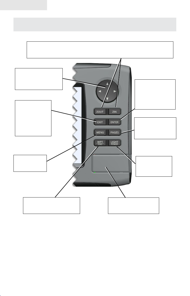
Lowrance HDS-5 and HDS-7
ZOUT: Zoom out to see more of the map with less detail
ZIN: Zoom in to see less of the map with more detail
MOB: Pressing ZOUT and ZIN at the same time will set a man overboard waypoint
KEYPAD: move the
cursor, scroll through
menus, adjust features,
view sonar/GPS history
EXIT: cancels
entries, closes
menus & windows;
toggles between
cursor position and
chart location on
Chart page
ENTER: nalize
menu selections;
shortcut key for
functions like saving
a waypoint at cursor
position
PAGES: opens Pages
menu; selects active
panel for combo
display
MENU: opens
context &
settings menus
WPT/FIND: saves a waypoint
at current position; accesses
searching tools
LIGHT/POWER:
controls backlight
level & turns the
unit on/off
MMC/SD Card slot: insert
MMC/SD and high-detail
mapping cards here
6
Page 9
Getting Started
Getting Started
Turning on the Unit
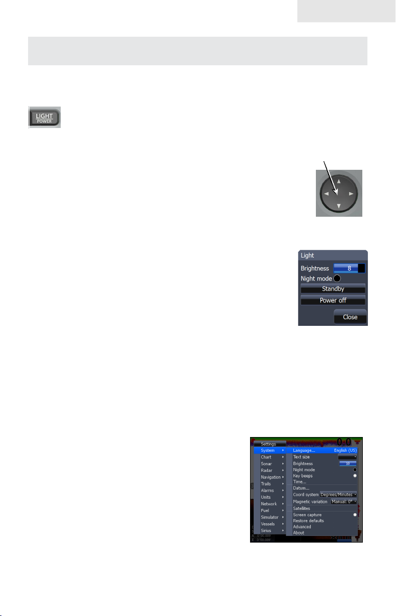
Press the POWER/LIGHT key to turn on the unit. If the unit is not connected to
a transducer, the unit will start up in simulator mode. To turn off the unit,
press the POWER/LIGHT key for three seconds.
Keypad
This unit’s keypad can be used in two ways. Pressing the arrow symbols on the keypad will move the cursor in the corresponding direction on the screen and allow you to scroll through menus.
Keypad
Backlight
Tap the LIGHT/POWER key to make adjustments to the
backlight level and open the Backlight Menu. To turn on Night
Mode from the menu, highlight Night Mode and press ENTER.
Night mode optimizes the display for low light conditions.
Cursor
Use the unit’s keypad to move the cursor around the display, select onscreen objects,
highlight data items and view sonar history. Press EXIT to remove the cursor from
the screen.
Language
Selects language used for menus, text boxes and messages.
To select a language:
Press 1. MENU twice.
Select 2. System and press ENTER
Highlight 3. Language and press ENTER.
4. Use the keypad to select a language
and press ENTER.
7
Page 10
Getting Started
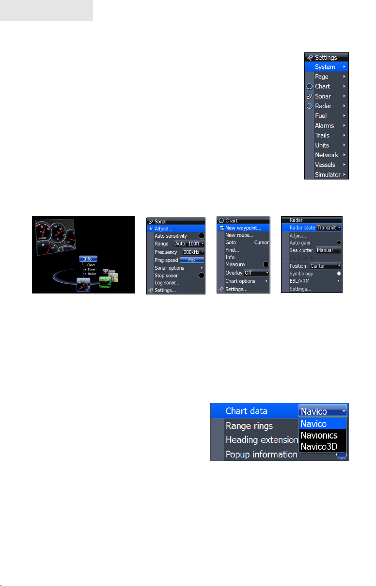
Menus
This unit has a Settings menu, a Pages screen and several context
menus. The Settings menu provides access to the settings menus for
the three main operation modes: Sonar, Chart and Radar. The Settings
menu is accessed by pressing MENU twice.
The Pages screen allows you to select a page to be shown on the
display. Utilities are also accessed from the Pages screen. Press the
PAGES key to select a page.
Each page has its own context menu which allows you to access
functions for that page. Context menus are accessible only when its
corresponding page is displayed. The Sonar Menu, for example, will
only be available when the Sonar Page is on the display. To access a
context menu, select the desired page and press the MENU key.
Settings
menu
Pages screen
Sonar menu
Chart menu
Radar menu
Closing Menus
Press the EXIT key to close a menu. Repeatedly pressing EXIT will close all menus,
taking you back to the main screen.
Selecting Chart Data
This unit supports three types of map data:
Navico, Navionics and Navico 3D (US only).
To use Navionics or Navico 3D data, you
must select it from the Chart Data menu.
To select Chart data:
Press 1. MENU twice.
Highlight 2. Chart and press ENTER.
Select 3. Chart Data and press ENTER.
Select the desired map data option and press 4. ENTER.
8
Page 11
Getting Started
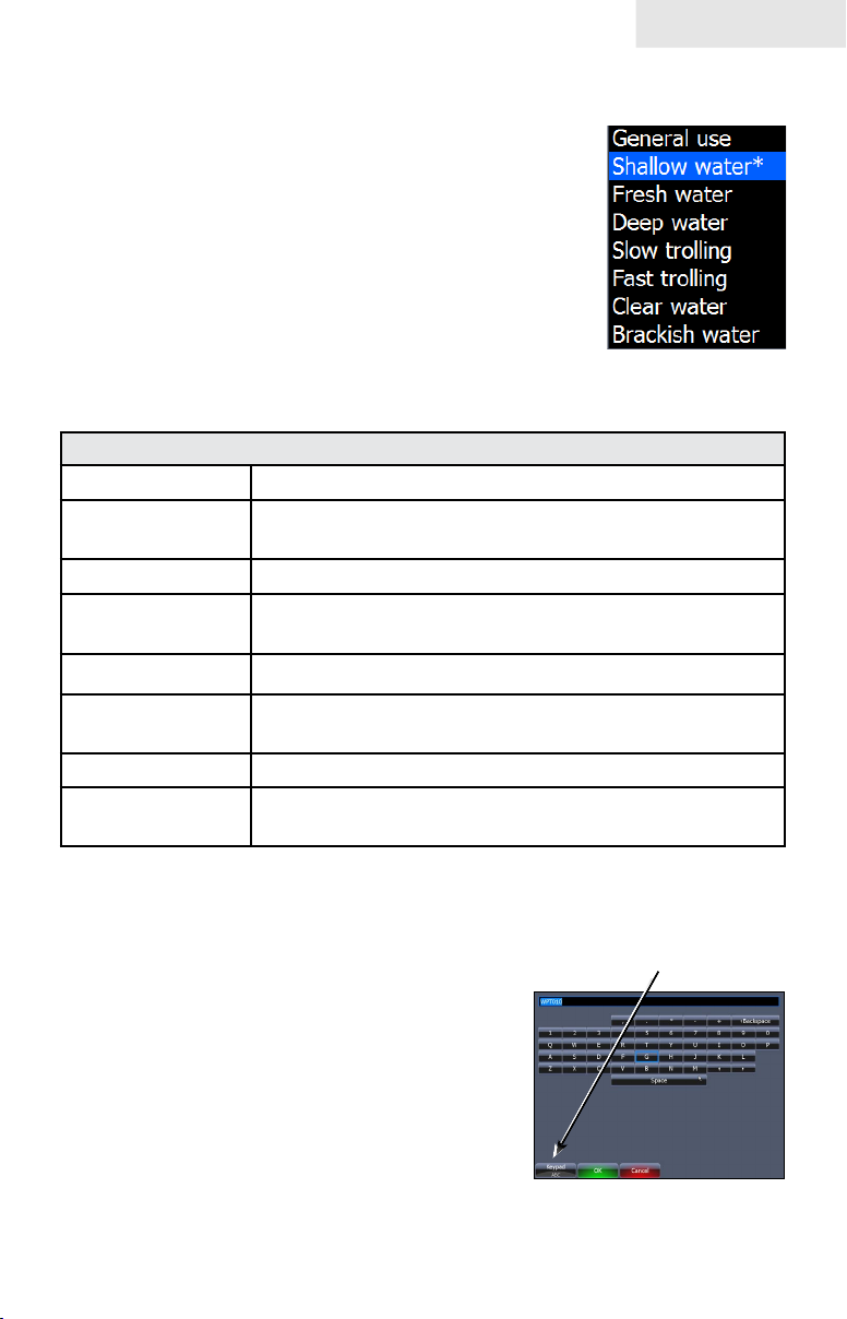
Selecting a Fishing Mode
Fishing modes enhance the performance of your unit by
providing preset packages of sonar settings geared to specic
shing conditions.
To select a shing mode:
Press 1. MENU twice.
Select 2. Sonar and press ENTER.
Highlight 3. Fishing Mode and press ENTER.
Select the desired shing mode and press 4.
ENTER.
Fishing Mode Options
General Use Bottom brown/blue background; 50% ping speed
Shallow Water
Fresh Water Bottom brown/white background; 50% ping speed
Deep Water
Slow Trolling Bottom brown/white background; 50% ping speed
Fast Trolling
Clear Water Bottom brown/white background; 50% ping speed
Brackish Water
Bottom brown/white background; best suited for
depths less than 100 feet
Deep Blue; 50% ping speed; 50kHz is primary
transducer frequency
Bottom brown/white background; slightly lower chart
speed
Bottom brown/blue background; higher ASP; slightly
lower chart speed
Entering Letters in Text Boxes
This unit has some features and functions that may
require you to enter data in a text box.
To enter data in a text box:
Highlight the text box and press 1. ENTER.
A keyboard will appear on the screen.
Use the keypad to highlight the rst 2.
character and press ENTER. Repeat
this step until all characters have been
entered.
Highlight 3. OK and press ENTER.
9
Keypad button controls
uppercase & lowercase
Keyboard window
Page 12
Getting Started
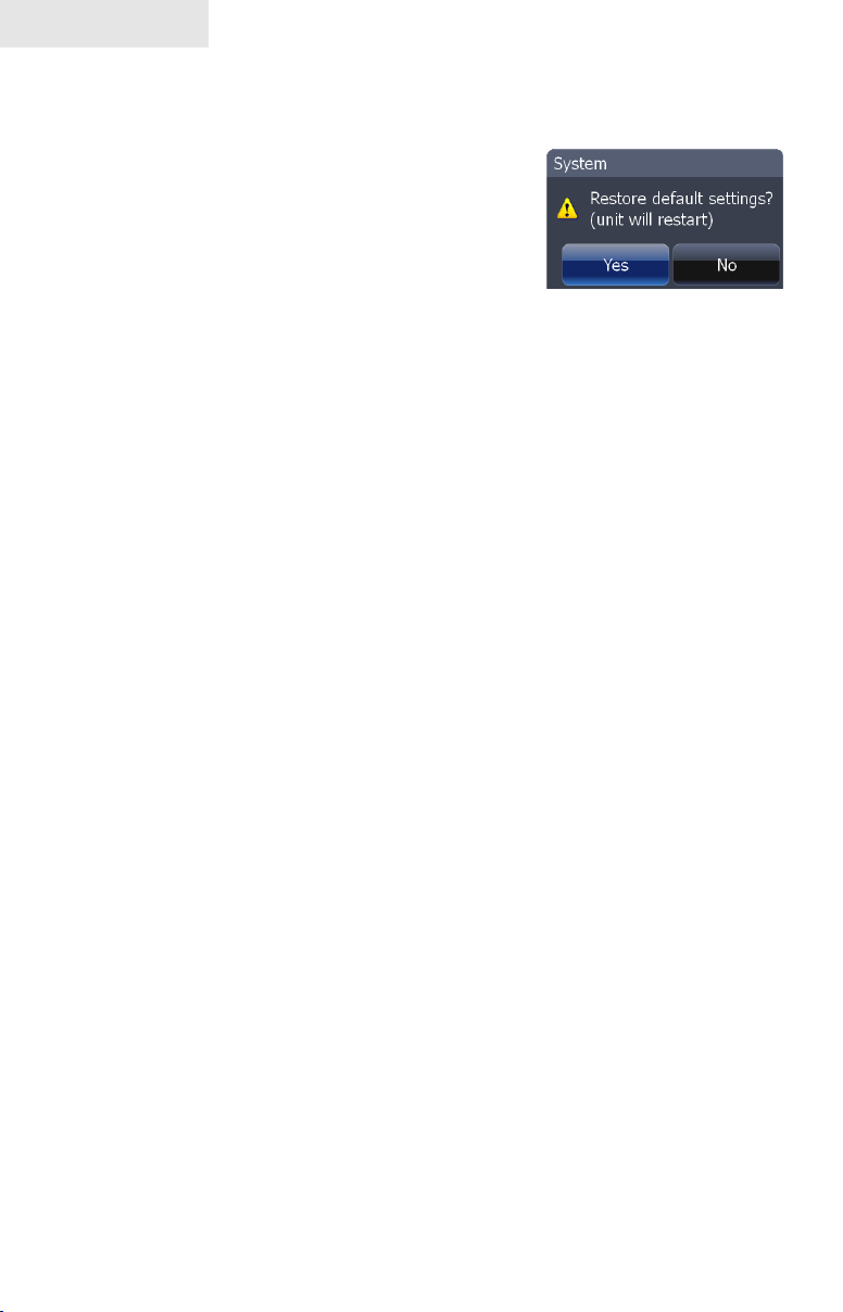
Restore Defaults
The Restore Defaults command switches the unit back to the settings it had when
you purchased it (default settings),
To Restore Defaults:
Press 1. MENU twice.
Select 2. System and press ENTER.
Highlight3. Restore Defaults and press ENTER. A conrmation message
will appear.
Select 4. Yes and press ENTER.
10
Page 13
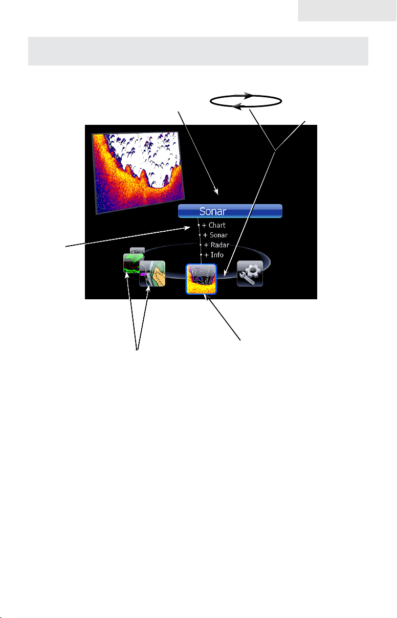
Pages
With Sonar selected, unit will
display a full sonar screen
Combo
display
options
allows you
to display a
split screen
Pages
Page icons
rotate around
the circular
Pages
menu
Sonar icon rotated to center of
Page Icons
page; has blue border indicating
it is the selected page option
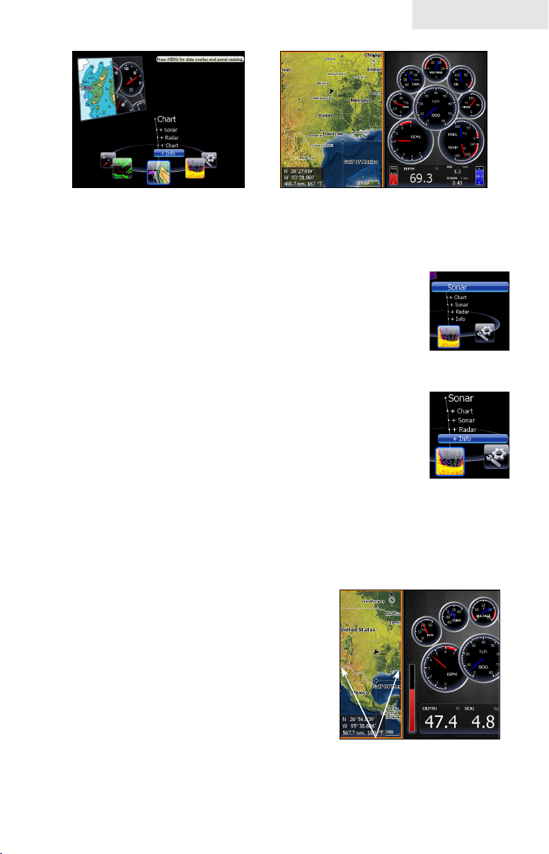
Pages Screen
Consists of four page icons that scroll horizontally around the Pages menu. To view the pages screen,
press the PAGES key.
Selecting Pages
Pressing the keypad left or right will move the page icons around the menu. To select a page, move
the desired page icon to the center of the screen.
When selected, the page name will be highlighted in blue at the top of a list of combo display options.
Its icon, will be framed by a blue border below the list. To display the page, press ENTER.
11
Page 14
Pages
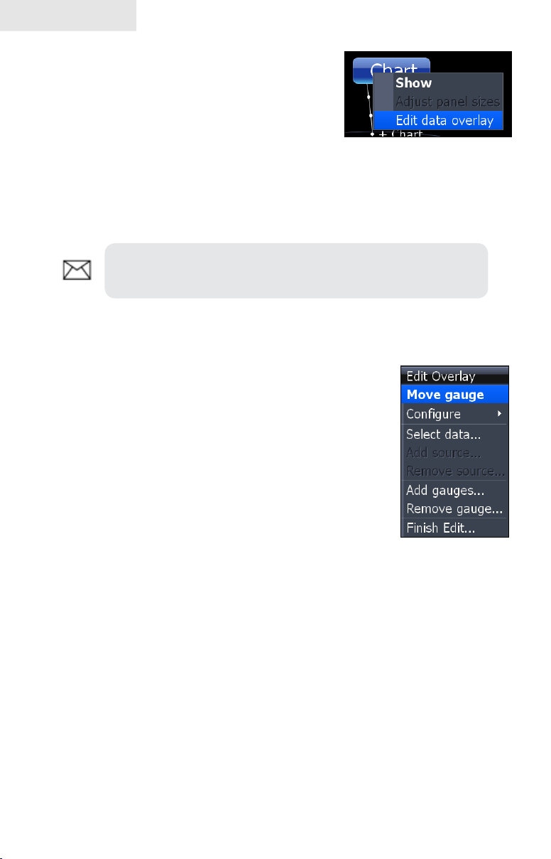
Data Overlay
Data overlay is information you can display on top
of the page screen, allowing you to customize each
page with desired data.
Data Overlay menu
Every page option has its own Data Overlay menu. The menu allows you to edit,
add or remove overlay data from the display. To access Data Overlay menu, select
a page option and press MENU.
NOTE: Adjusting Panel Sizes is covered later in this section in
the Displaying Combo Pages segment.
Edit Overlay menu
Accesses data overlay options for all the unit’s page screens.
To access Edit Data Overlay menu:
1. Select Edit Data overlay from the Data Overlay
menu and press ENTER.
Press 2. MENU. The Edit Overlay menu will appear
with Add Gauge selected.
12
Edit Overlay menu
Page 15
Pages
Edit Mode
When a gauge is added to the display it will be shown in edit mode. Analog and
bar gauges are shaded in blue when they are in Edit Mode. Digital Gauges will be
shown with a blue border.
Analog gauge in edit
mode
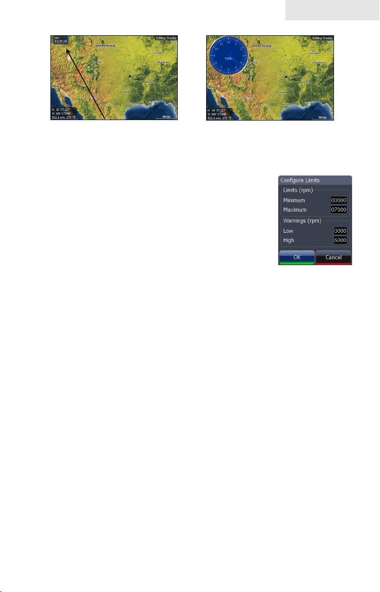
Move or Placing a Gauge
The Move gauge command allows you to move data overlay to any position on the
screen. When you use the Place gauge command, the gauge will be locked in its
current position.
To move or place a gauge:
Press the 1. ENTER key when the gauge is in Edit
mode. Four directional arrows will appear when
the gauge can be moved.
Use the keypad to move the gauge to a desired 2.
location on the screen.
Press 3. ENTER to place the gauge.
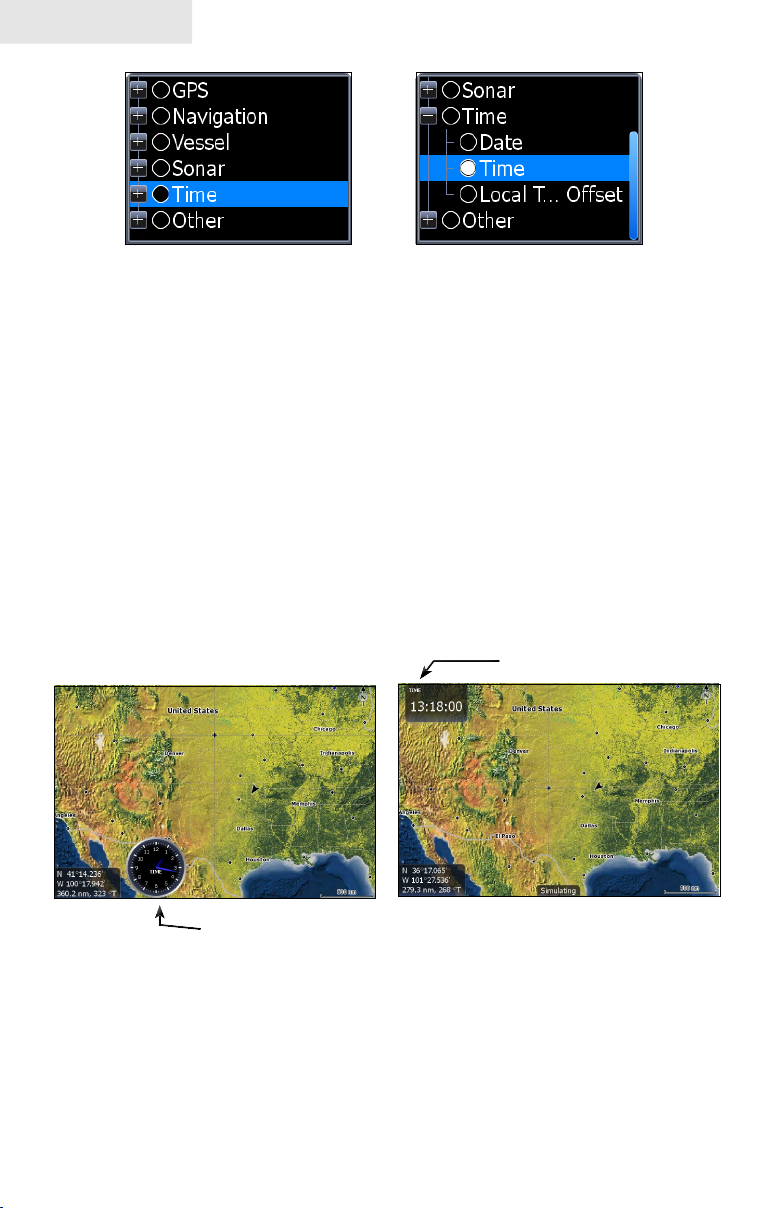
Select Data
Used to select data that will be shown on the data overlay display. When selecting
data you rst will open a main data category and then choose data to be displayed
from the a data subcategory.
Digital gauge in edit mode
13
Page 16
Pages
Select data menu
Time subcategory
To select data overlay:
1. Press the Select data softkey. The Select Data menu will appear.
Use the keypad to select the desired category and press 2. ENTER.
A list of subcategories will appear.
Select the desired subcategory and press 3. ENTER.
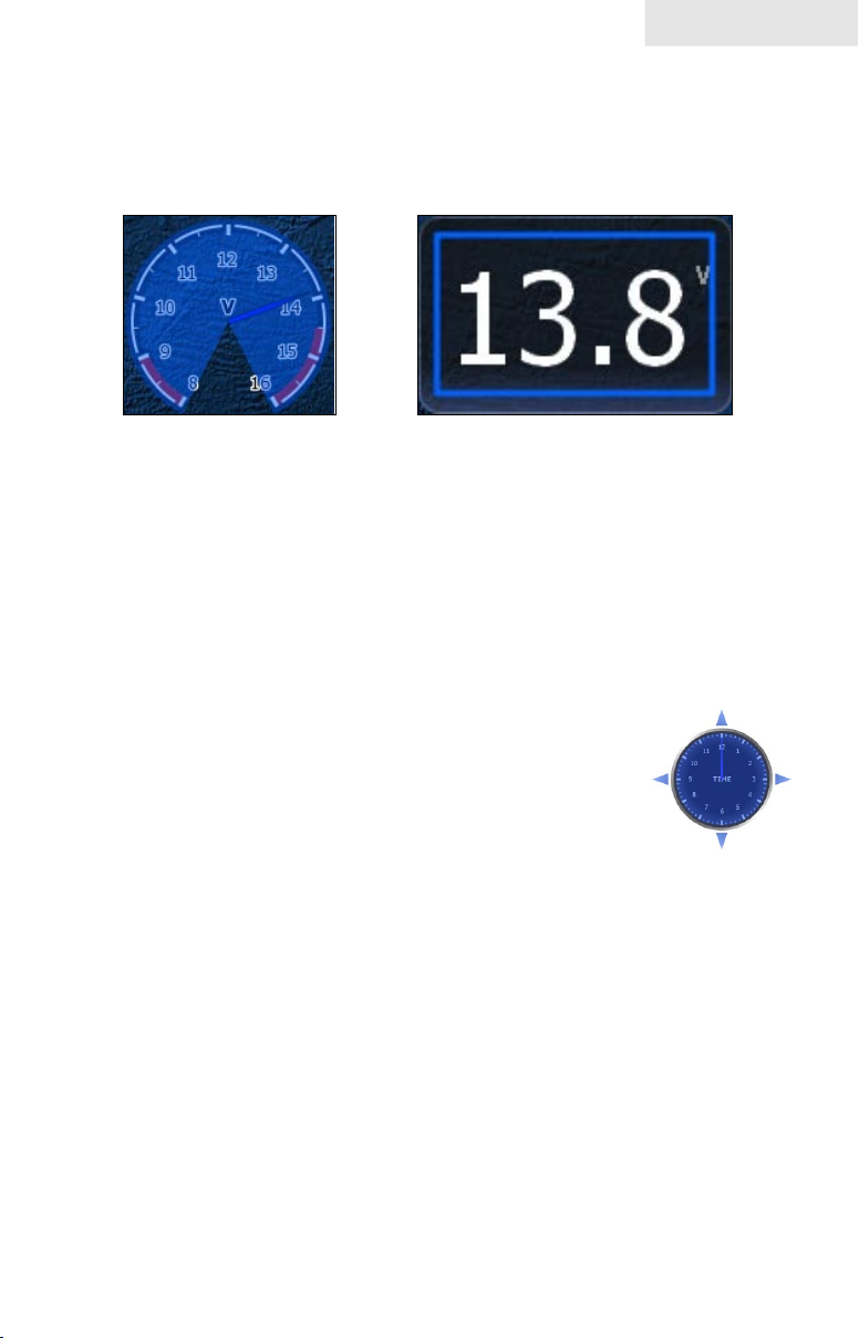
Type
Switches data overlay display between analog, digital and bar gauge formats,
provided the format is appropriate for the selected data type.
To change Type press the Type softkey to toggle between digital and analog gauge
formats.
Time in digital format
Time in analog format
Size
Selects the size of the data overlay display. Data overlay can be displayed in four
sizes.
With the gauge in edit mode (shaded in blue) press the ZOOM OUT key to increase
overlay size; press the ZOOM IN key to decrease overlay size.
14
Page 17
Pages
Small digital gauge
Large analog gauge
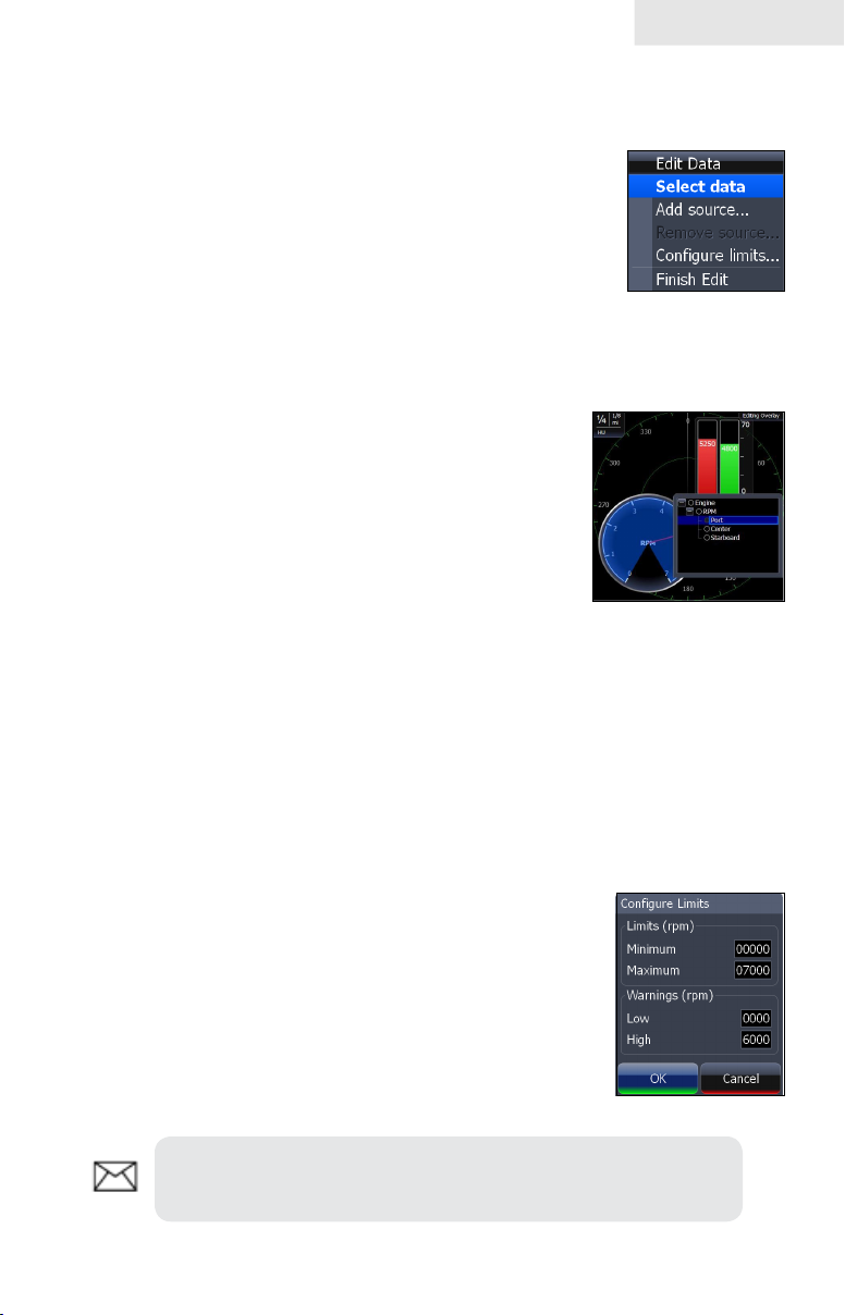
Limits
Controls the number scale used on data overlay gauges and
selects warning thresholds. Changing the limits on an analog
or bar gauge removes unnecessary numbers from the gauge,
making them easier to read. Warnings help you stay within
selected warning thresholds.
Limits are congured by inputting analog or bar gauge limits
in the Limits text boxes — minimum and maximum. Warnings
thresholds are entered in the Low and High text boxes.
To congure limits:
Press the 1. Limits softkey. The Conguration Limits menu will
appear.
Select the Limits or Warnings text box and press 2. ENTER.
Use the keypad to enter the desired threshold.3.
Select 4. OK and press ENTER.
To save changes:
Conguration
Limits menu
Press 1. MENU and highlight Save.
Press 2. ENTER.
15
Page 18
Pages
Conguration menu
Allows you to Add/Remove sources and adjust Bezel, Caption
and Invert Text Settings. Other conguration menu options are
covered previously in the section.
To access the Conguration menu, highlight Conguration on
the Edit Overlay menu and press ENTER.
Conguration Settings
Bezel
Caption Allows you to add/remove data label from gauge
Invert Text Changes appearance of data overlay text
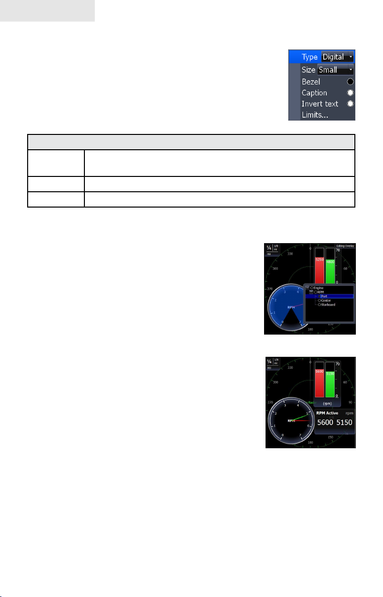
Add Source
Displays the same type of data from different sources on
the same analog gauge.
If, for example, you have multiple engines, you could
select port engine RPM as your data type and then display
starboard engine RPM using the Add source command.
Adds a bezel to the data overlay gauge, making it easier to
see against certain backgrounds
Both data sources could be displayed simultaneously on
an analog gauge with two needles; one dedicated to each
source.
To use Add Source:
Select 1. Add Source from the Edit Overlay menu
and press ENTER. The Add source menu will
appear.
Highlight a category a press 2. ENTER. A list of
subcategories will appear.
Select the desired subcategory and press 3.
ENTER.
To remove add source data:
Highlight1. Remove source from the Edit Overlay menu and press
ENTER. A list of sources will appear.
Select the source you want to remove and press 2. ENTER.
16
Add Source menu
Analog gauge
showing RPM from
two engines.
Page 19
Pages
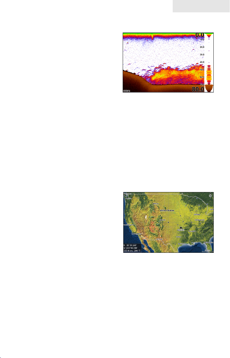
Sonar Page
Displays the water column moving from
right to left on your unit’s screen. On the
right side of the screen, the Amplitude
Scope bar previews echoes about to appear
on the display.
The sonar page has three splitscreen view
settings and 14 color palette settings. Sonar
display options are covered in more detail
in the Sonar Operation section.
On the Sonar Page you can:
Move the cursor to any location on the screen to get a depth reading•
Show sh echoes as sh symbols with sh depths•
Adjust Range to view only desired portion of the water column •
To access the Sonar Page, use the keypad to highlight Sonar on the Pages menu and
press ENTER.
Chart Page
Consists of a Map that moves in real time
as you move. By default, the map is shown
from a birds-eye view with North at the top
of the screen.
This page has three map orientation options
(North Up, Track Up & Course Up) and
two ways to view the map: 2D and Shaded
Relief (only available on select models).
The cursor is used to scroll the map, select
objects and nd the distance between objects. The Chart page is covered in more
detail in the Chart Operation section.
On the Chart Page you can:
Save Waypoints•
Find points of interest (POI)•
Navigate routes; navigate to cursor and waypoints•
To access the Chart page, use the keypad to highlight Chart on the Pages menu and
press ENTER to access the Chart Page.
17
Page 20
Pages
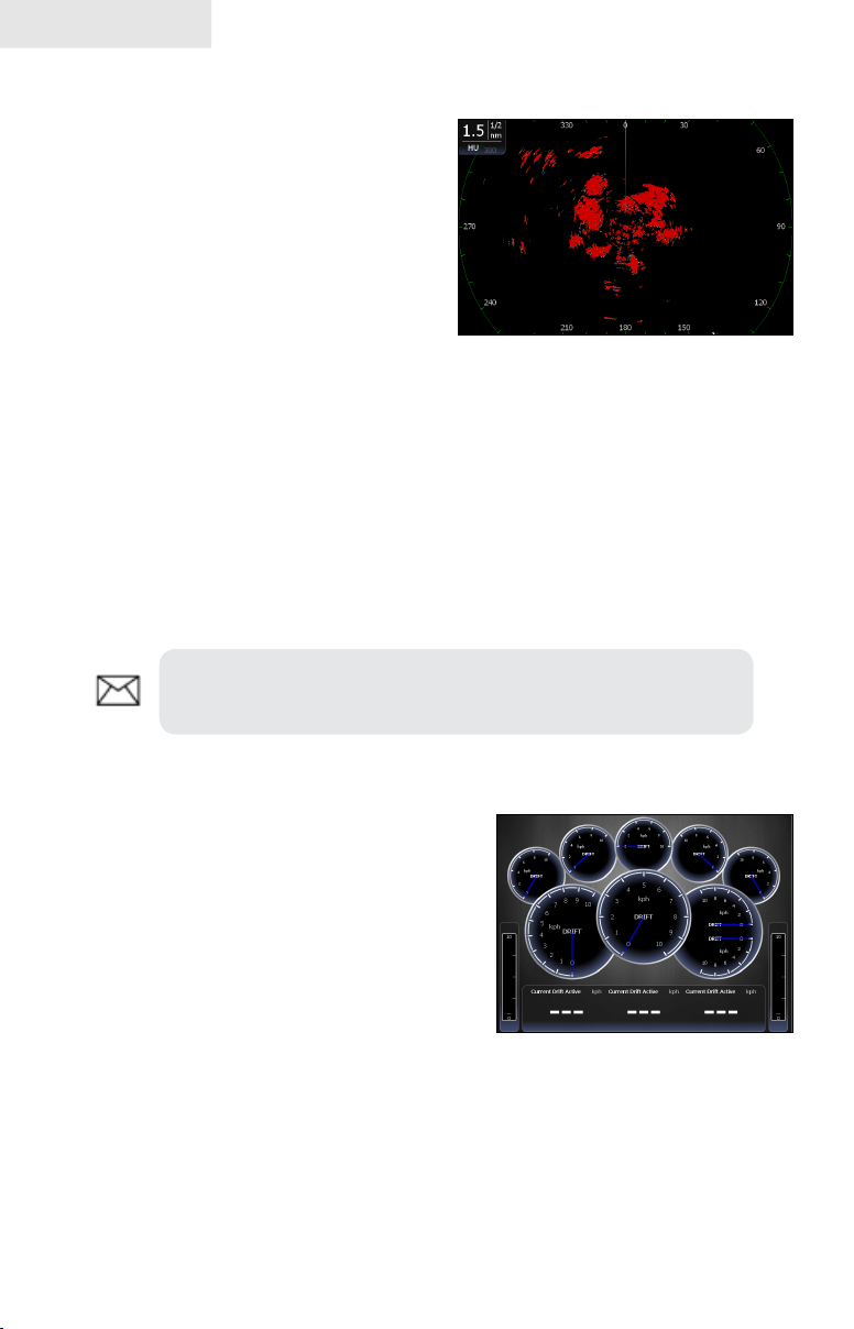
Radar Page
Displays the PPI (Position Plan Indicator)
screen, Range Rings and the cursor.
The PPI can be shifted to show more of a
desired portion of the screen (Look Ahead,
Center & Offset) and the color palette
can be changed to show returns in white,
yellow, black or green. The radar page
is covered in more detail in the Radar
Operation section.
On the Radar Page you can:
Overlay compass data, range rings and EBL/VRMs on display•
Choose screen orientation from Head Up, Course Up & North Up•
Make radar targets more visible via Target Expansion•
Use the keypad to highlight Radar on the page screen and press ENTER to access
the Radar Page.
NOTE: You will only be able to see the Radar page if your unit
is connected to a radar.
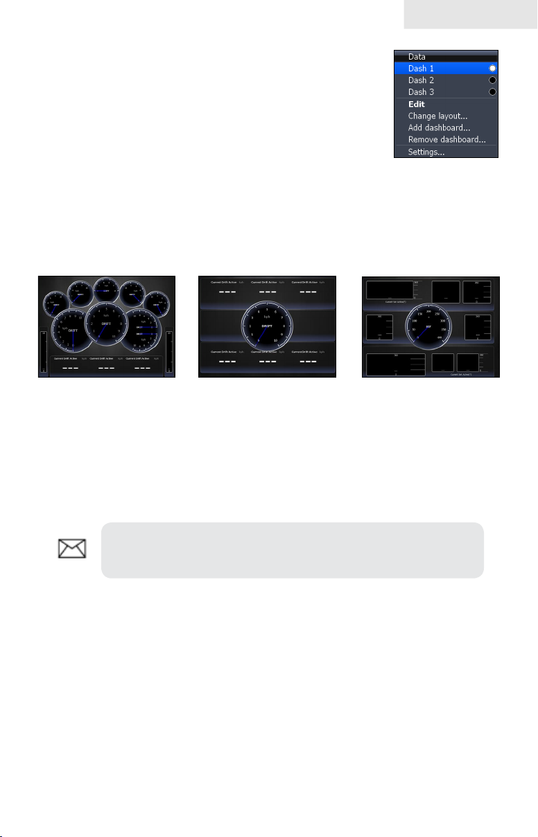
Info Page
Consists of multiple gauges — Analog, Digital
and Bar — that can be customized to display
selected data. Customizing the info page allows
you to monitor several types of desired data at
the same time.
On the Info Page you can:
Select data to be displayed in analog gauge or digital formats•
Change the page layout using one of three templates•
Select the range (scale) of analog gauges •
To access the Info Page, use the keypad to select Info on the pages screen and press
ENTER.
18
Page 21
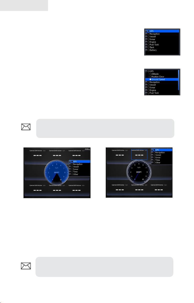
Data menu
Controls Info page data, page layout and data display format
selection. To access the Data menu, press MENU while on the
Info page.
Pages
Dash 1, Dash 2 and Dash 3
Data menu
Info Page dashboard templates that vary in page layout and in the
number of gauges supported. The templates save you time by allowing you to use the
Info page without having to manually set up a gauge layout.
Gauge Layout Templates
General Engine
Layout
Digital Layout
Bar Layout
You can change the gauge layout of Dash 1 (General Engine Layout), Dash 2 (Digital
Layout) and Dash 3 (Bar Layout) templates using the change layout command. To
select a dashboard template, highlight the desired template on the Data menu and
press ENTER.
NOTE: You can toggle through the dashboard templates on the
screen by pressing the keypad left/right.
Edit
Used to select information displayed on the Info page. To switch the screen to Edit
Mode, select Edit from the Data menu and press ENTER. The active gauge will be
shaded in blue (analog) or surrounded by a blue border (digital and bar).
19
Page 22
Pages
To edit gauge display:
Use the keypad to select the gauge you want to 1.
edit and press ENTER. The Select Data menu
will appear.
Use the keypad to select a data category and press 2.
ENTER. A list of subcategories will appear.
Select the desired subcategory and press 3.
ENTER.
Press 4. MENU. The Edit Data menu will appear.
Highlight 5. Finish Edit and press ENTER. The
Finish Edit Data menu will appear.
Highlight the 6. Save button and press ENTER.
NOTE: Press ENTER or EXIT to switch gauges into Edit Mode
GPS category
Ground Speed
subcategory
to Normal Mode.
Editing data on an analog
gauge
Editing data on a digital gauge
Edit Data menu
Changes Info Page gauge data, allowing you to display desired data on analog ,
digital and bar gauges. It also controls gauge limits.
To access the Edit Data menu, switch the screen to Edit mode and press MENU.
NOTE: Select Data, Add Source and Congure Limits are
described in more detail in the previous Data Overlay segment.
20
Page 23
To select data:
Highlight 1. Select Data from the Edit Data menu and press ENTER.
The Select Data menu will appear.
2. Use the keypad to select the desired category
and press ENTER. A list of subcategories will
appear.
Select the desired subcategory and press 3.
ENTER.
To add source:
Select1. Add Source from the Edit Data menu
and press ENTER.
Use the keypad to select the desired category 2.
and press ENTER. A list of subcategories will
appear.
Select the desired subcategory and press 3.
ENTER.
Pages
To remove a source:
Highlight 1. Remove Source from the Edit Data menu and press ENTER.
The Remove data-source window will appear.
Select the source you want to remove and press 2. ENTER.
To Congure Limits:
Highlight 1. Congure Limits on the Edit Data menu
and press ENTER. The Congure Limits menu
will appear.
Select the desired text box and press 2. ENTER.
Use the keypad to enter the desired limit or 3.
warning threshold.
Select 4. OK and press ENTER.
NOTE: The Limits portion of the Congure Limits menu will
only be shown when conguring analog gauge limits.
21
Page 24
Pages
To Finish Editing:
Select 1. Finish Edit from the Edit Data menu and press ENTER.
A conrmation message will appear.
Select 2. Save and press ENTER.
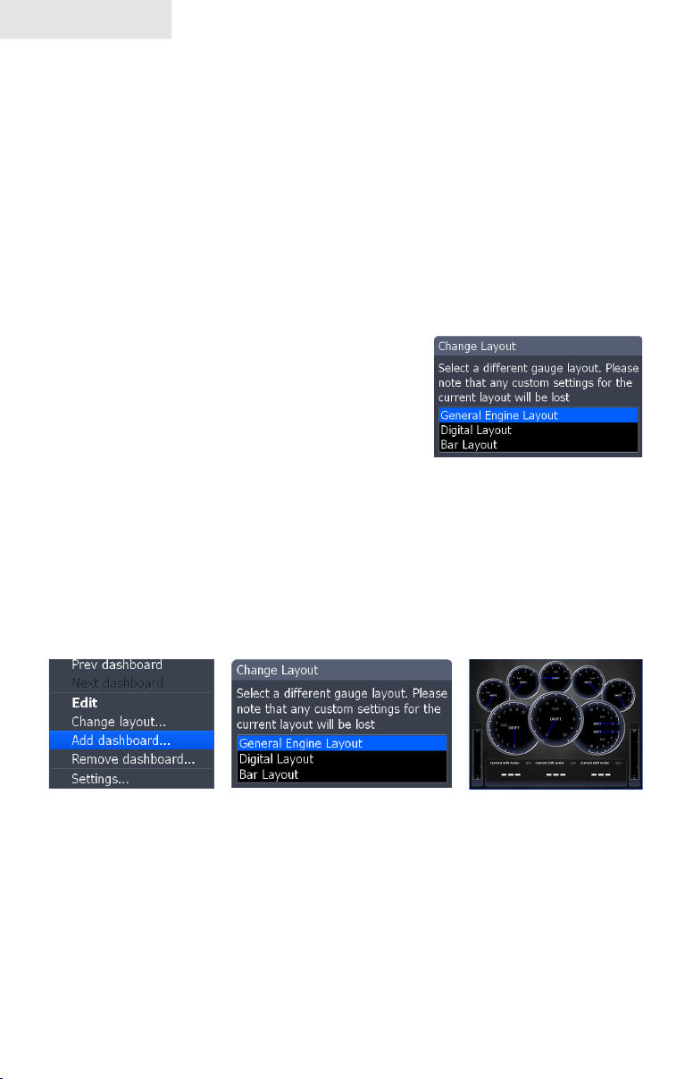
Change Layout
Controls the gauge layout of dashboard templates and customized dashboards. That
allows you to select a desired gauge layout template for all dashboards.
To change layout:
Highlight the desired dashboard and 1.
press ENTER.
Select 2. Change Layout from the Data
menu and press ENTER.
Use the keypad to choose a gauge 3.
layout template and press ENTER.
Add Dashboard
Allows you to customize and save multiple dashboard templates. Desired data can
be added to the gauges on each dashboard, allowing you to create custom dashboards
for a variety of shing conditions. You can even use the same gauge layout template
for each dashboard.
When you have created all desired dashboards, press the keypad left/right to toggle
through your dashboards.
To add a dashboard:
Select 1. Add Dashboard from the Data menu and press ENTER. The
Change Layout menu will appear.
Select the desired gauge layout and press 2. ENTER. Refer to the
previous Edit segment to customize the dashboard.
22
Page 25
Pages
To remove dashboards:
Select the number of the dashboard you want to 1.
delete from the numerical dashboard list.
Highlight 2. Remove Dashboard and press ENTER.
A conrmation message will appear.
Select 3. Delete and press ENTER.
Settings
Opens the Settings menu. Settings information is covered in detail in the Settings
menu section.
Numerical
dashboard list
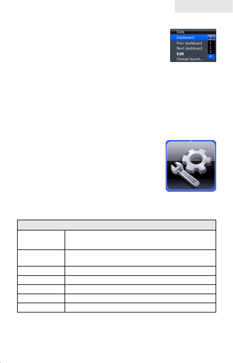
Utilities
Allows you to set alarms, view sonar logs and access other
system settings.
To access Utilities:
Use the keypad to center the utilities icon on 1.
the screen.
Scroll down the list of utilities until the desired 2.
option is highlighted.
Press 3. ENTER.
Utilities Icon
Utilities
Waypoints,
Routes/Trails
Find
Alarms Access alarm history, status and change settings
Vessels View status and messages from vessels in the area
Sun/Moon Displays time when sun and moon will rise/set
Trip Calculator Keeps running tally/total of engine hours
Files Access, copy and delete data les and sonar logs
Access Waypoint, Route and Trails screen; covered in
the Chart Operation Section
Search for POIs, Vessels, Coordinates, Trails, Waypoints
and Routes; covered in Chart Operation Section
23
Page 26
Pages
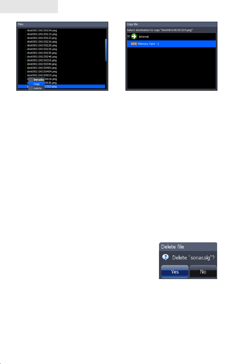
Copying a screenshot
To copy data les/sonar logs:
1. Highlight Files from the Utilities menu and press ENTER.
Select the desired File category and press the keypad to the right. A 2.
list of subcategories will appear.
Select a subcategory and press the keypad to the right. Highlight 3.
the desired data le/sonar log.
Press 4. MENU. Highlight Copy and press ENTER. The Copy File
screen will appear.
Select a place to copy the le, like an MMC card. Press 5. ENTER.
To delete data les/sonar logs:
Highlight 1. Files from the Utilities menu and press ENTER.
Select the desired File category and press 2. ENTER. A list of
subcategories will appear.
Select a subcategory and press 3. ENTER.
Highlight the desired data le/sonar log.
Copy and Delete buttons will appear at the
bottom of the screen.
Copy File screen
Select the 4. Delete button and press ENTER. A conrmation message
will appear.
Select 5. Yes and press ENTER.
24
Page 27
Pages
Info selected as combo
display option
GPS/Info combo page
Displaying Combo Pages
You can display multiple pages at the same time by scrolling the
desired page’s icon to the center of the screen and then choosing a
secondary page from the list of combo page display options.
To display a combo page:
Use the keypad to select the rst page for the combo 1.
display. This is the primary page, which will be
displayed in the left panel.
Select another page from the primary page’s combo 2.
display list. This is the secondary page. It will be
displayed in the right panel.
Press 3. ENTER. The selected combo page will be
displayed.
Selecting an Active Page
When combo pages are displayed only one panel
can be active at a time. The panel outlined with
an orange border is the active page. You will only
be able to access the context menu of the active
panel. Pressing the MENU key will open the active
panel’s context menu.
Primary page
Secondary
page
To switch the active setting to the other panel, hold
down the PAGES key for 1 second.
25
Chart panel is active as
shown by the orange border
Page 28
Pages
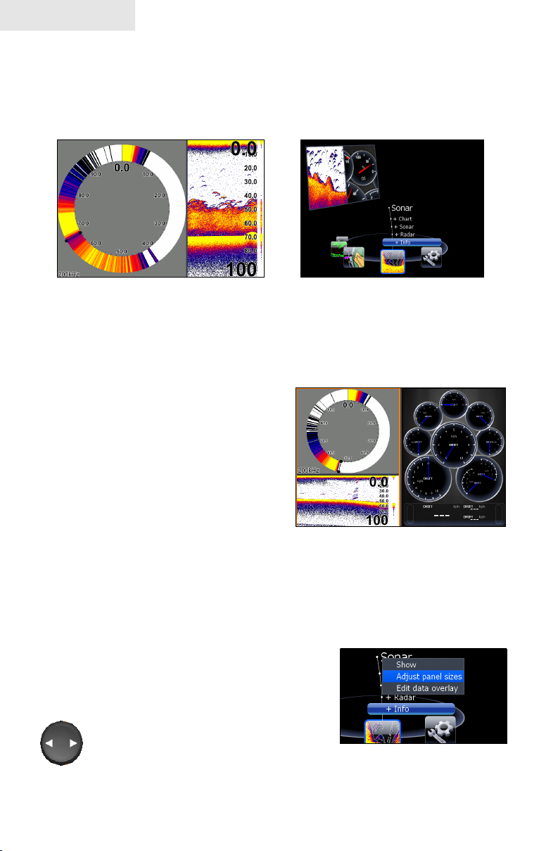
Displaying Multiple Panels
Multiple panels can be displayed by setting up a combo display using a page that
supports the Split feature. By displaying multiple panels, you can view more
information on the screen at one time.
Step 1: Select sonar split screen
Step 2: Choose page from
combo display options list
To display multiple panels:
Select a Split view for the sonar page. (Accessing the Split feature 1.
is covered in detail in the Using
your Sonar section.)
Press the 2. PAGES key and use
the keypad to center the Sonar
icon on the screen.
Use the keypad to select Info 3.
Page from the combo page
display list. Press ENTER. The
combo page will be displayed
with the Sonar split view on the
Flasher, normal sonar and the
info page shown on a multi-panel
left; the Info page on the right.
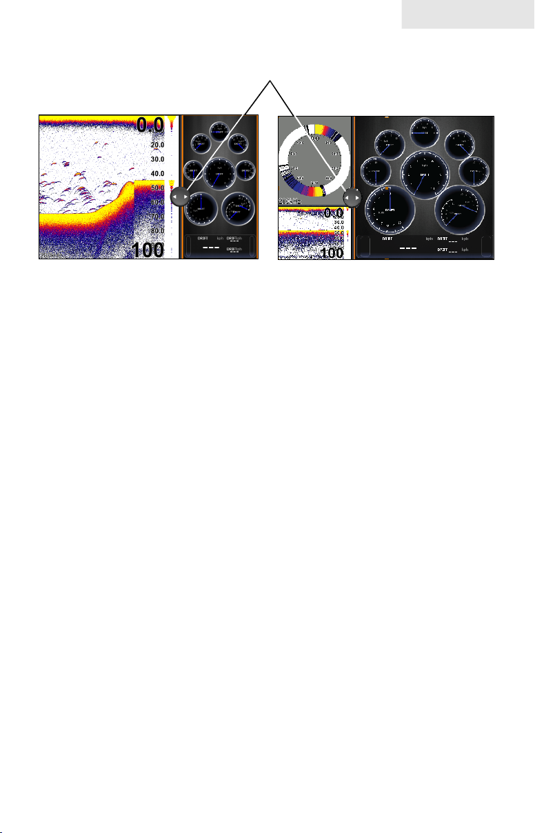
Adjust Panel Sizes
Controls the size of panels when combo pages or
multi-panels displays are in use. Adjusting the size
of the panels, allows you to emphasize the panel
you want to see more clearly.
Panels can only be adjusted left/right, so
the panels on the side with the split view
can not be adjusted vertically.
display.
Adjust panel sizes selected
on the Data Overlay menu
26
Page 29
Pages
Moving panel cursor left/right will change the size
of each panel
Adjusting panels on combo page Adjusting panels on multi-panel
display
To adjust panel sizes:
With the combo page or multi-panel display on the screen, press 1.
the PAGES key.
Press 2. MENU. Highlight Adjust Panel Sizes from the Data Overlay
menu and press ENTER.
Press the keypad left/right to adjust the panels to a desired size and 3.
press ENTER.
27
Page 30

Pages
Blank page
28
Page 31

Sonar Operation
Sonar
Water column
Cursor depth
Brush
Water depth, water
temp and cursor
coordinates
Surface clutter
Colorline
Blue sonar history bar; reviews
recent sonar history
Temperature Graph
Fish Arches
Cursor
Range
scale
Depth
Line
Amplitude Scope
— shows amplitude
of real-time sonar
echoes
To access the Sonar Page:
Press the 1. PAGES key.
Use the keypad to select 2. Sonar and press ENTER.
Cursor
Viewing Sonar History
You can review your recent sonar history by moving the cursor to the left until
the screen starts to move in reverse.
To resume normal sonar scrolling, move
the cursor to the right until the blue sonar
history bar at the bottom of the screen is
all the way to the right. Press EXIT to
remove the cursor from the screen.
Blue sonar history bar
29
Page 32

Sonar
Sonar Menu
Accesses features ranging from Auto Sensitivity and
Depth Range to Frequency and Stop Sonar.
From the Sonar Page, press MENU to access the Sonar
Menu.
Sensitivity
Controls the level of detail shown on the display. Increasing
Sensitivity will show more detail on the screen; decreasing Sensitivity displays less.
Too much detail will clutter the screen. Conversely, desired echoes may not be
displayed if Sensitivity is set too low.
Sensitivity set to 60 percent
NOTE: By default, Sensitivity is set to auto mode. You may
have to turn off Auto Sensitivity to set sensitivity to a desired
level. Auto Sensitivity is covered in more detail later in this
section.
Sensitivity set to 80 percent
Sonar Menu
Auto Sensitivity
Keeps sensitivity at a level that works well under
most conditions, reducing the need for adjustments.
You can make minor changes to sensitivity with Auto
Sensitivity turned on, but you will have to turn it off
to make signicant adjustments.
Auto Sensitivity can be turned on/off by selecting Auto Sensitivity from the Sonar
menu and pressing ENTER.
30
Page 33

Sonar
Colorline
Distinguishes strong sonar echoes from
weak sonar echoes. That makes it easier
Wide yellow hard
sonar return
Reddish-blue soft
sonar returns
for you to distinguish sh or structure from the
bottom.
A hard return will be shown as a wide, bright
yellow line, whereas a soft return will be a
narrow reddish-blue line.
Range
Used to select the section of the water column — from surface to bottom — shown
on the display. When there is a portion of the water
Range set to 60 feet
column you want to focus on, select a range from
the Depth Range menu that includes the desired
area.
The values on the Range menu determine the depth
shown on the display. If you selected 20m from the
range menu the unit will display 0-20m of the water
column, regardless of the water depth. There are
21 depth ranges, including automatic and custom
settings. The automatic setting will set the range
from the water surface to water depth.
Frequency
This unit supports three transducer frequencies; two of which are supported by your
transducer. 200 kHz has the highest sensitivity and best target discrimination in
shallower water; 83 kHz offers a wider cone angle for greater water coverage and
50 kHz provides the best depth penetration. You can view both available frequencies
at the same time by setting up a sonar split screen.
Split
Adjusts the conguration of sonar page display using one of four options: No Split,
Zoom, Bottom Lock and Flasher.
Zoom display Bottom Lock Flasher Display
31
Page 34

Sonar
No Split • — displays full sonar screen
• Zoom — splits display with a zoomed-in panel on the left (press
ZOOM key to increase zoom) and a normal sonar view on the right
• Bottom Lock — splits the display with a 2X zoom on the left; a normal
sonar view on the right. Keeps the bottom on the screen at all times.
• Flasher — splits the display with a asher-style sonar on the left; a
normal sonar view on the right
Stop Sonar
Pauses the sonar chart, allowing you to get a closer look at sonar echoes.
Adjust
Sensitivity and Colorline can also be adjusted from the Sonar menu by using the
Adjust command.
To Adjust Sensitivity and Colorline:
Highlight 1. Adjust on the Sonar menu
and press ENTER. Press the keypad
up/down to select the Sensitivity or
Colorline scrollbar.
Press the keypad left/right to make 2.
adjustments.
Press 3. EXIT.
32
Page 35

Custom — Upper and Lower Limits
Controls not only the depth range (lower limit), but
also lets you choose the upper limit. So, instead of
a selecting a range that includes the water surface,
you can choose upper and lower limits anywhere
along the water column. The Upper and Lower
limit must be at least 2 meters apart.
To set Upper and Lower Limits:
Select 1. Range and press ENTER.
Highlight 2. Custom and press ENTER.
The Upper and Lower Limit window will appear.
Select the Upper or Lower Limit dialog box. Press 3. ENTER. The
numerical keypad will appear.
Use the keypad to enter the desired value in the corresponding 4.
upper or lower limit dialog box. Press ENTER.
Repeat Steps 3 and 4 to input the desired limit in the other dialog 5.
box.
Sonar
Upper limit is 15 feet; lower
limit is 65 feet
Ping Speed
Ping Speed controls the rate the transducer uses to
send sonar waves into the water. A higher ping speed
will yield the best results when you are moving across
the water at a high rate of speed or shing from a dock. The reverberation of too
much ping speed can cause interference on the screen.
When using two units on your boat, lowering the ping speed of one of the units will
prevent interference (cross-talk) caused by one transducer detecting pings from the
other transducer. The default setting is suitable for most conditions. Highlight Ping
Speed on the Sonar menu and press the keypad left/right to make adjustments.
Sonar Options
Adjusts display settings and the conguration of the
display. The Sonar Options menu allows you to split the
screen between two sonar views, change the color of
the display, use Fish ID and add graphical elements to
screen that will enhance your sonar experience.
To access the Sonar Options menu, select Sonar Options
from the sonar menu and press ENTER.
33
Page 36

Sonar
To select a Split option:
From the Sonar Options menu, 1.
highlight Split and press ENTER.
The Split menu will appear.
Use the keypad to select the desired 2.
option and press ENTER.
Palette
Sonar display color templates with varying degrees of color
and brightness. On the Palette menu, you can select a sonar
display template suited for your shing conditions from 14
palette options.
A bottom brown
palette clearly
separates sh
and structure from
the bottom
To select a Palette:
From the Sonar Options menu, highlight 1. Palette and press ENTER.
Use the keypad to select the desired palette and press 2. ENTER.
Palette menu
34
Page 37

Temperature Graph
Uses a red line graph with digital display at
the top of the screen to illustrate changes in
Temperature. The Temperature graph makes it
easier to recognize temperature trends.
To turn the Temperature Graph on/off, highlight
Temperature Graph on the Sonar Options menu
and press ENTER.
Depth Line
Displays a dark line over the bottom surface,
making it easier to distinguish the bottom from
sh, trees and other objects.
To turn on/off the Depth Line, select Depth Line
and press ENTER.
Amplitude Scope
Allows you to see the amplitude of real-time echoes as they appear
on the display. The Amplitude Scope displays live returns even when
you are viewing your sonar history. To turn off the Scope, highlight
Amplitude scope on the Sonar Options menu and press ENTER.
Sonar
Temperature graph
Depth Line
Amplitude Scope
Zoom Bars
When your unit is in Split Zoom mode, zoom bars show which echoes will be
displayed on the screen when the display is zoomed in to a particular zoom range.
Only echoes shown between the top and bottom of a zoom bar will be displayed at
that selected zoom range.
To turn on/off Zoom Bars, highlight Zoom Bars on the Sonar Options menu and
press ENTER.
NOTE: When the screen is zoomed, you can use the Zoom
Pan feature to scroll up and down the water column. That
allows you to see portions of the water column not visible at
the selected zoom range. When turned on, Zoom Bars will
appear when the Zoom in key is pressed.
35
Page 38

Sonar
Fish ID
Displays sh echoes as sh symbols instead of
sh arches with or without depth. This makes
it easier to recognize sh on the sonar display.
Symbols — places a sh symbol where a
sh is detected.
Depths — places depths above each sh
detected; helps gauge the distance from each
sh symbol to the boat.
Both — turns on both Symbols and Depths.
To select Fish ID option:
Highlight 1. Fish ID and press ENTER.
Use the keypad to select 2. Symbols, Depths or Both and
press ENTER.
Fish Symbols and Depths
Log Sonar Data
Used to save sonar chart data to your unit’s internal memory or to an MMC/SD
card.
To access the Sounder Logging menu, select
Log Sonar Data from the Sonar menu and press
ENTER.
Log Sonar Menu
Filename
Save to
Bytes
Time Remaining
Input the desired name for the sonar log le
Selects location where sonar log will be saved/stored
Controls number of bytes per sounding. More bytes yields
better resolution/shorter logging time; conversely, fewer
bytes produces longer sonar logs/lower resolution
Recording time left until memory storage runs out
36
Page 39

To input lename:
Highlight the Filename text box and 1.
press ENTER. A keyboard will appear
on the screen.
Use the keypad to input the desired 2.
lename.
Sonar
Select 3. OK and press ENTER.
Internal selected on device menu
To select Save to or Bytes per Sounding:
Highlight 1. Save to or Bytes per Sounding from the Sounder Logging
menu and press ENTER.
Use the keypad to select the desired option and press 2. ENTER.
Start Logging
A sonar log is a recording of sonar activity displayed on
the sonar page.
To record a sonar log, highlight the Start Logging button
and press ENTER.
Filename keyboard
Bytes per sounding
menu
When a sonar log is being recorded, a blinking red circle
will be displayed in the upper left-hand corner of the
screen and a logging message will appear periodically
at the bottom of the screen.
37
Logging Indicator blinks
when sonar is being
recorded
Page 40

Sonar
To stop logging:
Select 1. Stop from the Sounder Logging
menu and press ENTER. The Stop
Logging menu will appear.
Highlight the 2. Stop Logging button and
press ENTER.
NOTE: Refer to the Utilities segment of the Pages section for
Stop Logging menu
information on copying and deleting les.
38
Page 41

Chart Operation
Displaying the Chart page
Access the Chart page from the Pages menu.
Chart
To access the Chart
page, press the Pages
key to bring up the Pages
menu. Use the Arrow
keypad to select Chart
and press Enter.
Chart page (2D Chart mode)
Point of Interest (POI)
Cursor coordinates
Current position icon
Waypoint
39
Chart orientation indicator
Cursor
Map scale
Page 42

Chart
The previous image shows some of the different items you will see when viewing
the Chart page:
• Point of Interest (POI): A position on the Chart page represented by
a symbol or character.
Cursor: • Used to view specic areas on the Chart page, select POIs,
create waypoints and measure distances. When the cursor is on-
screen, pressing the Exit key will toggle between the cursor's location
on the Chart page and your actual position. As long as the cursor is
on the Chart page your actual position may not be visible.
• Chart orientation indicator: Indicates the current direction the Chart
page is facing.
• Cursor coordinates: Displays the coordinates of the cursor on the
Chart page.
Waypoint: • An electronic address based on the latitude and longitude
of a selected Chart location.
• Map Scale: Represents the relationship between the distance on
the Chart page and the real distance on the earth's surface.
Current position icon:• Represents your current position.
Find Current Position
Power on the unit and display the Chart page. The current position icon represents
your current position on screen. The icon always points to your heading.
If the current position icon displays a question mark then the unit has not
achieved a satellite lock and is not tracking your current position. When
sufcient satellites are received to determine a position, the icon's move-
ment will correspond with your movement.
Chart menu
Use the Chart menu to adjust settings and enter commands. From this menu you have access to routes, waypoints, info, chart options and screen settings. To open the Chart menu, go to the Chart page and press the MENU key. The following features are listed in the order they appear on the Chart menu, top to bottom:
New Waypoint:• Creates a new waypoint.
New Route: • Creates a new route.
Go to Cursor: • Navigates to the cursor position
on the Chart page.
40
Chart menu
Page 43

Find: • Opens the Find menu. From the Find menu you can search for
items by select categories.
Info: • Shows a list of items close to the cursor.
Measure: • Used to measure the distance between current position
and another point on the Chart page or between two different points.
Overlay: • Toggles radar overlay overlay on or off.
Chart options: • Opens the Chart options submenu which contains
the Map Orientation, Look Ahead, Chart categories and Imagery features.
Map Orientation controls the way the Chart
page moves in relation to your movement. The
Map Orientation settings are North Up, Heading Up and Course Up.
Look Ahead increases the view of your track.
Chart
Chart categories opens the Chart Categories
screen.
Imagery selects between 2D and Shaded Relief
mapping (only available on select models).
Settings: • Opens the Settings menu.
Chart options submenu
Selecting POIs on Chart page with Cursor
To select a Chart page POI:
From the Chart page use the 1.
Arrow keypad to center the
cursor over a POI. A pop-up
box will appear describing the
POI. The POI's coordinates are
displayed in the lower left hand
corner of the Chart page.
41
Page 44

Chart
Waypoints
A waypoint is the latitude and longitude of a specic position on the earth's surface.
You can quickly create a waypoint at your current position or you can create a way-
point at the cursor's position on the Chart page. You also can create a waypoint at
any location by manually entering the position's latitude and longitude.
Waypoints are important because they can be saved in the unit and later used to nd
your way back to a specic location, such as a favorite shing spot or an important
geographical feature. To quickly save a waypoint at the vessel's current position
press the WPT/FIND key.
Create/Delete Waypoint from Chart page
To create a Waypoint at the Cursor's
position on Chart page:
Place the cursor on the Chart 1.
page where you want to set the
waypoint and press ENTER
twice. The New Waypoint
menu will appear.
Select 2. Save from the New
Waypoint menu.
To create a Waypoint at the Vessel's position on Chart page:
Press the 1. MENU key. From the Chart menu select New Waypoint.
When the New Waypoint at Vessel menu appears, select 2. Save.
New Waypoint at Cursor menu
42
Page 45

Chart
To Navigate to a Waypoint from the Waypoints screen:
From the Pages screen select 1. Waypoints, routes, trails, press ENTER.
When the Waypoints screen appears select the waypoint you want to
navigate to from the waypoints list and press MENU. The Waypoints
screen menu will appear. From the Waypoints screen menu select
Go to.
Waypoints screen
To view stored waypoints go to the Waypoints screen in the Utilities page. From the
Waypoints screen you can view and edit stored waypoints.
Waypoint name
Waypoint icon
Waypoint latitude
and longitude.
Time and date the
waypoint was created.
43
Page 46

Chart
Waypoints screen menu
To open the Waypoints screen menu, press
the MENU key from the Waypoints screen.
The following features are listed in the
order they appear in the Waypoints screen
menu, top to bottom:
Edit:• Opens the Edit Waypoint
menu.
New:• Opens the New Waypoint
menu.
Show:• Shows the Waypoint on the Chart page.
Go to:• Select to navigate to the waypoint.
Delete:• Deletes selected waypoint.
• Sort: Controls how waypoints are sorted in the Waypoints screen
list.
Delete All: • Select to delete all waypoints.
Find:• Use to search for waypoints in the Waypoints screen.
Waypoints screen, Search for Waypoint by name
If the waypoint list contains too many waypoints to search through manually, you
can search for a specic waypoint by name.
To Search for Waypoint by Name:
From the Waypoints screen 1.
press the MENU key. The
Waypoints screen menu will
appear.
From the Waypoints screen 2.
menu select Find. A keypad
will appear. Use the keypad to
enter the name of the waypoint
you are searching for and press
OK.
44
Page 47

Chart
Waypoints screen, Sort Waypoints
feature
You can choose how waypoints are sorted in
the Waypoints list by selecting Sort from the
Waypoints screen list menu. Waypoints can be
sorted by Name, Nearest or Icon. By default the
unit stores waypoints by name.
Waypoint Information screen
When a waypoint is saved to the Chart page, you can view detailed information
about that saved waypoint.
To view waypoint information:
Place the cursor over the waypoint 1.
and press the MENU key.
Select 2. Info and press ENTER.
Editing a Waypoint on the Chart page
To Edit a Waypoint from the Chart page:
Place the cursor over the waypoint and press the 1. ENTER key. The
Edit Waypoint menu will appear.
Edit Waypoint menu
The Edit Waypoint menu is used to edit waypoint
settings and coordinates. Use this menu to change
the name, icon, color and description of a waypoint.
Edit Waypoint, More options:
Select More from the Edit Waypoint menu and the following edit options will appear:
Name:• Edit the name of a waypoint.
Position:• Enter a latitude or longitude for a waypoint.
Icon:• Select a different waypoint icon.
• Color: Change waypoint icon color.
45
Page 48

Chart
• Description: Input additional way-
point information.
Display: • Choose how a waypoint will
be displayed on Chart page.
Depth: • Select waypoint depth.
• Alarm Radius: Input distance that
sounds alarm when near a specic
waypoint.
Delete:• This will delete a waypoint.
Save:• Saves your waypoint changes.
Cancel:• Cancels any waypoint changes.
Edit Waypoint name, description, position or depth
To Edit Waypoint name or description:
From the Edit Waypoint menu, select 1.
the Name or Description text box
and press ENTER. The Waypoint
keypad will appear.
Use the keypad to enter the desired 2.
waypoint name and select OK.
To Edit Waypoint position:
From the Edit Waypoint menu select the 1.
latitude or longitude text box and press
ENTER.
Use the Arrow keypad to input the desired 2.
latitude or longitude and select OK.
To Edit Waypoint depth or alarm radius:
From the Edit Waypoint (More) menu select the Depth or Alarm 1.
radius text box and press ENTER. A numerical keypad will appear.
Use the keypad to input the desired depth or alarm radius and press 2.
ENTER.
46
Page 49

Chart
Edit Waypoint icon and color
You can change the default waypoint icon and color from the Edit Waypoint menu.
Edit Icon menu
Use the Edit Icon menu and Edit
Icon Color menu to change the
appearance of icons on the Chart
page.
Icon color palette
Routes
Routes make it easier to plan trips to desired destinations and backtrack to a previous
location. A route is a series of waypoints linked together to mark a course of travel. A
route must have at least two waypoints. The route segment between two waypoints
is called a leg.
The legs of a route are based on straight lines between waypoints. A route gives you
the ability to navigate to several waypoints in an ordered sequence without having
to manually select the next waypoint in the series.
Create Route from Chart page
To create a new route open the Chart menu and select New Route. You can use the
cursor on the Chart page to create a route.
To Create a New Route from the Chart page:
Press the 1. MENU key and select New Route from the Chart menu,
press ENTER.
Move the cursor to the start of the route and press 2. ENTER to set
the rst waypoint. Move the cursor to the next location and press
ENTER to set a second waypoint.
47
Page 50

Chart
Repeat Step 2 until you have set all the desired waypoints along 1.
the route.
Press the 2. MENU key to open the Edit route menu. Select Save and
press ENTER. The route will be saved to the Routes screen.
From the Routes screen highlight the route and select 3. Start. The
Start Route message box will appear, select Forward.
48
Page 51
Chart
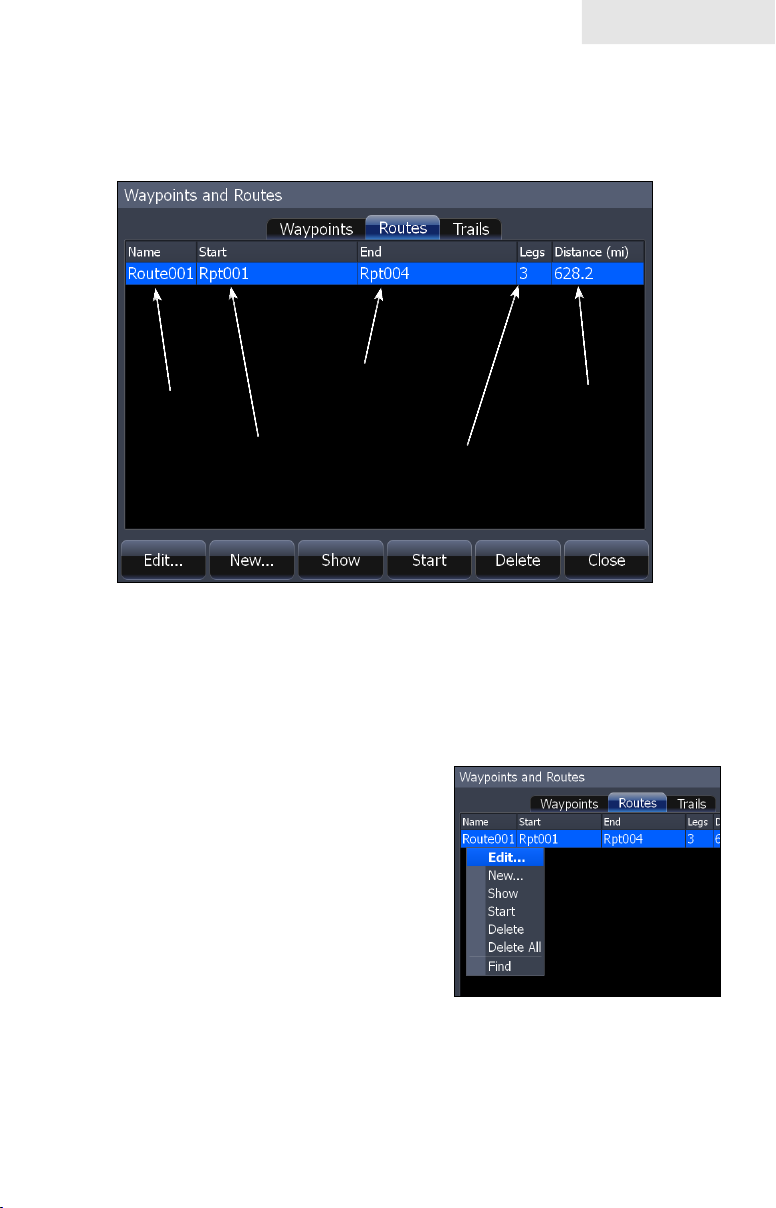
Routes screen
To view stored routes go to the Routes screen in the Utilities page. From the Routes
screen you can view and edit stored routes.
End of route
Route name
name.
Route length
Start of route
name.
Number of legs
in route.
Routes screen menu
From the Routes screen menu you can create a new route, edit a route or start a
route. To open the Routes screen menu, from the Routes screen, press the MENU
key. The following features are listed in the order they appear in the Route screen
menu, top to bottom:
Edit:• Opens the Edit Route screen.
New:• Opens the New Route
screen.
Show:• Shows the Route on the
Chart page.
Start:• Select to start navigating a
route.
Delete:• Deletes a selected route.
Delete All:• Deletes all routes in the
Route screen.
Find:• Use to search for routes in the Routes screen.
49
Page 52

Chart
To Edit Route:
From the Routes screen select 1.
the route to be edited and press
ENTER. The Edit Route screen
will appear.
From the Edit Route screen you 2.
can edit the route name, display
and waypoints in the route.
Use the Arrow keypad to select 3.
which route feature you want to
edit and press ENTER.
To Display / Hide Route:
From the Routes screen select the route from the routes list, press 1.
ENTER. The Edit Route screen will appear.
Highlight the Display check box and press 2. ENTER to either Display
or hide the route from the Chart page.
To Insert, Edit or Remove Waypoints from a Route:
1. From the Routes screen select a route from the route list, press
ENTER.
Edit Route screen
2. The Edit Route screen will appear.
Select a waypoint from the Waypoint
list, press MENU. A small submenu
will appear with the options: Insert,
Edit and Remove.
Select 3. Insert and press ENTER to
insert a waypoint into the route. To
remove a waypoint select Remove.
Selecting Edit will bring up the Edit
Waypoint dialog.
To Navigate Route from Routes screen:
S1. elect the route you want to navigate and press MENU. The Routes
screen menu will appear.
Select 2. Start from the Routes screen menu The Start Route dialog
will appear. Select Forward to navigate the route forward or Reverse
to navigate the route in reverse.
50
Page 53

Chart
To Search for Route by Name:
From the Routes screen press 1. MENU. The Routes screen menu
will appear.
From the Routes screen menu select 2. Find. A keypad will appear.
Use the keypad to enter the name of the route you are searching for
and press OK.
Trails
A trail is a record of the path you have traveled. Trails not only show you where you
have been, they can be used to retrace your path back to your starting point. On the
Chart page a trail is presented by a solid line extending from the back of the current
position icon.
From the factory, the unit is automatically set to create and record a trail when the
unit is turned on and you are navigating. The unit will continue to record a trail until
the trail length reaches the maximum trail point setting.
When the unit reaches the maximum trail point number it will automatically begin
recording the trail over itself. By default, the unit places a dot (trail point) on the
Chart page every time you change course.
Trails screen
To view stored trails go to the Trails screen in the Utilities page. From the Trails
screen you can view and edit stored trails.
Trail name
Indicates if Trail is displayed
on Chart page.
Trail color
Number of Trail
points.
Indicates if Trail is
being recorded.
51
Page 54

Chart
Trails screen menu
From the Trails screen menu you can create a new trail, edit a trail or delete a trail.
To open the Trails screen menu, press the MENU key from the Trails screen. The
following features are listed in the order they appear in the Trails screen menu, top
to bottom:
Edit:• Opens the Edit Trail
menu.
New:• Opens the New Trail
menu.
Show:• Brings up the Chart
page and shows the trail.
Display: • Select or deselect to
display or not display trail on
Chart page.
Record:• Select or deselect to
actively record a trail.
Delete:• Deletes a selected trail.
• Delete All: Select to delete all trails.
Trails screen menu
Find:• Use to search for trails in the Trails screen.
New Trail menu
You can edit a trail from the New Trail menu or from the Edit Trail menu once a
trail is created.
To Create a New Trail:
1. From the Pages screen, select Utilities
and press ENTER. The Waypoints and
Routes screen will appear.
From the Waypoints and Routes 2.
screen select Trails. The Trails screen
will appear.
3. From the Trails screen, press MENU.
The Trails screen menu will appear.
From the Trails screen menu select 4. New, press MENU. The New
Trail menu will appear, select Save.
New Trail menu
52
Page 55

Chart
Edit Trail menu
The Edit Trail menu is used to edit trail settings and coordinates. Use this menu to
change the trail name, trail color and description of a trail.
To edit a Trail name:
From the Trails screen 1.
select the trail to be edited,
press ENTER. The Edit
Trail menu will appear.
From the Edit Trail menu 2.
you can edit the name of
the trail by selecting the
trail name box and pressing
ENTER. The Edit Trail
name keypad will appear.
Use the keypad to enter
the desired trail name and
select OK.
Edit Trail menu
Trail line Color options
You can change the default trail line color from the Edit Trail More menu by selecting the Trail line color palette option.
Trail line color
palette menu
NOTE: If you record several overlapping trails, changing
the color of the different trail lines is a good way to keep them
separate when viewing them on the Chart page.
53
Page 56

Chart
Measuring Distances on Chart page
Use the Measure feature from the Chart menu to measure distances between yourself and another location on the Chart page or between two different points.
To select/deselect Measure feature:
From the Chart page press the 1.
MENU key. The Chart menu
will appear.
From the Chart menu select 2.
Measure.
When the cursor is on screen 3.
the cursor coordinates window
will display distance from your
position to the cursor position
on the Chart page.
To measure distance between two different points on the Chart 4.
page, place the cursor over a point and press ENTER, an X will
appear on the Chart page. Distance will be measured from the X on
the Chart page to wherever the cursor is placed on screen.
Search by Coordinates
To search for Chart page POI using coordinates:
From the Chart page press the 1.
MENU key. The Chart menu will
appear, select Find. The Find
menu will appear.
From the Find menu select 2.
Coordinate. The Find Coordinate
keypad will appear. Use the
keypad to enter the desired
coordinates and select OK.
Find Chart item
To search for specic Chart page item:
From the Chart page press the 1. MENU key. The Chart menu will
appear, select Find. The Find menu will appear.
From the Find menu select 2. Chart Items. The Find - Chart Items
screen will appear. Select Name, a keypad will appear. Use the
keypad to enter the name of the chart item and select OK.
54
Page 57

Chart
To view a list of specic Chart POI search options select Category from the
Find - Chart Items screen. A drop down list will appear. Select the specic
category from the drop down list.
Map Orientation
To change Chart page orientation:
From the Chart page press the 1. MENU key. The Chart menu will
appear, select Chart options. The Chart options submenu will
appear.
From the Chart options submenu select 2. Map Orientation. The three
Map Orientation options are: North Up, Heads Up and Course Up.
• North Up — Displays the Chart page
with North always at the top of the
screen.
Heads Up• — Displays the Chart page
in the direction the boat is facing.
• Course Up — Displays the Chart
page at the same orientation as your
initial bearing to a destination.
Look Ahead
Keeps your current position at the bottom of the Chart page to display more map
area in front of you.
To select / deselect the Look Ahead feature:
From the Chart page press the 1. MENU key. The Chart menu will
appear, select Chart options. The Chart options submenu will
appear.
55
Page 58

Chart
From the Chart options submenu select or deselect 2. Look Ahead to
turn this feature on or off.
Chart categories
Use the Chart Categories screen to control what you want to see on the Chart page.
To select / deselect Chart Categories:
From the Chart page press 1. MENU.
The Chart menu will appear; select
Chart options. The Chart options
submenu will appear.
From the Chart options submenu 2.
select Chart categories. The Chart
Categories screen will appear.
Select or deselect the chart options
you want to display on screen.
2D and Shaded Relief
(Shaded Relief only available on U.S. models)
To select between 2D and Shaded Relief:
From the Chart page press the 1. MENU key. The Chart menu will
appear. From the Chart menu select Chart options. The Chart options
submenu will appear.
From the Chart options submenu select 2. Imagery. The Imagery drop
down menu will appear with two map options: 2D and Shaded Relief.
Make your selection and press ENTER.
2D mapping
Shaded Relief, only available
on U.S. models.
56
Page 59

Chart
Chart page Icons, Tides and Currents
Use the cursor on the Chart page to view detailed information about selected icons,
including Tides and Currents.
The image, at left, shows a Current icon selected on the Chart page. To view
detailed information about an icon, press the MENU key then select Info from
the Chart menu. From the Chart Info screen, press Details.
Detailed information also can be viewed for Tide icons.
Radar Overlay
Places radar returns on top of the map.
That gives you greater awareness of your
surroundings by allowing you to see radar
returns aligned with actual radar targets.
To turn on radar overlay:
Highlight 1. Overlay on the Chart
menu and press ENTER.
Select 2. Radar and press
ENTER.
Radar Options menu
57
Page 60

Chart
Radar Options
The Radar Options menu appears when Radar Overlay is tuned on. It allows you to
customize the radar overlay settings from the Chart Page.
To access the Radar Options menu, select Radar Options from the Chart menu and
press ENTER.
Radar Options menu
Radar State Selects radar transmission mode
Adjust
Auto Gain
Sea Clutter
Transparency
Adjusts Gain, Sea Clutter, Rain Clutter, Interference
Rejection and Target Boost
Automatic Gain setting that is suitable for a variety of
conditions
Selects Sea Clutter setting from auto (harbor, offshore)
and manual settings.
Controls the transparency of radar overlay on the map To
make adjustments, highlight Transparency and press the
arrow keys left/right
NOTE: Radar State, Adjust, Auto Gain and Sea Clutter are
covered in more detail in the Radar Operation section.
Navionics
Your unit offers an unprecedented level of 2D and 3D mapping detail and numerous
mapping options, including Navionics chartcards. Navico mapping data is displayed
by default.
To view Navionics data:
Insert your Navonics card in the unit's MMC/SD card slot. 1.
Press 2. MENU twice, select Chart and press ENTER.
Highlight 3. Chart data and press ENTER.
Select 4. Navionics and press ENTER.
NOTE: You can use Navionics Platinum, Gold, Silver, Clas-
sic and HotMaps chartcards with your HDS unit.
58
Page 61

Chart
Navionics Settings menu
Use to customize the way Navionics data will be displayed on the Chart page, allow-
ing you to adjust the features best suited for your shing conditions.
To change Navionics Settings:
Select 1. Chart options from the Chart menu
and press ENTER.
Highlight 2. Settings and press ENTER.
Select a setting and press 3. ENTER.
Highlight the desired option and press 4.
ENTER.
Navionics Settings
menu
Navionics Settings and Options
Safety Depth• — Allows you to display the depth areas corresponding to the
safety contour desired. Available options are:
Off: No depth area displayed.
Other numeric depth values: The areas with depths up to value selected
are displayed in shades going from darker blue (for lower depths) to lighter blue (for higher depths). The areas whose depths are over the selected
value, and therefore navigable under safety conditions, will be displayed in
white. The Dryline areas are displayed in green.
Contours Depth• — Used to select the display of depth contours.
NOTE: When Night mode is selected, depth areas are dis-
played from lighter blue (for lower depths) to darker blue
(for higher depths). Depth areas over the value set are dis-
played in black.
Available options:
-5m: display depth contours up to 5 meters (16 feet)
-10m: display depth contours up to 10 meters (33 feet)
-20m: display depth contours up to 20 meters (66 feet)
-All: all depth contours are displayed
59
Page 62

Chart
Texture Type• — Enables (on) or disables (off) the 3D shading feature.
Photo overlay allows you to enable (full) or disable (off) the aireal photography overlay chart feature.
NOTE: These features are only applicable with Navionics
Platinum™ or Platinum Plus™ charts.
Annotation• — Allows you to display "Main" names (i.e. city names) only
or the "Full" set of names on the Chart page.
• Presentation Types — Is used for the selection of the symbols and colors
of the navigation chart "look and feel"; either U.S. or International "paper
chart" presentation types can be selected.
• Chart Details — This menu is used to select which object types and infor-
mation layers are displayed on-screen.
Available options:
Standard: Equivalent to standard display settings as defined in ECS regula-
tions.
All: Enables the display of all the object types and information layers on
the Chart page.
User: Allows selection of individual object types and information layers
on-screen.
60
Page 63

Radar Operation
Radar
Range Ring Size
Radar orientation indicator
To access the Radar Page:
North Indicator
Range Rings
Heading LineRange
Press the 1. PAGES key.
Use the keypad to select the 2. Radar Icon and press ENTER.
NOTE: You will only be able to see the Radar page if your unit
is connected to a radar.
Radar menu
Use the Radar menu to make adjustments to radar display
settings and features that not only change the appearance of
the display, but also make navigation easier.
To access the Radar menu, press the MENU key when the
Radar page is on the display.
61
Page 64

Radar
Radar State
Controls radar transmission modes: Off, Transmit and Standby. Off turns off the
radar. Transmit broadcasts a radar signal and standby leaves the radar on, but does
not broadcast a signal.
To select Radar State:
Press 1. MENU, highlight Radar State and press ENTER.
Select the desired state and press 2. ENTER.
NOTE: It can take 90 seconds or more to transition from Off
to Standby.
Adjust menu
From the Adjust menu you can make adjustments to Gain, Sea clutter, Rain clutter,
Interference rejection and Target boost.
To access the Adjust menu:
1. From the Radar menu select Adjust and press ENTER. The Adjust
menu will appear.
Highlight the desired setting and press the Arrow keypad left/right to 2.
make adjustments.
Gain
Controls the sensitivity of the radar receiver. Increasing gain
will show more detail on the screen; decreasing gain will show
less detail. Too much detail will clutter the screen. Conversely,
desired returns may not be shown if gain is too low.
Auto Gain
Selecting Auto gain from the Radar menu will automatically set the sensitivity of
the receiver to a level that works well under most conditions, reducing the need for
adjustments. If you make adjustments to the Gain level when Auto gain is on, Gain
will switch to manual mode.
To select Auto Gain:
Press the 1. MENU key. The Radar menu will appear
Select 2. Auto gain and press ENTER.
62
Page 65

Radar
Sea Clutter
Allows you to select the Sea Clutter adjustment mode — Auto or Manual. If you
make changes to Sea Clutter when it is in auto mode (Harbor or Offshore), Sea
Clutter will switch to Manual mode.
Sea Clutter Options
Manual Switches Sea Clutter from Auto to Manual mode
Harbor Auto setting optimized for harbor-like environment
Offshore Auto setting designed for offshore conditions
Rain Clutter
Precipitation reects radar signals, cluttering the screen. Interference Rejection
reduces or eliminates returns caused by rain, hail, sleet or snow.
Interference Rejection
Reduces interference from other active radars near your vessel. If another ship is
operating radar near you, interference from its radar signals can appear on your display. Increase interference rejection until radar interference is eliminated from your
display. Interference Rejection has four settings: Off, Low, Medium and High.
Target Boost (only available on some radars)
This feature increases the size of radar targets, making them easier to see on the
display. Target Boost has four options: Off, Low, Medium and High.
Clear Trails
Clears all target trails from the radar screen. New trails will continue to appear
unless you turn off the target trails feature.
To Clear Trails:
Press the 1. MENU key, the Radar menu will appear.
Use the Arrow keypad to select 2. Clear Trails and press ENTER.
63
Page 66

Radar
Position
You can move the PPI (Plan Position Indicator) to different locations on the radar
display. There are three Position options: Center, Look Ahead and Offset.
To change the PPI position:
Select Position from the Radar menu and press enter.1.
Select the desired position and press enter.2.
Position
Center
Look Ahead
Offset
Default setting, will position the PPI in the center of
the screen
Shifts the PPI to the bottom of the screen, allowing
you to see more of the area in front of your vessel
Allows you to move the PPI to a any location on the
display. If you shift the PPI to the right, you will see
more of what is to the left of your boat; if you move
the PPI forward you will be able to see more of the
area behind you
Center: PPI centered on the
display
Look Ahead: PPI moves down,
allowing you to see more of what
is in front of you
64
Page 67

Radar
Symbology on
Symbology off
Symbology
Used to turn on/off symbols displayed on the PPI screen, including range rings, range
markers and compass overlay. Rather than turn off each display feature individually,
the Symbology feature allows you to remove them all at once.
To toggle Symbology on/off highlight Symbology on the radar menu and press
enter.
EBL/VRM 1 EBL/VRM 2 EBL/VRM 1 & EBL/
VRM 2 Data Boxes
EBL/VRM
An Electronic Bearing Line (EBL) is a radial line used to show the distance of a
radar target to your vessel. A Variable Range Marker (VRM) is a range ring used to
measure the precise distance to a radar target. Selecting EBL/VRM from the Radar
Menu allows you to place up to two EBL/VRMs on the PPI display.
65
Page 68

Radar
EBL/VRM menu
Places selected Electronic Bearing Line and Variable
Range Marker on the display.
To select an EBL/VRM:
Press the 1. MENU key.
Use the keypad to select the 2. EBL/VRM and
press ENTER.
Use the keypad to move the EBL and increase/3.
decrease the size of the VRM. Press EXIT.
Adjust
Adjusts size and location of active EBL/VRM.
To adjust an EBL/VRM:
From the Radar menu highlight 1. EBL/VRM and press ENTER.
Select 2. Adjust and press ENTER.
Use the keypad to make adjustments to the EBL/VRM. Press 3. EXIT.
EBL/VRM menu
Data Box
Turns on/off on screen EBL/VRM information
box.
To turn on/off the EBL/VRM information box,
highlight Data box on the EBL/VRM menu and
press ENTER.
66
Data box
Page 69

Radar
Cursor position window
When the cursor is active on screen the Cursor position window appears in the
bottom left corner of the Radar page.
Cursor position window
Radar Overlay
Radar Overlay places radar returns on top of
the map on the Chart Page.
That gives you greater awareness of your
surroundings by allowing you to see radar
returns aligned with actual radar targets.
More information on Radar Overlay is available in the Chart Operation section of
this manual.
67
Page 70

Radar
Blank page
68
Page 71

Settings
Settings Menu
The Settings Menu provides access to installation and advanced conguration
settings for your unit. To access the Settings menu, press MENU twice.
Settings Menu Options
System Fuel Vessels
Page Alarms Simulator
Chart (if applicable) Trails Sirius (if applicable)
Radar (if applicable) Units
Sonar (if applicable) Network
System
Used to change system settings like units, language
and key beeps.
To access the System menu:
1. Press MENU twice.
Highlight 2. System and press ENTER.
System Menu
Language
Selects the language used on menus and dialog boxes. The default language is
English.
To select a language:
Select 1. Language from the System menu and press ENTER.
Highlight the desired language and press 2. ENTER. A window will
appear indicating the unit must restart to switch languages.
Select 3. Yes and press ENTER. The unit will restart.
Text Size
This unit will display text in two sizes: Small and
Normal. The Text Size menu allows you to select
the size of menu text.
69
Page 72

Settings
To change Text Size:
Highlight 1. Text Size from the System menu and press ENTER.
Use the keypad to select the desired text size and press 2. ENTER.
Key Beeps
By default, a tone (key beep) will sound when
any key is pushed on the unit. You can change
key beep volume or turn them on or off from the
Key Beep menu.
To change Key Beep settings:
Highlight 1. Key Beeps on the System menu and press ENTER.
Select the desired setting and press 2. ENTER.
Key beeps turned on
Time
Used to change local time to offset differences in time zone and to select the way
time and date will be displayed.
To set Time or Date format:
Highlight 1. Time on the System menu and press ENTER. The Time
menu will appear.
Select the Time format or Date format 2.
dropdown menu and press ENTER.
Use the keypad to select the desired 3.
format and press ENTER.
Highlight 4. OK and press ENTER.
To set Local Time:
Select 1. Local Time on the Time menu and press the keypad left/right
to select the desired offset.
Highlight 2. OK and press ENTER.
70
Page 73

Settings
Datum
A model of the earth’s surface based on a network of surveyed ground features
(points). This unit’s default datum is WGRS-84.
To select a Datum:
Select 1. Datum from the Chart settings menu and press ENTER.
Use the keypad to select the desired datum. Press 2. ENTER.
Coord System
Controls the coordinate system used when position coordinates are entered and
displayed.
To change Coordinate System:
Select 1. Coord System from the Chart settings
menu and press ENTER.
Highlight the desired option and press 2.
ENTER.
Magnetic Variation
Converts magnetic north data to true north, increasing the accuracy of navigation
information. The Magnetic Variance Auto setting, automatically converts magnetic
north to true north. When using manual mode, you will have to input the magnetic
variance.
To change magnetic variation settings:
Highlight 1. Magnetic Variation on the System menu. Press ENTER.
Select 2. Auto or Manual and press ENTER.
71
Page 74

Settings
Satellites
Satellite Status
Monitors the location of satellites in view and the quality of the unit’s satellite lockon. The Satellite page has two display options.
The Satellite screen displays a circular graphic that shows where satellites are
located and a bar graph that monitors the strength of satellites within range of your
unit. Your unit is locked on to satellites shown with blue bars.
To access the Satellite screen select Satellites from the System menu and press
ENTER.
72
Page 75

Settings
Screen Capture
Saves images of your unit’s screen to your unit. That allows you to capture images
of everything from underwater structure and sh to routes, map areas and radar
targets.
To take a screen capture:
Select1. Screen Capture from the System menu and press ENTER.
Press the2. LIGHT/POWER key to capture the current screen. Repeat
this step take additional screen captures.
To save screen captures to MMC/SD card:
Select 1. Files from the Utilities list on the Pages
menu. Press ENTER.
Highlight 2. My Files and press the keypad to the
right. Select screenshots and press the keypad
to the right.
Select the desired screenshot. Press 3. MENU.
The screenshot menu will appear.
Select 4. Copy and press ENTER. The Copy File
menu will appear.
Files selected on
Utilities list
Your MMC/SD card will be listed on the screen. Select your MMC/5.
SD card and press ENTER. You will be taken back to the list of
screenshots. Repeat Steps 3-5 to copy more screenshots.
Screenshot selected
Screenshot menu
MMC/SD card selected
73
Page 76

Settings
Restore Defaults
To switch the unit back to the settings it had when you purchased
it (default settings), use the Restore Defaults command. Reset
Defaults will reset the unit to default settings.
To Restore Defaults:
Highlight1. Restore Defaults on the System menu and press ENTER. A
conrmation message will appear.
Select 2. Yes and press ENTER. The unit will restart.
Advanced
A ne tuning adjustment for advanced users that allows duplicate waypoint names,
enables sticker backlight and slider hold off.
Advanced Settings menu (Enabling Flywheel scroll dial
setting is available only on HDS-8/10-inch units.)
To access Advanced Settings:
Select 1. Advanced on the Settings menu and
press ENTER.
Highlight a desired setting and use the right/left 2.
arrow keys to open (—) or close (+) the setting.
74
Page 77

Settings
To adjust Waypoint, Hardware, Flywheel and Radar settings :
Open the desired setting (—).1.
Highlight the setting information and 2.
press Enter to turn it on/off. The center
circle will be lled when the setting is
on; empty when it is turned off.
To adjust cursor settings:
Highlight the desired cursor setting and press 1. ENTER. A dialog box
will appear.
Use the arrow keys to select the desired value and press 2. ENTER.
About
Used to view your unit’s current software version. To check the unit’s software
version, highlight About on the System menu and press ENTER.
75
Page 78

Settings
Chart Settings Menu
Contains Chart settings ranging from display
options like Range Rings and Grid Lines to map
settings like Chart Data and Datum.
To access the Chart Settings Menu:
Press 1. MENU twice.
Highlight 2. Chart and press ENTER.
Chart Data
This unit can use mapping data from Navico and
Navionics. The Chart Data menu allows you to
select the desired map data (Navico 3D mapping
data available in US only).
To select chart data:
Highlight 1. Chart Data on the Chart
Settings menu and press ENTER.
Select the desired map data and 2.
press ENTER.
Chart Settings Menu
The Chart Settings menu
changes when Navionics is
the selected chart data type.
Range Rings
A navigation aid used to estimate distances.
Centered around your location, Range
Rings are placed a preset distance from
your location, allowing you to quickly
estimate distances while navigating.
To turn Range Rings On/Off, highlight
Range Rings on the Chart Settings menu
and press ENTER.
Range Rings
Heading Extension
A line extending from the front of the current position icon that is used to estimate
distance and time of arrival. The distance and estimated time of arrival is based on
the time interval selected from the Heading Extension menu.
76
Page 79

Heading Extension line
To use Heading Extension:
Highlight 1. Heading Extension from the chart menu and press
ENTER.
Select the desired time interval and press 2. ENTER.
NOTE: Range Rings and Heading Extension may not be
available in all chart data.
Popup Information
Turns on information windows that appear when
the cursor is centered on a point of information.
That allows you to identify POIs without having
to zoom in to see it on the screen.
To turn on/off Popup Information, highlight
Popup Information on the Chart Settings menu
and press ENTER.
Settings
Grid Lines
Displays base values for latitude and
longitude, making it easier to get a general
idea of your location on the latitude/
longitude scale.
To turn Grid Lines On/Off, select Grid
Lines from the Chart Settings menu and
Press ENTER.
Gridlines
Waypoints
Turns on/off waypoint display properties. When a large number of waypoints are on
the display, turning off waypoints will provide a better view of the map. To turn on/
off waypoint display properties, select Waypoints from the Chart menu and press
ENTER.
77
Page 80
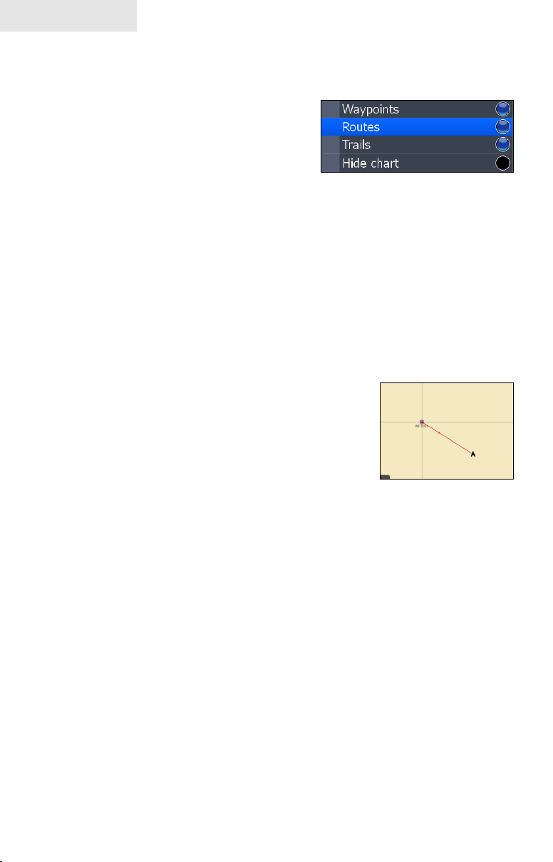
Settings
Routes
Turns on/off route display properties. When several routes are on the display,
turning off routes will give you a better view
of the map.
To turn on/off route display properties,
select Routes from the Chart menu and press
ENTER.
Trails
Turns on/off Trail display properties. When several trails are on the display, turning
off routes will give you a better view of the map.
To turn on/off trail display properties, select Trails from the Chart menu and press
ENTER.
Hide Chart
Removes mapping data from the display, making it easier
to view routes, waypoints and the cursor.
To turn on/off the map data, highlight Hide Chart on the
Chart Settings menu and press ENTER.
78
Hide Chart mode
Page 81

Settings
Sonar Settings Menu
The Sonar Settings Menu is used to modify Sonar
options and display settings like Sonar Source,
Noise Rejection and Fishing Mode.
To access the Sonar Settings:
Press 1. MENU twice.
Select 2. Sonar and press ENTER.
Sonar Settings Menu
Sonar Source
Selects the display unit that will be used for sonar data. Sonar Source allows you
to view selected transducer data on every display unit on the ethernet network;
even non-sonar units, like the GlobalMap. If you had an ethernet network and two
transducers — one at the bow and one in the back of the boat — you could view
sonar data from either transducer at the helm via the Sonar Source feature.
To select a Sonar Source:
Highlight 1. Sonar Source from the Sonar Settings menu and press
ENTER. The Sonar Source menu will appear.
Use the keypad to select the desired option and press 2. ENTER.
Network Sonar
Allows your unit to send/receive data from another sonar unit on an ethernet network.
To turn on/off network sonar, highlight Network sonar on the Sonar Settings menu
and press ENTER.
Noise Rejection
Sonar signal interference from Bilge pumps,
engine vibration, air bubbles, etc., can clutter your
unit’s display. Noise Rejection counteracts sonar
signal interference by reducing onscreen clutter.
To adjust Noise Rejection:
Highlight 1. Noise Rejection on the Sonar Settings menu and press
ENTER.
Use the keypad to select the desired option and press 2. ENTER.
79
Page 82

Settings
Surface Clarity
Wave action, boat wakes and temperature
inversion are some of the sources that can
cause onscreen clutter near the surface.
Surface Clarity reduces surface clutter by
decreasing the sensitivity of the receiver
near the surface.
To adjust Surface Clarity:
Select 1. Surface Clarity from the
Sonar Settings menu and press
ENTER.
Use the keypad to choose the desired option.2.
Surface Clutter
Scroll Speed
Controls how fast the sonar chart scrolls
across the screen. A slower scroll speed is
best suited for ice shing or shing while
at anchor. It is also useful when you want
to record a higher quality sonar log in deep water. By default, Scroll Speed is set to
normal.
To make adjustments, select Scroll Speed from the Sonar Settings menu and use the
keypad to make adjustments.
Manual Mode
Advanced user mode that bypasses digital depth to give you greater control of ping
settings. Digital depth causes the unit to search for the bottom regardless of the
portion of the water column you are targeting. While you still will get good results
using digital depth, it prevents you from getting optimum performance in certain
situations, like shing for suspended targets.
In Manual Mode the unit sends sonar signals (pings) only to the depth range you
select. Adjustments made to the range setting will be reected in your unit’s ping
speed. That makes it easy to get the best scrolling speed and the best screen resolution
for a selected range.
Select Manual Mode from the Sonar Settings menu and press ENTER to turn on/
off Manual Mode.
80
Page 83

Settings
Fishing Modes
Enhances the performance of your unit by providing preset packages of sonar
settings geared to specic shing conditions.
Settings optimized for shing modes include: Color Palette, Sensitivity,
Interference Rejection, Surface Clarity and Ping Speed, among others. Fishing
modes allow you to spend more time shing and less time adjusting settings.
Fishing Mode Options
General Use Bottom brown/blue background; 50% ping speed
Shallow Water
Fresh Water Bottom brown/white background; 50% ping speed
Deep Water
Slow Trolling Bottom brown/white background; 50% ping speed
Fast Trolling
Clear Water Bottom brown/white background; 50% ping speed
Brackish Water
NOTE: Use Shallow Water Fishing mode when shing in less
Bottom brown/white background; best suited for
depths less than 100 feet
Deep Blue; 50% ping speed; 50kHz is primary
transducer frequency
Bottom brown/white background; slightly lower chart
speed
Bottom brown/blue background; higher ASP; slightly
lower chart speed
than 100 feet of water.
Shallow Water Fishing Mode
Brackish Water Fishing Mode
81
Page 84

Settings
To select a Fishing Mode:
Select 1. Fishing Mode from the Sonar Settings menu and press
ENTER.
Use the keypad to select the desired mode and press 2. ENTER.
Reset Fishing Mode
Switches Fishing Mode to the default General Use setting. Select Reset Fishing
Mode from the Sonar Settings menu and press ENTER.
Installation Menu
Controls unit settings like Keel Offset, Water
Speed Calibration and Transducer Type only
for components (paddlewheel, temp sensor,
transducer) connected to this display unit
through the blue sonar connector. You can not
adjust settings of network components through
the Installation menu.
To access the Installation menu, highlight
Installation on the Sonar Settings menu and
press ENTER.
Sonar Installation menu
Keel Offset
All transducers measure water depth from the transducer to the bottom. As a result,
water depth readings do not account for the distance from the transducer to the keel
or from the transducer to the water surface. You can use Keel Offset to factor those
distances into the unit’s depth calculations.
Transducer
Keel Offset (-3.5 feet)
Accounting for the distance from the transducer to the keel will prevent you from
striking underwater objects or running aground, which could damage the keel.
Offsetting the distance from the transducer to the water surface will give you a more
82
Keel
Page 85
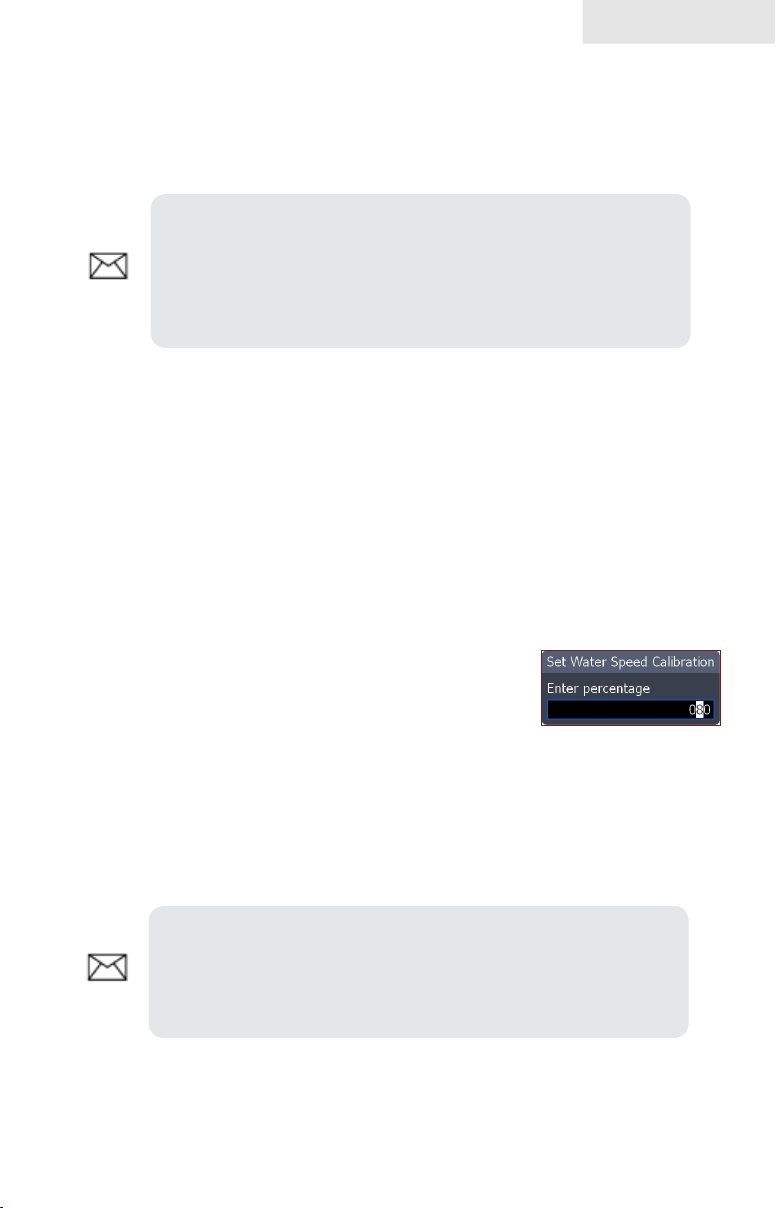
Settings
precise depth reading.
Before setting keel offset, measure the distance from the transducer to the lowest
part of the keel. If, for example, the keel is 3.5 feet below the transducer, it will be
input as –3.5 feet.
NOTE: To input a keel offset that accounts for the distance
from the transducer to the water surface, you will enter a positive number. If the transducer is 1.5 feet below the waterline,
it will be input as +1.5 feet. That will give you a more precise
depth reading.
To set Keel Offset:
Highlight the 1. Keel Offset text box on the Installation menu and press
ENTER.
Use the keypad to enter the desired keel offset. Select 2. OK and press
ENTER.
Water Speed Calibration
When there are differences in speed data, Water Speed Calibration calibrates
data from a paddlewheel with GPS data. That ensures the
accuracy of speed data from your paddlewheel.
To calibrate Water Speed:
Select the 1. Water Speed Calibration text box
from the Installation menu and press ENTER.
The Water Speed Calibration keypad will appear.
Use the arrow keys to enter the percentage difference in speed 2.
data. Select OK and press ENTER.
NOTE: If the paddlewheel is reading a slower speed than the
GPS unit, you will input a positive (+) percentage. Conversely,
a negative (–) percentage will be entered if the paddlewheel is
reading a faster speed than the GPS unit.
Water speed
calibration dialog box
83
Page 86

Settings
Water Speed Averaging
Averages water speed by measuring your speed at a selected interval. Water speed
intervals range from one to 30 seconds. If you select ve seconds, your water speed
will be recorded every ve seconds, then averaged.
To select a Water Averaging interval :
Highlight the 1. Water Speed Averaging box on the Installation menu.
Press the keypad left/right to select the desired interval.2.
Highlight 3. OK and press ENTER.
Temperature Calibration
When there are differences in temperature data,
Temperature Calibration calibrates data from one
temperature sensor with date from another temperature
source. That ensures the accuracy of temperature data
from the selected temperature sensor.
To calibrate Temperature:
Select the 1. Temperature Calibration text box from the Installation
menu and press ENTER. The Water Temperature Calibration dialog
box will appear.
Water Temp
calibration dialog box
Use the arrow keys to enter the percentage difference between 2.
temperature sources. Select OK and press ENTER.
NOTE: If the temperature sensor is reading a lower
temperature than the other temperature source, you will input a
positive (+) percentage. Conversely, a negative (–) percentage
will be entered if the temperature sensor is reading a higher
temperature than the other temperature source.
Temperature Averaging
Averages temperature by measuring temperature
data at a selected interval. Temperature intervals
range from one to 30 seconds.
If you select ve seconds, your temperature will be averaged using measurements
taken every ve seconds.
84
Page 87

Settings
To select a Temperature Averaging interval:
Highlight the 1. Temperature Averaging box on the Installation menu.
Press the keypad left/right to select the desired interval and press 2.
ENTER.
Reset Water Distance
If you connect a paddlewheel speed sensor to your unit, you can track the distance
you travel on the water. Reset Water Distance, resets water distance to zero.
To reset water distance, highlight Reset Water Distance and press ENTER.
Transducer Type
Selects the transducer model connected to your display unit. In some transducers
with built-in temperature sensors, the temperature may not be accurate if the correct
transducer is not selected from the Transducer Type menu.
To select a Transducer Type:
Highlight 1. Transducer Type box on the
Installation menu and press ENTER.
The Select Transducer menu will
appear.
Use the keypad to your transducer 2.
type and press ENTER.
Highlight 3. OK and press ENTER.
85
Transducer type menu
Page 88

Settings
Radar Settings Menu
Controls Radar options and display settings like Target
Expansion, Orientation and Bearings.
To access the Radar settings menu:
Press 1. MENU twice.
Select 2. Radar and press ENTER.
Radar Settings
Target Expansion
Increases the size of radar targets, making them easier to see on the radar display. To
turn on/off Target Expansion, highlight Target Expansion and press ENTER.
Target Trails
Creates an onscreen history of the movement
of radar targets, making it easier to monitor
the direction and position of targets in relation
to your vessel.
Menu
To set Target Trails:
Highlight 1. Target Trails on the
Radar Settings menu and press
ENTER.
Use the arrows to select an 2.
interval and press ENTER.
Target Trails
Palette
Radar echoes can be displayed in black, white, green or yellow. The Palette feature
allows you to select the color that suits your viewing preferences.
To change the Palette:
Highlight 1. Palette on the Radar Settings menu and press ENTER.
Use the keypad to select the desired color palette and press 2.
ENTER.
86
Page 89

Settings
Black Color Palette
White Color Palette
Orientation
Controls the way the map moves in relation to the movement of your vessel. That
allows you to select a desired method for viewing your surroundings on the radar
display.
• Course Up — map stays at same orientation as the initial bearing to the
selected waypoint.
• Heading Up — unit keeps your heading at the top of the screen, regardless
of the direction you are traveling.
• North Up — North is always shown at the top of the screen.
To change Map Orientation:
Highlight 1. Map Orientation on the Radar
Settings menu and press ENTER.
Use the keypad to select the desired 2.
option and press ENTER.
Threshold
Controls the level of radar returns. That allows you to unclutter the display by
removing unwanted signals. The zero percent setting allows all To make adjustments,
select Threshold and press the keypad left/right.
North Indicator
The North indicator is shown on the outer circle of the radar display. To turn on/
off North Indicator, select North Indicator from the Radar Settings menu and press
ENTER.
87
Page 90

Settings
Range Rings
Allows you to quickly estimate the distance
from your vessel to a another radar target.
To turn on/off Range Rings, highlight Range
Rings on the Radar Settings menu and press
ENTER.
Range rings
Range Markers
Located below each Range Ring, Range
Markers display the distance from your position
to each range ring.
To turn on/off Range Markers, select Range
Markers from the Radar Settings menu and
press ENTER.
Compass
Range markers
A Compass overlay can be displayed on the background of the radar page. To turn
on/off the Compass overlay, select Compass and press ENTER.
Compass Overlay turned off Compass Overlay turned on
Bearings
Bearings allows you to choose if you want the direction you are headed to show
as True Magnetic (TM) or Relative (R). T/M or True/Magnetic will show your
direction based on magnetic north. R or Relative will show your direction based on
your relative heading.
88
Page 91

To set T/M or R:
Press 1. MENU twice.
Select 2. Radar and press ENTER.
Highlight 3. Bearings and press ENTER.
Use the arrows to select a bearing and press 4. ENTER.
Installation
Provides access to the Radar Installation menu.
Settings
Radar Installation menu
To access Radar Installation menu:
1. Press the MENU key twice.
2. Highlight Radar and press ENTER.
3. Select Installation and press ENTER.
Installation Adjustment Menu
The installation adjustment menu is used to make adjustments to bearing alignment,
range offset, antenna height and open array park angle.
When the installation adjustment menu is accessed, press the
keypad up/down to select a feature. Press the keypad left/right
to make adjustments to a selected feature.
Press EXIT to return to the Radar Installation menu. To remove
the Radar Installation menu from the screen, select Close and
press ENTER.
Adjustment Menu
89
Page 92

Settings
Bearing alignment
Used to align the bow of your vessel with the heading line (zero point). Bearing
alignment is also referred to as zero bearing.
To make adjustments to bearing alignment, switch the radar state to Transmit and set
radar orientation to Heading Up.
To select Heading up orientation:
1. From the Radar Page, press MENU.
2. Select Orientation and press ENTER.
3. Use the keypad to select Heading Up and press ENTER.
4. Press EXIT.
Before Bearing Alignment
Bow of ship is lined up with
the tip of a peninsula; the
bearing line is not.
To Adjust Bearing Alignment:
1. Line up the bow of your vessel with a stationary target (lighthouse,
pier, etc) at least 1 nm away
Select 2. Adjust Bearing Alignment from the Radar Installation menu
and press ENTER. The Installation Adjustment menu will appear.
Press the keypad left/right to rotate the radar image so the reference 3.
target is at 0° or 12 o’clock from the radar center.
After Bearing Alignment
Bearing line aligned with
peninsula, matching the
alignment of the bow.
90
Page 93

Settings
Range offset
Eliminates the time lag between real radar returns and the time it takes data to be
processed by the radar software. Range Offset is also referred to as zero range and
trigger delay.
Range Offset Sequence. The circle shrinks as range is increased.
To Adjust Range Offset:
Use the 1. ZOOM IN/ ZOOM OUT keys to set range to 1/8 nm.
Highlight 2. Adjust range offset from the Radar Installation menu and
press ENTER. The installation adjustment menu
will appear.
Press the keypad to the left set range offset to 0. 3.
Press ENTER.
If there is a blank, black circle around the center or 4.
a solid circle of color at the center, increase the range offset until the
circle disappears or almost disappears.
If you increase th range offset too far, decrease it until the circle 5.
appears again.
Antenna Height
Antenna height is the distance from the waterline to the Antenna (scanner). It is
important to correctly input antenna height to prevent problems with the Sea Clutter
feature.
To Adjust Antenna Height:
Select 1. Adjust Antenna Height from the Installation menu and press
ENTER.
Press the keypad left/right to input the distance from the antenna to 2.
the water surface. Press EXIT.
91
Page 94

Settings
Open Array Park Angle
When an open array antenna is turned off, the antenna’s momentum will cause it
to continue rotating before coming to a stop. Open array park angle allows you to
adjust the antenna’s parking angle so it will stop in a desired position.
To Adjust Open Array Park Angle:
Select 1. Adjust Bearing Alignment from the Radar
Installation menu and press ENTER. The
Installation Adjustment menu will appear.
Press the keypad left/right to enter a value that will 2.
cause the antenna to stop in the desired position.
Tune
You should not have to adjust Tune for the life of this unit. This feature is intended
for use by only trained technicians.
Reset Radar to Factory Defaults
Resets radar to factory default settings.
92
Page 95

Settings
Fuel
Used to input fuel data like engine/tank conguration,
fuel tank capacity and engine calibration. Your unit uses
that data to calculate the overall fuel performance of your
vessel. To access the Fuel menu, select Fuel from the
Settings menu and press ENTER.
Refuel
Controls engine calibration and is used to input the amount of fuel added to the
tank(s). Engines must be calibrated with your fuel tanks to get correct readings on
fuel economy, fuel used, etc.
Amount Added
window
Fuel menu
Amount
Added text
box: Input
amount of fuel
added here
Refuel menu
Set to Full
checkbox: Check
this box when you
ll up your tank
It is important to enter the amount of fuel added to your tank(s) each time fuel
is added. That ensures the correct fuel data is used in the unit’s fuel performance
calculations.
To input fuel added:
Select 1. Refuel from the Fuel menu and press ENTER.
Use keypad to select the Amount Added window and press enter. 2.
The Amount Added text box will appear.
Use the keypad to input the amount of fuel added and press 3.
ENTER.
93
Page 96

Settings
To set tank to full:
Highlight the 1. Set to full checkbox
on the Refuel screen and press
ENTER.
Highlight 2. OK and press ENTER.
The calibration options screen will
appear. You are
ready to calibrate.
To calibrate engine(s):
With the calibration options screen displayed, select the checkbox 1.
next to the engine you would like to calibrate .
Highlight 2. OK and press ENTER. The Calibration screen will
appear.
Tank set to full
Calibration options screen
Use the keypad to highlight the Actual amount used window and 3.
press ENTER.
Input the amount of fuel used in the Actual amount used dialog box 4.
and press ENTER.
Highlight the 5. Next button and press ENTER. The Conrm calibration
screen will appear.
After conrming calibration data, highlight 6. OK and press ENTER.
Calibration screen
94
Page 97

Settings
Fuel Used
Data information screen that displays fuel
consumption data including fuel used
since last ll up, fuel used on the current
trip and fuel used during a season.
To access fuel used information, select
Fuel Used from the Fuel menu and press
ENTER.
Highlight the Reset button and press
ENTER to set corresponding fuel data
values (trip and seasonal) to zero.
Vessel Setup
Controls vessel conguration, which includes selecting the number of engines/
fuel tanks and inputting the capacity of each fuel tank. Vessel Setup data must be
congured before you can calibrate your engine(s).
To access the Vessel Setup menu, highlight Vessel Setup on the Fuel menu and press
ENTER.
Fuel used screen
Vessel
conguration
menu: select
number of
engines and fuel
tanks here
Calibration
info button: get
calibration info
here
Tank size text
box: input
tank size here
Tank size
window
Vessel Setup
95
Page 98

Settings
Engine/Tank Conguration
Used to input the number of engines and fuel tanks on your vessel. Your unit must
have that information to be able to calibrate you engine(s).
To select engine-tank conguration:
Highlight the vessel conguration drop-down 1.
menu and press ENTER.
Select a engine/tank conguration and press 2.
ENTER.
Highlight the 3. Save button and press ENTER.
To input tank size:
Highlight the 1. Tank Size window and press ENTER. The Tank Size
Text box will appear.
Use the keypad to input the size of the 2.
selected tank and press ENTER.
Repeat Step 2 for each tank on your 3.
vessel.
Select the 4. Save button and press
ENTER.
Calibrate
Launches engine calibration information window
referring you to your fuel sensor’s installation
manual.
96
Page 99

Settings
Alarms
This unit has alarms covering everything from depth and water temp rate to fuel and
waypoint radius. The alarms list has three tabs: Active, History and Settings.
Active — used to view alarms that have been enabled•
History — shows log of alarm activity, which includes data like when •
alarms were triggered and when they were cleared
Settings — provides access to Alarms list, allowing you to enable •
alarms and set alarm limits
NOTE: Some alarms will not work unless a corresponding
sensor is connected to the unit or the network.
To enable/disable an Alarm:
Select 1. Alarms from the Settings menu and press ENTER.
Highlight 2. Settings and press ENTER.
Select the desired alarm from the alarms list and press 3. ENTER.
Displays list of
enabled alarms
Enabled
Alarm
Shows history of
Alarms List
alarm activity
97
Enable alarms and set
limits (thresholds)
Alarm Limits (Thresholds)
Page 100

Settings
To silence an alarm:
When an Alarm is triggered, a tone will sound and a alarm window will appear on
the screen. Press ENTER to silence the alarm and close the alarm window.
After alarm is silenced its corresponding alarm bell will continue to ash
in the bottom left corner of the screen. To remove the bell from the screen,
disable the alarm and then enable it again. The bell will not reappear unless
the alarm is triggered.
Set Limit
Sets thresholds (limits) that will trigger the alarm when met or exceeded. If a
threshold can be set for a particular alarm, the Set Limit button will appear at the
bottom of the screen when that alarm is highlighted on the alarm list.
To set alarm limit:
Highlight the desired alarm on the alarm 1.
screen and press MENU.
Select 2. Set Limit and press ENTER. The
Alarm Limit keypad will appear.
Input the desired alarm threshold and 3.
press ENTER.
Siren Enabled
When the Siren is enabled, a tone will sound when an
alarm is triggered. To enable alarm sirens, highlight
Siren Enabled on the Alarms menu and press
ENTER.
98
Set limit selected on Water
Temp Rate menu
 Loading...