

Page 1

988-0176-02B
HDS-5m & HDS-7m
GPS Mapping Receiver
Operations Guide
Page 2

Software updates for your unit.
Occassionally check the Lowrance website for free software upgrades for your
unit. Go to www.lowrance.com for the software upgrades. Select the Down-
loads option from the grey menu bar near the top of the Lowrance website
homepage. The Downloads screen will appear. Select Products Software
Updates from the list on the left side of the screen. The Products Software
Updates screen will appear. Scroll through the Product list and select your unit
to download the software update.
Page 3

Contents
Table of contents
Introduction ....................................................................................... 3
Getting Started ................................................................................. 5
Turning on the Unit ..................................................................................... 5
Keypad .......................................................................................................5
Backlight ....................................................................................................5
Cursor ........................................................................................................ 5
Language ................................................................................................... 5
Menus ........................................................................................................6
Selecting Chart Data ................................................................................ 6
Entering Letters in Text Boxes ................................................................... 7
Restore Defaults ........................................................................................7
Pages ................................................................................................. 9
Pages Screen ............................................................................................ 9
Data Overlay ............................................................................................ 10
Conguration menu ................................................................................. 14
Chart Page ............................................................................................... 15
Radar Page .............................................................................................. 16
Info Page .................................................................................................. 16
Utilities ..................................................................................................... 21
Displaying Combo Pages ........................................................................ 23
Chart Operation............................................................................... 25
Waypoints ................................................................................................ 28
Routes ...................................................................................................... 33
Trails ......................................................................................................... 37
Measuring Distances on Chart page ....................................................... 40
Search by Coordinates ............................................................................40
Find Chart item ........................................................................................40
1
Page 4

Contents
Map Orientation ....................................................................................... 41
Look Ahead .............................................................................................. 41
Chart categories ...................................................................................... 42
2D and Shaded Relief ............................................................................. 42
Navionics .................................................................................................44
Radar Operation ............................................................................. 47
Radar menu ............................................................................................. 47
Cursor position window............................................................................ 53
Radar Overlay ..........................................................................................53
Settings Menu ................................................................................. 55
Chart Settings Menu ................................................................................ 62
Radar Settings Menu ............................................................................... 65
Fuel .......................................................................................................... 72
Alarms ......................................................................................................76
Trails ......................................................................................................... 78
Units .........................................................................................................79
Network .................................................................................................... 80
Vessels ..................................................................................................... 87
Simulator ..................................................................................................89
Specications .................................................................................. 93
Unit Care ..........................................................................................94
Troubleshooting .............................................................................. 95
Index ............................................................................................... 103
2
Page 5

Introduction
Introduction
Thank you for purchasing from Lowrance, the industry leader in marine technology.
This manual is packaged with a Quick Start Guide, Installation Guide, License and
Warranty booklet and NMEA 2000 Networks Installation Instructions. If any of
these documents are missing, you may acquire them via a free download at www.
lowrance.com or by contacting customer service.
Lowrance Customer Service
12000 E Skelly Dr
Tulsa, OK 74128
(800) 324-1356
Canada (800) 661-3983 or (905) 629-1614
About this manual
This manual documents how to adjust features and options in your display unit. The
information in each section follows the same sequence as your display unit’s menus.
If you would like information on how to get the most out of your unit, visit our web
site, www.lowrance.com; click on the Support tab and select Tips and Tutorials.
Manual Conventions
When you are instructed to press a button in this manual, the button will be shown
in all caps and bold text like — MENU, EXIT, ENTER, etc. If you are instructed
to select an item from a menu, the item to be selected will be listed in bold like —
Brightness, Key beeps, etc.
For example: Press MENU, select Language and press ENTER.
WARNING: When a GPS unit is used in a vehicle, the
vehicle operator is solely responsible for operating the
vehicle in a safe manner. Vehicle operators must maintain full surveillance of all pertinent driving, boating or
ying conditions at all times. An accident or collision resulting in damage to property, personal injury or death
could occur if the operator of a GPS-equipped vehicle
fails to pay full attention to travel conditions and vehicle
operation while the vehicle is in motion.
3
Page 6
Introduction
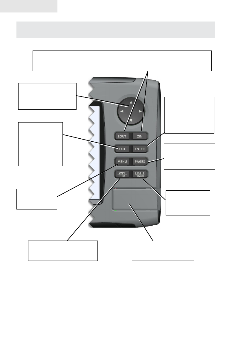
Lowrance HDS-5m & 7m
ZOUT: Zoom out to see more of the map with less detail
ZIN: Zoom in to see less of the map with more detail
MOB: Pressing ZOUT and ZIN at the same time will set a man overboard waypoint
KEYPAD: move the
cursor, scroll through
menus, adjust features,
view sonar/GPS history
EXIT: cancels
entries, closes
menus & windows;
toggles between
cursor position and
chart location on
Chart page
ENTER: nalize
menu selections;
shortcut key for
functions like saving
a waypoint at cursor
position
PAGES: opens Pages
menu; selects active
panel for combo
display
MENU: opens
context &
settings menus
WPT/FIND: saves a waypoint
at current position; accesses
searching tools
LIGHT/POWER:
controls backlight
level & turns the
unit on/off
MMC/SD Card slot: insert
MMC/SD and high-detail
mapping cards here
4
Page 7
Getting Started
Getting Started
Turning on the Unit
Press the POWER/LIGHT key to turn on the unit. If the unit is not connected to
a transducer, the unit will start up in simulator mode. To turn off the unit,
press the POWER/LIGHT key for three seconds.
Keypad
This unit’s keypad can be used in two ways. Pressing the arrow symbols on the keypad will move the cursor in the corresponding direction on the screen and allow you to scroll through menus.
Keypad
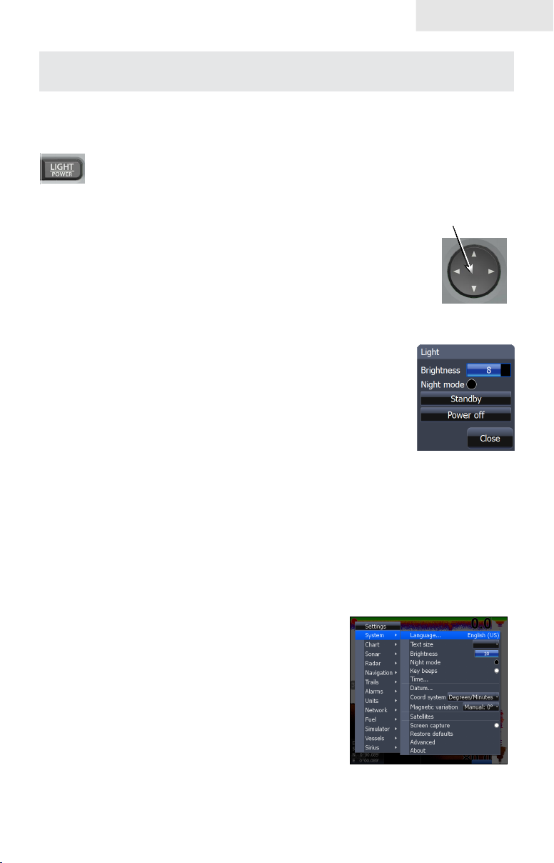
Backlight
Tap the LIGHT/POWER key to make adjustments to the
backlight level and open the Backlight Menu. To turn on Night
Mode from the menu, highlight Night Mode and press ENTER.
Night mode optimizes the display for low light conditions.
Cursor
Use the unit’s keypad to move the cursor around the display, select onscreen objects,
highlight data items and view sonar history. Press EXIT to remove the cursor from
the screen.
Language
Selects language used for menus, text boxes and messages.
To select a language:
Press 1. MENU twice.
Select 2. System and press ENTER
Highlight 3. Language and press ENTER.
4. Use the keypad to select a language
and press ENTER.
5
Page 8
Getting Started
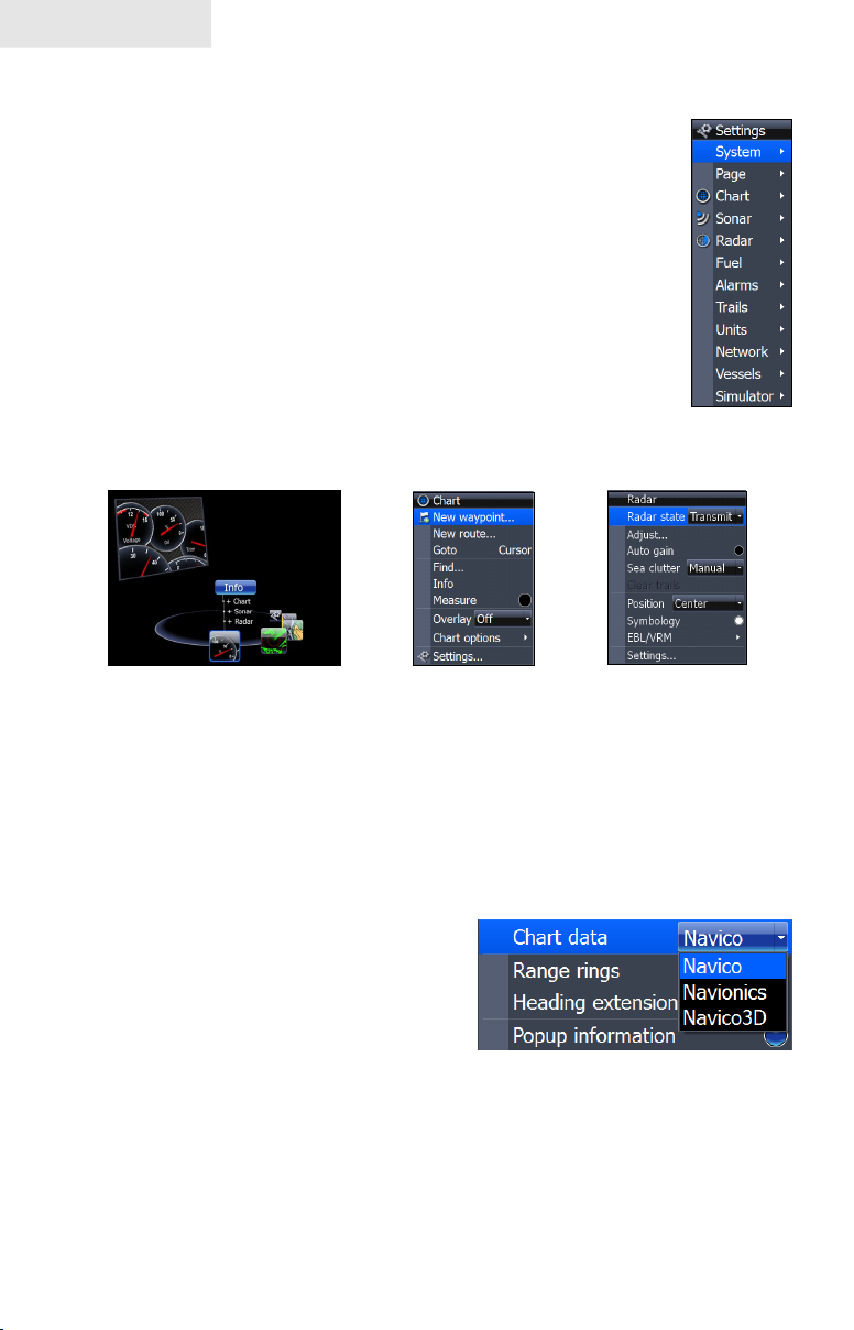
Menus
This unit has a Settings menu, a Pages screen and several context
menus. The Settings menu provides access to the settings menus for
the three main operation modes: Chart and Radar. The Settings menu
is accessed by pressing MENU twice.
The Pages screen allows you to select a page to be shown on the
display. Utilities are also accessed from the Pages screen. Press the
PAGES key to select a page.
Each page has its own context menu which allows you to access
functions for that page. Context menus are accessible only when its
corresponding page is displayed. To access a context menu, select the
desired page and press the MENU key.
Settings
menu
Pages screen
Chart menu
Radar menu
Closing Menus
Press the EXIT key to close a menu. Repeatedly pressing EXIT will close all menus,
taking you back to the main screen.
Selecting Chart Data
This unit supports three types of map data:
Navico, Navionics and Navico 3D (US only).
To use Navionics or Navico 3D data, you
must select it from the Chart Data menu.
To select Chart data:
Press 1. MENU twice.
Highlight 2. Chart and press ENTER.
Select 3. Chart Data and press ENTER.
Select the desired map data option and press 4. ENTER.
6
Page 9
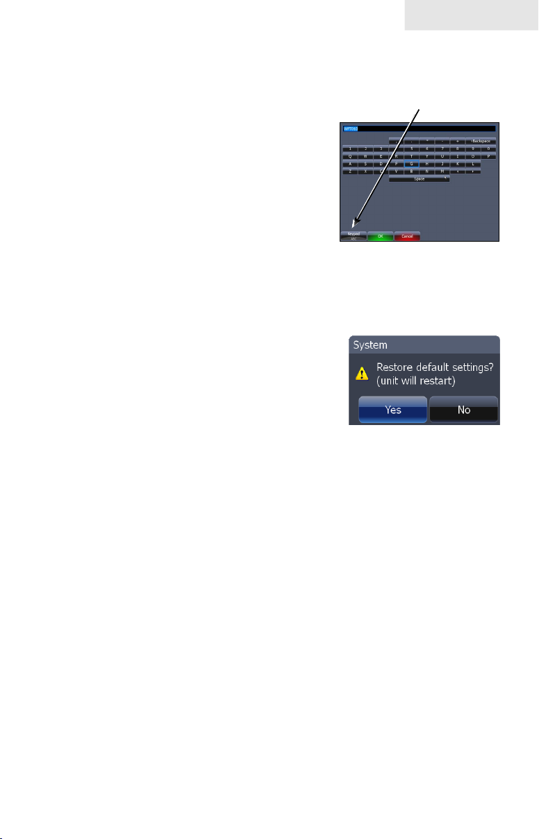
Entering Letters in Text Boxes
This unit has some features and functions that may
require you to enter data in a text box.
To enter data in a text box:
Highlight the text box and press 1. ENTER.
A keyboard will appear on the screen.
Use the keypad to highlight the rst 2.
character and press ENTER. Repeat
this step until all characters have been
entered.
Highlight 3. OK and press ENTER.
Restore Defaults
The Restore Defaults command switches the unit back
to the settings it had when you purchased it (default
settings),
To Restore Defaults:
Getting Started
Keypad button controls
uppercase & lowercase
Keyboard window
Press 1. MENU twice.
Select 2. System and press ENTER.
Highlight3. Restore Defaults and press ENTER. A conrmation message
will appear.
Select 4. Yes and press ENTER.
7
Page 10

Getting Started
Blank page
8
Page 11
Pages
Combo
display
options
allows you
to display a
split screen
Pages
Page icons
rotate around
the circular
Pages
menu
Page Icons
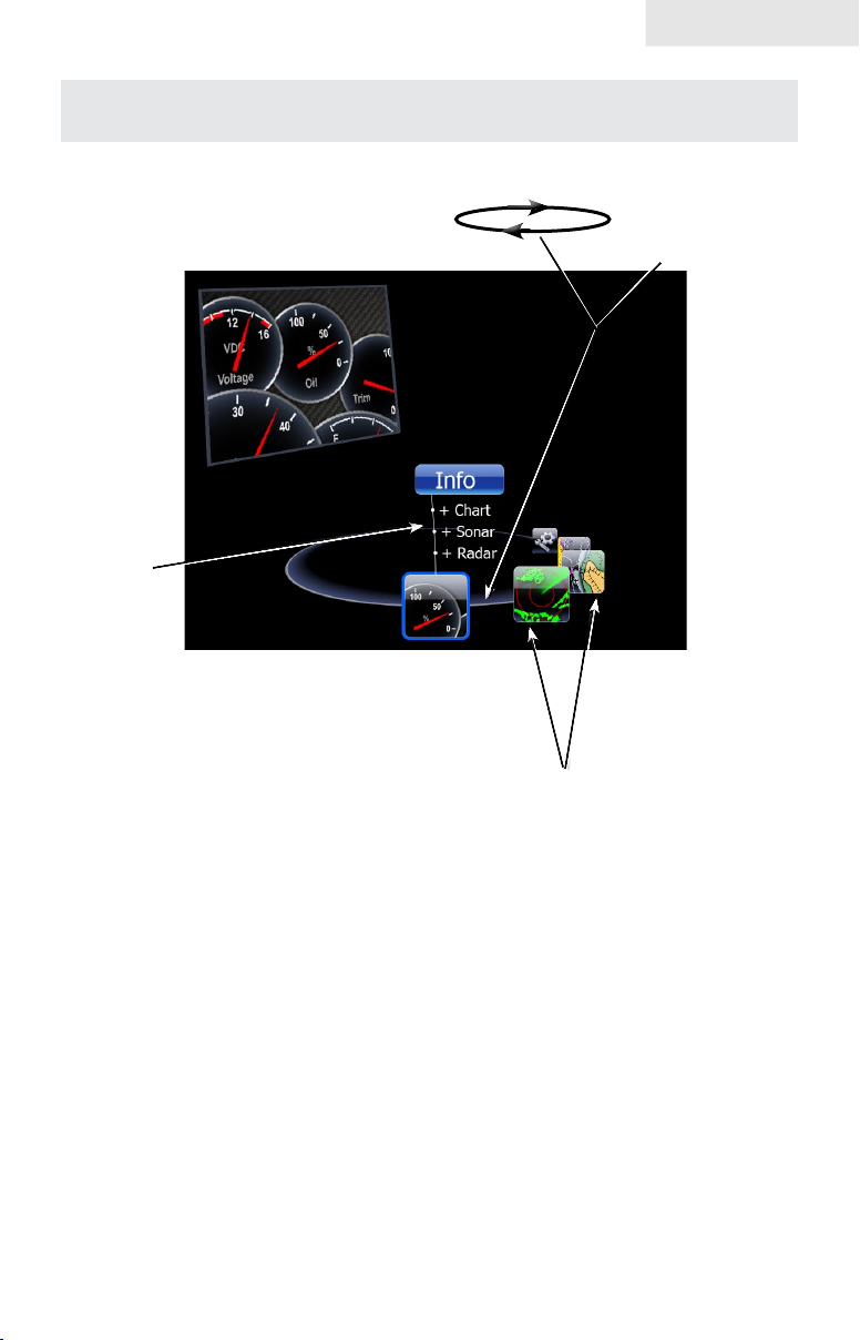
Pages Screen
Consists of four page icons that scroll horizontally around the Pages menu. To view the pages screen,
press the PAGES key.
Selecting Pages
Pressing the keypad left or right will move the page icons around the menu. To select a page, move
the desired page icon to the center of the screen.
When selected, the page name will be highlighted in blue at the top of a list of combo display options.
Its icon, will be framed by a blue border below the list. To display the page, press ENTER.
9
Page 12
Pages
Data Overlay
Data overlay is information you can display on top
of the page screen, allowing you to customize each
page with desired data.
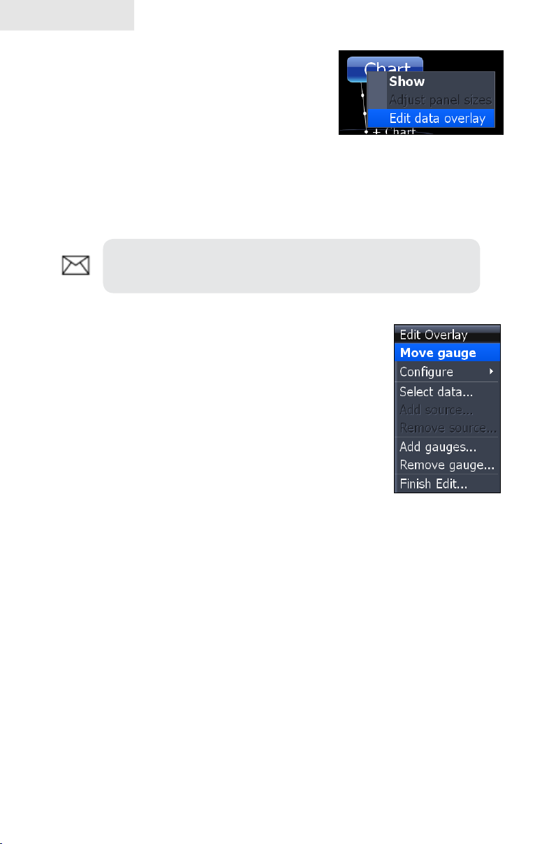
Data Overlay menu
Every page option has its own Data Overlay menu. The menu allows you to edit,
add or remove overlay data from the display. To access Data Overlay menu, select
a page option and press MENU.
NOTE: Adjusting Panel Sizes is covered later in this section in
the Displaying Combo Pages segment.
Edit Overlay menu
Accesses data overlay options for all the unit’s page screens.
To access Edit Data Overlay menu:
1. Select Edit Data overlay from the Data Overlay
menu and press ENTER.
Press 2. MENU. The Edit Overlay menu will appear
with Add Gauge selected.
10
Edit Overlay menu
Page 13
Pages
Edit Mode
When a gauge is added to the display it will be shown in edit mode. Analog and
bar gauges are shaded in blue when they are in Edit Mode. Digital Gauges will be
shown with a blue border.
Analog gauge in edit
mode
Move or Placing a Gauge
The Move gauge command allows you to move data overlay to any position on the
screen. When you use the Place gauge command, the gauge will be locked in its
current position.
To move or place a gauge:
Press the 1. ENTER key when the gauge is in Edit
mode. Four directional arrows will appear when
the gauge can be moved.
Use the keypad to move the gauge to a desired 2.
location on the screen.
Press 3. ENTER to place the gauge.
Select Data
Used to select data that will be shown on the data overlay display. When selecting
data you rst will open a main data category and then choose data to be displayed
from the a data subcategory.
Digital gauge in edit mode
11
Page 14
Pages
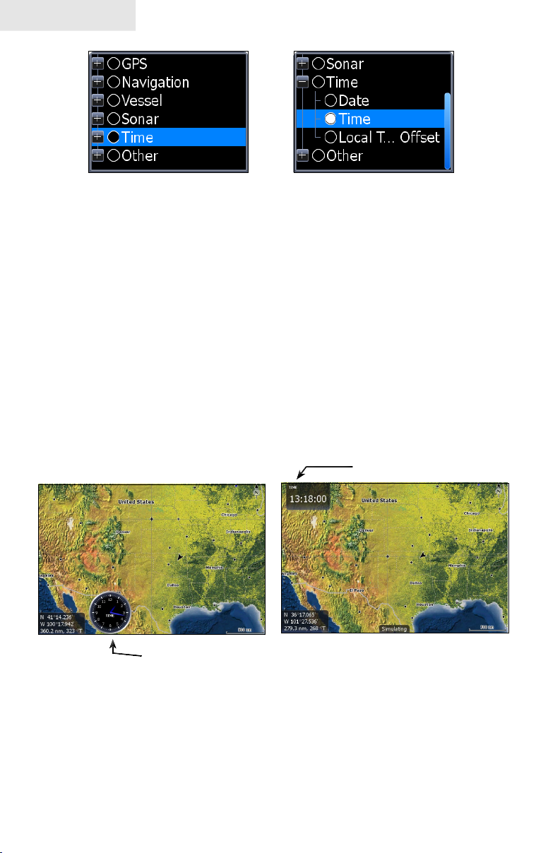
Select data menu
Time subcategory
To select data overlay:
1. Highlight Select data on the Congure menu. The Select Data menu
will appear.
Use the keypad to select the desired category and press 2. ENTER. A
list of subcategories will appear.
Select the desired subcategory and press 3. ENTER.
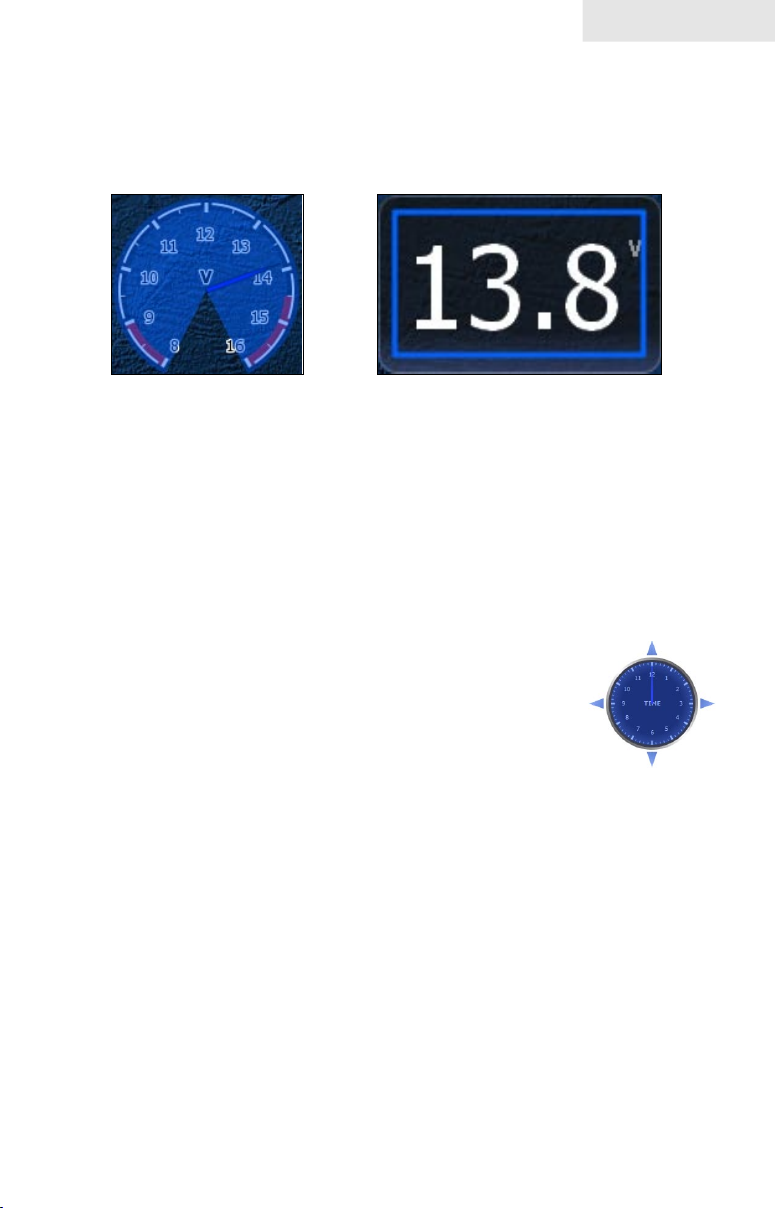
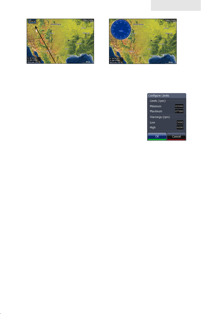
Type
Switches data overlay display between analog, digital and bar gauge formats,
provided the format is appropriate for the selected data type.
Highlight Type on the conguration menu and press ENTER to choose between
digital and analog gauge formats.
Time in digital format
Time in analog format
Size
Selects the size of the data overlay display. Data overlay can be displayed in four
sizes.
With the gauge in edit mode (shaded in blue) press the ZOOM OUT key to increase
overlay size; press the ZOOM IN key to decrease overlay size.
12
Page 15
Pages
Small digital gauge
Large analog gauge
Limits
Controls the number scale used on data overlay gauges and
selects warning thresholds. Changing the limits on an analog
or bar gauge removes unnecessary numbers from the gauge,
making them easier to read. Warnings help you stay within
selected warning thresholds.
Limits are congured by inputting analog or bar gauge limits
in the Limits text boxes — minimum and maximum. Warnings
thresholds are entered in the Low and High text boxes.
To congure limits:
Select 1. Limits from the conguration menu. The Conguration Limits
menu will appear.
Select the Limits or Warnings text box and press 2. ENTER.
Use the keypad to enter the desired threshold.3.
Select 4. OK and press ENTER.
To save changes:
Conguration
Limits menu
Press 1. MENU and highlight Save.
Press 2. ENTER.
13
Page 16
Pages
Conguration menu
Allows you to Add/Remove sources and adjust Bezel, Caption
and Invert Text Settings. Other conguration menu options are
covered previously in the section.
To access the Conguration menu, highlight Conguration on
the Edit Overlay menu and press ENTER.
Conguration Settings
Bezel
Caption Allows you to add/remove data label from gauge
Invert Text Changes appearance of data overlay text
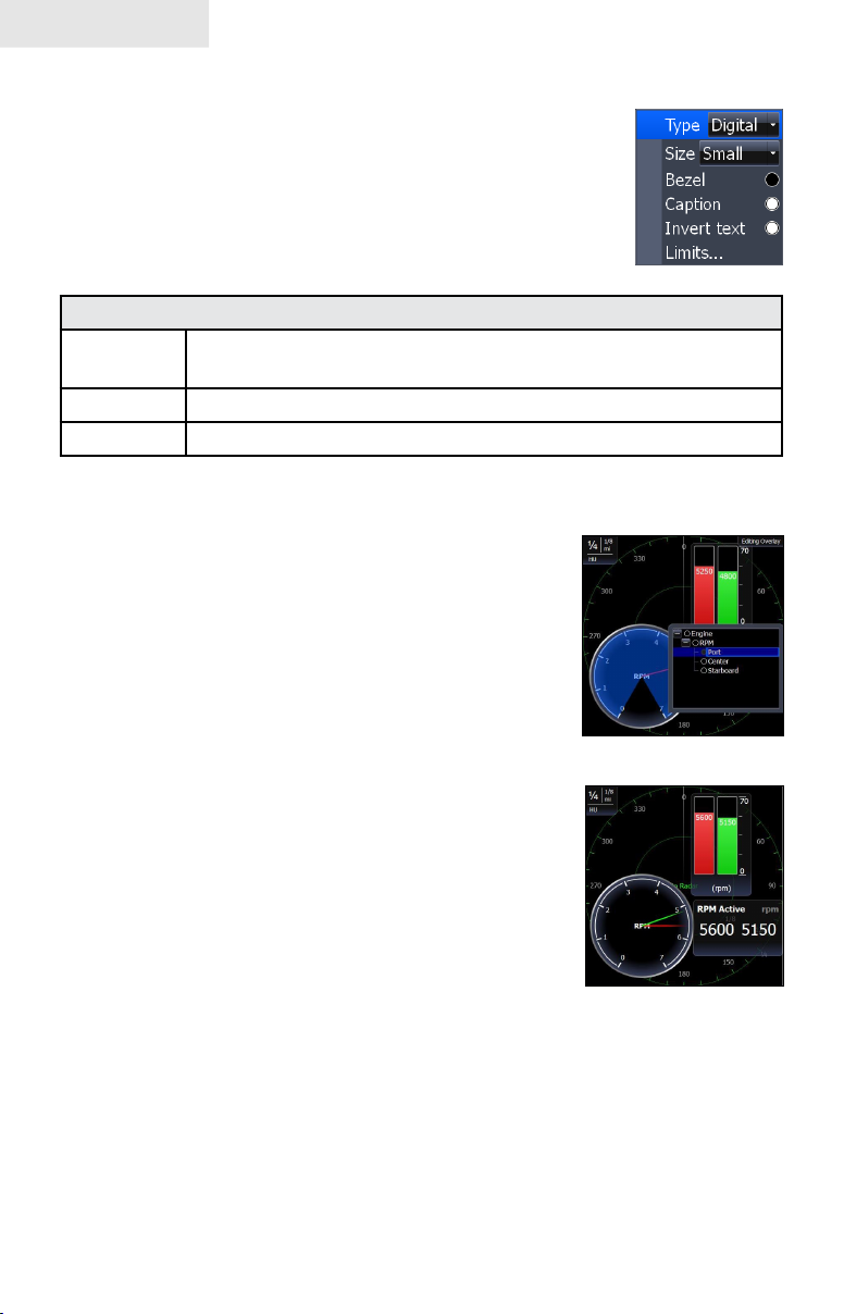
Add Source
Displays the same type of data from different sources on
the same analog gauge.
If, for example, you have multiple engines, you could
select port engine RPM as your data type and then display
starboard engine RPM using the Add source command.
Adds a bezel to the data overlay gauge, making it easier to
see against certain backgrounds
Both data sources could be displayed simultaneously on
an analog gauge with two needles; one dedicated to each
source.
To use Add Source:
Select 1. Add Source from the Edit Overlay menu
and press ENTER. The Add source menu will
appear.
Highlight a category a press 2. ENTER. A list of
subcategories will appear.
Select the desired subcategory and press 3.
ENTER.
To remove add source data:
Highlight1. Remove source from the Edit Overlay menu and press
ENTER. A list of sources will appear.
Select the source you want to remove and press 2. ENTER.
14
Add Source menu
Analog gauge
showing RPM from
two engines.
Page 17
Pages
Chart Page
Consists of a Map that moves in real time as you move. By default, the map is
shown from a birds-eye view with North at the top of the screen.
This page has three map orientation options (North Up, Track Up & Course Up) and
two ways to view the map: 2D and Shaded Relief (only available on select models).
The cursor is used to scroll the map, select objects and nd the distance between
objects. The Chart page is covered in more detail in the Chart Operation section.
On the Chart Page you can:
Save Waypoints•
Find points of interest (POI)•
Navigate routes; navigate to cursor and waypoints•
To access the Chart page, use the keypad to highlight Chart on the Pages menu and
press ENTER to access the Chart Page.
15
Page 18
Pages
Radar Page
Displays the PPI (Position Plan Indicator)
screen, Range Rings and the cursor.
The PPI can be shifted to show more of a
desired portion of the screen (Look Ahead,
Center & Offset) and the color palette
can be changed to show returns in white,
yellow, black or green. The radar page
is covered in more detail in the Radar
Operation section.
On the Radar Page you can:
Overlay compass data, range rings and EBL/VRMs on display•
Choose screen orientation from Head Up, Course Up & North Up•
Make radar targets more visible via Target Expansion•
Use the keypad to highlight Radar on the page screen and press ENTER to access
the Radar Page.
NOTE: You will only be able to see the Radar page if your unit
is connected to a radar.
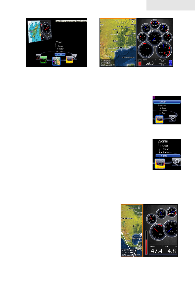
Info Page
Consists of multiple gauges — Analog, Digital
and Bar — that can be customized to display
selected data. Customizing the info page allows
you to monitor several types of desired data at
the same time.
On the Info Page you can:
Select data to be displayed in analog gauge or digital formats•
Change the page layout using one of three templates•
Select the range (scale) of analog gauges •
To access the Info Page, use the keypad to select Info on the pages screen and press
ENTER.
16
Page 19
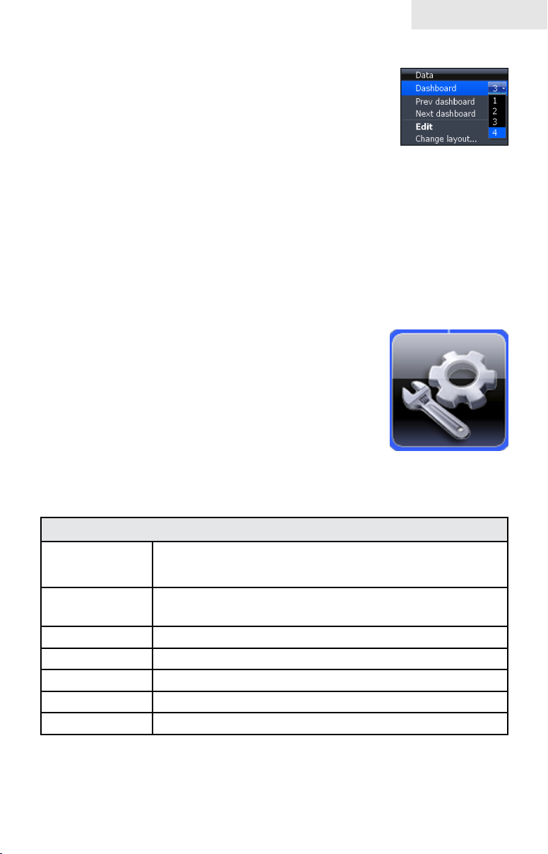
Data menu
Controls Info page data, page layout and data display format
selection. To access the Data menu, press MENU while on the
Info page.
Pages
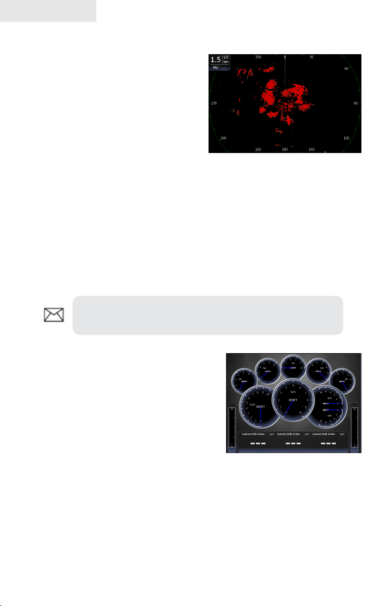
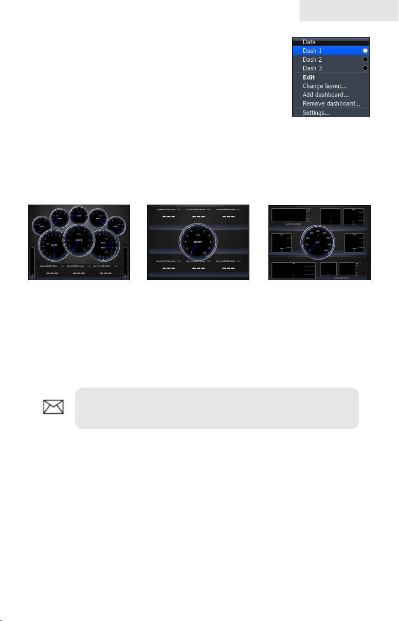
Dash 1, Dash 2 and Dash 3
Data menu
Info Page dashboard templates that vary in page layout and in the
number of gauges supported. The templates save you time by allowing you to use the
Info page without having to manually set up a gauge layout.
Gauge Layout Templates
General Engine
Layout
Digital Layout
Bar Layout
You can change the gauge layout of Dash 1 (General Engine Layout), Dash 2 (Digital
Layout) and Dash 3 (Bar Layout) templates using the change layout command. To
select a dashboard template, highlight the desired template on the Data menu and
press ENTER.
NOTE: You can toggle through the dashboard templates on the
screen by pressing the keypad left/right.
Edit
Used to select information displayed on the Info page. To switch the screen to Edit
Mode, select Edit from the Data menu and press ENTER. The active gauge will be
shaded in blue (analog) or surrounded by a blue border (digital and bar).
17
Page 20
Pages
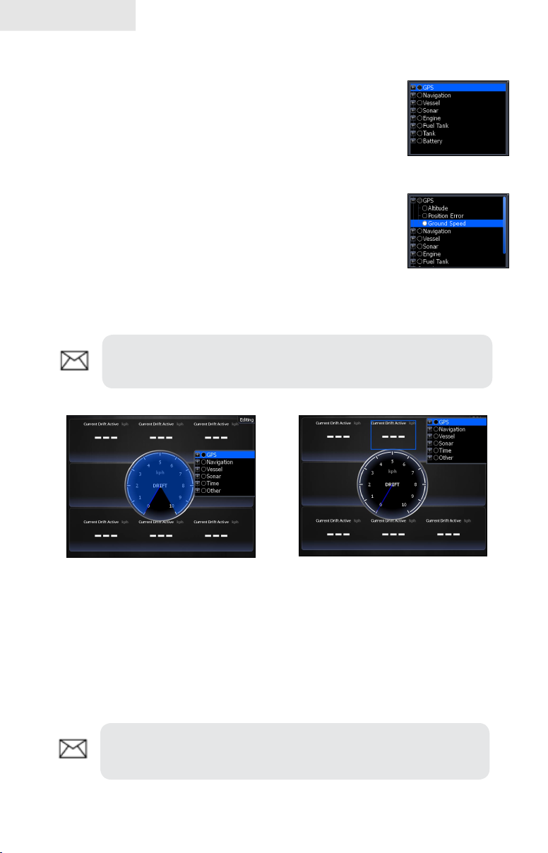
To edit gauge display:
Use the keypad to select the gauge you want to 1.
edit and press ENTER. The Select Data menu
will appear.
Use the keypad to select a data category and press 2.
ENTER. A list of subcategories will appear.
Select the desired subcategory and press 3.
ENTER.
Press 4. MENU. The Edit Data menu will appear.
Highlight 5. Finish Edit and press ENTER. The
Finish Edit Data menu will appear.
Highlight the 6. Save button and press ENTER.
NOTE: Press ENTER or EXIT to switch gauges into Edit Mode
GPS category
Ground Speed
subcategory
to Normal Mode.
Editing data on an analog
gauge
Editing data on a digital gauge
Edit Data menu
Changes Info Page gauge data, allowing you to display desired data on analog ,
digital and bar gauges. It also controls gauge limits.
To access the Edit Data menu, switch the screen to Edit mode and press MENU.
NOTE: Select Data, Add Source and Congure Limits are
described in more detail in the previous Data Overlay segment.
18
Page 21
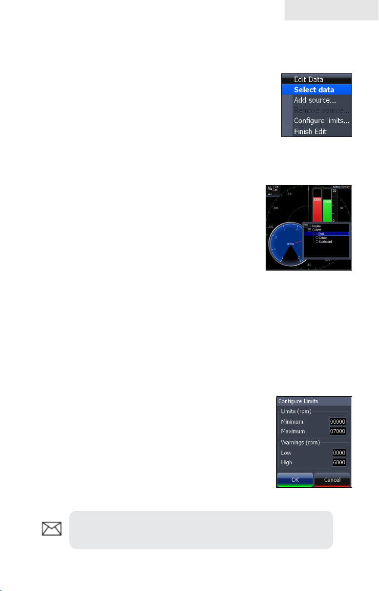
To select data:
Highlight 1. Select Data from the Edit Data menu and press ENTER.
The Select Data menu will appear.
2. Use the keypad to select the desired category
and press ENTER. A list of subcategories will
appear.
Select the desired subcategory and press 3.
ENTER.
To add source:
Select1. Add Source from the Edit Data menu
and press ENTER.
Use the keypad to select the desired category 2.
and press ENTER. A list of subcategories will
appear.
Select the desired subcategory and press 3.
ENTER.
Pages
To remove a source:
Highlight 1. Remove Source from the Edit Data menu and press ENTER.
The Remove data-source window will appear.
Select the source you want to remove and press 2. ENTER.
To Congure Limits:
Highlight 1. Congure Limits on the Edit Data menu
and press ENTER. The Congure Limits menu
will appear.
Select the desired text box and press 2. ENTER.
Use the keypad to enter the desired limit or 3.
warning threshold.
Select 4. OK and press ENTER.
NOTE: The Limits portion of the Congure Limits menu will
only be shown when conguring analog gauge limits.
19
Page 22
Pages
To Finish Editing:
Select 1. Finish Edit from the Edit Data menu and press ENTER. A
conrmation message will appear.
Select 2. Save and press ENTER.
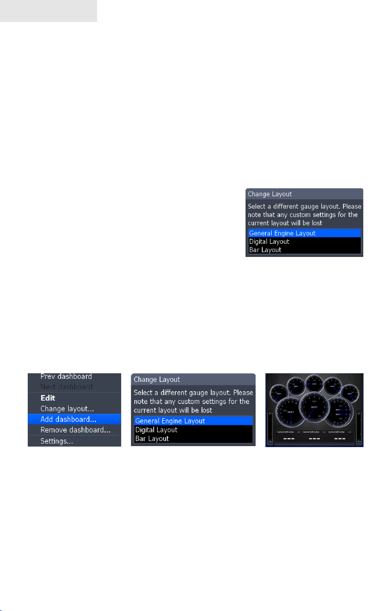
Change Layout
Controls the gauge layout of dashboard templates and customized dashboards. That
allows you to select a desired gauge layout template for all dashboards.
To change layout:
Highlight the desired dashboard and 1.
press ENTER.
Select 2. Change Layout from the Data
menu and press ENTER.
Use the keypad to choose a gauge 3.
layout template and press ENTER.
Add Dashboard
Allows you to customize and save multiple dashboard templates. Desired data can
be added to the gauges on each dashboard, allowing you to create custom dashboards
for a variety of shing conditions. You can even use the same gauge layout template
for each dashboard.
When you have created all desired dashboards, press the keypad left/right to toggle
through your dashboards.
To add a dashboard:
Select 1. Add Dashboard from the Data menu and press ENTER. The
Change Layout menu will appear.
Select the desired gauge layout and press 2. ENTER. Refer to the
previous Edit segment to customize the dashboard.
20
Page 23
Pages
To remove dashboards:
Select the number of the dashboard you want to 1.
delete from the numerical dashboard list.
Highlight 2. Remove Dashboard and press ENTER.
A conrmation message will appear.
Select 3. Delete and press ENTER.
Settings
Opens the Settings menu. Settings information is covered in detail in the Settings
menu section.
Numerical
dashboard list
Utilities
Allows you to set alarms, view sonar logs and access other
system settings.
To access Utilities:
Use the keypad to center the utilities icon on 1.
the screen.
Scroll down the list of utilities until the desired 2.
option is highlighted.
Press 3. ENTER.
Utilities Icon
Utilities
Waypoints,
Routes/Trails
Find
Alarms Access alarm history, status and change settings
Vessels View status and messages from vessels in the area
Sun/Moon Displays time when sun and moon will rise/set
Trip Calculator Keeps running tally/total of engine hours
Files Access, copy and delete data les and sonar logs
Access Waypoint, Route and Trails screen; covered in
the Chart Operation Section
Search for POIs, Vessels, Coordinates, Trails, Waypoints
and Routes; covered in Chart Operation Section
21
Page 24
Pages
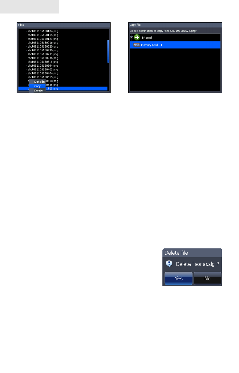
Copying a screenshot
To copy data les/sonar logs:
1. Highlight Files from the Utilities menu and press ENTER.
Select the desired File category and press the keypad to the right. A 2.
list of subcategories will appear.
Select a subcategory and press the keypad to the right. Highlight 3.
the desired data le/sonar log.
Press 4. MENU. Highlight Copy and press ENTER. The Copy File
screen will appear.
Select a place to copy the le, like an MMC card. Press 5. ENTER.
To delete data les/sonar logs:
Highlight 1. Files from the Utilities menu and press ENTER.
Select the desired File category and press 2. ENTER. A list of
subcategories will appear.
Select a subcategory and press 3. ENTER.
Highlight the desired data le. Copy and
Delete buttons will appear at the bottom of
the screen.
Copy File screen
Select the 4. Delete button and press ENTER. A conrmation message
will appear.
Select 5. Yes and press ENTER.
22
Page 25
Pages
Info selected as combo
display option
GPS/Info combo page
Displaying Combo Pages
You can display multiple pages at the same time by scrolling the
desired page’s icon to the center of the screen and then choosing a
secondary page from the list of combo page display options.
To display a combo page:
Use the keypad to select the rst page for the combo 1.
display. This is the primary page, which will be
displayed in the left panel.
Select another page from the primary page’s combo 2.
display list. This is the secondary page. It will be
displayed in the right panel.
Press 3. ENTER. The selected combo page will be
displayed.
Selecting an Active Page
When combo pages are displayed only one panel
can be active at a time. The panel outlined with
an orange border is the active page. You will only
be able to access the context menu of the active
panel. Pressing the MENU key will open the active
panel’s context menu.
Primary page
Secondary
page
To switch the active setting to the other panel, hold
down the PAGES key for 1 second.
23
Chart panel is active as
shown by the orange border
Page 26

Pages
Adjust Panel Sizes
Controls the size of panels when combo pages or
multi-panels displays are in use. Adjusting the size
of the panels, allows you to emphasize the panel
you want to see more clearly.
Panels can only be adjusted left/right, so
the panels on the side with the split view
can not be adjusted vertically.
To adjust panel sizes:
With the combo page or multi-panel display on the screen, press 1.
the PAGES key.
Press 2. MENU. Highlight Adjust Panel Sizes from the Data Overlay
menu and press ENTER.
Press the keypad left/right to adjust the panels to a desired size and 3.
press ENTER.
Adjust panel sizes selected
on the Data Overlay menu
24
Page 27
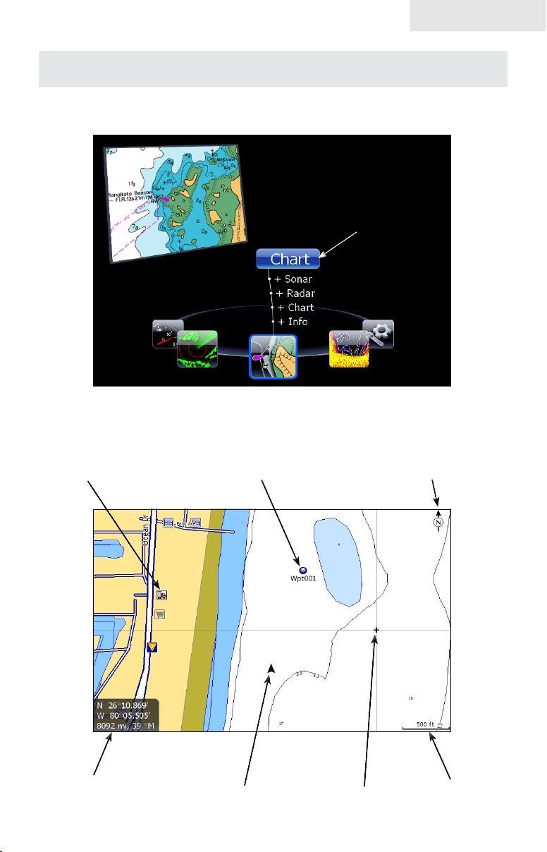
Chart Operation
Displaying the Chart page
Access the Chart page from the Pages menu.
Chart
To access the Chart
page, press the Pages
key to bring up the Pages
menu. Use the Arrow
keypad to select Chart
and press Enter.
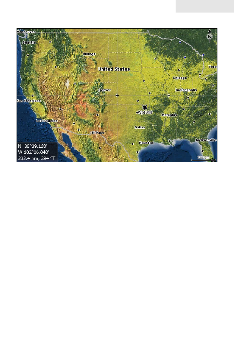
Chart page (2D Chart mode)
Point of Interest (POI)
Cursor coordinates
Current position icon
Waypoint
25
Chart orientation indicator
Cursor
Map scale
Page 28
Chart
The previous image shows some of the different items you will see when viewing
the Chart page:
• Point of Interest (POI): A position on the Chart page represented by
a symbol or character.
Cursor: • Used to view specic areas on the Chart page, select POIs,
create waypoints and measure distances. When the cursor is on-
screen, pressing the Exit key will toggle between the cursor's location
on the Chart page and your actual position. As long as the cursor is
on the Chart page your actual position may not be visible.
• Chart orientation indicator: Indicates the current direction the Chart
page is facing.
• Cursor coordinates: Displays the coordinates of the cursor on the
Chart page.
Waypoint: • An electronic address based on the latitude and longitude
of a selected Chart location.
• Map Scale: Represents the relationship between the distance on
the Chart page and the real distance on the earth's surface.
Current position icon:• Represents your current position.
Find Current Position
Power on the unit and display the Chart page. The current position icon represents
your current position on screen. The icon always points to your heading. If the cur-
rent position icon displays a question mark then the unit has not achieved
a satellite lock and is not tracking your current position. When sufcient
satellites are received to determine a position, the icon's movement will
correspond with your movement.
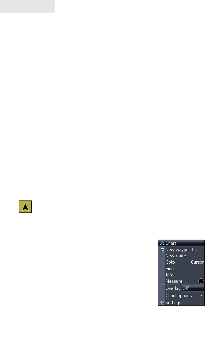
Chart menu
Use the Chart menu to adjust settings and enter commands.
From this menu you have access to routes, waypoints,
info, chart options and screen settings. To open the Chart
menu, go to the Chart page and press the MENU key. The
following features are listed in the order they appear on the
Chart menu, top to bottom:
New Waypoint:• Creates a new waypoint.
New Route: • Creates a new route.
Go to Cursor: • Navigates to the cursor position
on the Chart page.
Chart menu
26
Page 29
Find: • Opens the Find menu. From the Find menu you can search for
items by select categories.
Info: • Shows a list of items close to the cursor.
Measure: • Used to measure the distance between current position
and another point on the Chart page or between two different points.
Overlay: • Toggles radar overlay overlay on or off.
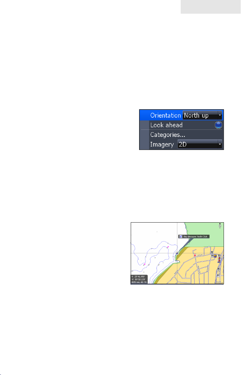
Chart options: • Opens the Chart options submenu which contains
the Map Orientation, Look Ahead, Chart categories and Imagery features.
Map Orientation controls the way the Chart
page moves in relation to your movement. The
Map Orientation settings are North Up, Heading Up and Course Up.
Look Ahead increases the view of your track.
Chart
Chart categories opens the Chart Categories
screen.
Imagery selects between 2D and Shaded Relief
mapping (only available on select models).
Settings: • Opens the Settings menu.
Chart options submenu
Selecting POIs on Chart page with Cursor
To select a Chart page POI:
From the Chart page use the 1.
Arrow keypad to center the
cursor over a POI. A pop-up
box will appear describing the
POI. The POI's coordinates are
displayed in the lower left hand
corner of the Chart page.
27
Page 30
Chart
Waypoints
A waypoint is the latitude and longitude of a specic position on the earth's surface.
You can quickly create a waypoint at your current position or you can create a waypoint at the cursor's position on the Chart page. You also can create a waypoint at
any location by manually entering the position's latitude and longitude.
Waypoints are important because they can be saved in the unit and later used to nd
your way back to a specic location, such as a favorite shing spot or an important
geographical feature. To quickly save a waypoint at the vessel's current position
press the WPT/FIND key.
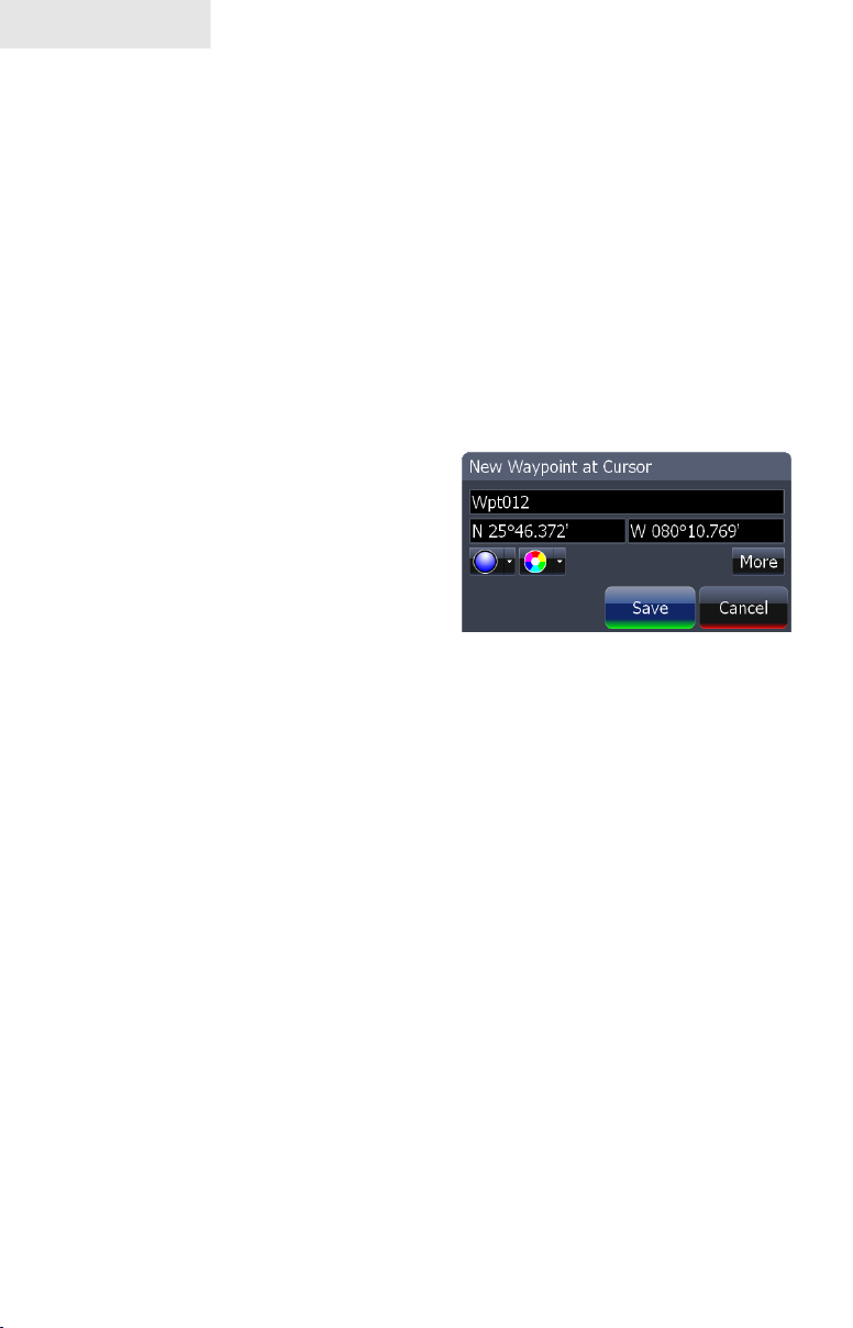
Create/Delete Waypoint from Chart page
To create a Waypoint at the Cursor's position on Chart page:
Place the cursor on the Chart 1.
page where you want to set the
waypoint and press ENTER
twice. The New Waypoint
menu will appear.
Select 2. Save from the New
Waypoint menu.
New Waypoint at Cursor menu
To create a Waypoint at the Vessel's
position on Chart page:
Press the 3. MENU key. From the Chart menu select New Waypoint.
When the New Waypoint at Vessel menu appears, select 4. Save.
28
Page 31

Chart
To Navigate to a Waypoint from the Waypoints screen:
From the Pages screen select 1. Waypoints, routes, trails, press ENTER.
When the Waypoints screen appears select the waypoint you want to
navigate to from the waypoints list and press MENU. The Waypoints
screen menu will appear. From the Waypoints screen menu select
Go to.
Waypoints screen
To view stored waypoints go to the Waypoints screen in the Utilities page. From the
Waypoints screen you can view and edit stored waypoints.
Waypoint name
Waypoint icon
Waypoint latitude
and longitude.
Time and date the
waypoint was created.
29
Page 32

Chart
Waypoints screen menu
To open the Waypoints screen menu, press
the MENU key from the Waypoints screen.
The following features are listed in the
order they appear in the Waypoints screen
menu, top to bottom:
Edit:• Opens the Edit Waypoint
menu.
New:• Opens the New Waypoint
menu.
Show:• Shows the Waypoint on the Chart page.
Go to:• Select to navigate to the waypoint.
Delete:• Deletes selected waypoint.
• Sort: Controls how waypoints are sorted in the Waypoints screen
list.
Delete All: • Select to delete all waypoints.
Find:• Use to search for waypoints in the Waypoints screen.
Waypoints screen, Search for Waypoint by name
If the waypoint list contains too many waypoints to search through manually, you
can search for a specic waypoint by name.
To Search for Waypoint by Name:
From the Waypoints screen 1.
press the MENU key. The
Waypoints screen menu will
appear.
From the Waypoints screen 2.
menu select Find. A keypad
will appear. Use the keypad to
enter the name of the waypoint
you are searching for and press
OK.
30
Page 33

Waypoints screen, Sort Waypoints
feature
You can choose how waypoints are sorted in
the Waypoints list by selecting Sort from the
Waypoints screen list menu. Waypoints can be
sorted by Name, Nearest or Icon. By default the
unit stores waypoints by name.
Waypoint Information screen
When a waypoint is saved to the Chart page, you
can view detailed information about that saved
waypoint.
To view waypoint information:
Place the cursor over the waypoint 1.
and press the MENU key.
Select 2. Info and press ENTER.
Chart
Editing a Waypoint on the Chart page
To Edit a Waypoint from the Chart page:
Place the cursor over the waypoint and press the 1. ENTER key. The
Edit Waypoint menu will appear.
Edit Waypoint menu
The Edit Waypoint menu is used to edit waypoint
settings and coordinates. Use this menu to change
the name, icon, color and description of a waypoint.
Edit Waypoint, More options:
Select More from the Edit Waypoint menu and
the following edit options will appear:
Name:• Edit the name of a waypoint.
Position:• Enter a latitude or longitude for a waypoint.
Icon:• Select a different waypoint icon.
31
Page 34

Chart
• Description: Input additional way-
point information.
Display: • Choose how a waypoint will
be displayed on Chart page.
Depth: • Select waypoint depth.
• Alarm Radius: Input distance that
sounds alarm when near a specic
waypoint.
Delete:• This will delete a waypoint.
Save:• Saves your waypoint changes.
Cancel:• Cancels any waypoint changes.
Edit Waypoint name, description, position or depth
To Edit Waypoint name or description:
From the Edit Waypoint menu, select 1.
the Name or Description text box
and press ENTER. The Waypoint
keypad will appear.
Use the keypad to enter the desired 2.
waypoint name and select OK.
To Edit Waypoint position:
From the Edit Waypoint menu select the 1.
latitude or longitude text box and press
ENTER.
Use the Arrow keypad to input the desired 2.
latitude or longitude and select OK.
To Edit Waypoint depth or alarm radius:
From the Edit Waypoint (More) menu select the Depth or Alarm 1.
radius text box and press ENTER. A numerical keypad will appear.
Use the keypad to input the desired depth or alarm radius and press 2.
ENTER.
32
Page 35

Chart
Edit Waypoint icon and color
You can change the default waypoint icon and color from the Edit Waypoint menu.
Edit Icon menu
Use the Edit Icon menu and Edit
Icon Color menu to change the
appearance of icons on the Chart
page.
Icon color palette
Routes
Routes make it easier to plan trips to desired destinations and backtrack to a previous
location. A route is a series of waypoints linked together to mark a course of travel. A
route must have at least two waypoints. The route segment between two waypoints
is called a leg.
The legs of a route are based on straight lines between waypoints. A route gives you
the ability to navigate to several waypoints in an ordered sequence without having
to manually select the next waypoint in the series.
Create Route from Chart page
To create a new route open the Chart menu and select New Route. You can use the
cursor on the Chart page to create a route.
To Create a New Route from the Chart page:
Press the 1. MENU key and select New Route from the Chart menu,
press ENTER.
Move the cursor to the start of the route and press 2. ENTER to set
the rst waypoint. Move the cursor to the next location and press
ENTER to set a second waypoint
33
Page 36

Chart
Repeat Step 2 until you have set all the desired waypoints along 1.
the route.
Press the 2. MENU key to open the Edit route menu. Select Save and
press ENTER. The route will be saved to the Routes screen.
From the Routes screen highlight the route and select 3. Start. The
Start Route message box will appear, select Forward.
34
Page 37

Chart
Routes screen
To view stored routes go to the Routes screen in the Utilities page. From the Routes
screen you can view and edit stored routes.
End of route
Route name
name.
Route length
Start of route
name.
Number of legs
in route.
Routes screen menu
From the Routes screen menu you can create a new route, edit a route or start a
route. To open the Routes screen menu, from the Routes screen, press the MENU
key. The following features are listed in the order they appear in the Route screen
menu, top to bottom:
Edit:• Opens the Edit Route screen.
New:• Opens the New Route
screen.
Show:• Shows the Route on the
Chart page.
Start:• Select to start navigating a
route.
Delete:• Deletes a selected route.
Delete All:• Deletes all routes in the
Route screen.
Find:• Use to search for routes in the Routes screen.
35
Page 38

Chart
To Edit Route:
From the Routes screen select 1.
the route to be edited and press
ENTER. The Edit Route screen
will appear.
From the Edit Route screen you 2.
can edit the route name, display
and waypoints in the route.
Use the Arrow keypad to select 3.
which route feature you want to
edit and press ENTER.
To Display / Hide Route:
From the Routes screen select the route from the routes list, press 1.
ENTER. The Edit Route screen will appear.
Highlight the Display check box and press 2. ENTER to either Display
or hide the route from the Chart page.
To Insert, Edit or Remove Waypoints from a Route:
1. From the Routes screen select a route from the route list, press
ENTER.
Edit Route screen
2. The Edit Route screen will appear.
Select a waypoint from the Waypoint
list, press MENU. A small submenu
will appear with the options: Insert,
Edit and Remove.
Select 3. Insert and press ENTER to
insert a waypoint into the route. To
remove a waypoint select Remove.
Selecting Edit will bring up the Edit
Waypoint dialog.
To Navigate Route from Routes screen:
S1. elect the route you want to navigate and press MENU. The Routes
screen menu will appear.
Select 2. Start from the Routes screen menu The Start Route dialog
will appear. Select Forward to navigate the route forward or Reverse
to navigate the route in reverse.
36
Page 39

Chart
To Search for Route by Name:
From the Routes screen press 1. MENU. The Routes screen menu
will appear.
From the Routes screen menu select 2. Find. A keypad will appear.
Use the keypad to enter the name of the route you are searching for
and press OK.
Trails
A trail is a record of the path you have traveled. Trails not only show you where you
have been, they can be used to retrace your path back to your starting point. On the
Chart page a trail is presented by a solid line extending from the back of the current
position icon.
From the factory, the unit is automatically set to create and record a trail when the
unit is turned on and you are navigating. The unit will continue to record a trail until
the trail length reaches the maximum trail point setting.
When the unit reaches the maximum trail point number it will automatically begin
recording the trail over itself. By default, the unit places a dot (trail point) on the
Chart page every time you change course.
Trails screen
To view stored trails go to the Trails screen in the Utilities page. From the Trails
screen you can view and edit stored trails.
Trail name
Indicates if Trail is displayed
on Chart page.
Trail color
Number of Trail
points.
Indicates if Trail is
being recorded.
37
Page 40

Chart
Trails screen menu
From the Trails screen menu you can create a new trail, edit a trail or delete a trail.
To open the Trails screen menu, press the MENU key from the Trails screen. The
following features are listed in the order they appear in the Trails screen menu, top
to bottom:
Edit:• Opens the Edit Trail
menu.
New:• Opens the New Trail
menu.
Show:• Brings up the Chart
page and shows the trail.
Display: • Select or deselect to
display or not display trail on
Chart page.
Record:• Select or deselect to
actively record a trail.
Delete:• Deletes a selected trail.
• Delete All: Select to delete all trails.
Trails screen menu
Find:• Use to search for trails in the Trails screen.
New Trail menu
You can edit a trail from the New Trail menu or from the Edit Trail menu once a
trail is created.
To Create a New Trail:
1. From the Pages screen, select Utilities
and press ENTER. The Waypoints and
Routes screen will appear.
From the Waypoints and Routes 2.
screen select Trails. The Trails screen
will appear.
3. From the Trails screen, press MENU.
The Trails screen menu will appear.
From the Trails screen menu select 4. New, press MENU. The New
Trail menu will appear, select Save.
New Trail menu
38
Page 41

Chart
Edit Trail menu
The Edit Trail menu is used to edit trail settings and coordinates. Use this menu to
change the trail name, trail color and description of a trail.
To edit a Trail name:
From the Trails screen 1.
select the trail to be edited,
press ENTER. The Edit
Trail menu will appear.
From the Edit Trail menu 2.
you can edit the name of
the trail by selecting the
trail name box and pressing
ENTER. The Edit Trail
name keypad will appear.
Use the keypad to enter
the desired trail name and
select OK.
Edit Trail menu
Trail line Color options
You can change the default trail line color from the Edit Trail More menu by selecting the Trail line color palette option.
Trail line color
palette menu
NOTE: If you record several overlapping trails, changing
the color of the different trail lines is a good way to keep them
separate when viewing them on the Chart page.
39
Page 42

Chart
Measuring Distances on Chart page
Use the Measure feature from the Chart menu to measure distances between yourself and another location on the Chart page or between two different points.
To select/deselect Measure feature:
From the Chart page press the 1.
MENU key. The Chart menu
will appear.
From the Chart menu select 2.
Measure.
When the cursor is on screen 3.
the cursor coordinates window
will display distance from your
position to the cursor position
on the Chart page.
To measure distance between two different points on the Chart 4.
page, place the cursor over a point and press ENTER, an X will
appear on the Chart page. Distance will be measured from the X on
the Chart page to wherever the cursor is placed on screen.
Search by Coordinates
To search for Chart page POI using coordinates:
From the Chart page press the 1.
MENU key. The Chart menu will
appear, select Find. The Find
menu will appear.
From the Find menu select 2.
Coordinate. The Find Coordinate
keypad will appear. Use the
keypad to enter the desired
coordinates and select OK.
Find Chart item
To search for specic Chart page item:
From the Chart page press the 1. MENU key. The Chart menu will
appear, select Find. The Find menu will appear.
From the Find menu select 2. Chart Items. The Find - Chart Items
screen will appear. Select Name, a keypad will appear. Use the
keypad to enter the name of the chart item and select OK.
40
Page 43

Chart
To view a list of specic Chart POI search options select Category from the
Find - Chart Items screen. A drop down list will appear. Select the specic
category from the drop down list.
Map Orientation
To change Chart page orientation:
From the Chart page press the 1. MENU key. The Chart menu will
appear, select Chart options. The Chart options submenu will
appear.
From the Chart options submenu select 2. Map Orientation. The three
Map Orientation options are: North Up, Heads Up and Course Up.
• North Up — Displays the Chart page
with North always at the top of the
screen.
Heads Up• — Displays the Chart page
in the direction the boat is facing.
• Course Up — Displays the Chart
page at the same orientation as your
initial bearing to a destination.
Look Ahead
Keeps your current position at the bottom of the Chart page to display more map
area in front of you.
To select / deselect the Look Ahead feature:
From the Chart page press the 1. MENU key. The Chart menu will
appear, select Chart options. The Chart options submenu will
appear.
41
Page 44

Chart
From the Chart options submenu select or deselect 2. Look Ahead to
turn this feature on or off.
Chart categories
Use the Chart Categories screen to control what you want to see on the Chart page.
To select / deselect Chart Categories:
From the Chart page press 1. MENU.
The Chart menu will appear; select
Chart options. The Chart options
submenu will appear.
From the Chart options submenu 2.
select Chart categories. The Chart
Categories screen will appear.
Select or deselect the chart options
you want to display on screen.
2D and Shaded Relief
(Shaded Relief only available on U.S. models)
To select between 2D and Shaded Relief:
From the Chart page press the 1. MENU key. The Chart menu will
appear. From the Chart menu select Chart options. The Chart options
submenu will appear.
From the Chart options submenu select 2. Imagery. The Imagery drop
down menu will appear with two map options: 2D and Shaded Relief.
Make your selection and press ENTER.
2D mapping
Shaded Relief, only available
on U.S. models.
42
Page 45

Chart
Chart page Icons, Tides and Currents
Use the cursor on the Chart page to view detailed information about selected icons,
including Tides and Currents.
The image, at left, shows a Current icon selected on the Chart page. To view
detailed information about an icon, press the MENU key then select Info from
the Chart menu. From the Chart Info screen, press Details.
Detailed information also can be viewed for Tide icons.
Radar Overlay
Places radar returns on top of the map.
That gives you greater awareness of your
surroundings by allowing you to see radar
returns aligned with actual radar targets.
To turn on radar overlay:
Highlight 1. Overlay on the Chart
menu and press ENTER.
Select 2. Radar and press
ENTER.
43
Radar Options menu
Page 46

Chart
Radar Options
The Radar Options menu appears when Radar Overlay is tuned on. It allows you to
customize the radar overlay settings from the Chart Page.
To access the Radar Options menu, select Radar Options from the Chart menu and
press ENTER.
Radar Options menu
Radar State Selects radar transmission mode
Adjust
Auto Gain
Sea Clutter
Transparency
Adjusts Gain, Sea Clutter, Rain Clutter, Interference
Rejection and Target Boost
Automatic Gain setting that is suitable for a variety of
conditions
Selects Sea Clutter setting from auto (harbor, offshore)
and manual settings.
Controls the transparency of radar overlay on the map To
make adjustments, highlight Transparency and press the
arrow keys left/right
NOTE: Radar State, Adjust, Auto Gain and Sea Clutter are
covered in more detail in the Radar Operation section.
Navionics
Your unit offers an unprecedented level of 2D and 3D mapping detail and numerous
mapping options, including Navionics chartcards. Navico mapping data is displayed
by default.
To view Navionics data:
Insert your Navonics card in the unit's MMC/SD card slot. 1.
Press 2. MENU twice, select Chart and press ENTER.
Highlight 3. Chart data and press ENTER.
Select 4. Navionics and press ENTER.
NOTE: You can use Navionics Platinum, Gold, Silver, Clas-
sic and HotMaps chartcards with your HDS unit.
44
Page 47

Chart
Navionics Settings menu
Use to customize the way Navionics data will be displayed on the Chart page, allow-
ing you to adjust the features best suited for your shing conditions.
To change Navionics Settings:
Select 1. Chart options from the Chart menu
and press ENTER.
Highlight 2. Settings and press ENTER.
Select a setting and press 3. ENTER.
Highlight the desired option and press 4.
ENTER.
Navionics Settings
menu
Navionics Settings and Options
Safety Depth• — Allows you to display the depth areas corresponding to the
safety contour desired. Available options are:
Off: No depth area displayed.
Other numeric depth values: The areas with depths up to value selected
are displayed in shades going from darker blue (for lower depths) to lighter blue (for higher depths). The areas whose depths are over the selected
value, and therefore navigable under safety conditions, will be displayed in
white. The Dryline areas are displayed in green.
Contours Depth• — Used to select the display of depth contours.
NOTE: When Night mode is selected, depth areas are dis-
played from lighter blue (for lower depths) to darker blue
(for higher depths). Depth areas over the value set are dis-
played in black.
Available options:
-5m: display depth contours up to 5 meters (16 feet)
-10m: display depth contours up to 10 meters (33 feet)
-20m: display depth contours up to 20 meters (66 feet)
-All: all depth contours are displayed
45
Page 48

Chart
Texture Type• — Enables (on) or disables (off) the 3D shading feature.
Photo overlay allows you to enable (full) or disable (off) the aireal photography overlay chart feature.
NOTE: These features are only applicable with Navionics
Platinum™ or Platinum Plus™ charts.
Annotation• — Allows you to display "Main" names (i.e. city names) only
or the "Full" set of names on the Chart page.
• Presentation Types — Is used for the selection of the symbols and colors
of the navigation chart "look and feel"; either U.S. or International "paper
chart" presentation types can be selected.
• Chart Details — This menu is used to select which object types and infor-
mation layers are displayed on-screen.
Available options:
Standard: Equivalent to standard display settings as defined in ECS regula-
tions.
All: Enables the display of all the object types and information layers on
the Chart page.
User: Allows selection of individual object types and information layers
on-screen.
46
Page 49

Radar Operation
Radar
Range Ring Size
Radar orientation indicator
To access the Radar Page:
North Indicator
Range Rings
Heading LineRange
Press the 1. PAGES key.
Use the keypad to select the 2. Radar Icon and press ENTER.
NOTE: You will only be able to see the Radar page if your unit
is connected to a radar.
Radar menu
Use the Radar menu to make adjustments to radar display
settings and features that not only change the appearance of
the display, but also make navigation easier.
To access the Radar menu, press the MENU key when the
Radar page is on the display.
47
Page 50

Radar
Radar State
Controls radar transmission modes: Off, Transmit and Standby. Off turns off the
radar. Transmit broadcasts a radar signal and standby leaves the radar on, but does
not broadcast a signal.
To select Radar State:
Press 1. MENU, highlight Radar State and press ENTER.
Select the desired state and press 2. ENTER.
NOTE: It can take 90 seconds or more to transition from Off
to Standby.
Adjust menu
From the Adjust menu you can make adjustments to Gain, Sea clutter, Rain clutter,
Interference rejection and Target boost.
To access the Adjust menu:
1. From the Radar menu select Adjust and press ENTER. The Adjust
menu will appear.
Highlight the desired setting and press the Arrow keypad left/right to 2.
make adjustments.
Gain
Controls the sensitivity of the radar receiver. Increasing gain
will show more detail on the screen; decreasing gain will show
less detail. Too much detail will clutter the screen. Conversely,
desired returns may not be shown if gain is too low.
Auto Gain
Selecting Auto gain from the Radar menu will automatically set the sensitivity of
the receiver to a level that works well under most conditions, reducing the need for
adjustments. If you make adjustments to the Gain level when Auto gain is on, Gain
will switch to manual mode.
To select Auto Gain:
Press the 1. MENU key. The Radar menu will appear
Select 2. Auto gain and press ENTER.
48
Page 51

Radar
Sea Clutter
Allows you to select the Sea Clutter adjustment mode — Auto or Manual. If you
make changes to Sea Clutter when it is in auto mode (Harbor or Offshore), Sea
Clutter will switch to Manual mode.
Sea Clutter Options
Manual Switches Sea Clutter from Auto to Manual mode
Harbor Auto setting optimized for harbor-like environment
Offshore Auto setting designed for offshore conditions
Rain Clutter
Precipitation reects radar signals, cluttering the screen. Interference Rejection
reduces or eliminates returns caused by rain, hail, sleet or snow.
Interference Rejection
Reduces interference from other active radars near your vessel. If another ship is
operating radar near you, interference from its radar signals can appear on your display. Increase interference rejection until radar interference is eliminated from your
display. Interference Rejection has four settings: Off, Low, Medium and High.
Target Boost (only available on some radars)
This feature increases the size of radar targets, making them easier to see on the
display. Target Boost has four options: Off, Low, Medium and High.
Clear Trails
Clears all target trails from the radar screen. New trails will continue to appear
unless you turn off the target trails feature.
To Clear Trails:
Press the 1. MENU key, the Radar menu will appear.
Use the Arrow keypad to select 2. Clear Trails and press ENTER.
49
Page 52

Radar
Position
You can move the PPI (Plan Position Indicator) to different locations on the radar
display. There are three Position options: Center, Look Ahead and Offset.
To change the PPI position:
Select Position from the Radar menu and press enter.1.
Select the desired position and press enter.2.
Position
Center
Look Ahead
Offset
Default setting, will position the PPI in the center of
the screen
Shifts the PPI to the bottom of the screen, allowing
you to see more of the area in front of your vessel
Allows you to move the PPI to a any location on the
display. If you shift the PPI to the right, you will see
more of what is to the left of your boat; if you move
the PPI forward you will be able to see more of the
area behind you
Center: PPI centered on the
display
Look Ahead: PPI moves down,
allowing you to see more of what
is in front of you
50
Page 53

Radar
Symbology on
Symbology off
Symbology
Used to turn on/off symbols displayed on the PPI screen, including range rings, range
markers and compass overlay. Rather than turn off each display feature individually,
the Symbology feature allows you to remove them all at once.
To toggle Symbology on/off highlight Symbology on the radar menu and press
enter.
EBL/VRM 1 EBL/VRM 2 EBL/VRM 1 & EBL/
VRM 2 Data Boxes
EBL/VRM
An Electronic Bearing Line (EBL) is a radial line used to show the distance of a
radar target to your vessel. A Variable Range Marker (VRM) is a range ring used to
measure the precise distance to a radar target. Selecting EBL/VRM from the Radar
Menu allows you to place up to two EBL/VRMs on the PPI display.
51
Page 54

Radar
EBL/VRM menu
Places selected Electronic Bearing Line and Variable
Range Marker on the display.
To select an EBL/VRM:
Press the 1. MENU key.
Use the keypad to select the 2. EBL/VRM and
press ENTER.
Use the keypad to move the EBL and increase/3.
decrease the size of the VRM. Press EXIT.
Adjust
Adjusts size and location of active EBL/VRM.
To adjust an EBL/VRM:
From the Radar menu highlight 1. EBL/VRM and press ENTER.
Select 2. Adjust and press ENTER.
Use the keypad to make adjustments to the EBL/VRM. Press 3. EXIT.
EBL/VRM menu
Data Box
Turns on/off on screen EBL/VRM information
box.
To turn on/off the EBL/VRM information box,
highlight Data box on the EBL/VRM menu and
press ENTER.
52
Data box
Page 55

Radar
Cursor position window
When the cursor is active on screen the Cursor position window appears in the
bottom left corner of the Radar page.
Cursor position window
Radar Overlay
Radar Overlay places radar returns on top of
the map on the Chart Page.
That gives you greater awareness of your
surroundings by allowing you to see radar
returns aligned with actual radar targets.
More information on Radar Overlay is available in the Chart Operation section of
this manual.
53
Page 56

Radar
Blank page
54
Page 57

Settings
Settings Menu
The Settings Menu provides access to installation and advanced conguration
settings for your unit. To access the Settings menu, press MENU twice.
Settings Menu Options
System Fuel Vessels
Page Alarms Simulator
Chart (if applicable) Trails Sirius (if applicable)
Radar (if applicable) Units
Sonar (if applicable) Network
System
Used to change system settings like units, language
and key beeps.
To access the System menu:
1. Press MENU twice.
Highlight 2. System and press ENTER.
System Menu
Language
Selects the language used on menus and dialog boxes. The default language is
English.
To select a language:
Select 1. Language from the System menu and press ENTER.
Highlight the desired language and press 2. ENTER. A window will
appear indicating the unit must restart to switch languages.
Select 3. Yes and press ENTER. The unit will restart.
Text Size
This unit will display text in two sizes: Small and
Normal. The Text Size menu allows you to select
the size of menu text.
55
Page 58

Settings
To change Text Size:
Highlight 1. Text Size from the System menu and press ENTER.
Use the keypad to select the desired text size and press 2. ENTER.
Key Beeps
By default, a tone (key beep) will sound when
any key is pushed on the unit. You can change
key beep volume or turn them on or off from the
Key Beep menu.
To change Key Beep settings:
Highlight 1. Key Beeps on the System menu and press ENTER.
Select the desired setting and press 2. ENTER.
Key beeps turned on
Time
Used to change local time to offset differences in time zone and to select the way
time and date will be displayed.
To set Time or Date format:
Highlight 1. Time on the System menu and press ENTER. The Time
menu will appear.
Select the Time format or Date format 2.
dropdown menu and press ENTER.
Use the keypad to select the desired 3.
format and press ENTER.
Highlight 4. OK and press ENTER.
To set Local Time:
Select 1. Local Time on the Time menu and press the keypad left/right
to select the desired offset.
Highlight 2. OK and press ENTER.
56
Page 59

Settings
Datum
A model of the earth’s surface based on a network of surveyed ground features
(points). This unit’s default datum is WGRS-84.
To select a Datum:
Select 1. Datum from the Chart settings menu and press ENTER.
Use the keypad to select the desired datum. Press 2. ENTER.
Coord System
Controls the coordinate system used when position coordinates are entered and
displayed.
To change Coordinate System:
Select 1. Coord System from the Chart settings
menu and press ENTER.
Highlight the desired option and press 2.
ENTER.
Magnetic Variation
Converts magnetic north data to true north, increasing the accuracy of navigation
information. The Magnetic Variance Auto setting, automatically converts magnetic
north to true north. When using manual mode, you will have to input the magnetic
variance.
To change magnetic variation settings:
Highlight 1. Magnetic Variation on the System menu. Press ENTER.
Select 2. Auto or Manual and press ENTER.
57
Page 60

Settings
Satellites
Satellite Status
Monitors the location of satellites in view and the quality of the unit’s satellite lockon. The Satellite page has two display options.
The Satellite screen displays a circular graphic that shows where satellites are
located and a bar graph that monitors the strength of satellites within range of your
unit. Your unit is locked on to satellites shown with blue bars.
To access the Satellite screen select Satellites from the System menu and press
ENTER.
58
Page 61

Settings
Screen Capture
Saves images of your unit’s screen to your unit. That allows you to capture images
of everything from underwater structure and sh to routes, map areas and radar
targets.
To take a screen capture:
Select1. Screen Capture from the System menu and press ENTER.
Press the2. LIGHT/POWER key to capture the current screen. Repeat
this step take additional screen captures.
To save screen captures to MMC/SD card:
Select 1. Files from the Utilities list on the Pages
menu. Press ENTER.
Highlight 2. My Files and press the keypad to the
right. Select screenshots and press the keypad
to the right.
Select the desired screenshot. Press 3. MENU.
The screenshot menu will appear.
Select 4. Copy and press ENTER. The Copy File menu will appear.
Your MMC/SD card will be listed on the screen. Select your MMC/5.
SD card and press ENTER. You will be taken back to the list of
screenshots. Repeat Steps 3-5 to copy more screenshots.
Screenshot selected
Screenshot menu
Files selected on
Utilities list
MMC/SD card selected
59
Page 62

Settings
Restore Defaults
To switch the unit back to the settings it had when you purchased
it (default settings), use the Restore Defaults command. Reset
Defaults will reset the unit to default settings.
To Restore Defaults:
Highlight1. Restore Defaults on the System menu and press ENTER. A
conrmation message will appear.
Select 2. Yes and press ENTER. The unit will restart.
Advanced
A ne tuning adjustment for advanced users that allows duplicate waypoint names,
enables sticker backlight and slider hold off.
Advanced Settings menu (Enabling Flywheel scroll dial
setting is available only on HDS-8/10-inch units.)
To access Advanced Settings:
Select 1. Advanced on the Settings menu and
press ENTER.
Highlight a desired setting and use the right/left 2.
arrow keys to open (—) or close (+) the setting.
60
Page 63

Settings
To adjust Waypoint, Hardware, Flywheel and Radar settings :
Open the desired setting (—).1.
Highlight the setting information and 2.
press Enter to turn it on/off. The center
circle will be lled when the setting is
on; empty when it is turned off.
To adjust cursor settings:
Highlight the desired cursor setting and press 1. ENTER. A dialog box
will appear.
Use the arrow keys to select the desired value and press 2. ENTER.
About
Used to view your unit’s current software version. To check the unit’s software
version, highlight About on the System menu and press ENTER.
61
Page 64

Settings
Chart Settings Menu
Contains Chart settings ranging from display
options like Range Rings and Grid Lines to map
settings like Chart Data and Datum.
To access the Chart Settings Menu:
Press 1. MENU twice.
Highlight 2. Chart and press ENTER.
Chart Data
This unit can use mapping data from Navico and
Navionics. The Chart Data menu allows you to
select the desired map data (Navico 3D mapping
data available in US only).
To select chart data:
Highlight 1. Chart Data on the Chart
Settings menu and press ENTER.
Select the desired map data and 2.
press ENTER.
Chart Settings Menu
The Chart Settings menu
changes when Navionics is
the selected chart data type.
Range Rings
A navigation aid used to estimate distances.
Centered around your location, Range
Rings are placed a preset distance from
your location, allowing you to quickly
estimate distances while navigating.
To turn Range Rings On/Off, highlight
Range Rings on the Chart Settings menu
and press ENTER.
Range Rings
Heading Extension
A line extending from the front of the current position icon that is used to estimate
distance and time of arrival. The distance and estimated time of arrival is based on
the time interval selected from the Heading Extension menu.
62
Page 65

Heading Extension line
To use Heading Extension:
Highlight 1. Heading Extension from the chart menu and press
ENTER.
Select the desired time interval and press 2. ENTER.
NOTE: Range Rings and Heading Extension may not be
available in all chart data.
Popup Information
Turns on information windows that appear when
the cursor is centered on a point of information.
That allows you to identify POIs without having
to zoom in to see it on the screen.
To turn on/off Popup Information, highlight
Popup Information on the Chart Settings menu
and press ENTER.
Settings
Grid Lines
Displays base values for latitude and
longitude, making it easier to get a general
idea of your location on the latitude/
longitude scale.
To turn Grid Lines On/Off, select Grid
Lines from the Chart Settings menu and
Press ENTER.
Gridlines
Waypoints
Turns on/off waypoint display properties. When a large number of waypoints are on
the display, turning off waypoints will provide a better view of the map. To turn on/
off waypoint display properties, select Waypoints from the Chart menu and press
ENTER.
63
Page 66

Settings
Routes
Turns on/off route display properties. When several routes are on the display, turning
off routes will give you a better view of the map.
To turn on/off route display properties,
select Routes from the Chart menu and press
ENTER.
Trails
Turns on/off Trail display properties. When several trails are on the display, turning
off routes will give you a better view of the map.
To turn on/off trail display properties, select Trails from the Chart menu and press
ENTER.
Hide Chart
Removes mapping data from the display, making it easier
to view routes, waypoints and the cursor.
To turn on/off the map data, highlight Hide Chart on the
Chart Settings menu and press ENTER.
64
Hide Chart mode
Page 67

Settings
Radar Settings Menu
Controls Radar options and display settings like Target
Expansion, Orientation and Bearings.
To access the Radar settings menu:
Press 1. MENU twice.
Select 2. Radar and press ENTER.
Radar Settings
Target Expansion
Increases the size of radar targets, making them easier to see on the radar display. To
turn on/off Target Expansion, highlight Target Expansion and press ENTER.
Target Trails
Creates an onscreen history of the movement
of radar targets, making it easier to monitor
the direction and position of targets in relation
to your vessel.
Menu
To set Target Trails:
Highlight 1. Target Trails on the
Radar Settings menu and press
ENTER.
Use the arrows to select an 2.
interval and press ENTER.
Target Trails
Palette
Radar echoes can be displayed in black, white, green or yellow. The Palette feature
allows you to select the color that suits your viewing preferences.
To change the Palette:
Highlight 1. Palette on the Radar Settings menu and press ENTER.
Use the keypad to select the desired color palette and press 2.
ENTER.
65
Page 68

Settings
Black Color Palette
White Color Palette
Orientation
Controls the way the map moves in relation to the movement of your vessel. That
allows you to select a desired method for viewing your surroundings on the radar
display.
• Course Up — map stays at same orientation as the initial bearing to the
selected waypoint.
• Heading Up — unit keeps your heading at the top of the screen, regardless
of the direction you are traveling.
• North Up — North is always shown at the top of the screen.
To change Map Orientation:
Highlight 1. Map Orientation on the Radar
Settings menu and press ENTER.
Use the keypad to select the desired 2.
option and press ENTER.
Threshold
Controls the level of radar returns. That allows you to unclutter the display by
removing unwanted signals. The zero percent setting allows all To make adjustments,
select Threshold and press the keypad left/right.
North Indicator
The North indicator is shown on the outer circle of the radar display. To turn on/
off North Indicator, select North Indicator from the Radar Settings menu and press
ENTER.
66
Page 69

Range Rings
Allows you to quickly estimate the distance
from your vessel to a another radar target.
To turn on/off Range Rings, highlight Range
Rings on the Radar Settings menu and press
ENTER.
Range rings
Range Markers
Located below each Range Ring, Range
Markers display the distance from your position
to each range ring.
To turn on/off Range Markers, select Range
Markers from the Radar Settings menu and
press ENTER.
Compass
Settings
Range markers
A Compass overlay can be displayed on the background of the radar page. To turn
on/off the Compass overlay, select Compass and press ENTER.
Compass Overlay turned off Compass Overlay turned on
Bearings
Bearings allows you to choose if you want the direction you are headed to show
as True Magnetic (TM) or Relative (R). T/M or True/Magnetic will show your
direction based on magnetic north. R or Relative will show your direction based on
your relative heading.
67
Page 70

Settings
To set T/M or R:
Press 1. MENU twice.
Select 2. Radar and press ENTER.
Highlight 3. Bearings and press ENTER.
Use the arrows to select a bearing and press 4. ENTER.
Installation
Provides access to the Radar Installation menu.
Radar Installation menu
To access Radar Installation menu:
1. Press the MENU key twice.
2. Highlight Radar and press ENTER.
3. Select Installation and press ENTER.
Installation Adjustment Menu
The installation adjustment menu is used to make adjustments to bearing alignment,
range offset, antenna height and open array park angle.
When the installation adjustment menu is accessed, press the
keypad up/down to select a feature. Press the keypad left/right
to make adjustments to a selected feature.
Press EXIT to return to the Radar Installation menu. To remove
the Radar Installation menu from the screen, select Close and
press ENTER.
Adjustment Menu
68
Page 71

Settings
Bearing alignment
Used to align the bow of your vessel with the heading line (zero point). Bearing
alignment is also referred to as zero bearing.
To make adjustments to bearing alignment, switch the radar state to Transmit and set
radar orientation to Heading Up.
To select Heading up orientation:
1. From the Radar Page, press MENU.
2. Select Orientation and press ENTER.
3. Use the keypad to select Heading Up and press ENTER.
4. Press EXIT.
Before Bearing Alignment
Bow of ship is lined up with
the tip of a peninsula; the
bearing line is not.
To Adjust Bearing Alignment:
1. Line up the bow of your vessel with a stationary target (lighthouse,
pier, etc) at least 1 nm away
Select 2. Adjust Bearing Alignment from the Radar Installation menu
and press ENTER. The Installation Adjustment menu will appear.
Press the keypad left/right to rotate the radar image so the reference 3.
target is at 0° or 12 o’clock from the radar center.
After Bearing Alignment
Bearing line aligned with
peninsula, matching the
alignment of the bow.
69
Page 72

Settings
Range offset
Eliminates the time lag between real radar returns and the time it takes data to be
processed by the radar software. Range Offset is also referred to as zero range and
trigger delay.
Range Offset Sequence. The circle shrinks as range is increased.
To Adjust Range Offset:
Use the 1. ZOOM IN/ ZOOM OUT keys to set range to 1/8 nm.
Highlight 2. Adjust range offset from the Radar Installation menu and
press ENTER. The installation adjustment menu
will appear.
Press the keypad to the left set range offset to 0. 3.
Press ENTER.
If there is a blank, black circle around the center or 4.
a solid circle of color at the center, increase the range offset until the
circle disappears or almost disappears.
If you increase th range offset too far, decrease it until the circle 5.
appears again.
Antenna Height
Antenna height is the distance from the waterline to the Antenna (scanner). It is
important to correctly input antenna height to prevent problems with the Sea Clutter
feature.
To Adjust Antenna Height:
Select 1. Adjust Antenna Height from the Installation menu and press
ENTER.
Press the keypad left/right to input the distance from the antenna to 2.
the water surface. Press EXIT.
70
Page 73

Settings
Open Array Park Angle
When an open array antenna is turned off, the antenna’s momentum will cause it
to continue rotating before coming to a stop. Open array park angle allows you to
adjust the antenna’s parking angle so it will stop in a desired position.
To Adjust Open Array Park Angle:
Select 1. Adjust Bearing Alignment from the Radar
Installation menu and press ENTER. The
Installation Adjustment menu will appear.
Press the keypad left/right to enter a value that will 2.
cause the antenna to stop in the desired position.
Tune
You should not have to adjust Tune for the life of this unit. This feature is intended
for use by only trained technicians.
Reset Radar to Factory Defaults
Resets radar to factory default settings.
71
Page 74

Settings
Fuel
Used to input fuel data like engine/tank conguration,
fuel tank capacity and engine calibration. Your unit uses
that data to calculate the overall fuel performance of your
vessel. To access the Fuel menu, select Fuel from the
Settings menu and press ENTER.
Refuel
Controls engine calibration and is used to input the amount of fuel added to the
tank(s). Engines must be calibrated with your fuel tanks to get correct readings on
fuel economy, fuel used, etc.
Amount Added
window
Fuel menu
Amount
Added text
box: Input
amount of fuel
added here
Refuel menu
Set to Full
checkbox: Check
this box when you
ll up your tank
It is important to enter the amount of fuel added to your tank(s) each time fuel
is added. That ensures the correct fuel data is used in the unit’s fuel performance
calculations.
To input fuel added:
Select 1. Refuel from the Fuel menu and press ENTER.
Use keypad to select the Amount Added window and press enter. 2.
The Amount Added text box will appear.
Use the keypad to input the amount of fuel added and press 3.
ENTER.
72
Page 75

To set tank to full:
Highlight the 1. Set to full checkbox
on the Refuel screen and press
ENTER.
Highlight 2. OK and press ENTER.
The calibration options screen will
appear. You are
ready to calibrate.
To calibrate engine(s):
With the calibration options screen displayed, select the checkbox 1.
next to the engine you would like to calibrate .
Highlight 2. OK and press ENTER. The Calibration screen will
appear.
Settings
Tank set to full
Calibration options screen
Use the keypad to highlight the Actual amount used window and 3.
press ENTER.
Input the amount of fuel used in the Actual amount used dialog box 4.
and press ENTER.
Highlight the 5. Next button and press ENTER. The Conrm calibration
screen will appear.
After conrming calibration data, highlight 6. OK and press ENTER.
Calibration screen
73
Page 76

Settings
Fuel Used
Data information screen that displays fuel
consumption data including fuel used
since last ll up, fuel used on the current
trip and fuel used during a season.
To access fuel used information, select
Fuel Used from the Fuel menu and press
ENTER.
Highlight the Reset button and press
ENTER to set corresponding fuel data
values (trip and seasonal) to zero.
Vessel Setup
Controls vessel conguration, which includes selecting the number of engines/
fuel tanks and inputting the capacity of each fuel tank. Vessel Setup data must be
congured before you can calibrate your engine(s).
To access the Vessel Setup menu, highlight Vessel Setup on the Fuel menu and press
ENTER.
Fuel used screen
Vessel
conguration
menu: select
number of
engines and fuel
tanks here
Calibration
info button: get
calibration info
here
Tank size text
box: input
tank size here
Tank size
window
Vessel Setup
74
Page 77

Settings
Engine/Tank Conguration
Used to input the number of engines and fuel tanks on your vessel. Your unit must
have that information to be able to calibrate you engine(s).
To select engine-tank conguration:
Highlight the vessel conguration drop-down 1.
menu and press ENTER.
Select a engine/tank conguration and press 2.
ENTER.
Highlight the 3. Save button and press ENTER.
To input tank size:
Highlight the 1. Tank Size window and press ENTER. The Tank Size
Text box will appear.
Use the keypad to input the size of the 2.
selected tank and press ENTER.
Repeat Step 2 for each tank on your 3.
vessel.
Select the 4. Save button and press
ENTER.
Calibrate
Launches engine calibration information window
referring you to your fuel sensor’s installation
manual.
75
Page 78

Settings
Alarms
This unit has alarms covering everything from depth and water temp rate to fuel and
waypoint radius. The alarms list has three tabs: Active, History and Settings.
Active — used to view alarms that have been enabled•
History — shows log of alarm activity, which includes data like when •
alarms were triggered and when they were cleared
Settings — provides access to Alarms list, allowing you to enable •
alarms and set alarm limits
NOTE: Some alarms will not work unless a corresponding
sensor is connected to the unit or the network.
To enable/disable an Alarm:
Select 1. Alarms from the Settings menu and press ENTER.
Highlight 2. Settings and press ENTER.
Select the desired alarm from the alarms list and press 3. ENTER.
Displays list of
enabled alarms
Enabled
Alarm
Shows history of
Alarms List
alarm activity
76
Enable alarms and set
limits (thresholds)
Alarm Limits (Thresholds)
Page 79

Settings
To silence an alarm:
When an Alarm is triggered, a tone will sound and a alarm window will appear on
the screen. Press ENTER to silence the alarm and close the alarm window.
After alarm is silenced its corresponding alarm bell will continue to ash
in the bottom left corner of the screen. To remove the bell from the screen,
disable the alarm and then enable it again. The bell will not reappear unless
the alarm is triggered.
Set Limit
Sets thresholds (limits) that will trigger the alarm when met or exceeded. If a
threshold can be set for a particular alarm, the Set Limit button will appear at the
bottom of the screen when that alarm is highlighted on the alarm list.
To set alarm limit:
Highlight the desired alarm on the alarm 1.
screen and press MENU.
Select 2. Set Limit and press ENTER. The
Alarm Limit keypad will appear.
Input the desired alarm threshold and 3.
press ENTER.
Siren Enabled
When the Siren is enabled, a tone will sound when an
alarm is triggered. To enable alarm sirens, highlight
Siren Enabled on the Alarms menu and press
ENTER.
77
Set limit selected on Water
Temp Rate menu
Page 80

Settings
Trails
Controls the way trails are logged (updated).
Trails mark your movement as you travel,
placing points along your path using one of
three logging types: Time, Distance or Auto.
You can save up to 10 trails with up to 9,999
points per trail. If a trail exceeds 9,999 points,
each new point will overwrite a point at the
beginning of the trail.
Logging Type
Controls the method used for updating a trail. Trails can be updated using Time,
Distance or the default automatic setting.
Logging Types
Time
Distance
Auto
A point is placed along the trail after a selected amount of time
A point is placed along the trail after you travel a selected distance
A point is placed along the trail every time you change direction
Trails Menu
To select a Logging Type:
Highlight 1. Logging Type on the Trails menu and press ENTER.
Use the keypad to select 2. Auto, Distance or Time and press ENTER.
Distance Period
Controls how far you will travel before a point is placed along the trail.
To set Distance period:
Highlight 1. Distance Period and press
ENTER. The distance period keypad
will appear.
Input the desired distance and select 2.
OK. Press ENTER.
Distance Period set to 1nm
78
Page 81

Time Period
Controls how much time will pass before a point is placed along the trail.
To set Time Period:
Highlight 1. Time Period and press
ENTER. The distance period keypad
will appear.
Input the desired distance and select 2.
OK. Press ENTER.
Time Period set to 5 seconds
Units
Controls the unit of measure used for a variety of
data, ranging from distance and speed to heading and
barometric pressure. To access the Units menu, select
Units from the Settings menu and press ENTER.
To change a unit of measure:
Select a unit from the Units menu. Press 1.
ENTER.
Settings
Select the a unit of measure and press 2.
ENTER.
79
Page 82

Settings
Network
Controls network conguration, data sources, serial port
settings, waypoint sharing and allows you to monitor
network performance (NMEA 2000 and ethernet) and
network devices.
To access the Network menu, select Network from the
Settings menu and press ENTER.
Auto Congure
Resets all Data Sources to default settings
and removes all instances on networked
HDS units.
To auto congure a network:
Select 1. Auto Congure from the Network menu and press ENTER.
Highlight 2. Yes and press ENTER.
Data Sources
An advanced feature that allows you to use
data from a network data source or data from a
sensor connected to your unit.
Network menu
If, for example, you do not want to use your
unit’s internal GPS antenna, you could use an
external GPS antenna connected to an ethernet
or NMEA 2000 network.
To access the Data Source Selection Screen,
highlight Data Sources on the Network menu
and press ENTER.
To select a data source:
Select a data category and press the keypad to the right. A subcategory list 1.
will appear.
Select a subcategory and press the keypad to the right. A list of sources will 2.
be displayed.
Highlight a desired data source and press 3. ENTER.
80
Data Source Selection Screen
Page 83

Settings
Data Source menu
Allows you to change the name and scope of a source and add/remove sources
from a NMEA 2000 or ethernet network. To access a Data Source menu, highlight
a desired source and press MENU.
Rename
Used to rename a Data Source. That makes it easier to recognize one
data source from another when they are the same type of source.
To Rename a data source:
Select 1. Rename from the desired data source menu and
press ENTER. A keyboard will appear.
Input the desired name and select 2. OK and press ENTER.
New
Allows you to create a new instance of a data source.
To create new data source instance:
Select 1. New from the desired source menu and press ENTER. A keyboard
will appear.
Input the name of the new instance, select 2. OK and press ENTER.
Remove
Removes an instance from the Data Source Selection list.
To remove an instance, select Remove from the desired data source menu and press
ENTER. The data source is removed from the Data Source Select list.
Scope
Controls the way data source settings are shared/not shared on an ethernet network.
Scope lets you select a mode that allows data source settings to be shared by HDS
units on an ethernet network (Global).
You can also select a mode that allows each HDS unit to have individual data source
settings (Local).
Data Source
menu
Scope Settings
Global Local
Data source settings will apply to all
HDS units on an ethernet network.
Data source setting will apply only
to the unit with the local setting.
81
Page 84

Settings
To select a scope:
Highlight 1. Scope on the selected device’s data source menu and
press ENTER.
Use the keypad to select 2. Global or Local and press ENTER.
Reset Global and Reset Local
Selecting Reset Global will reset all the source selections to default settings and
removes all instances on all networked HDS units.
Reset Local is used to change all source selections on your HDS unit from Local to
Global.
To reset global or local sources:
Highlight Resset Global or Reset Local and press enter. A conrmation 1.
message will appear.
Select Yes and press enter. 2.
Device List
Displays a list of devices connected to a NMEA 2000 network.
From the Device List you can:
View device data•
Change the device instance•
Congure device alarms•
Congure devices•
Calibrate devices•
Enable/disable WAAS/EGNOS/MSAS for GPS antenna by conguring •
HDS iGPS
To access the device list, Select Device List from the Network menu and press
ENTER.
Device Menu
Controls the way data is displayed on the Device list. To
access the Device menu, highlight the desired device and press
MENU.
Device List
82
Page 85

Settings
Device Menu Options
Details Accesses the Device Information screen
Refresh Refreshes the device list
Sort Allows you to sort device list by Model ID or Serial No.
Conguring Devices
Devices have different conguration options. Name, tank size and location can
be congured on some devices; only the name can be congured on others. Some
devices like a fuel ow, can be calibrated from the device list.
Device List Device Information
Screen
To congure a device name or device tank size:
Select a device from the device list and press 1. ENTER. The Device
Information screen will appear.
Highlight the 2. Congure button and press ENTER. The Device
Conguration screen will appear.
Highlight the 3. Name or Tank Size text box and press ENTER. A keypad
will appear.
Use keypad to input the desired information. Select 4. OK and press
ENTER.
NOTE: For more information on device conguration refer to the
documentation that came with your device.
Device Conguration
Screen
83
Page 86

Settings
To congure device location:
Select a device from the device list and press 1. ENTER. The Device
Information screen will appear.
Highlight the 2. Congure button and press ENTER. The Device
Conguration screen will appear.
Highlight the 3. Location dropdown menu and press ENTER.
Select the desired location and press 4. ENTER.
Instance
You can change a device instance from the Device Conguration screen. This,
however, should only be attempted by a qualied technician.
Calibrating devices
Several devices can be calibrated from the devices list including Fluid Levels, Fuel
Flows and Trim Tabs. Every device that can be calibrated from the devices list, will
have a calibrate button on the Device Information screen. The calibrate button opens
the Device Calibration screen, which has onscreen calibration instructions for the
device.
Calibrate button
To access calibration instructions:
Select the desired device from the device list and press 1. ENTER.
Highlight the 2. Calibrate button on the Device Information screen and
press ENTER. Follow the onscreen calibration instructions.
NOTE: For more information on device calibration, refer to
the documentation that came with your device.
Calibration instructions for a
uid level
84
Page 87

Settings
Diagnostics screen: NMEA 2000
Diagnostics screen: UDB
Diagnostics
Displays diagnostic information on NMEA 2000 networks displays the status of
information shared between units (UDB). From the UDB tab, you also can select a
unit to be used as the master (primary) unit when sharing information.
To access the Diagnostics screen, select Diagnostics from the Network menu and
press ENTER.
NMEA 2000 receive/send waypoint
Turns on/off the unit’s ability to send and receive
waypoints across a NMEA 2000 network.
NMEA 0183 receive waypoint controls the
unit’s ability to receive waypoints over a
NMEA 0183 network.
NMEA 2000 receive waypoint
turned on
To turn on/off NMEA send/receive waypoint commands, highlight the desired
NMEA send/receive option and press ENTER.
85
Page 88

Settings
Serial Ports
Congures communication ports to send or receive data with another electronic
device, like an autopilot.
To congure serial ports:
Highlight 1. Serial Ports on the Network menu
and press ENTER. The Serial Settings
menu will appear.
Select the desired setting (Protocol, 2.
Communication Port 1 or Communication
Port 2) and press ENTER.
Use the keypad to select the desired option 3.
and press ENTER.
Highlight 4. OK and press ENTER.
NMEA 0183 Output
Controls NMEA 0183 sentences used, allowing you to select the type of messages
your unit will transmit when communicating with other NMEA 0183 devices. The
default setting will work well under most conditions.
To access NMEA 0183 Output screen:
Select 1. NMEA 0183 Output from the
Network menu and press ENTER.
Highlight a desired sentence and press 2.
ENTER to turn it on/off.
To nalize changes, select 3. OK and
press ENTER.
Serial settings menu
NMEA 0183 Output screen
86
Page 89

Vessels
Controls settings used to monitor vessels in your
area with an AIS receiver. The Vessels feature
makes it easier to navigate safely through high
trafc areas.
To access the Vessels menu, select Vessels from the
Settings menu and press ENTER.
MMSI (Maritime Mobile Service Identity)
Used to input your MMSI number into the unit.
To input MMSI number:
Highlight 1. MMSI on the Vessels menu
and press ENTER.
Use the keypad to input the MMSI 2.
number and press ENTER.
Settings
Vessels Menu
Display
Allow you to select what vessels will be shown on the display. That helps you
customize the screen so you can view only desired vessels.
Display options
All Displays all vessels in the area around your vessel
None Eliminates all vessels from the display
Moving Displays vessels that are in motion
Show only vessels that likely will be coming into close
Dangerous
To select a Display option:
Select 1. Show on the Vessels menu and press ENTER.
Use the keypad to select the desired display setting and press 2.
ENTER.
proximity of your vessel; based on CPA (Closest point of
approach) and TCPA (Time to closest point of approach)
87
Page 90

Settings
Course Extension
A line extending from each vessel on the chart screen
used to estimate where a vessel will be in a selected
amount of time, if it maintains its current course.
To use Course Extension:
Select 1. Course Extension from the Vessels
menu and press ENTER.
Select the desired duration (1, 2, 10, 30, 60 or 120 minutes) and 2.
press ENTER.
Course Extension
88
Page 91

Settings
Simulator
Accesses all simulation types including default
demo and simulator modes as well as advanced
custom simulations.
To access the Simulator menu, highlight Simulator
on the Settings menu and press ENTER.
Simulate
Turns on/off your unit’s simulator. Simulate must be turned on to view a simulation,
whether you are using the default mode or a custom simulation.
To turn on the simulator, select Simulate from the Simulator menu and press
ENTER.
Demo Mode
Rotates simulations from each of the unit’s operation modes with screens detailing
some of the unit’s most popular features.
To choose a Demo Mode:
Simulator menu
Highlight1. Demo Mode from the Simulator menu and press ENTER.
Use the keypad to select the desired mode and press 2. ENTER.
Advanced
Allows you to set up a customized simulation
using sonar, GPS, radar and weather data les
(where applicable).
To access the Advanced menu, select Advanced
from the Simulator menu and press ENTER.
89
Advanced Simulator menu
Page 92

Settings
Source Files
Controls source les used in radar, sonar,
AIS (Chart) and Weather simulations.
Source les allow you to use your own data
while running a simulation.
To select a source le:
Highlight the desired source le option on the Advanced menu and press 1.
ENTER.
Use the keypad to select a source le and press 2. ENTER.
GPS Source
Selects the data source that will be used in a GPS simulation. That allows you to use
navigation data from sonar, radar, simulated course or simulated routes as GPS data
during a simulation.
To select a GPS Source:
Select1. GPS Source from the Advanced
menu and press ENTER.
Use the keypad to select the desired 2.
source and press ENTER.
Speed and Course
Allows you to select the speed and course to be used during a simulation.
To input Speed and Course
Source File menu
GPS Source menu
Select 1. Speed or Course from the Advanced menu
and press ENTER.
Use the keypad to input the desired value and press 2.
ENTER.
90
Page 93

Route
Allows you to select a route to be used
during a simulation.
To select a route:
1. Select Route from the Advanced menu and press ENTER. A Route
List will appear.
Use the keypad to select the desired route and press2. ENTER.
Set Start Position
Sets the starting point of a GPS Simulation to the cursor position.
To set start position:
Highlight the 1. Set Start Position button on the Advanced menu and
press ENTER.
Select the 2. Set button and press ENTER.
Highlight 3. OK and press ENTER.
Settings
Restore Defaults
Switches Advanced simulator options back to defaults settings. To restore defaults,
select Restore Defaults from the Advanced menu and press ENTER.
91
Page 94

Settings
Blank page
92
Page 95

Specications
Unit Care
GENERAL
Case Size:
HDS-5• : 5.8” H x 7.3” W x 4” D (14.6 x 18.4 x
10.2 cm), 2.30 lbs
HDS-7• : 6.4” H x 8.8” W x 3.5” D (16.3 x 22.4
x 8.8 cm), 3.10 lbs
Display:
HDS-5• : 5.0” (12.7 cm) diagonal high contrast
16-bit color TFT, 480 x 480 pixel resolution
HDS-7• : 6.4” (16.3 cm) diagonal high contrast
16-bit color TFT, 640 x 480 pixel resolution
Backlighting:
HDS-5• : Florescent (CCFL) backlit screen,
LED keypad backlight
HDS-7• : LED backlit screen and keypad
Supply voltage: 10 to 18 volts DC
Supply current:
HDS-5• : 0.7A at 13VDC with backlight on,
0.4A with backlight off
HDS-7• : 0.8A at 13VDC with backlight on,
0.4A with backlight off
Operating temperature: -15°C to 55°C (5°F
to 130°F)
MMC slots: Two with waterproof doors. One
reads SD, MMC, and MMC+. One reads SD
and MMC.
Audible alarms: Local and networked
alarms available for included and optional
components, including sonar, GPS/navigation, battery voltage, weather, engine/transmission, tank level, AIS and DSC.
Communications: NMEA 0183 input and
output up to 38,400 baud, NMEA 2000,
Navico Ethernet
Standards compliance:
Waterproong: IPX6 and IPX7 with card •
door closed
EMC: IC RSS-310; FCC Part 15 Class B; •
IEC60945
Satellite DGPS: WAAS, EGNOS, MSAS
supported
Compass Safe Distance: 20cm (8 inches)
Charting: Contains built-in Lowrance or
Navionics basemap; Lowrance map and
chart range, Navionics Gold, Platinum, and
Platinum Plus supported via SD/MMC card
Position updates: Every second with internal antenna
Chart scale: 50ft (20m) to 2,500 nautical
miles (3,000 miles)
Built-in GPS recording capacity: 32MB
internal memory capacity for up to 5,000
user-denable waypoints, 10 tracks, and 200
routes
Audible alarms: Arrival, off-course, anchor
NOTE: The above memory ca-
pacities refer only the unit’s
on-board memory. The amount
of GPS and sonar data you can
record and save for recall later
is only limited by the number of
MMC cards you have.
GPS NAVIGATION
Receiver/antenna:
Built in 16 parallel channel internal antenna•
External antennas supported via • NMEA
0183 and NMEA 2000
93
Page 96

Specications
Unit Care
Display
Cleaning the Screen —• Warm water and soap will work ne. You
can also use ammonia-type cleaners like Windex. Do not use any type of
abrasive cleaners. They will remove the Anti-Reection coating from the
glass.
Buttons
Inspect the buttons — • Make sure that no buttons are stuck in
the down position. If one is stuck, wiggle the button to free it back to the
normal position.
Debris in the keyboard contacts — • In case there is dirt or
other debris covering the contacts inside the keypad, press down on the
button in question and wiggle it to try to restore its function.
Connectors
Clean the Connections —• Corrosion or oxidation could occur on
the power cable connector pins and fuse-holder. This can prevent sufcient
power from owing to the unit. Clean the connections to be sure. Some-
times the substance is clear and not easily seen.
94
Page 97

Troubleshooting
Troubleshooting
If your unit is not working, or if you need technical help, use the following
troubleshooting section before contacting the customer service department.
Unit won’t turn on
Check the power cable’s connection at the unit.1.
Make sure the power cable is wired properly. The red wire 2.
connects to the positive battery terminal, black to negative
or ground.
Check the fuse.3.
Measure the battery voltage at the unit’s power connector. 4.
You will measure the two biggest pins. It should be at least
10 volts. If it isn’t, the wiring to the unit is defective, the battery terminals or wiring on the terminals are corroded, or the
battery needs charging.
Unit freezes, locks up, or operates erratically
Electrical noise from the boat’s motor, trolling motor, or an 1.
accessory may be interfering with the sonar unit. Rerouting
the power and transducer cables away from other electrical
wiring on the boat may help. Route the sonar unit’s power
cable directly to the battery instead of through a fuse block
or ignition switch.
Inspect the transducer cable for breaks, cuts, or pinched 2.
wires.
Check the transducer and power connector. Make sure it’s 3.
securely plugged into the unit.
Weak bottom echo, erratic readings or no sh returns
Make sure the transducer is pointing straight down like the 1.
following image.
If the transducer is mounted inside the hull, be sure it is 2.
shooting through only one layer of berglass, that it is
securely bonded to the hull and DOES NOT have air
95
Page 98

Troubleshooting
bubbles. (See the Installation Section for how to install the
transducer.)
When attaching a transducer to the inside of a hull, ONLY 3.
use epoxy available from LEI (see inside back cover for order information).
Do NOT use RTV silicone rubber adhesive or any other type 4.
of epoxy. The LEI epoxy is specially formulated so that it will
cure properly for shoot-through applications.
Clean the face of the transducer. Oil, dirt and fuel can cause 5.
a lm to form on the transducer, reducing its effectiveness.
Electrical noise from the boat’s motor or trolling motor can 6.
interfere with the sonar. This causes the sonar to automatically increase its discrimination or noise rejection feature.
This can cause the unit to eliminate weaker signals such as
sh and can display lines across the screen.
The water may be deeper than the sonar’s ability to nd the 7.
bottom. If the sonar can’t nd the bottom signal while it’s in
the automatic mode, the digital sonar display will ash continuously. It may change the range to limits far greater than
the water you are in. If this happens, place the unit in the
manual mode, then change the range to a realistic one, (for
example, 0-100 feet) and increase the sensitivity. As you
move into shallower water, a bottom signal should appear.
Check the battery voltage. If the voltage drops, the unit’s 8.
transmitter power also drops, reducing its ability to nd the
bottom or targets.
Bottom echo disappears at high speeds, erratic
reading or weak bottom echo while boat is moving
This is likely due to cavitation (turbulence) in the water sur-1.
rounding the transducer. You may need to move the trans-
ducer lower in the water or to another location. The trans-
ducer cannot send or receive signals through air bubbles.
Electrical noise from the boat’s motor or trolling motor 2.
can interfere with the sonar. This causes the sonar to
automatically increase its discrimination or noise rejection
feature. This can cause the unit to eliminate weaker signals
such as sh or even structures from the display. Try using
resistor spark plugs or routing the sonar unit’s power and
96
Page 99

Troubleshooting
transducer cables away from other electrical wiring on the
boat.
When trolling over weed beds in 20ft of water or less, you 3.
may experience vertical bars, loss of the chart picture, or
the digital depth. First, do a soft reset of the unit. Then go
to the Full Sonar Chart screen. Press Menu and select Sonar Features. Now turn the Chart Manual Mode to On. This
will leave everything in Automatic Mode except depth. Now
go back to the main menu and set the depth range for the
depth you are in such as 0-20 feet.
It can sometimes be difcult for a high-powered unit to cap-4.
ture the lightning-fast return in shallow water. Turn off the
automatic sensitivity setting and manually reduce the sensitivity until the unit locks onto the bottom.
If two or more sonar units using the same frequency are op-5.
erating at the same time, one or more of them may lose the
depth reading due to the interference. It is like two radio sta-
tions trying to both broadcast on 97.3FM. In shallow water,
if the transducers are far enough apart, you may be able to
operate them together. However, the deeper the water, the
wider the beams spread out. When they cross each other,
the interference occurs.
No sh arches when Fish I.D. is turned off
If you are using a transom-mounted transducer, the angle 1.
of the transducer may prevent a sh arch from displaying
properly. If the arch slopes up but not down, then the front of
the transducer is too high and needs to be lowered. If only
the back half of the arch is shown, the nose of the transducer is angled too low and needs to be raised. This is the
most common problem if a partial arch is displayed.
The sensitivity may not be high enough. For the unit to dis-2.
play a sh arch, it has to be able to receive the sh’s echo
from the time it enters the cone until it leaves. If the sensitivity is not high enough, the unit shows the sh only when it is
in the center of the cone.
Use the Zoom feature. It is much easier to display sh arch-3.
es when zoomed in on a small range of water than a large
one. If your boat is in water deeper than 20ft, try setting the
upper and lower limits to a 20ft depth section, such as 40ft
97
Page 100

Troubleshooting
Noise
to 60ft or whatever depth you expect the sh to appear at.
This will maximize the screen resolution to show small objects larger on the screen. It unlikely you will see averagesized sh display as arches in a 100ft deep water column.
The boat must be moving at a slow trolling speed to see 4.
sh arches. If the boat is motionless, sh stay in the cone
and show as horizontal lines on screen. This is especially
applicable to ice shing.
A major cause of sonar problems is electrical noise. This 1.
usually appears on the sonar’s display as random patterns
of dots or lines. In severe cases, it can completely cover the
screen with black dots, or cause the unit to operate errati-
cally, or not at all.
To eliminate or minimize the effects of electrical noise, 2.
try to determine the cause. With the boat at rest in
the water, turn all electrical equipment on the boat
off including the engine. Turn on your sonar unit.
Sensitivity should be set at 70-75 percent. There should be
a steady bottom signal on the display. Now turn on each
piece of electrical equipment on the boat and view the effect
on the sonar’s display.
If you nd noise interference is from an electrical instru-3.
ment, trolling motor, pump, or radio, you can usually reroute
the sonar unit’s power cable and transducer cable away
from the wiring causing the interference. VHF radio antenna
cables radiate noise when transmitting, so be sure to keep
the sonar’s wires away from it. You may need to route the
sonar unit’s power cable directly to the battery to isolate it
from other wiring on the boat.
If no noise displays on the sonar unit from electrical equip-4.
ment, then make sure everything except the sonar unit is
turned off, then start the engine. Increase the RPM with
the gearshift in neutral. If noise appears on the display, the
problem could be one of three things; spark plugs, alternator, or tachometer wiring. Try using resistor spark plugs, alternator lters, or routing the sonar unit’s power cable away
from engine wiring to help eliminate noise problems. Make
sure to use the in-line fuse supplied with the unit when wir-
ing the power cable to the battery.
98
 Loading...