

Page 1
How
We
genuine
you
ment
factory
sending
following
Your
to Obtain
backyour
have
using
unit is covered
investment
Lowrance®
questions, please
ourtoll-free
for
warranty
the unit. You
toll-free number:
warranty details.)
original
unit
day
to the
details, please
Remember,
rate
warranty,
and accessories
warranty
original warranty,
on
call us
non-warranty repairs
charges
and
Service
in
quality
replacement parts.
contactthe
number listed below.
service
will be asked for
or
repair.
(U.S.AE
products
If
you're
Factory
Please call the
your
800-324-1356
a full
by
If
your
Lowrance has a flat-rate
all
non-warranty repairs
unit fails
packed
one-year
with the
but is for 180
at the above
180-day warranty.
warranty. (See
and the failure is
unit at the
from the
ratherthan one
days
number.
are
subject
Only)
with
quick,
the United States
in
Customer
You must send
unit's serial number.
inside for
not covered
repair policy
factory.
factory,
to Lowrance's
service
expert
Service
the unitto the
factory
that covers
There is
which is similar
year.
published
and
and
Depart-
before
Use the
complete
the
by
your
a 180-
Forfurther
flat-
Shipping
when
sending a product
1.
2
3. For
Lowrance
regulations,
use the
Always
when
shipping
insure the
Always
assume
responsibility
testing, repair,
proper
problern.BesuretOincludeyOurnama.
Electronics
and
for
repair,
shipping
original
your product.
parcel against
for
goods
and
may
offers at
special
find it
Accessory Ordering
To order accessories
Your local marine
1)
electronic
Consult
LEt
2)
LITHO
equipment
your
Extras,
IN U.S.A.
such as
local
telephone
Inc. P.O.
dealer. Most
should be able
Information
we recommend
container and
damage
lost cr
service,
necessary
anytime.
filler material the
or loss
damaged
a brief note
send
returnshippingaddress,
to
We reserve
Information
cables
power
quality
directory
do the
you
during shipment.
in transit.
change
or
to assist
for
following:
product
with The
product
andadaytimetelephofle
or end our
the
transducers, please
dealers that
listings.
to do so
right
with these items.
you
was
packed
Lowrance does
describing
shipping
handle marine
policies,
without notice.
.
contact:
968-0133-16
in
not
the
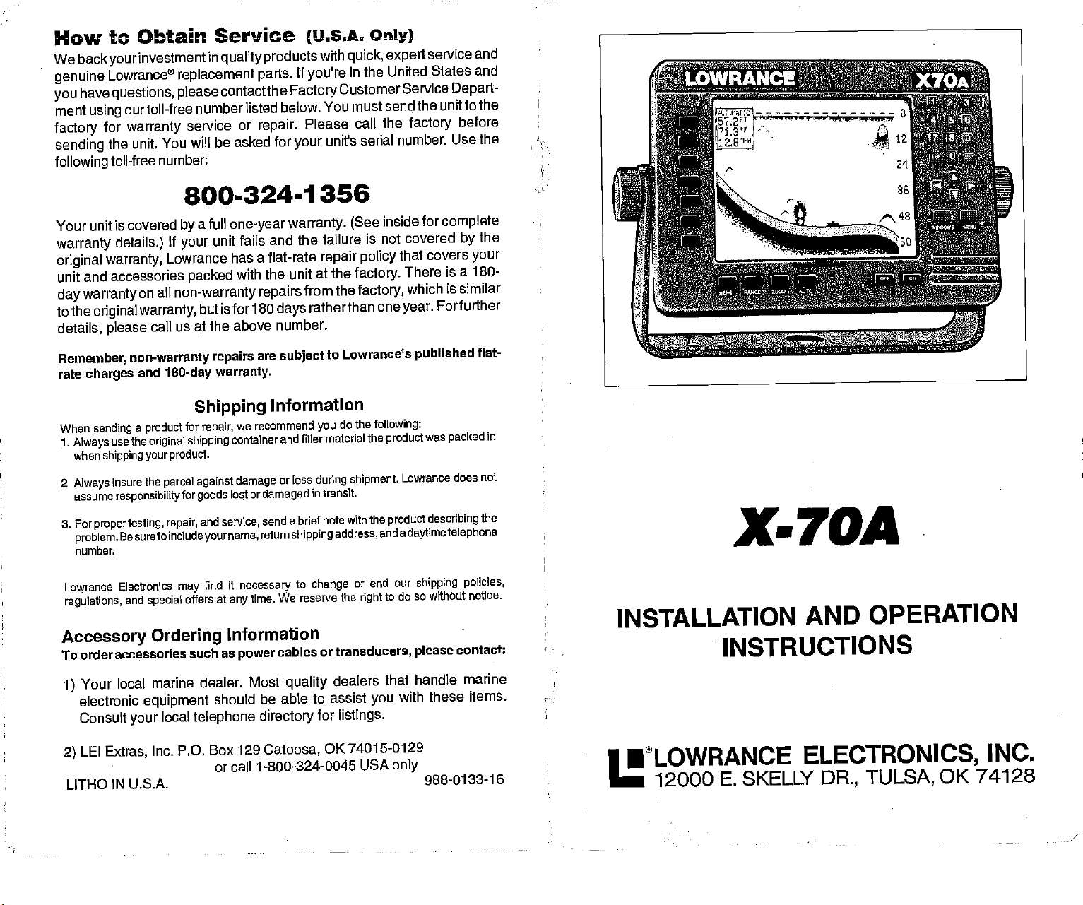
INSTALLATION
- INSTRUCTIONS
•LOWRANCE
I
—
12000 E. SKELLY
AND
ELECTRONICS,
DR.,
OPERATION
TULSA,
INC.
OK 74128
PDF compression, OCR, web-optimization with CVISION's PdfCompressor
/
Page 2
NOTES:
TRANSOM
Hand-held Drill with
MOUNT
Four stainless steel
Marine
grade
caulking compound
SHOOT-THRU-Ij(JLL
100
grit
One
Power
True
sold
Devcon®
The
Fahrenheit
temperatures higher
display
Formore
or
sandpaper
of
package
Poxy®,
Value® brand TRUE
True
by
the either
1 oz
Value®
brand PLASTIC
storage temperature
(-20
degrees
your
in
local
unit.
your
information,
service center.
package.
or lower than
This
TOOLS YOU
TRANSDUCER
a
variety
screws
(to
MOUNT:
of the
Made
BOND
WILL
INSTALLATION:
of small bits
attach X-70As
seal
(to
following
Power
by:
or
epoxy
stores or
WELDERTM
for
your
to +75
of
type
epoxy.
NOTICE!
unit is from -4
degrees Celcius).
specified
damage
contactthefactory's
NEED:
bracket to the
transducer
epoxies:
mounting screws)
Pox? Adhesives,
PLASTIC
will
is
not covered
CustomerService
WELDERTM
degrees
Extended
damage
to +167
the
the
by
dash.)
Inc. or
epoxy
degrees
storage
liquid
crystal
warranty.
Department
in
PDF compression, OCR, web-optimization with CVISION's PdfCompressor
Page 3
How to Obtain
We back
Lowrance
Factory
be able to solve the
may
You will be asked
Canada
investment
your
replacement parts.
Customer
Service
for
Only. Monday through
How
(International
If
need service or
you
WARRANTY REPAIR
Please follow the
unittothe
describing
telephone
daytime
When
sending
1.
Always
in when
2
Always
assume
3. For
proper
problem.
telephone
order accessories
To
1. Your local marine
equipment
directory
2. Canadian customers
Lowrance/Eagle
shipping
dealer.
Forpropertesting,
the
problem.
number.
a
product
use the
original
shipping your product.
insure the
responsiblity
testing, repair,
Be sure
number.
Accessory
should be able to assist
for
listings.
Service
(Canadian
in
Department
problem
unit's serial number.
your
Customers
quality products
If
you
and save
800-347-1014
with
need service or
the toll-free number
at
the inconvenience
you
8:00 AM.
Friday
quick, expert
to Obtain Service
Customers
contact the dealer in the
repairs,
WILL BE HONORED ONLY
UNIT WAS PURCHASED.
instructions
shown below on this
repair,
Be sure to include
Shipping
for
repair, please
goods
and
service,
container
lost or
name,
your
shipping
parcel against damage
for
to include
Ordering
such as
dealer. Most
Canada,
power
quality
you
can write:
only
919 Matheson Blvd.,
or f ax 41 6-629-3118
and
your
Information
do the
or loss
damaged
send a brief note
cables or transducers,
with these items.
country you purchased
send
service,
name,
following:
and filler material
during shipment.
in transit.
return
shipping
Information
dealers that handle
F.
Mississauga,
Only)
service and
contact
repairs,
listed below. A technician
of
returning
-8:00 P.M. Central Time.
genuine
the Lowrance
your
Only)
your
IN THE COUNTRY
have to mail
if
you
page
a brief notewiththe
retum
shipping
the
product
Lowrance does not
With the
product
address,
please
Consult
your
Ontario
marine electronic
address,
was
describing
a
and
contact:
local
telephone
L4W2R7
product
unit.
unit.
your
and a
packed
the
daytime
INTRODUCTION
MOUNTING
CONNECTIONS
POWER
TRANSDUCER
KEYBOARD BASICS
DISPLAY
MENUS
HELP
WINDOWS
VIEWING
MODIFYING GROUPS
RESETTING
SONAR OPERATION
AUTOMATIC
SENSITIVITY
RANGE
ZOOM-Automatic
ZOOM-Manual
MENU
CHART SPEED
GRAYLINE®
FISH 1.0
FISHTRACKTM
DISPLAY
MENU-PAGE2
ADJUST
BACK LIGHT ON/OFF
SPEAKERVOLUME
TURN DIGITAL BOX
CONSTRUCT
MENU-PAGES
MENU-PAGE4
MENU-PAGE5
SYSTEM INFORMATION
TRANSDUCERS
FISH ARCHES
SONAR TROUBLESHOOTING
WINDOWS SUMMARY
WARRANTY
MISSING
INTERNATIONAL
WINDOWS OPTIONS
ALL GROUPS
Operation
operation
-
PAGE
CONTRAST
BACK LIGHT LEVEL
OFF
BOX
DIGITAL
DISPLAY ZOOM
DISPLAY
DIGITAL SONAR
DEPTh
CHART CURSOR
FASTRAK
SELECT UNITS OF MEASURE
CLEAR
ADJUST
ADVANCED
BAR
ZONE BAR
UNES
DISTANCE LOG
CHART SURFACE
SIGNAL PROCESSING
AND CONE ANGLES
PARTS
SERVICE INFORMATION
Copyrighte
All features and
All screens in this manual
TABLE
CLARITY
OF CONTENTS
(ASP)
1994 Lowrance
All
rights
reserved.
specifications subject
Electronics
to
Change
without
are simulated.
I
1
3
4
12
13
IS
is
15
15
16
17
17
18
19
20
21
25
25
25
26
27
27
28
28
28
28
29
29
30
30
30
SI
SI
32
32
33
33
34
34
34
35
36
37
38
41
43
46
47
notice.
47
PDF compression, OCR, web-optimization with CVISION's PdfCompressor
Page 4
INTRODUCTION
The X-70A is a
high quality,
second to none in its class.
the X-70A is also one of the
built. The wide "ClearVision"
resolution and detail. The
operation.
temperature,
ST-T
The X-70A
and
distance travelled
speed/temperature
display
also has
sensor).
wide screen sonar
menu features
Using
easiest-to-use sonars that
screen shows the
and
keyboard
digital depth,
(log)
with
and
underwaterworld with
are also
boat
speed,
displays (requires
performance
that is
"soft-key' operation,
Lowrance has ever
high
lighted
for
night
surface water
an
optional
Please check the
items shown on this
special
A
it
toll-free number
RECORDED MESSAGE will
before
ready
items in the box
page.
call.
you
NOTICE!
this
against
If
are
you
missing any
1-800-324-1353
request
list. You should have all of the
of the
the
following
please
call our
items,
information. Please have
Read this manual and
It makes a
great
reference if
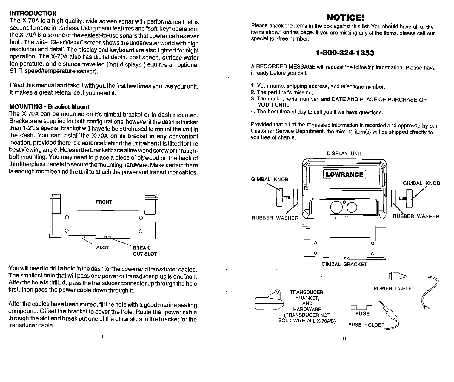
MOUNTING - Bracket
The X-70A can be
Brackets are
than
1/2",
a
special
the dash. You can
location, provided
bestviewing angle.
bolt
mounting.
thin
fiberglass panels
is
enough
room
mounted on it's
supplied
bracket
install• the X-70A on its
there is
Holes in the bracketbase
You
may
to securethe
behind the unitto attach
take it with
you
Mount
forboth
cOnfigurations,
will have to be
clearance
need to
the first few times
you
need it.
gimbal
behind the unit when it is tilted forthe
bracket or
however if the dash is thicker
purchased
bracket in
allowwood
place a piece
mounting
the
SLOT BREAK
of
plywood
hardware. Make certain
powerand
OUT SLOT
use
you
in-dash mounted.
to
mount the unit in
screworthrough-
convenient
any
your
on the back of
transducercables.
unit.
there
I.
Your
name,
2. The
part
3. The
model,
YOUR UNIt
4. The best time of
Provided that all of the
Customer Service
free of
you
GIMBAL
RUBBER WASHER
shipping address,
that's
missing.
serial
day
Department,
charge.
KNOB
number,
and
telephone
and DATE AND
to
call
requested
r
\
if we have
you
information is recorded and
the
missing item(s)
DISPLAY UNIT
OWRANCE]
[0°c
'-I
number.
PLACE OF
questions.
will be
tI
PURCHASE OF
approved by
shipped
directly
GIMBAL KNOB
RUBBER
WASHER
our
to
You will need to drill a hole
The smallest hole that will
Afterthe hole is
then
first,
After the cables
compound:
through
the slot and break out one of
pass
drilled,
the
pass
power
have been
Offset the bracket to
transducer cable.
in the dash forthe
one
pass
power
powerand
ortransducer
the transducerconnector
cable down
routed,
fill the hole with a
through
it.
cover the hole. Route the
the other slots in the
transducercables.
is
plug
up through
good
one inch.
marine
power
the hole
sealing
cable
bracket for the
11/3
(TRANSDUCER
SOLD WITH
TRANSDUCER,
BRACKET,
AND
HARDWARE
GIMBAL BRACKET
NOT
ALL
X-70A'S)
46
FUSE
FUSE
POWER
CABLE
HOLD)
PDF compression, OCR, web-optimization with CVISION's PdfCompressor
Page 5
Notes:
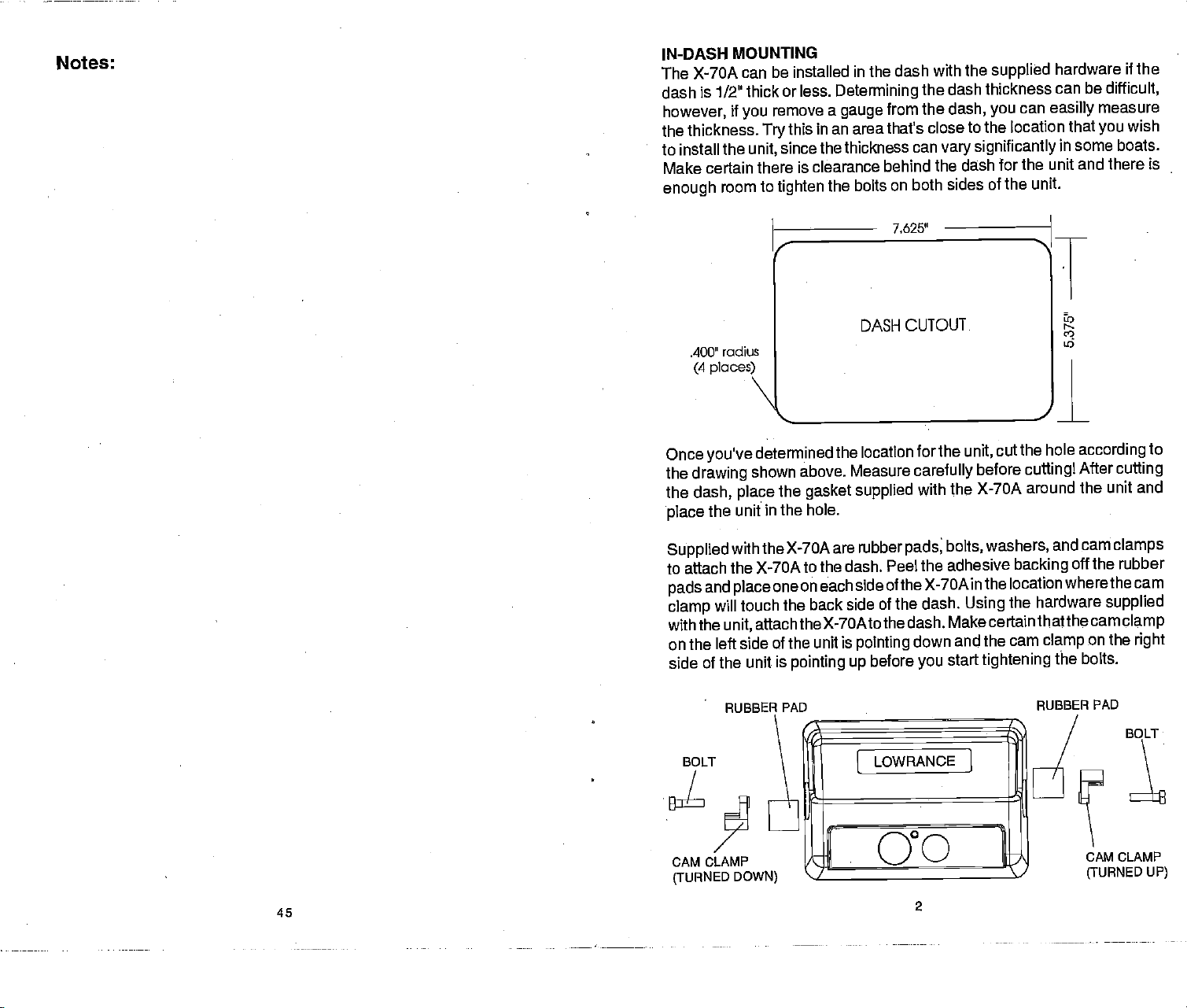
INDASH MOUNTING
The X-70A can
dash is 1/2' thick or
however,
thickness.
the
to install
Make certain
enough
the
room to
radius
.400"
(4 places)
be installed in the dash
less.
if
remove
you
this
Try
since the thickness
unit,
there is
tighten
with the
dash thickness can
Determining
a
gauge
in an area that's close to
clearance behind the dash
the bolts
DASH CUTOUT
the
from the
dash,
the location that
can
significantly
vary
on both sides of
7,o25"
supplied
can
you
hardware
easilly
in some boats.
be
difficult,
measure
you
if the
wish
for the unit and there is
the unit.
U)
45
Once
you've
the
drawing
the
dash,
the unit in
place
Supplied
to attach
and
pads
will touch the
clamp
the
with
left side of the
on the
of the unit is
side
CAM CLAMP
(TURNED
determined the location
shown above. Measure
the
place
gasket supplied
the hole.
with the X-70A
the X-70A to
one on each
place
attachthe X-7OAtothe
unit,
RUBBER
PAD
DOWN)
are rubber
the dash. Peel the adhesive
back side of the dash.
unit is
pointing
for the
carefully
with the X-70A around
bolts,
pads
side of the X-70A
dash. Make
before
down
you
2
start
pointing
up
unit,
before
cuttingl
according
After
the hole
cut
the unit and
washers,
and cam
backing
off the rubber
in the location wherethe
the hardware
Using
certainthatthe
and the cam
tightening
RUBBER PAD
on the
clamp
the bolts.
CAM cLAMP
(TURNED
camclamp
to
cuffing
clamps
cam
supplied
right
BOLT
UP)
PDF compression, OCR, web-optimization with CVISION's PdfCompressor
Page 6
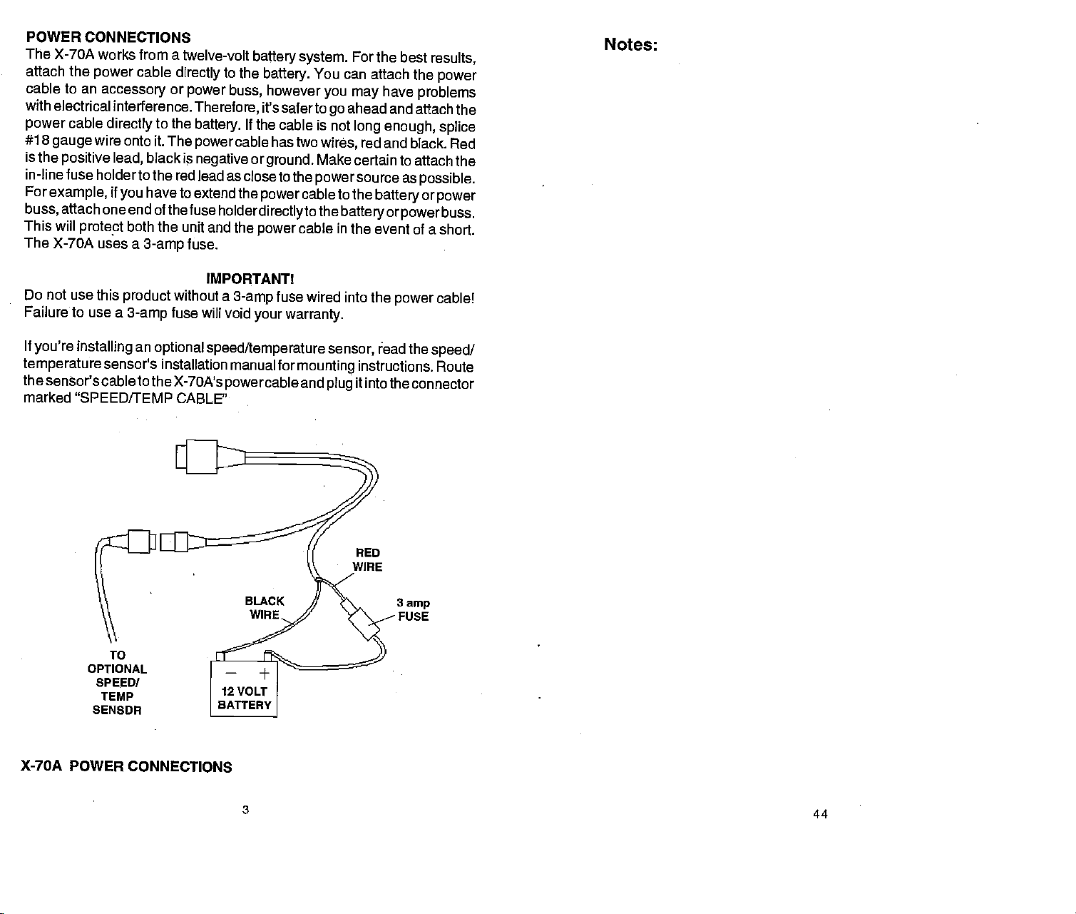
POWER CONNECTIONS
The X-70A
attach
cable to an
with
electrical interference.
power
#18
gauge
is the
in-line fuse holderto the
For
example,
buss,
This will
The X-70A uses a
Do not use this
Failure to use a
works from a
the
power
cable
accessory
cable
directly
to the
wire onto it. The
if
you
black is
have
positive lead,
attach one end of
protect
both the
3-amp
product
3-amp
directly
or
red lead as close to the
thefuse
without a
fuse will void
twelve-volt
power buss,
Therefore,
battery.
powercable
negative
to extend the
battery system.
to
the
If the cable is not
or
powercableto
holderdirectlytothe
unit and the
fuse.
IMPORTANT!
power
3-amp
your
battery.
however
You
it's saferto
has two
ground.
wires,
Make certain to attach the
powersource
cable in
fuse
wired into the
warranty.
For
the best
can attach the
you
go
have
may
problems
ahead and attach the
long enough, splice
red and black. Red
as
possible.
the
batteryorpower
batteryorpowerbuss.
the event of a short.
power
Notes:
results,
power
cable!
If
you're installing
temperature
the sensor'scable
an
optional speed/temperature sensor,
sensor's installation manual for
to the X-70A's
marked "SPEED/TEMP
TO
OPTIONAL
SPEED!
TEMP
SENSOR
CABLE'
powercable
mounting
and
plug
ead the
instructions. Route
speed/
it intothe connector
S
amp
FUSE
X-70A POWER
CONNECTIONS
3
44
PDF compression, OCR, web-optimization with CVISION's PdfCompressor
Page 7
LOWRANCE
FULL ONE-YEAR
"e",
product.
item for
We warrantthis
againstfailuretoconforn1tothisproduct'sWritten5Pecification5,af0roneYeil)fromt
date of
REPRESENTATION
Your remedies
manner
with the
"You" or
"your'
personal, family,
product
original purchase
under this
that
defect or malfunction
any
product's
purchase,
original
such
defect, malfunction,
purchase
identicalorreasOnablyequiValenttOthi5Pr0duct,at0ur0Pti0n,withirea50naetimeer
our
receipt
reasonable number
replacement
REFUND
AGAINST US FOR
INC THE
CAUSE WHATSOEVER.
TO ANYONE
RECT
PRODUCT OR FOR ANY
DAMAGE OF ANY
so the above
This
warranty
serviced or
been
connected,
according
been effaced, altered,
resulted
provide
owner's
We reserve
without
items
This
vary
from
reasonable
manual for the
incurring
previously
warranty gives you specific legal
from state to state.
REMINDER:
purchase
written
which must be
will either be
date
of the
product.
of the
productor
JUST
(AS
ANY
FOR ANY
limitations or exclusions
does NOT
repaired by anyone
installed, combined, altered, adjusted,
to the instructions furnished
accident, misuse, negligence,
any
the
right
the
manufactured:
You must retain
in case
warranty
or "us" refers to
"ou(,
LOWRANCE
refers to the first
or household
defects or malfunctions
against
by you.
OF ANY KIND WHATSOEVER
warranty
specifications,
substantiated
or
non-conformity
repaired
If such
of
attempts
DESCRIBED)
to
a refund
DEFECT,
WE WILL NOT UNDER
SPECIAL,
KIND.
in the
apply
or removed,
and
necessary
product.
to make
obligation
changes
to install such
the sales
service is ever
LOWRANCE
12000 E. SKELLY
ELECTRONICS
WARRANTY
ELECTRONICS,
who
person
use.
WE MAKE NO
available so
will be
in materials
occurred
without
defect,
repair by us, you may
forthe
IS THE EXCLUSIVE
MALFUNCTION,
LOSS OR DAMAGE RESULTING
CONSEQUENTIAL,
may
following
other than
with the
or
(4)
maintenance in accordance
or
rights
slip
or
a dated sales
by
occurs within one
which
charge
malfunction,
product.
not
apply
circumstances:
product,
when
any
or
improvements
improvements
and
you may
or sales
required.
ELECTRONICS
DRIVE
TULSA,
324-1358
(800)
43
INC.,
purchases
OTHER EXPRESS
long
workmanship,
within one
THIS
OR NON-CONFORMITY
ANY CIRCUMSTANCES
us, (2)
this
in materials and
CONCERNING
as
can show in a reasonable
you
year
or be
replaced
or
non-conformity
to obtain without
elect
REPAIR,
REMEDY
INCIDENTAL,
to
you. whenever the boat
(1)
when the
or handled in a
when
(3)
defect,
problem,
carelessness,
receipt proving
with the instructions
in our
products
or
changes
also have
OK 74128
the manufacturer
receipt
as a consumer
product
workmanship,
WARRANTY OR
THIS PRODUCT.
or
non-conformity
any
from the date of
sales
or
from
year
with
REPLACEMENT,
AVAILABLE TO YOU
FROM
OR OTHER INDI-
when the
product
manner other than
serial number
any
loss,
or from
other
the date of
slip. Any
your original
a new
product
remains after a
charge
CONCERN-
ANY OTHER
BE LIABLE
product
has been
or
damage
failure to
any
from time to time
on
equipment
which
rights
your original
of this
and
your
OR
has
has
has
of the
may
a
or
TRANSDUCER
Some X-70A's
be installed
boat. It can
through"
The
"kick-up"
strikes an
the bracket
up",
If
unit came with
your
attempting
for
right
the
hull,
cannot
critical
part
perform
Location
1. The transducer
water at all
then the chosen
transducer
show on the
The transducer should
2.
down,
3. If the
interfere
closer
will
transducer
increases
-
.
reduces the
4. If
possible,
boat.
can be
the
are sold with a HS-WS
on
any
outboard
also be
mounting
object
on some
while
can
easily
the hull
the installation.
boat. Use
your
since once it is
or stern-drive
permanently
fiberglass
bracket
the boat is
be
pushed
a
transducer,
Determine
extreme care if
epoxied
be removed. Remember,
of a sonar installation.
it's
at
designed potential.
-
General
must be
times. If the transducer
is not
sonar's
if
possible.
transducer is mounted
with the
than
approximately
prevent
cavitation interference
should be mounted
the chance that it
possiblity
route the transducer
Electrical noise
displayed
transducer cable around
placed
location
placed
display
is
moving.
trailer
of
from
on the
must be in the water
in a smooth
be installed
or
one
air bubble interference.
sonar's screen.
transom mount
(inboard\outboard)
installed inside the
boats.
helps prevent damage
moving.
If the transducer
back in
place
read this section
which of the
mounting
into
position,
the transducer
If it isn't done
in a location that
is to be mounted
flow of
in the
on the
hauling
foot from the
will be in the water
engine wiring, bilge
these wires.
form of random
with it's face
transom,
of the
with the
as
deep
cable
away
4
boat.
in the
transducer. It can
powered
boat to "shoot-
transducer
if the
does "kick-
without
tools.
carefully
mounting positions
the transducer
the transducer
location is the most
properly,
the sonar
usually
has a smooth flow of
inside the
at all times. If the
water,
engine's
propeller.
from other
Use caution when
interference will
lines or dots
pointing
make certain it doesn't
Also,
straight
don't mount it
lower unit. This
Typically,
water as
in
high speed
pumps,
possible.
wiring
and areators
before
is
inside
can't
hull,
the
This
and
the
on
routing
PDF compression, OCR, web-optimization with CVISION's PdfCompressor
Page 8
Shoot-thru-hull v.5. Transom
Typically1
tion and
damage
loading
However,
some loss of
from hull to
is
caused
of
the transducer cannot be
be a
slow
installation section in this
shoot
TRANSOM MOUNT
1.
First attach the
Next,
pad keeps
low
shoot-thru-hull installations
to excellent
good
from
floating objects.
on the
trailer.
the shoot-thru-hull
sensitivity
even from
hull,
differences in hull
by
problem
trolling speeds.
through
slide the rubber
speed.
on some hulls
the hull.
tension on
Don't close the
does
Follow the
manual to determine if
-
Assembly
mounting
into the
pad
the bracket's
depth
installation does have its
occur,
different installations on the
adjusted
that sit with the bow
bracket's halves
bracket at this timel.
Mounting
excellent
give
capability.
It can't be knocked off when
even on the best hulls.
and
layup
procedure
latch, preventing
construction.
for the best fish
listed in
together
between the
space
high speed
There is no
drawbacks.
same hull. This
Two,
arches. This can
when at rest or at
high
the shoot-thru-hull
can
you
as shown below.
two slots. This
it from
possibility
satisfactorily
opening
opera-
of
docking
This varies
the
or
One,
angle
at a
I
70.7
I—
.1
60
—
I
_______
liwnr..n
0
100
48.8
•
,—'
GROUP "0"
I 8.6k 15.01
19.3
r
'
GROUP "F"
__________
ijiir .....
,,
GROUP
rrrn
-
°.
.—r-
"E"
--
S—.
:-BD
—n,k!—..—th.— —,.———.—....,————
50.6
SUALLOU
BE!?
ALABH 0 ALARM
OFT
GROUP "G"
14.4
6 ib
-
so
RUBBER PAD
•'EiIwsu'rnau1
70.7
C
:
H
RflIfl1NISt]
isn.
100
5
•pIvpets.
0
'
GROUP "H"
14.4
42
— —
6.9
12.6
•,rnfl,ul lii
0
GROUP "I"
I-,'
Ic
.Ix
I',
PDF compression, OCR, web-optimization with CVISION's PdfCompressor
Page 9

the
display,
problem
or tachometer
routing
routing
problems.
wiring
the sonar
the
power
Make certain
the
power
could be one of
wiring. Try using
unit's
power
cable
directly
to use the in-line fuse
to the
cable
battery.
three
resistor
cable
away
to the
things; spark plugs,
spark plugs,
from
battery
supplied
alternatorfilters,
engine wiring. Again,
eliminate noise
helps
with the unit when
alternator,
or
2.
Slip
"ears".
one side of
the other side
TWO
transducer's
the
Sandwich two internal lock
the
mounting
mounting
bracket as shown
of the transducer.
ONE WASHER
between the bracket's
pad
washers between the transducer and
below. Place one washer on
mounting
When no noise
the noise source is
limited
experience
in shallow
malfunction will be the location
of the
of the transducer must
face
water at all boat
of
best
mounting position.
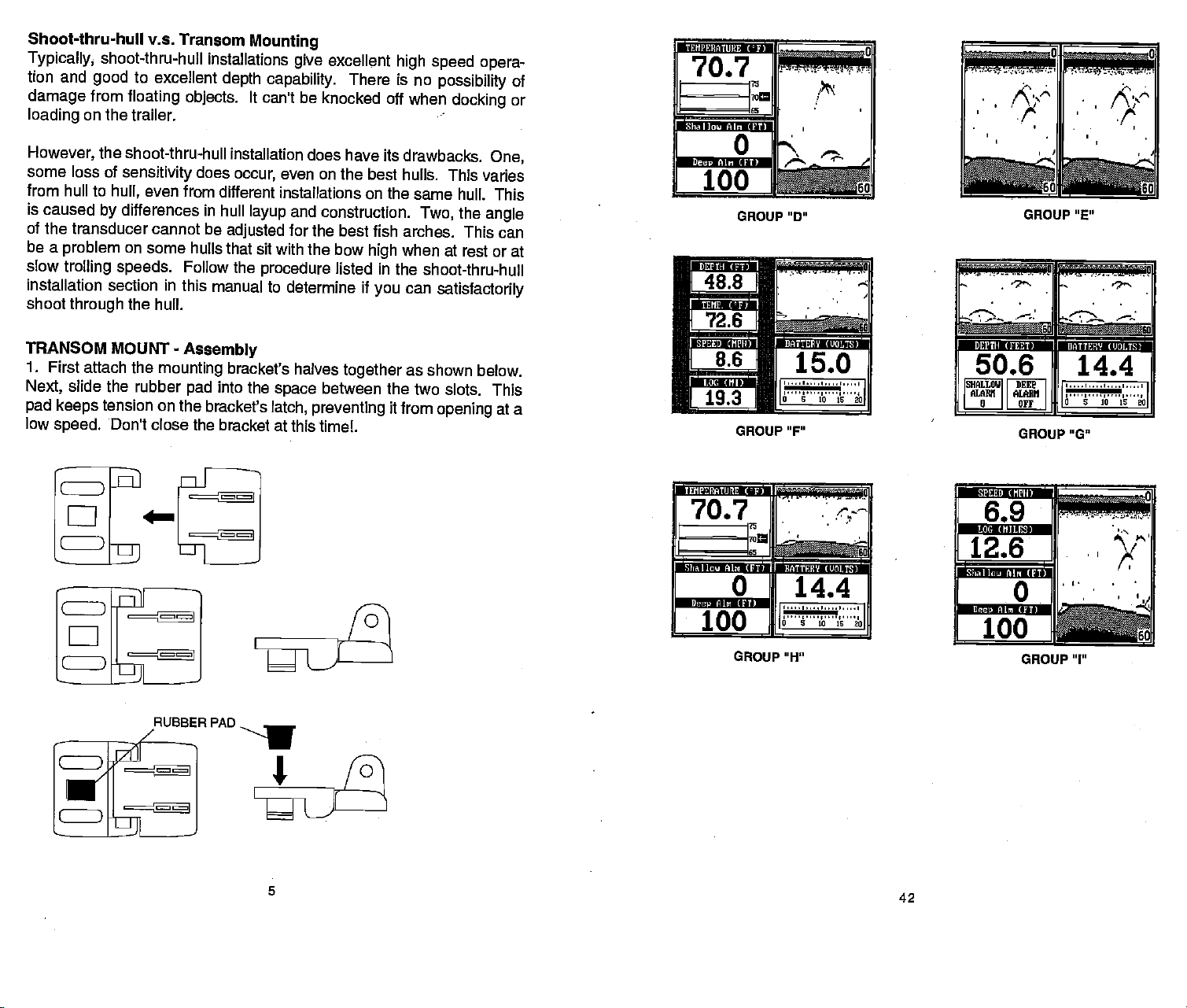
WINDOWS SUMMARY
All of the window
70A are shown
To view these
WINDOWS
the down arrow
unit
through
each
group
ever the
DEPTH (FEET)
F
on these
shown
turned off.
49.2
SHALLOW DEEP
ALARM
a OFF
appears
probably
make
or when the boat
water,
speeds.
groups
on the
following pages.
groups,
key,
all
can be customized,
group
lETEMPERATURE
simply press
then
Thiswill
key.
groups.
will revert
pages
70.7
ALARM
—
6.9
rnletu,,,fl,1
12.6
:
-
!
GROUP "B"
on the sonar unit after all of the
cavitation.
sonarinstallationswhich
hasty
used
repeated press
is at rest. In
and/or
be
placed
Read
by
"cycle"
Remember,
in a location that
transducer owner's manual
your
the X-
the
the
how-
Many
nearly
angle
novices
all
the transducer. The
of
to the ones
when the unit is
cFfl
,
.
41
above
or
persons
function
cases,
has a smooth flow
GROUP
'A"
GROUP "C"
then
tests,
with
perfectly
the cause
forthe
BOLT &
4llll1lllllluh1llllllffluI
BOLT
3. Slide
the
lock washer over the end
tighten
INSTALLATION - Transom
1. The
water at all
against
random marks
carefully
determine the best
2. Make certain
trailer.
unit. This
propeller.
the metal sleeve
bracket, washers,
the nut at this time.
transducer must be
times. Air bubbles created
the water
interfere with the sonar
to
the water's
view
the chosen location doesn't
Mount the transducer at least
will
prevent
over the bolt.
and transducer
of the bolt and thread
appear
path
location for the transducer.
air bubbles from the
liii
Slip
assembly.
The
transducer
Mount
a location that has a smooth flow
placed
on the sonar's
in
by
at the transom
one foot from the
6
SLEEVE
bolt and sleeve
the
an internal tooth
Place
the nut onto it. Do not
now
is
ready
through
for installation.
S
the movement of the boat hull
signal.
transducer
This causes "noise"
display.
while the boat is
You
interfere with the
may
moving
engine's
interfering
or
need to
to
boat's
lower
with the
PDF compression, OCR, web-optimization with CVISION's PdfCompressor
Page 10

CLAMP ThE
TRANSOM NEARThE
WILL HELP PREVEIITTHE TRANSDUCER
FROM ENTERING THE BOAT IF ri IS
KNOCKED OFF AT HIGH SPEED.
CAUTION!
TRANSDUCER CABLE TO
TRANSDUCER. This
GOOD LOCATION
2.Thesensitivitymaynotbehighenough. inorderfortheunittodisplay
a fish
enters the cone until
unit
displays
3.
Use the Zoom feature. It is
zoomed in on a small
will have much better
than a 0 to 60 foot
to show much more
it has to be able
arch,
the fish
it leaves. If the
when it is in the center of the cone.
only
of water than a
range
luck
seeing
This
range.
detail.
to receive, the fish's echo from
sensitivity
much easier to
fish arches with a 30 to
enlarges
the
is not
high
enough,
fish
display
large
one. For
arches when
example, you
60 foot
targets, allowing
the time it
the
range
the
display
3. Don't mount the transducer
bottom of the hull.
between the ribs closest to
of the transom is
not
possible,
4. Once
bracket
to the
ground.
the centerline of the
below.) Swing
the starboard
you
against
Typically,
preferred
determine the
the
transom. The transducer should be
The bottom of the
transducer and it's bottom.
the
bracket
a
the
engine. (See above.)
for
mounting
(right)
best location for the
and mark the transom
up
the transducer bracket. Now drill
Use the #10 stainless steel
ducer to
loosely
attach the
sheet metal screws
bracket to the transom.
TRANSOM
LOCATION
directly
good
side can be used with
hull should be about
behind strakes or ribs
location on aluminum
The
port
the
transducer,
however if
good
transducer,
roughly parallel
halfway
the
(See
through
the slots in
two holes in the center of the
supplied
with the
on the
boats is
side
(left)
this is
results.
hold
the
between
illutration
slots.
trans-
4. The
NOISE
A
on
it can
operate
To
boat must be
the boat is
straight
major
motionless,
horizontal lines.
cause of sonar
the sonar's
completely
erraticly,
eliminate or minimizethe effects of
moving
display
cover
or not at all.
at a
fish
stay
problems
as
random
the screen with black
the cause. With the boat at rest in
is turn all electrical
also. Turn
off,
Processing).
turn on each
on the
sonar's
sonar
display
on the
VHF radio and transmit.
has been turned
If
find noise interference from
you
or
pump,
radio,
sonar unit's
is
causing
the interference. VHF
transmitting,
need to
it from
route the sonar unit's
other
equipment
your
There should be a
of electrical
piece
display.
for noise. If no
theireffect
on,
to isolate
try
cable and transducer cable
power
so be certain to
on the boat.
wiring
X-70A
For
on the boat off. Make certain the
on,
steady
equipment
example,
noise is
Keep doing
on the
the
keep
power
slow
trolling speed
in the
cone,
is
electrical noise. This
patterns
the
then
of dots orlines. In severe
electrical
the first
water,
turn off ASP
bottom
to see fish arches. If
showing
dots,
noise,
signal
on the
usually appears
or cause
firsttryto
thing you
(Advanced
on the
display.
display
the unit
determine
should do
engine
on the boat and view the
turn
on the
bilge pump
present,
turn the
this until all electrical
sonardisplay noted,
an electrical
problem.
instrument,
You can
usually
away
radio antenna cables radiate noise
the sonar's wires
cable
directly
awayfrom
to the
and view the
pump off,
then
trolling
re-route the
from the
battery
then
equipment
turned off.
wiring
it. You
to
as
cases,
is
Signal
Now
effect
turn
motor,
that
when
may
isolate
OF BOAT
If no noise
certain
displays
everything exceptthe
Increase the RPM
7
on the sonar unitfrom electrical
with the
sonar unit
gearshift
is turned
in
neutral. If noise
40
off,
equipment,
then startthe
appears
then
engine.
make
on the
PDF compression, OCR, web-optimization with CVISION's PdfCompressor
Page 11

bottom
Weak
1. Make
transducer.
reducing
be sure it is
securely
echo, digital
certain transducer is
Oil, dirt,
its effectiveness. If the transducer
shooting through only
bonded
to the hull. Do NOT
or MarinetexlM.
Electrical noise
2.
causes the sonar
rejection
as fish or
such
3. The
water
sonar can't find the
the
the
digital
greater
manual
100
than
mode,
feet)
a bottom
4. Check the
also
power
Bottom echo
weak bottom
1. The transducer
smooth flow of water
bubbles in the
from
to
feature. This
even structure from the
be
may
will flash
the water
then
increasethe
and
should
signal
battery voltage.
drops, reducing
disappears
echo while boat is
may
water
to find the bottom
Cavitation.
2. Electrical noise from
causes
rejection
such
plugs
other
the sonar
feature. This
as fish or even structure
or
routing
electrical
the
wiring
readings
pointing
and fuel can cause
straight
one
boat's motor can
the
automatically
increase
can cause the unit
deeper
than the sonar's
bottom
continuously.
you
signal
are in. If this
It
changethe range
sensitivity.
appear.
If the
voltage drops,
its
ability
at
high
speeds
moving:
be in turbulent
in orderforthe
disrupt
or other
the sonar
targets.
the boat's motor
to
automatically
can cause the unit to
from the
sonar unit's
on the boat.
power
fish
erratic,
or no
down. Clean
a film to form
signals:
the face of the
on the
transducer,
is mounted inside
of
layer
use IRTV silicone rubber
fiberglass
interfere with the
and
sonar. This
its Discrimination or
to eliminate weaker
display.
to find the bottom.
ability
while it's
may change
to a realistic
As
you
to find the bottom
water. It must be mounted
sonarto work at all boat
signals,
The
can interfere with the
increase
display. Try
and transducercables
in the automatic
the
range
happens, place
one, (for example,
into
move
or erratic
interfering
technical
its Discrimination
eliminate weaker
shallowerwater,
unit's transmitter
the
digital
term for this is
using
to limits
the unit in the
or
targets.
reading
speeds.
with its
sonar. This
resistor
the
hull,
that it is
adhesive
noise
signals
If
mode,
far
0-
or
in a
Air
ability
or noise
signals
spark
awayfrom
5.
Adjust
is
slightly
manual for
Don't
Overtightening
the transducer
the transducer
lower than the back.
proper
overtighten
transducer
the bolt that
the bolt
to
"kick-up"
together by pressing
attached) against
Clamp
This
off at
the
will
prevent
high speed.
FLAT-BOTTOM HULL
NOTE: Some
hull create
typically
speeds
have
over 35
the hull as
of the transducer
at
work
high
the one screwed to the
transducer cable to the
the transducer
aluminum boats with strakes
amounts of turbulence
large
possible
speeds.
outboard motors
large
mph.
pn
below the turbulent
6. Route the transducer
cable
from
engine wiring
on the transducer cable.
up
unwanted
from other
away
or
interference on the sonar
and bracket so that the
See the section on
angles. Tighten
holds the transducer
in a distorted bracket
result
may
at
the outer bracket
speed.) Snap
high
(the
transom.
IMPORTANTl
transom close
from
entering
at
capable
The transducer should
these boats.
cable to the sonar unit.
on the
wiring
bilge pumps
This can show
below)
(See
water, allowing
boat,
can be
picked
display.
front of the transducer
fish arches in this
screws.
all
(CAUTION;
to the bracket.
which will allow
transducer bracket
the
one with the
transducer
to the transducer.
the boat
DEEP-"vEE" HULL
if it is knocked
or ribs on the outside
high speed.
of
propelling
be mounted
This will
These boats
the
as far below
the face
place
the sonar
the transducer
Keep
if
possible.
as
up
Electrical noise
of the
boat at
unit to
No fish arches when
1. Make
certain transducer
common
in
your
problem
owner's manual
the Fish ID feature is off:
is
pointing straight
if a
arch is
partial
displayed.
for more information.
39
down. This is the
most
Seethe Fish Arch section
Make a test run to determine
7.
is interference on the
there
the boat at
high speed, try
display
transducer's bracket as shown
the results. If
when
running
lowering
at
right.
the
PDF compression, OCR, web-optimization with CVISION's PdfCompressor
Page 12

SHOOT-THRU-HULL
The
transducer installation
that does
layers.
ful
transducer installation
(such
not have air
The sonar
as
plywood,
the material is removed
manufacturers use a
finishing
fiberglass
with an outer
and the balsa
INSTALLATION
bubbles in the resin
must
signal
can be made on hulls
balsa
wood,
from the chosen
layer
layer
wood core
The transducer can then be
After the
glass.
Remember,
bubbles in the
signals.
To choose the
60 feet of water.
transducer into the sonar
epoxy cures,
the
sonar
signal
fiberglass
proper
or the
location for thru-hull
Add a little water to
unit,
inside a
pass
through
or
foam)
of
fiberglass,
of
fiberglass.
exposes
epoxied
the hull is
must
pass through
epoxy
turn it
hull
fiberglass
solid
must be in an
or
separated fiberglass
fiberglass.
with flotation
between
then a core of balsa
Removing
layers
area. For
the outer
directly
watertight
to the outer
and
solid
will reduce
mounting,
the
then hold the
on,
or eliminate the
of the boat.
sump
area
A success-
materials
of
fiberglass
example,
the inner
of
layer
layer
structurally
fiberglass. Any
anchor the
transducer over
some
wood,
layer
fiberglass.
of
fiber-
sound.
sonar
boat in
Plug
of
air
the
the
etc.,
arches.
One of the
of the
if
the
sensitivity
best
water. For
segment,
expandsthe echoes,
the
sensitivity up
screen.
arches.
If
fish
see fish
you
symbols
In medium to
when the Fish I.D.
sometimes
to
ways
get
example, using
cannot be increased
fish
arches is to
the 2X or 4X zoom feature.
the better the screen
it easierto see detail. Forthe best
as
possible
deep water,
when the
unit is in the manual
feature is
this method should
as
high
signals
making
enough
expand
resolution will be. The
without
getting
or "zoom" a
too
much noise on the
work to
mode,
on,
try increasing
to
fish
get
segment
The smaller
zoom feature
results,
display
but don't
the
turn
fish
get
sensitivity.
TROUBLESHOOTING
If
unit is not
your
following
service
department.
working,
troubleshooting
or if
section before
It
save
may
need technical
you
contacting
the trouble of
you
help,
please
the
factory
returning your
customer
use the
unit.
FILL WITH EPOXY
0
INNER HULL
a
________________________________________
/
aCika
EPOXY TO HULL FIR5T—
the side of the boat.
second bottom echo is
automatic and ASP features
been set.
water in the
Next,
sump
a noticeable decrease in
disappear
and the
Adjust
seen on the
take the
of
transducer out of the water
the boat. Observe the
sensitivity.
bottom
signal may
transducer around to find the
to be increased
greatly
mounted on the outside of
shot
through
pages
for a shoot-thru-hull
the hull the best
to
compensate,
the hull. If
mounting.
the
sensitivity
display. (you
Don't touch
oft)
The second
decrease in
best location. If
then
not,
and follow the
N.
OUTER HULL
and
controls until a
range
will need to turn the
the controls once
and
sonar
the
to see if there is
signal
bottom
intensity.
sensitivity
they've
it in the
place
signal may
Move the
control has
thetransducer should be
then mark
instructions on the next
the location that
Unit won't turn on:
1. Check the
2. Make certain the
to the
positive battery terminal,
3. Check the fuse.
4.
Measure the
at least 11 volts. If it
terminals or
charging.
Unit
freezes,
1. Electrical noise from
be
may
interfering
transducer cables
Route the sonar
help.
of
through
2.
Inspect
3. Check
are
the
both the transducer and
securely plugged
cable's connection at the unit.
power
power
battery
on the
wiring
locks
up,
away
a fuse block or
transducer cable for
cable is wired
voltage
isn't,
at the unit's
the
wiring
terminals
or
operates erratically:
the boat's
properly.
black to
to the unit is
are
motor,
negative
power
corroded,
trolling motor,
with the sonar unit.
from
other electrical
unit's
ignition
in to the
cable
power
switch
breaks, cuts,
power
unit.
connectors. Make
Also check the
The
connector.
defective,
Re-routing
wiring
directly
to the
or
pinched
red wire connects
or
ground.
It should be
the
battery
or the
battery
or an
accessory
the
power
on
the boat
battery
instead
wires.
certain both
wiring.
needs
and
may
9
38
PDF compression, OCR, web-optimization with CVISION's PdfCompressor
Page 13

of the
edge
whether
signal
you
shows
are over
the true
you
rocks, mud,
depth.
etc.
The
rest of the
signal
tells
you
TRANSDUCER
(HIGH
LOCATION
TRANSDUCER
(TROLLING
LOCATION
SPEED)
if the cone
X-70A
resolution limitations
FISH ARCHES
Fish
distance
page.
as shown
shown in "C".
Very
partial
will
Because of
passes
may
arches are created
to a fish
When the center
"B". As the cone
small fish
arch,
but turn the
arch,
over a fish
not arch at all. This is due
when the cone first strikes
probably
ora
shape
water
conditions,
in shallow
water,
to the narrow cone
of the
display.
when the cone
of sound
it is shown as
of the cone strikes the fish,
leaves the
will not arch at
similarto an arch if
sensitivity up
such as
the distance increases
fish,
all. Medium sized fish
they're
in
deeper
heavysurf
the
signal
passes
the distance
in
deepwater.
water to
ace
clutter,
displayed
diameter and the
over a fish. The
"A" on the next
see the arch.
thermoclines,
on the
is shorter
as
again
will show a
Largefish
Shoot-thru-hull
Make certain
1.
both the inside surface
sand
with 100
transducer
grit sandpaper.
face is in contact
SAND THIS SURFACE
Installation
the area is clean, dry,
of the hull
The surface of
with the hull
SPREAD
and free of oil or grease,
and the face
the hull must be flat
to
prior
of the transducer
so the entire
bonding.
then
ss4
the
epoxy package
will cause bubbles
as it
specified
may
face of the transducer
onto
a minimum amount
with
epoxy
on
result in
the sanded
and
turning
The face of the transducer
dries,
19
page
I
A
p
37
B
p
C
2. Follow the
Do not
(NOTEl
to use one
Apply
then
transducer
out from under
be
hull and
mix it too
Use
only
of these
small amount on the
a
spread
parallel
a small
into the
with
transducer. After the
instructions on
fast,
the
epoxies
epoxies
amount
epoxy, twisting
the transducer face.
the
hull,
PDF compression, OCR, web-optimization with CVISION's PdfCompressor
and mix it
thoroughly.
to form in the
this manual!
1 of
sonar
poor
area on the hull. Place
itto
of
route the
performance!)
as shown
force
epoxy
cable to the X-70A.
air bubbles
any
between the
epoxy.
Failure
above,
the
should
Page 14

LOWRANCE
ED
ED
C
C
C
C
C
mm
ENS flANGE ZOOM AUTO
KEYBOARD
The
keyboard
horizontal rowatthe bottom.
of the
screen lets
the left column are used for
corner of the
right
the
bottom of the screen are used
the
range, zoom,
has
keys arranged
enter and
you
keyboard activates
and switch from
in
a vertical column on the
Aten-keypad
change
menu selections. The menu
to activate the
automatid to the manual
and arrow
data on the
the first menu
sensitivity
keys
screen. The
page.
X7OA
rnirn
1J
CC
"*lDOW5
i.1E'UJ
left
on
the
rightside
in the bottom
key
The
keys along
menu,
mode.
I
plus
keys
adjust
in
TRANSDUCER CONE
The
Sound waves from the
shaped
between the outside
Lowrance offers achoice of
angle.
Typically,
in
beam. This looks much
Thetransducersupplied
widecone
shallow to medium water
to see more of the
covers an area about
about a two foot circle.
The
20
the
-freshwater,
Since
degree
8
degree mostly
the sound
to much
Both 8
degree
even
though
is
because
a
transducer
1 OOfeet
energy
deeper depths.
and 20
the bottom
are
you
ANGLES
transducer
of
edges
angletransducers
underwaterworld. In 1 5feet of
sixfeet across. The 8
in salt
-
saltwater)
degree
seeing
the cohe is the cone
transducerswith eitheran 8
with the X-70A has a20
depths.
is almost
water. In a
is
concentrated in a smaller
transducers
is much wideron the 20
signal
more
spread
like the beam from
(20 degrees)
The 20
always
deep
the narrowcone
of the bottom.
out into
degree
degreetransducercovers
the
water
accurate
give
the water in a cone
a
flashlight.
angle.
or2O
degreecone angle.
are ideal
cone
waterthe2o
best to use in fresh
environment,
is more desirable.
angle
area,
degree
Remember,
degree
foroperating
allows
angle
degreecone
it can
bottom
model. This
the shallow
The
(300
penetrate
readings,
angle
cone
you
only
water,
feet
WINDOWS - This
you
MENU
SENS
RANGE - This
ZOOM
-
Pressthis
-
Press this
key
mode.
-
The X-70A
key gives you
customize
showthe
keyto
to
key
lets
you adjust
gives you
access to the windows
displays.
menus and
the unit's
adjust
the
range
2X and 4X
11
accessto
gain
sensitivity.
when the unit is
zoom
capability
which lets
mode,
mostfunctions.
in the manual
With
this
key.
20
degree
TRANSDUCER CONE ANGLES
36
8
degree
PDF compression, OCR, web-optimization with CVISION's PdfCompressor
Page 15

sources
engine
ing,
thefaceofthetransducer,
vibration from the
cases,
wanted marks on the
such as
ignition systems
air bubbles
noise can
bilge pumps,
and wir-
passing
engine.
produce
over
even
In all
un-
display.
The ASP feature has three lev-
-
els
you
using
However,
ble with
source and
setting.
However,
This allows
the ASP
To
the "More"
Medium,
Low,
have
high
the
if
noise,
there are times when
feature.
change
"I-ugh"
you
fix
you
the
label until thefifth menu
to the "Level of
and
High.
noise
levels,
try
ASP
setting.
are
we
rather than
it,
to view all
ASP
having
suggest
level,
trou-
that
continually using
incoming
press
ASP" label until the desired level is obtained.
SYSTEM INFORMATION
The
System
gives you
Information
the date and revision
menu
number of the software used in
the X-70A. To view this
the Menu
press
the
until the fifth menu
pears.
to the
next to the "More
key
Now
"System
key,
press
Information" la-
then
page ap-
the
key
menu,
press
label
next
bel. A screen similar to the one
atrightappears.To
sonarscreen, pressthe key
returntothe
next
to the "Exit" label.
If
you
you may
echoes
the MENU
page appears.
F
take
want to
to find the interference
steps
unit with the
the
turn the ASP feature off.
before
then
key,
SYSTEM JMFOEIIATJON 1
LOURANCE ELECTRONICS
COPYRJGHT 1993
CODE VERSION
they
press
Then
X—VOA
are
processed by
the
press
——
t13.6A
high
key
the
ASP
next to
key
next
AUTO - This turns the automatic feature
-
This
CLR
ENT - This
ARROW
ON - The ON
clears menus
key
is used to enter numbers
key
KEYS - These
move
turns the X-70A on.
key
OFF - Press and HOLD
and erases entries from the screen.
are used to make
keys
objects
the Off
on the screen.
to turn the X-70A off.
key
DISPLAY - General
The
firstturnedon. Menus
the
display
the
disappear
key
The Metric
key adjacent
This also
knots,
The
contrast for the
the
best
approximatelyten
1.OFT
are turned on for
lights
appearatthesametime.To
key adjacent
and
lights
the left side of the zero
on
to the
keyboard.
will
automatically
afterten
seconds,
label at the
the Metric label to
to
changes
and
log
Display
contrast,
the
to kilometers.
menu onthe
best
viewing
the
right
viewing angle, press
seconds
approximately
It controls the
label.
Light
If
don'twantthe
you
turn themselves
turn them off
can
oryou
(0) key.
of the screen works
top
change
temperature display
rightsideof
angle. Pressing
increases it. After
arrow
the CLR
and itwill
thescreen
key
automatically
12
24
48
60
off and on.
and make selections.
menu selections and to
ten seconds when the
keepthe lights
backlighting
wait ten seconds
on,
lights
off. The menus
by pressing
the same
the
depth
to
degrees Celsius, speed
Ietyou
the left
setting
to erase
Contrast
formation on this
When the X-70A
on,thedisplaywill
larto the one at
"AUTOMATIC" in the
corner of the
way.
from feet to meters.
adjustthe display's
arrow
key
the contrast for the
the menu or wait
erase. See
section for more in-
feature.
is first turned
left. The word
display
the automatic feature
The
displayed
digital
bottom
in this box.
X-70A is
on, press
on the
used
and
will also
CLR
the
Press the
to
decreases
the
Display
appearsimi-
upperleft
indicates
is on.
is also
depth
35
12
PDF compression, OCR, web-optimization with CVISION's PdfCompressor
Page 16

MENUS
I he X-70A uses menus
exten-
sivelyto guideyouthroughthe
functions and features of
unit. The menu
of these
many
ing you
to customize the
your particular
ter conditions.
have to leave
may
and
enteranotherto reach the
desired function,
to do is
return to the sonar
press
HELP
An
menus.
gives
example, pressing
press
the CLR
extremely
Virtually every
one or more
key
features,
needs
Although you
one menu
all
the
key
screen,
key.
useful feature
pages
the AUTO
unit into or out of the automatic mode A
screen.
Pressing
the
the
accesses
allow-
unit to
and wa-
have
you
next to the "More" label to select the
simply press
incorporated
feature has a
of text
describing
key brings up
key adjacentto
the
into the X-70A
help
the
help
key
menu
how
a menu
help
label
next to the "Exit" label or
label
to use that feature. For
label also
of how automatic works and how it affects different
-
series is the
when
that,
letting you
appears
gives
you
functions.
next menu. To
Help
pressed,
switch the
on the
a
description
MENU-PAGE5
ADJUST
CLARITY
The
ward
chart are called "surface clut..
ter." These
caused
wakes,
and other natural causes.
The Surface
(SCC)
surface clutter
display.
tivityof
it near the
increasing
creases. The maximum
that
selected
ample,
maximum
will be reduced down to 45 feet.
CHART SURFACE
markings extending
down-
from the zero. line on the
markings
wave
b'
temperature inversion,
action,
Clarity
are
boat
Control
reduces or eliminates
signals
from the
SCC varies the sensi-
the
receiver,
surface and
it as the
decreasing
gradually
in-
depth
depth
SCC will affect is 75% of the
depth range.
on a 0-60 foot
SCC,
For ex-
with
range
surface clutter
rty fl'g
-
rs3
SURFACE CLUTTER
/
vflt7tjjJa'r
0
12
24
36
48
60
WINDOWS
You can
This lets
change
you
This feature
the
displays
customize
gives you
displays
9
different window screens.
The screens available in the
on the X-70A
to
your
own
by using
fishing
the windows
or
boating
situations.
feature.
There are three levels of 8CC available on the X-70A:
When it's turned on forthe
high.
it,
pressthe
fifth menu
MENU
page appears.
key,
then
Now
pressthe
CHART SURFACE CLARITY"
firsttime,
press
label until the black box is on the desired
the SCC level is low. To
nextto the
key
the
key adjacent
"More" label until the
5CC level.
low, medium,
to the "ADJUST
and
change
windows mode are divided into
two or more windows
screen. Each screen of win-
dows is called a
"A" as shown at
digital displays
and the sonar chart in the other.
"group". Group
right
in one window
per
has the
Press the
ASP
(Advanced
The ASP
constantly
interference. This
next to the
key
"EXIT" label when
Signal Processing)
feature is a noise
evaluates the effects of boat
automatic feature
rejection system
gives you
finished.
you're
built into the X-70A
speed,
water
the best
conditions,
display possible
that
and
under most conditions.
13
The ASP feature is an
noise is
undesired
any
effective tool in
signal.
It is caused
34
combating
electrical and mechanical
by
noise. In sonar
terms,
PDF compression, OCR, web-optimization with CVISION's PdfCompressor
Page 17

SELECT UNITS
The X-70A
watertemperature
hour,
per
kilometers,
To
change
pressthe
the
until the fourth
pears.
centtothe "Select
sure" label.
below
on each line shows
measure
screen shown
MENU
next to the "More" label
key
Now
appears.
currently
of measure are in
depth, temperature
hour and
Press the
the
press
meters. This movesthe
have the units of measure
you
label.
"Exit'
CLEAR DISTANCE
The X-70A's
on. To reset the distance
zero, pressthe
the "CLEAR DISTANCE
label
appears,
key adjacent
X-70A returns to
screen with the
OF MEASURE
can
displaythe
in
degrees
kilometers
or nautical
the units of
press
The screen shown
per hour,
miles.
measure,
then
key,
menu
page ap-
the
key adja-
Units of Mea ________
The black box
the unit of
in use. In the
above,
the units
feet for the
in
is in statute
log
adjacent
key
key
next to
log
to that
starts
MENU
then
label. The
the sonar
set to zero.
log
the
LOG
press
water
Fahrenheit
press
in
depth
or
feet,
orCelsius, speed
and distance
knots,
C!fl
fathoms,
FT
n
1fl
—
C
degrees
to the unit that
black box two timesfrom
counting
key
Fahrenheit, speed
miles.
"Depth"
log
until
LOG"
the
label two
set as
distance as
to
wish to
you
times to switch from
desired,
soon as the X-70A is
surface
in statute miles
in
miles
For
example,
miles,
feet to
(log)
'F
MPH
Ml
or
•'
is in
change.
meters,
statute
the "FT"tothe "M". When
press
the
key
next to
turned
per
the
use the windows
To
first
A screen
shown
menu
screen
the
are lettered
Group
the
forward
Pressthe
backward.
group
menu
press
window,
such as
the WINDOWS
press
similar to the one
at
right appears.
on the
lets
you
"pages"
down arrow
of
"A" shows
through
arrow
up
For
"B" screen. To return to the
with functions that relate
the
key adjacent
the screen will clear
"ADJUST CHART
feature,
key.
The
side of the
right
switch between
displays.
"A"
the
example, pressing
These
through
first. Press
to move
key
screens.
move
keyto
"I".
to the window menu
and
SPEED" and "ADJUST
the down arrow
full sonar
CHART"
ner of the X-70A.
Every
can be
tent. For
MENU
displayed.
pear
above.
window menus.
key
dow
to that
only
will have a
you
window. For
window
the
alarms.
To exit
press
once shows the
key
screen, press
key
of the
one
modified to some ex-
example,
while
key
Three new labels
on the
Two of these labels
adjacentto
menu" labels
label on the sonar
new menu with
GRAYUNE' Other
menus
units of measure or
from a window
CLR
the
the "FULL
at the
top
group
press
group
display
as shown
Pressing
one of the
gives you
example,
selections
letyou change
key.
left cor-
screens
the
"A" is
ap-
are
the
"win-
if
you
chart
adjust
menu,
a
Note: This feature
optional speed/temperature
sensor.
requires
an
33
14
PDF compression, OCR, web-optimization with CVISION's PdfCompressor
Page 18

VIEWING
OPTIONS
To see all of
dow
DOWS
MENU
adjacent
label.
WINDOWS
the available win-
options,
key,
Now
key.
to
the "MAIN MENU"
Finally, pressthekeynext
press
then
press
the WIN-
the
press
the
key
to the 'VIEW ALL WINDOWS"
label.
The screen at
pears.
The first window
description
press
description.
of the screen shows
the
key adjacent
When
right ap-
appears
you've
in
to
the "NEXT" label. This
finished
DIGITAL
This window
water
depth
Depth
of Measure are set in
the window menu.
the
upper right
in
box at the bottom of the
the
viewing
the
windows,
SHALLOUI
ALAHN
DE?TH
displays
and
depth
alarms and
OFPJ
I
alarms.
units
DEEP
ALAHM
OFF
corner of the screen. A
screen. Now
changes
the window and
the CLEAR
press
is 16.4 feet. To turn
cursoron,
until the third menu
pears
this
next to the
On" label. A
the one at the
page appears.
chart
or down
up
lets
verify a target's
to the "Turn
returns to
pressthe
as shown
page.
at the
Now
press
"Turn Chart Cursor
screen similiar to
top
To move the
cursor,
you
simply press
arrow
move the cursor to
depth.
Chart Cursor Off" label on
the sonar screen with
MENU-PAGE 4
the chart
MENU
key
screen
top
the
ap-
of
key
of the hext
the
This
keys.
To turn
_____________________________
________________________
.
_______________________
a-
the chart cursor
the third menu
the cursor turned off.
off,
then
press
page.
the
The
-
key
X-70A
0
12
24
36
48
50
next
MODIFYING GROUPS
To
modify
group,
DOWS
MENU
adjacent
label atthe bottomof the
The
screen shown at
pears.
Now
press
or "customize"
first
key,
key.
Now
press
then
press
the WIN-
press
the
to the "MAIN MENU"
screen.
right ap-
the
key
adjacent
the "RE-PROGRAM
GROUP" label.
shown below
Select the letter of
wish to customize
you
the
ing
group's
shown on this
key adjacent
label. If the label
key adjacent
label. In this
next to the "GROUP
was
pressed.
shown at the
page appears.
The screen
appears.
the
by press-
1to the
page, press
to the "MORE'
example,
the
A" label
The screen
of the
top
the
key
to
A
group
isn't
the
key
next
a
15
FASTRAK
This feature
oes to short
the
display's
continuesto
graph
mally.
rapid update
rectly
makes
or when
chor.
Since the unit is not mov-
fish
ing,
FASTRAK converts
makes a useful addition to
converts all ech-
horizontal lines on
far
right
operate
FASTRAK
gives you
of conditions di-
under
the boat. This
it useful for ice
you're fishing
signals
are
side. The
nor-
fishing,
at an-
drawn out lines on a
long,
the
graph
fishing
.:g:-L-
a
to a vertical bar
at a
stationary
To
01
the MENU
key
until the
pears.
cent to the
36
On" label.
the
FASTRAK
on this
____________________________ on.
32
normal chart
key,
with
on, press
then
press
graph that,
location.
turn FASTRAK
next to the "More"
fourth menu
Now
press
the
'Turn Chart
same
page
To turn it
steps.
OFF" label
off,
The 'TURN
when Fastrak is
display.
practice,
the
label
page ap-
key adja-
Fastrak
repeat
appears
PDF compression, OCR, web-optimization with CVISION's PdfCompressor
Page 19

DIGITAL
When the
SONAR
X-70A is turned
on
forthefirsttime,thedigital depth
display
is located
corner of the
comes
play
at the
screen. This dis-
from a
left
top
separate
digitalsonarbuiltintotheunit.
displays onlythe
it loses the
If
known
display.
the
displaythe
this
ranging,
depth
When the
bottom,
also turns all automatic
and the Fish I.D. feature.
To turn the
to the "More'
adjacent
repeat
DEPTH
to the "Turn
the
LINES
The X-70A
across
determine
When it's turned
time,
the
depth
bottom
bottom,
will flash on the
it will
bottom
digital
label until the third menu
same
prints depth
display
the
depth
onforthefirst
lines are turned off.
To turn them on,
MENU
nexttothe "More"
third menu
shown
Now
"Turn
screen similar to
To turn the
to the "Turn
with the
CHART
The
cursor is
from
depth.
then
key,
page appears
at the
top
the
press
Depth
key
Lines On"
depth
Depth
lines off.
depth
CURSOH
X-70A has a
a movable
simply
In the
left. A
example
rightto
depth.
last
the
finds
digital
automatically
depth again.The
features off
sonar
off,
press
Digital
steps.
lines
to
help you
of
targets.
the
press
the
press
label untilthe
key
as
of this
page.
next to the
label. A
theone at
lines
Lines Off" label. The
right appears.
off, repeat
chart cursor that lets
horizontal line that
box at the far
depth
at the
It
sonarcan
digital
such
also,
the Menu
key,
page appears.
Sonar Off" label. To
above
the
steps,
X-70A returns to the
you pinpoint
extends across the
end of the line shows
right
of the next
top
31
page,
beturned
as auto
then
off,
sensitivity,
the
press
Now
press
turn it back on
press
the
but
sonar screen
a
target's
the chart cursor
however
auto
next
key
the
again,
key
depth.
display
the line's
depth
key
next
The
DOW" label.
corner of the
will
place
The screen
screen. If the new window
it on the left side of the
Continue with the
in the windows
stay
want to fill a
simply press
and exits the
Remember,
pressing
to
back
theWINDOWS
customized.
NOTE:
settings!
RESElliNG
To return
off and
press
adjacent
next to the
screen and
the
modify
you
the "FULL
customized
your
key,
Turning
ALL GROUPS
all of the
on
again, pressthe
the
adjacent
key
"RE-PROGRAM A
to the
"RESET ALL GROUPS"
clears, placing
screen.
window selections
mode
using your
use
only
key adjacent
windows mode.
can
always
CHART"
then usethe down
the unit
groups
to the "STOP" label.
return
key
screen
from the full screen sonar,
off erases all customized
their
to
WINDOWS
"MAIN MENU" label.
to the
The
depth
the
upper right
screen.
to the
to move
If
reach
you
if
you
throughthewindows,
next to the
key
DOW"
window is on the screen,
the
key
the new
takes
up
until the screen
new customized
three windows in
or
two,
one,
to the full screen
in the
upper
arrow
keyto
factory
settings
then
key,
pressthe
GROUP" label.
label.
16
window
appears
corner
Press the
"NEXT WINDOW" label
through
wish
key
the windows.
the last
to
go
window,
backwards
in
of the
adjacent
or
pressthe
"PREV WIN-
label. When
next to the "USE
window in the
half the
is filled. The unit
screen. If
This saves the
left
switch
without
Now
Finally, press
the desired
press
WIN-
left
upper
screen,
sonar mode
the unit
don't
you
a
group,
group
will
by
corner. To switch
simply press
tothe
groupyou
turning
MENU
press
and user
the unit
then
key,
the
key
the
key
screens
PDF compression, OCR, web-optimization with CVISION's PdfCompressor
Page 20

OPERATION
AUTOMATIC
When the X-70A is first
the Automatic feature
on,
enabled. This is indicated
the
word "AUTO" at the
the
screen. The
ture
adjusts
so the bottom
range
displayed
Automatic
the
sensitivity
in the lower half of
the screen at all times.
_
ta_Sja
turned
top
signal
is
by
of
fea-
and
is
'r
0
12
flanIfj
48
60
'4'
_______
A
To
turn Automatic
the AUTO
pears
screen above the left and
arrows. Press the left
to switch to
key
mode. The letters "Man"
pear
th
display,
is in the manual
Automatic
key again,
arrow
at the
in the
key.
key.
upper
indicating
on, press
then
first
off,
A
menu
bottom of the
the manual
left corner of
the unit
mode. To turn
the AUTO
press theright
12
24
36
48
press
ap-
right
arrow
ap-
MENU - PAGE 3
DISPLAY ZOOM BAR
0
When the unit is in
mode,
normally
The zoom bar
tion of wateron the
the zoom
show on the
the screen that the
ture
displays
To turn the zoom bar on
,then
first
press
tinuously,
key
the More" label two
J1OI14T1C
4'?.O
leaves the
information
unit in
on
the zoom
bar doesn't
screen.
shows the sec-
rightsideof
zoom fea-
on
the left side.
con-
pressthe
the
33
36.2
39.2
42.2
45.2
MENU
next to
key
times. The screen shown
the zoom mode. See
this feature.
above
appears.
the
Zoom Bar' label. A screen
lar
Note that
on also
on.
Toturnthezoom
the above
menu
the
move
removes the zoom
the zoom section for
next to the
key
to the one at left
turning
turns the zoom
steps
page
appears,
key adjacent
Zoom Bar" label. This
Now
"Display
appears.
the zoom
feature
baroff,
until the third
then
to the "Re-
bar,
press
simi-
bar
repeat
press
but
more
Remember,
adjustment range
Zoom
when
adjusts
differently
the X-70A is in the
on the
Sensitivitycontrol
in
automatic than
automatic
17
mode, you
and no control
manual,
also.
have a limited
overthe
Range.
DISPLAY
When the zone
screen. To
then
appears.
zone alarm bar
turns the zone
To turn the zone
appears,
that this doesn't turn the
information on the zone
ZONE ALARM BAR
alarm is
turn the zone bar on
the
press
then
Now
pressthe key
alarm on.
pressthe
key
appears
bar
the zone bar
on,
next to the
on the
off,
repeatthe
key adjacentto
zone alarm off. See the
alarm.
continuously,
"More" label until the third
nextto the
"DisplayZone
side
right
above
30
doesn't
first
normally
press
Alarm
of the sonar screen.
until the third menu
steps,
the "Remove
Zone Bar" label.
Alarms section for more
show on the
the
MENU
menu
Bar" label. The
key,
page
This also
page
Note
PDF compression, OCR, web-optimization with CVISION's PdfCompressor
Page 21

TURN DIGITAL
The
digital
It has the
off, press
adjacent
digital depth
the MENU
to the "TURN DIGITAL
the above
CONSTRUCT
The X-70A can
distance
turned
log
on, only
as desired
To selectthe
next to the
key
STRUCT DIGITAL INSTRUMENT
You can turn each
Press the CLR
this menu
ten seconds
automatically
Remember,
temperature,
must have
you
speed/temp
and connected
INSTRUMENT BOX OFF
box is
displayedin
key
to turn the
steps
DIGtTAL INSTRUMENT
display
in the
upper
the
depth
or turn all of them
displaysmenu, firstpressthe
digital
"More" label.
display
to exit from
key
orwaitapproximately
the
automatic/manual
and
then the
box on.
the
depth, speed,
left
portion
is
displayed.
off,
Next,
on or off
andthe menus will
clear.
show
to
or distance
sensor
an
speed,
lbg
optional
installed
to the X-70A.
upper
key
INSTRUMENT BOX OFF"
left corner
nextto the
BOX
surface water
screen. When the X-70A
of the
You can
as desired.
the
press
BOX" menu.
similar
Now
the desired
ample,
display
cent
ture."
the
of the screen
peraturein
Thetemperature
shows "Remove
individually.
of the full sonar screen.
indicators. To turn this box
"More"
then the
label,
label.
Repeat
temperature,
key
and
is first
turn each
menu
adjacent
key
A screen
display
digital
key,then pressthe
to the
appears
on
"CON-
that is
to the one below.
the
press
to
key adjacent
display.
turn the
on, press
to the "Include
label. Once
display
digital
will showthetem-
additiontothe
menu label now
temperature
the
Tempera-
you
in the corner
Temperature".
to
For ex-
key adja-
do
this,
depth.
SENSITIVITY
The
sensitivity key
echoes. A low
fish
signals,
to seethis
you
signals. Typically,
with
signal
When
adjusted
gives
However,
decrease
detail,
Grayline
the X-70A is
to
keep
it the
capability
situations occur
the
so an increase in
is the same
To
appears
The
The
above the
the
use.
the
adjust
on
sensitivity
gives
graph
arrows also shows ________________________________
percentage
To increasethe
the
press
you
bar
the
value. You can also
difference on the chart
it scrolls. When
as
is at the desired
ity
lease
right
the
press
will
graph
percentage
the
key.
To decrease the
The bar
desired
minimum
To turn the menus
menus will
graph
level,
limit,
on the X-70A controls
sensitivity
other
and
but it can also clutterthe
detail,
the
and some surface clutter.
in the Automatic
a solid
sensitivity.
whether the unit is
sensitivity, press
the
right
menu has left and
a visual indication of the
of
sensitivity
sensitivity level,
arrow
the menu's
key,
wider and
grow
will increase in
the sensitiv-
sensitivity
and
percentage
release
atone
off, press
automatically disappear.
level excludes much
information.
target
best
sensitivity
mode,
bottom
to show
signal displayed,
fish and other
where it becomes
This
typically
sensitivity
happens
is indicated. The
in the automatic or
the SENS
side of the screen.
arrows,
right
in
As
key.
see the
record
L
re-
level,
level,
press
will decrease.
the
sounds.
key.
When
the CLR
the
ability
of the unit
of the bottom
Nigh sensitivity
screen with
level shows a
the
sensitivity
plus
detail.
necessary
when
you
procedure
manual mode.
The
key.
the
you
key
sensitivity adjust
a horizontal
plus
sensitivity
A
/
key adjacent
When the
either the maximum
reach
wait a few seconds
or
to
pick up
information,
enables
levels
undesired
many
solid bottom
good
is
automatically
a little more.
This
to increase or
wish to see more
to
adjust
menu
bar
graph.
level. The number
'\
\/"
to the
sensitivity
.4
iaWiFA
left arrow.
is atthe
and the
it
0
or
29
18
PDF compression, OCR, web-optimization with CVISION's PdfCompressor
Page 22

RANGE
When turned on for
bottom
and is
the unit is in automatic.
RANGE
The X-70A
There are two different
changes only
shown
method lets
create a "zoom" window
upper
ample,
upper
limit creates a 30
window. If the
was zero to
created a 2X zoom.
Tochangethe range,
certain the X-70A
manual mode.
RANGE
justment
right
up
ranges
1500, 2000, 3000,
press
-
Automatic
in the
signal
of the
part
-
Manual
gives you
the lower
the
below,
you
and lower limits.
a
limit and a 45
menu
side of the
with a 15
range
original range
sixty feet,
Next, press
The
key.
appears
display.
or down arrow
are
0-5, 10, 20, 30, 40,
the CLEAR
the first
lower half of the
automatic function.
control overthe
lower limit is 60 feet.
change
For ex-
foot lower
foot zoom
then this
first make
is in the
range
to
keys
and 5000 feet.
to erase the
key
the
time,
methods used
limit
by
pressing
both the
down to five feet in
foot
50.7
the
ad-
on the
To
change only
decrease or increase the
60, 100, 150, 200,
X-70A
screen. This is called
The
range
when it's in the manual
range
to
change
the arrow
The
upper
and lower limits. This
upper
virtually any
FT
I
the lower
After the desired
menu.
range
automatically places
Auto
cannot be
the
range.
keys.
limit is zero. The
Ranging
changed
The
first
On
the screen
let's
combination
r
,—.s.
limit,
range.
300, 500, 800, 1000,
range
,.
simply
The
is
______
_____
press
available
displayed,
the
while
mode.
way
second
you
of
Q
12
24
36
-O
the
MENU - PAGE 2
ADJUST
LEVEL
The X-70A
for the
To
adjust
lighting, press
then
press
the "More"
the
key
Level"
light
shown
press
keyto
are
keys
level. After
menu.
BACK LIGHT
To turn the
first
press
pressthekeynexttothe
label.
Finally,
to the 'Turn
label. This
from "OFF" to
tion. To turn the
repeat
BACK LIGHT
has internal
display
nextto the
below
the left arrow
increase it. The
and
the
the
label. Now
label. The screen
pressed.
you've
back
keyboard.
intensity
the MENU
key adjacent
"Adjust
appears.
key
The bar
made the
ON/OFF
lighting
the MENU
pressthekeynext
Backlight
movesthe black box
the "ON"
the
backlights off,
same
steps.
percentage
key,
lights
of the
key,
to
press
Back-
Now
to
decrease the
chart also
adjustment,
on,
then
"More"
On Off"
posi-
of
AUTOIIATIC
5O.6
______
light
back
light
gives a graphical
press
f\r
t
level. Press
in use
changes
the CLR
the
indication of the
key
arrow
right
as the arrow
to erase the
12
24
4$
'0
NOTE: The maximum
capabilityoftheX-7oAdepends
on
the transducer
water and bottom
and other
mance of
from
changing
factors. The
the X-70A will
day-to-day
conditions.
depth
installation,
conditions,
perfor-
vary
because of
5b;
fr"rrr'nrrr,
a
CHANGE
QIAMGE
19
UPPER
LIiÜfl
LOWER
LiThj48
o
12
A P
\/"
f
_______
_______
l4unI
fliiii f1
ADJUST
The volume of
press
press
with the
menu shown above. A
volume. Now
the
as the
indication of the
key
SPEAKER VOLUME
the
the MENU
the
key
speaker
arrow
right
arrow
speaker's amplifieris
key,
nextto
the
volume
the
press
increase it. The
keyto
are
keys
level. After
to erase the menu.
then
"AdjustSpeaker
musical tune
left arrow
pressed.
press
adjust
you've
the
menu which
key
adjustable.
key adjacentto
Volume" label. A screen
sounds to indicatethe
to decrease
percentage
The bar chart
made
the
28
To
the "More" label.
is similar to the
the volume level. Press
of volume in
also
adjustment, press
changethevolume,
Now
appears
light
adjust
currentspeaker
usechanges
a
gives
graphical
the
CLR
PDF compression, OCR, web-optimization with CVISION's PdfCompressor
Page 23

to
distinguish
actually,
and without
To turn the
adjacentto
from fish.
there are no fish.
to become more
Fish I.D. feature
the
to scroll across
be
longer
will
pressthe
Off
key
Remember,
mandal
manual,
automatic off
turned off
FISHTRACKTM
The
on the
feature
To turn
adjacent
surrounds
screen,
on the
steps,
displayed.
be
displayed
menu
Fishtrack" label
return to the
to
the Fish ID.
mode. If
the
micro-computer
when the
also.
FishTrack
display.
is available
the FishTrack feature on,
to the "Fish-ID
the "FishTrack"
the
with
display.
but move
You
Turn Fish-ID
the
screen, however,
Any targets
asfishsymbols.Toturnthe
Next,
key.
until the box
sonar screen.
turn the Fish ID.
you
Fish l.D. feature is
only
depth
shows the
of
feature
This lets
To turn the
the black box to
see Fish ID.
may
Practice with the unit
familiar with
on, press
Off On Fishtrack" label.
pressthe
feature can't
will turn the automatic
you accurately gauge
when the Fish
On Off FishTrack"
label. Echoes will
fish
symbols showing
FishTrack feature off
the menu
the surface clutter
the
micro-computer
keyadjacenttothe"Turn
moves tp the "Off"
be used when
feature on when
of
depth
ID feature is on.
the
press
the "Off"
screen when
symbols
on the
in both the
Fish I.D. mode
the Fish I.D. feature.
then
key,
Fish l.D.
label. Press the
press
Echoes will continue
at the
determines are
featureoff
Fish l.D.
the X-70A is in the
the X-70A is in
feature
the Fish l.D. feature
on,
a fish
symbol
the
depth
menu
key,
label
continue to
above them as
again, repeat
position.
on. If
when it
of
targets.
then
press
the
until,
scroll across the
the
key
will no
top
fish
first
again,
they appear
On
CLR
turn
you
will be
appears
This
the
key
black box
above
the
To
change
limit
using
firstpressthe
press
"CHANGE UPPER
"CHANGE
bels. On the screen
right,
"CHANGE
pressed.
depth, using
keys.
tered
from the screen,
To
change
ply repeatthe
press
"CHANGE
bel. Now
er limit and
The X-70A
limit
lower limit to the
ified.
If
you
entering
from
key
an
upper
the numbered
RANGE
the
next to either
key
LOWER LIMIT"
the
Now enterthe
next to the
key
UPPER
the numbered
In this
example,
35 feet. Now
and uses
the lower
above
the
enterthe desired
menus
make a mistake
a
eitherthe
again.
next to
key
LOWER LIMIT" la-
the ENT
press
erases the
and
changes
one
limit,
simply
upper
or lower
keys,
key,then _______________
the
LIMIT" or
shown at
LIMIT" was
desired
we en-
the ENT
press
the new
sim-
limit,
but
steps,
the
low-
key.
lower
you spec-
while
press
or lower limit
limit
la-
the
the CLR
The
key.
range you
'?\•• \$!
entry
r
erases the
X-70A
entered
____—Is'
to erase the
key
screen, simply pressthe
as shown below.
menus
range
--35
40
45
50
55
50
—
numbers. To exit
CLR
DISPLAY CONTRAST
The unit's
To
adjust
to the
label. A screen
one below
the left arrow
the
arrow
theCLR
display
it,firstpressthe
"Adjust Display
contrast. Press
key
keyto
contrast is
Contrasf'
similar to the
appears.
Now
to decrease
key
to increase
erasethe menu.
the
adjustable
menu
press
right
it. Press
to suit different
AUTOMATIC
______
27
lighting
AK'
conditions.
Q
12
24
________
48
50
ZOOM
Enlarging
detail
a
splitscreen
or"zooming"the
and fish
signals.
zoom
in the automatic
-
ZOOM
To zoom
targets
The
AUTOMATIC MODE
the
display
the
on
menus shown at the
picture
X-70A
The
option.
and manual
The zoom
modes.
in the automatic mode,
are
display
enlarged
of the next
top
is acommon
gives you
four times
20
two different zoom sizes,
operation
first
page
method usedto
and
adjustment
ZOOM
the
press
normal size
also
appear.
automatically.
show small
plus
is different
All
key.
PDF compression, OCR, web-optimization with CVISION's PdfCompressor
Page 24

screen
four
mode,
the ones on
instantly splits
times the size of the
echoes on the
the
exact same echoes on
on the left
all
times,
desired, press
ZOOM
When
screen shown below
identically
shown
To
screen
appear
ones that
the
move
As
you
side. This
when the
-
MANUAL
you press
as
when the
the
adjust
similar to
on the screen.
appear
or down arrow
up
the zoom bar
ad
justthe
the CLR
described above.
zoom, press
echoes move on the left
the
screen at the
The zoom
automatically
onds
last
key. Remember,
adjust
clear a few
after
you've pressed
into two
ones on the
left
side
The
right.
both
feature tracks the
automatic feature is on.
key
MODE
the
zoom
appears.
unit is in the
the one below
The echoes on
between the
keys
or
down.
up
zoom
bar,
side of
same time.
menus will
sec-
the
X-70A
won'ttrackthe bottom when
in the manual
mode.
Turn the zoom
off) by pressing
cent to the
Pressing
the "2X14X" label
oesfromtwotimestofourtimes
their normal size.
To
switch between the
screen zoom and full
zoom,
tothe "SPLIT/FULL"
sections. All
of the
echoes
of the
sides
targets
If
right.
screen are shown at twice
you
that scroll across the
screen.
bottom,
keeping
Once
to erase the
while
key
All
However,
manual mode: "ADJUST'.
the
key adjacent
appears.
menus.
the unit is in the
of the menus on
one additional
to the "ADJUST'
A zoom bar and
the left side of
and the bottom of the
top
to
the
the
it's
21
feature on
the
"OFF/ON" label.
the
key adjacent
enlarges
the
press
on the left
switch to
They're
you've
key adjacent
are shown at
the 2X zoom
screen are the
simply enlarged
it on
the
set the zoom as
manual
this screen work
menu item is
adjust
the screen are the
zoom bar. Press
(or
key adja-
to
ech-
split
screen
label. The
the size as
display
mode,
at
the
label. A
arrows
GRAYLINE® ON
GRAYLINE
usually adequate
GRAYLINE
T0adJustGRAYLINE,
MENU
adjacent
Grayline"
lar to the one
Now
press
decrease the
the
right
it. The
LINE in
arrow
barchart also
indication of
on
(both
you've
FISH l.D.
The
Fish 1.0. feature
The
micro-computer
thermoclines,
remaining targets
screen in
level,
for most
setting
then
key,
to the
label.
press
"Adjust
Ascreensimi-
at
right appears.
the left arrow
gray
arrow
key
percentage
use
changes
are
keys
pressed.
gives a graphical
the GRAYLINE
the menu and on the
made the
place
adjustment, press
and other
are fish.
of the actual fish
tiny, small, medium,
size between
it thinks a
The
micro-computer
between
guish
submerged floats,
wards from a
targets.
is a small
target
fish and other
group
air
0
12
24
:36
160
GRAYLINE OFF
also.
The level chosen
conditions.
that's
best for
pressthe
the
key
Chart
Experiment
you.
'°WE
•j.,,
,.
by
the
X-70A at
with
/' -i(' /1"
to _______
key
level.
Press
to increase
of GRAY- ±"- 'tra
as the
The
level. You can see the
chart
record)
the CLR
identifies
analyses
signals
targets
that meet
all echoes and
that are undesirable.
The Fish I.D. feature
echoes. There are four fish
and
In other
is
sophisticated,
bubbles,
of limbs is the
These are used to
large.
it
displays
medium fish
fish,
words,
a
but it can be
suspended
etc. Individual tree limbs
hardest
26
.
change
as
you press
to
erase the menu.
key
certain conditions as
eliminates surface
displays symbols
designate
a small
symbol
objects
object
on a
fooled. It can't distin-
such as
for the Fish 1.0.
power
unitto find the
your
,.
on the
the
keys.
In
most
instances,
symbol
the relative
fish
symbol
larger target
trotlines,
extending
on is
12
24
.48
l
screen
After
-
fish.
clufter
on the
sizes:
when
etc.
turtles,
out-
feature
0
-
PDF compression, OCR, web-optimization with CVISION's PdfCompressor
Page 25

MENU
-
PAGE 1
CHART SPEED
The rate
echoes scroll across
the screen is called the chart
speed.
pressing
pressing
the
The chart
on the
Increase the chart
pressing
decrease it
It's
the
the
"Adjust
speed
right
the
adjustable by
menu
key adjacent
Chart
Speed"
menu
side of the screen.
right
by pressing
.
arrow
first
then
key,
to
label.
appears
speed by
or
key
left arrow
the
r.
.
-
The
key.
in use
C
tion of the chart
1
can see the
screen
2.
on the chart
press
madethe
/
CLR
4
percentage
changes
a
on
(both
the
keys.
adjustment,
to erase the
key
of chart
speed
as the arrow
speed.
change
on the
the menu and
After
pressthe
as
you've
menu.
record)
You
you
ALARMS
The X-70A
Alarm. It
of echoes is afish.
echo that
Any
called the
is useful as an anchor
To
adjust
the
"Adjust
screen
Press the
DEPTH
shallow
alarms.Press
the "SET ZONE
adjust
alarm doesn't have
ment. It's either on or off.
Thefollowing
each sonar alarm
has three different
sounds when the Fish I.D. feature
Anotheralarm isthe Zone Alarm
appears
Depth
an
alarm,
Alarms" label. The
shown below
next to the "SET
key
ALARMS"toadjustthe
or
deep digital
the
the zone
alarm. The fish
inside this bar
Alarm.
watch,
first
appears.
key
ALARM" to
an
section describes
and its limits.
types
the bottom
Only
a shallow water
the MENU
press
next to
adjust-
of sonar
determines an echo or
triggers
signal
key.
alarms. The first is the Fish
group
which consists of a bar.
the alarm. The last alarm is
will
alert,
Now
trigger
for
or
press
this alarm. This
navigation.
the
key
next to
start the
GRAYLI
GRAYLINE
"paints"
you
soft,
chart, press
NE0
gray
to tellthe
muddy
or
lets
a narrow or
causes a.wide
If
have two
you
the
then
weeds
GRAYLINE is
strong
target
from trees on the
and weak
the
next to the
key
you distinguish
on
targets
difference between a hard and
weedy
no
gray
gray
signals
with
adjustable.
that are
bottom returns a weaker
line. A hard bottom returns
line.
of
gray
signals, adjusting
stronger
size,
equal
is the
stronger signal.
bottom,
Since GRAYLINE
"START" label.
between
than a
one with
or fish from structure.
the
sensitivity may require
25
To
adjacent
the unit's lower left corner.
the
stop
chart,
pressthe key
to the "STOP" label in
To
strong
and weak echoes. It
value. This allows
preset
soft bottom. For
which is shown with
signal
a
strong signal
the other
and
gray
This
helps distinguish
example,
which
without,
a
showsthe difference between
a different
FISH ALARM
Use the
suspended
sounds for each
fish alarm for a distinctive audible
objects
are detected
fish
To turn the fish alarm
the
"Adjust
the
key
To turn the
menu now reads
Alarms" label. The screen shown
next to
the "Turn Fish Alarm On' label.
fish alarm
"Turn Fish Alarm Off". Press the
turn the fish alarm off.
symbol
on, press
off,
repeat
the Fish
by
size shown
the MENU
the above
22
alarm when fish or other
!.D. feature. A different tone
on the
display.
then
key,
above
The label on the Alarms
steps.
key
the
press
appears.
key
Now
next to that label to
next to
press
PDF compression, OCR, web-optimization with CVISION's PdfCompressor
Page 26

DEPTH
The
when the bottom
shallower
alarm's
the
example,
alarm to ten
sound a fone if the
nal is
continuetosound
or
it
erthan 10 feet. The
works
deeperthan
bottom
ALARMS
alarms sound atone
depth
signal goes
than the shallow
selling
deep
or
alarm's
if
set the shallow
you
the alarm will
feet,
deeper
selling.
bottom
less than ten feet. It will
untilyou
until the bottom
goes deep-
deep
the
just
opposite.
the alarm's
depth signals.
It sounds a
setting.
No
than
For
sig-
mute
alarm
othertargets
can be used at the same time or
To set the
to
the
Now
top
To
adjust
adjust
depth
depth
"Adjust
press
of
this
page appears.
the shallow
the
deep
into
memory.
the
alarm is now
sound and a
A
label also
alarms,
Alarms" label. The screen on
key
alarm,
____________
Use Iluneric
To
set. If the bottom
warning message appears
appears letting you
first
press
next to the "Set
alarm,
press
the
press
Re!,
Now
Limit
press
Adjust
the
goes
warning
Both
themselves.
by
the MENU
Depth
the
next to the
key
tone if the bottom
alarms work
depth
will
these alarms. These alarms
trip
key,
the
Alarms" label. The screen at the
next to the "Shallow" label. To
key
"Deep"
adjustidentically.
only
then
press
previous page appears.
label. Both alarms
shallow alarm as an
Pressing
"Shallow" label movesthe
the
key
box from the "OFF"
the
"Adjust".
pears
the numbered
side of the unitto enterthe
right
shallow alarm
10
feet in this
you've
alarm
This
key.
nextto the "Exit" label. The shallow
key
shallower than 10
on
the screen at the same time.
mute the
alarm,
A new screen
as shown at
keypad
setting.
example.
entsred the desired
depth, press
enters the alarm
feet,
if desired.
depth goes
off the
digital
the
We'll usethe
next
key
example.
next to the
black
postion
right.
to
ap-
Use
on the
We used
After
the ENT
the alarm will
ZONE ALARM
The zone alarm
bar that
side of the screen.
that
tween the
appears
appears
top
consists of a
on the
on the
screen be-
and bottom of
zone alarm's bar will
zone alarm.
Note: The zone
alarm isn't avail-
able in the Windows
To
set the zone
the MENU
the
press
shown below
key
The above
the zone alarm
"Adjust
Off"label
Normally,
adjustments.
the
Alarms" label. Now
at
the zone alarm bar
"DisplayZone
alarm,
Now
key.
nexttothe "SetZoneAlarm" label. A screen
appears.
steps automatically
off,
press
the
bottom of the screen.
To
leave the zone alarm baron the screen all of the
Alarm Bar" section in this manual for
right
echo
Any
the
the
"trip"
mode.
press
pressthe key
turn the zone
the MENU
press
disappears
nexttothe
The zone alarm bar
the
Use the arrow
the bottom of the bar
lower. To move the
bar,
the "CHANGE TO
bel. Now use the arrow
move the
or lower. When
zone alarm bar set
press
menus.
then
key,
the
key
next to
from the
"AdjustAlarms"
label.
Finally,
similartothe one
shows on
right
side of the
keys
screen.
to move
higher
of the
top
first
the
alarm on if it was off. To turn
press
press
of the bar
top
CLR
the
the
key
UPPER" la-
have the
you
as
to erase the
key
next to the
key
next to
keys
higher
desired,
the "Turn Zone Alarm
screen after
instructions.
you
time,
make
see
or
to
23
24
PDF compression, OCR, web-optimization with CVISION's PdfCompressor
 Loading...