

Page 1
How
We
backyour
genuine
have
you
ment
using
the
factory
sending
above).
to Obtain
investment in
Lowrance®
questions,
our toll-free
forwarranty
the unit. You will
Use the
Service
replacement
please
number listed
following
quality
contactthe
service or
be asked
toll-f ree number:
800-324-1356
U.S.A.only.
Your
forcomplete
the
by
your
180-day warranty
similartothe
further details,
On
days
some
warranty
Lowrance
tal
can also
See the
Remember, non-warranty repairs
rate
factory
LITHO
Monday through Friday
covered
unit is
warranty
original
unit and accessories
original
factory repairs,
from the time
reason we
for another
also
United States both
usethe enclosed
inside of
charges
repair
IN U.S.A.
by
warranty,
on all
warranty,
please
we
it is received.
cannot meet
gives
this
and
180-day
center is
details.)
full
you
afull
one-yearwarranty.
Lowrance
packed
non-warranty repairs
call us at
guaranteeyour
year,
free UPS
to and from
UPS
for more
flyer
warranty.
guaranteed.
productswith
If
parts.
8:00 AM.
If
yourunitfails
but
you're
Factory
below. You
repair.
for
has a flat-rate
with the unit
is for 180
Please call
your
-
8:00 P.M.
days
unit's
and thefailure
the above number.
unitwill
This does not
this commitment,
free of
charge,
shipping
the
factory
shipping
information.
are
subject
A 3
working day
(Does
from
label
to Lowrance's
not include
quick, expert
in the United
Customer Service
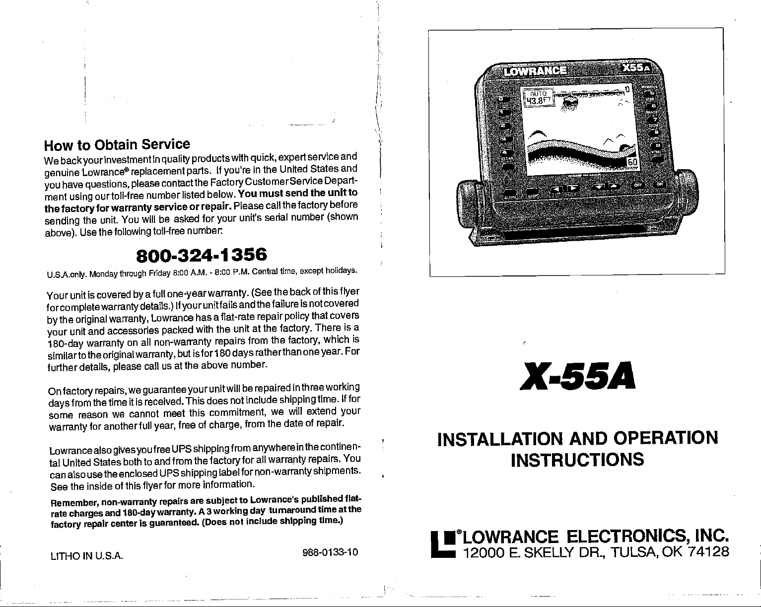
must send the
serial number
Central
the
(See
repair policy
at the
from the
ratherthan
be
repaired
include
we will
from the date of
anywhere
all
for
warranty
fornon-warrantyshipments.
turnaround
service and
States and
Depart-
unit to
the
factory
time, except holidays.
back of this
factory.
factory,
in
shipping
in
shipping
before
(shown
flyer
is not covered
that covers
There is a
which is
oneyear.
threeworking
extend
the continen-
repairs.
published
988-0133-10
For
time. If for
your
repair.
You
flat-
time at the
time.)
X-55A
INSTALLATION
INSTRUCTIONS
•®LOWRANCE ELECTRONICS,
12000
E. SKELLY
AND OPERATION
DR.,
TULSA,
OK 74128
INC.
PDF compression, OCR, web-optimization with CVISION's PdfCompressor
Page 2
INTRODUCTION
INSTALLATION
MOUNTING
POWER CONNECTIONS
TRANSDUCER
KEYBOARD BASICS
DISPLAY
MENUS
HELP
OPERATION
AUTOMATIC
SENSITIVITY
RANGE
and
Upper
ZOOM
Automatic
Manual
ALARMS
FISH ALARM
ZONE ALARM
DEPTHALARMS
ALARM MUTE
MENU
CHARTSPEED
GRAYLINE
FISH I.D
FISHTRACKTM
DISPLAY
MENU-PAGE2
ADJUST BACK
BACK LIGHT ON/OFF
SPEAKER
TURN
CONSTRUCT DIGITAL
MENU-PAGE3
CHARTCURSOR
DISPLAY ZOOM BAR
DISPLAY
DIGITAL SONAR
MENU-PAGE 4
FASTRAK
SELECT UNITS OF
CLEAR
MENU-PAGES
ADJUST
ADVANCED SIGNAL
WINDOWS
VIEWING
MODIFYING GROUPS
RESETrING
BROADVIEW
TRANSDUCERS AND
FISH ARCHES
SIGNAL INTERPRETATION
WATER
SURVEYING
BAIT FISH
TROUBLESHOOTING
WARRANTY
FREE UPS SNIPPING
MISSING PARTS
INTERNATIONAL SERVICE
Lower Limits
Operation
Operation
-
PAGE I
—
CONTRAST
LIGHT LEVEL
VOLUME
DIGITAL BOX OFF
ZONE BAR
DISTANCE LOG
CHART SURFACE CLARITY
WINDOWS OPTIONS
ALL GROUPS
TEMPERATURE AND THERMOCLINES
BOX
MEASURE
PROCESSING
CONE ANGLES
A LAKE
INFORMATION
Copyright®
All features and
1994
specifications
All screens in
..
(ASP)
Lowrance Electronics All
subject
this manual
to
change
are simulated.
rights
without
2l
reserved.
notice.
.2
.2
13
13
14
15
15
16
16
17
18
20
21
21
22
23
24
24
24
24
25
25
25
26
26
27
27
28
28
28
29
29
29
29
30
31
32
32
34
34
36
37
38
39
40
41
41
47
48
so
si
4
11
12
13
1
NOTICE!
This
product
onto the unit.
thisto
happen
watertight
The unit
bracket.
uses threaded
These nuts will
and
shouldn't be a cause
of the
integrity
unit.
won't raffle when
nuts inside
rattle
when
forconcern.
it's installed
53
the case to hold
shake
you
the unit, It's
This
With the
gimbal
the
gimbal
knobs
normal for
doesn't affectthe
knobs
onto its
PDF compression, OCR, web-optimization with CVISION's PdfCompressor
TABLE OF CONTENTS
Page 3
NOTES:
INTRODUCTION
The X-55A is a
second
the X-55A is
built. Thewide
detail. The
X-55A also
distancetravelled
ture,
(transom
to none in its class.
also one of the easiest-to-use
screen showsthe undetwaterworld
display
has
digital depth,
and
displays, you
log
mount)
high quality,
Using
and
keyboard
(log) displays.
orST-H
(through-hull
wide screen sonar with
features and
menu
sonars that Lowrance
with
are also
boat
In orderto
must
lighted
speed,
purchase
surface water
mount) speed/temperature
for
usethe
digital speed,
and install an
performance
"soft-key"
that is
operation,
has ever
resolution
high
night operation.
temperature,
tempera-
optional
sensor.
and
The
and
ST-T
SPECIFICATIONS
Dimensions
Transmitter
Transmitter
Transmitter Power
Display
The
storage temperature
Fahrenheit
temperatures
display
Frequency (all channels)
Power
(down channel)
(left
(-20 degrees
higher
in
your
unit. This
For more information,
or
TRANSOM
Hand-held" Drill with a
Two
Marine
local service
your
MOUNT TRANSDUCER
#12 stainless steel screws
(2)
grade caulking
&
right channels)
NOTICE!
for
your
to +75
degrees Celcius).
or lower than
of
type
contactthe
center.
TOOLS
variety
compound (to
damage
YOU WILL NEED:
of small bits
5 7/8"H x 7 3/4W x
192 kkz
600 watts
75
... 275 watts
34.4
Supertwist
128
20,
unit is from -4
specified
factory's
(to
will
is not covered
CustomerService
INSTALLATION:
attach bracket
seal
screws)
3
718"D
(p-p, typical)
watts
(RMS, typical)
(p-p. typical)
watts
(RMS, typical)
LCD
vertical x 160 horizontal
total
480
degrees
damage
pixels
to +167
Extended
the
liquid
the
by
Department
to the
degrees
storage
crystal
warranty.
transomS)
in
MOUNT:
package;
following epoxies:
Made
Power
by:
or PLASTIC WELDERTM
epoxy
epoxy.
Pox?
Adhesives,
Inc. or
epoxy
52
SHOOT-THRU-HULL
100
One
Power
True Value®
sold
Devcon®
sandpaper
grit
package
Poxft,
by
of the either of the
1 oz
brand TRUE BOND
True Value® stores or
brand PLASTIC WELDERTM
PDF compression, OCR, web-optimization with CVISION's PdfCompressor
Page 4
MOUNTING
Install the X-55A in
behind the unit when
convenient
any
it is tilted for the best
bracket base allow wood
to
place a piece
the
mounting
to attach the
of
plywood
hardware.
and
power
Make certain there is
transducer cables.
The smallest hole that will
the hole is
then
pass
drilled,
the
power
the transducer connector
pass
cable down
location,
screw or
through-bolt
on the back of thin
one
pass
power
through
provided
there is clearance
viewing angle.
mounting.
fiberglass panels
enough
room behind the unit
ortransducer
up through
it.
Holes in the
You
is 5/8". After
plug
the hole
need
may
to secure
first,
We back
Lowrance
Factory
may
You
your
replacement parts.
Customer Service
be able to solve the
will be asked for
Canada
How
investment in
to Obtain
(Canadian
quality products
If
you
Department
and save
problem
units
your
serial number.
Customers
need service or
at the
you
800-347-1014
Only. Monday through Friday
Service
Only)
with
quick, expert
toll-tree number listed below. A
the inconvenience
8:00 A.M.
repairs,
-
8:00 P.M. central
service and
contact the Lowrance
of
returning your
genuine
technician
unit.
Time,
After
routing
Offsetthe
and breakoutone of the
the
cables,
fill the hole with a
bracketto coverthe hole.
otherslots in the bracket
POWER CONNECTIONS
The X-55A works from a
attach the
cable to an
cable
power
accessory
twelve-volt
directly
or
power buss,
with electrical interference.
cable
power
#18
gauge
is the
positive
in-line
For
example,
attach one end of
buss,
This will
directly
wire onto it. The
fuse holderto the red lead as
protect
The X-55A uses a
Do not use this
Failure to use a
to the
black is
lead,
if
have to extend
you
thefuse
both the unit and
fuse.
3-amp
product
3-amp
without a
fuse will void
Routethe
battery system.
to the
battery.
however
Therefore,
battery.
power
negative
it's saferto
If the cable is not
cable hastwo
or
ground.
close to the
the
power
holderdirectlyto
the
power
IMPORTANT!
3-amp
your warranty.
marine
good
sealing compound.
powercablethrough
forthe transducer cable.
For the best
You can attach
you may
go
wires,
Make certain to
have
ahead and
long
enough, splice
red and
powersource
cable to the
the
cable in the
battery
batteryorpower
event of a short.
fuse wired into the
the slot
results,
the
power
problems
attach the
black. Red
attach the
as
possible.
or
power
cable!
power
buss.
How to Obtain
(International
If
need service or
you
WARRANTY
Please follow the
unitto the dealer. For
describing
daytime telephone
When
1.
2
3.
the
sending a product
use
Always
in when
shipping your product.
insure the
Always
assume
For
problem.
telephone
responsiblity
propertesting, repair,
To order accessories such
1. Your
2.
local marine dealer. Most
equipment
directory
canadian customers
Lowrance/Eagle canada,
for
repairs,
REPAIR WILL BE HONORED ONLY IN THE
shipping
problem.
instructions shown below on this
propertesting, repair,
Be sure to include
number.
Shipping
for
the
original shipping
parcel against
for
Be sure
number.
to include
Accessory Ordering
should be able to
listings.
only
Customers
contact the dealer in the
UNIT WAS
PURCHASED.
and
service,
your name,
Information
repair, please
goods
and
service,
your
as
power
assist
can write:
919 Matheson
or fax
do the
container and filler
or loss
damage
lost or
damaged
send a brief note with the
name, return
cables or
dealers that handle marine electronic
quality
with these items.
you
Blvd.,
416-629-3118
Service
Only)
country you purchased your
COUNTRY
if
page
send a brief
return
following:
material the
during shipment.
in transit
shipping address,
Information
transducers, please
consultyour
E.
Mississauga,
have to mail
you
note with the
shipping
address,
product
Lowrance does not
product describing
and a
contact:
local
Ontario L4W2R7
product
and a
was
packed
daytime
telephone
unit.
your
the
2
51
PDF compression, OCR, web-optimization with CVISION's PdfCompressor
Page 5
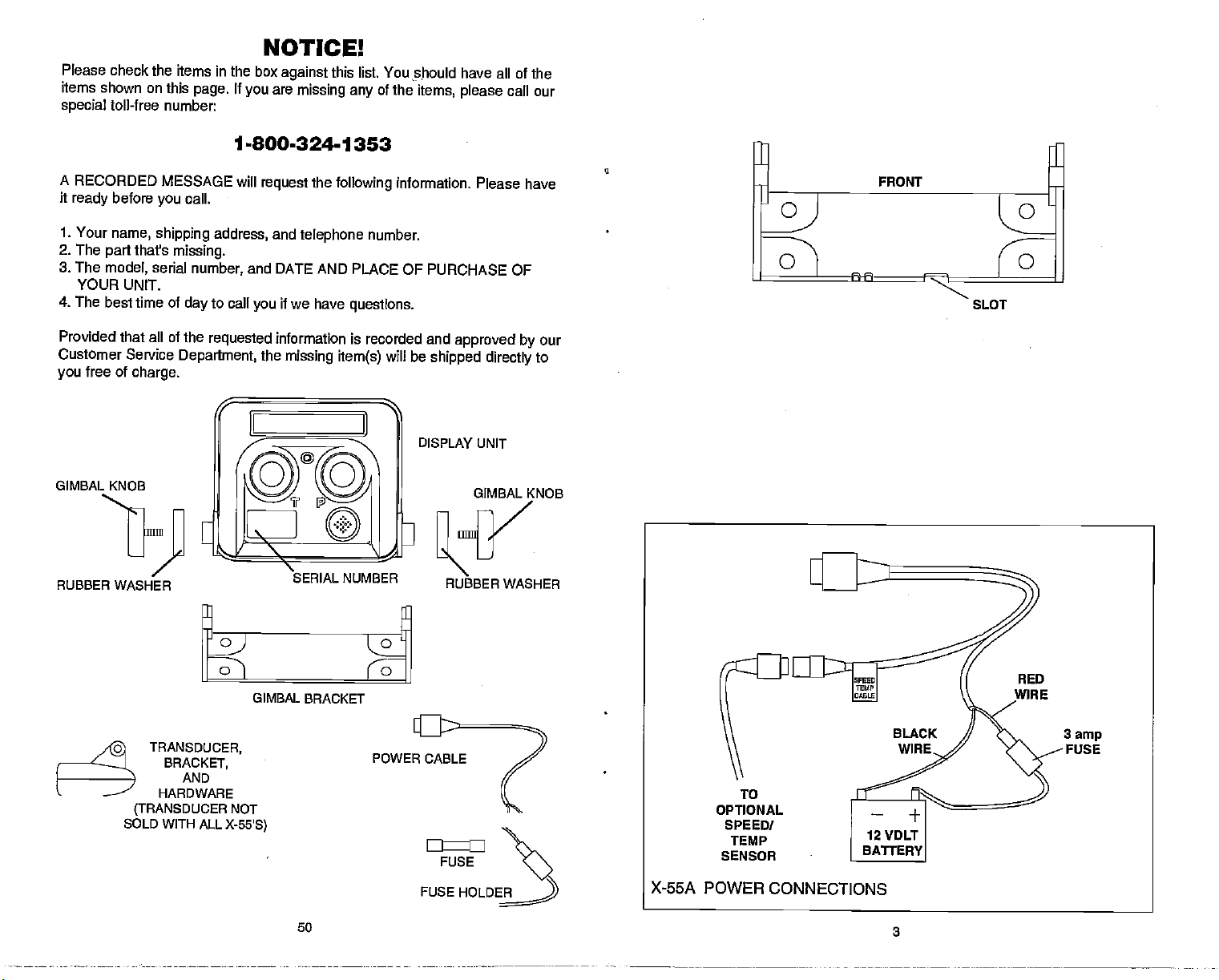
Please check the
items in the box
items shown on this
special
toll-free number:
NOTICE!
against
If
page.
are
you
missing any
1.800-324-1353
this list. You
of the
!hould
items,
have all of the
call our
please
A RECORDED MESSAGE
it
1. Your
2. The
3. The
4. The
Provided that all of
Customer
you
GIMBAL KNOB
RUBBER WASHER
before
ready
name,
that's
part
model,
YOUR UNIT.
best time of
Service
free of
charge.
call.
you
shipping
missing.
serial
number,
day
the
Department,
address,
to call
requested
will
request
and
telephone
the
following
number.
and DATE AND PLACE OF
if we have
you
information is recorded
the
missing item(s)
questions.
will
information.
PURCHASE OF
and
approved by
be
shipped directly
DISPLAY
RUBBER WASHER
Please have
our
to
UNIT
GIMBAL
KNOB
SLOT
RED
GIMBAL BRACKET
o
TRANSDUCER,
BRACKET,
AND
HARDWARE
(TRANSDUCER
SOLD WITH ALL
NOT
X-55'S)
50
POWER CABLE
FUSE
FUSE
HOLDE)
X-55A
OPTIONAL
SPEED!
TEMP
SENSOR
POWER CONNECTIONS
3
3
PDF compression, OCR, web-optimization with CVISION's PdfCompressor
Page 6
TRANSDUCER
Some X-55A's are sold with a HS-WSBK
can be installed on
ered boat.
through1'
The
strikes
up",
If
your
attempting
right
the
hull,
cannot
critical
perform
Location
The transducer must be
1.
It can also be
the hull on some
"kick-up" mounting
an
object
bracket can
the
unit came with a
the installation. Determine
for
boat. Use extreme
your
since once it is
be removed.
of a sonar installation.
part
at it's
designed potential.
-
General
outboard or stern-drive
any
permanently
fiberglass
bracket
helps prevent
while the boat is
be
easily
Remember,
pushed
transducer,
epoxied
placed
installed
boats.
moving.
back
read this section
which of the
care if
into
the transducer location
If it isn't done
in a location
water at all times. If the transducer
the chosen location must
then
transducer is not
placed
show on the sonar's
whenever the boat is
display
moving.
be in the water at all times.
in a smooth
in the form of random
transom mount transducer. It
(inboarcf\outboard) pow-
inside the boat to "shoot-
damage
if the transducer
If the transducer does "kick-
in
mounting
position,
without tools.
place
carefully
mounting positions
the transducer
the transducer
before
inside
usually
is the most
properly,
that has a smooth
is to be mounted inside
flow of
water,
the sonar
flow of
the
interference will
lines or dots
is
can't
hull,
If the
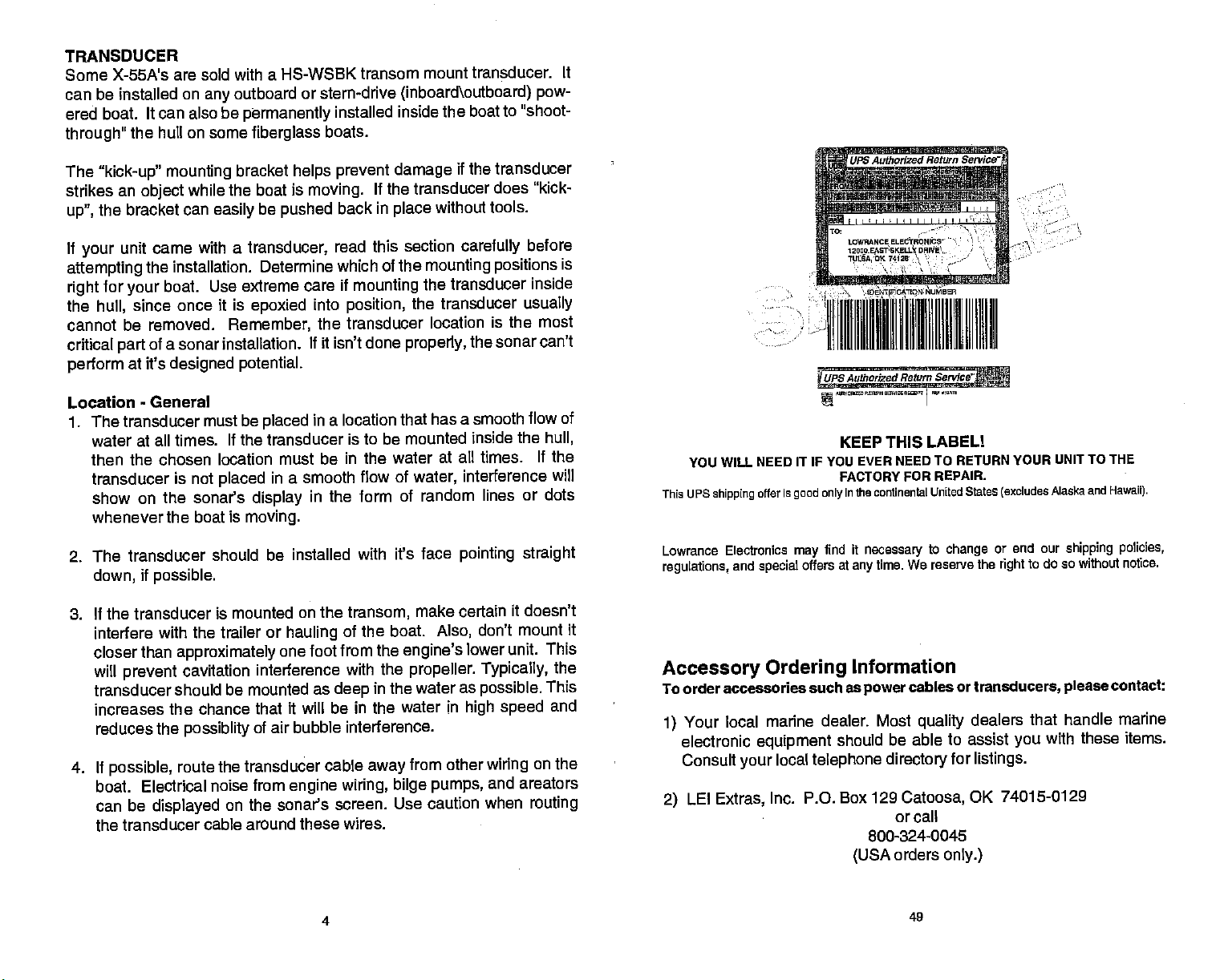
YOU WILL NEED IT IF YOU
This us
shipping
offer Is
Authorized Return Sent
UPS
TO
LOWOANCE
12000
EStSKELQY
OK 74120
ILILSA,
,Dè1rp010Ar,ON
ELEOThONICS
1 III tII IllhIll lluI
UPS Authorized Return
KEEP THIS LABELl
EVER NEED TO RETURN YOUR
FAcToRY FOR REPAIR.
continental united states
good only
In The
'II.tI
DONE1
uMe0H
Sen'icej
(excludes
UNIT TO THE
Alaska and Hawaii).
2. The transducer should be
if
down,
possible.
3. If the transducer is mounted
interfere with the trailer or
closer than
will
prevent
transducer
increases the chance
reduces the
4. If
possible,
boat. Electrical noise
can be
approximately
cavitation interference
should be mounted as
possiblity
route the
displayed
on the sonar's screen. Use
one
that it will be in the water in
of air bubble interference.
transducer cable
from
the transducer cable around
installed with it's face
on the
transom,
hauling
of the boat.
foot from the
with the
deep
engine wiring, bilge
engine's
in the
away
make certain
propeller.
water as
from other
pumps,
caution when
these wires.
4
pointing straight
it doesn't
don't mount it
Also,
lower unit. This
Typically,
possible.
high speed
wiring
and areators
the
This
and
on the
routing
Lowrance Electronics
and
regulations,
Accessory
To order
Your local marine
1)
electronic
Consult
LEI
2)
special
Ordering
accessories such as
equipment
local
your
Extras,
Inc. P.O. Box 129
find It
may
offers at
necessary
time. We reserve the
any
Information
power
dealer. Most
should be able to
telephone directory
Catoosa,
or call
800-324-0045
orders
(USA
to
cables
quality
only.)
49
or end our
change
or
transducers,
dealers
assist
for
listings.
OK 74015-0129
to do so without notice.
right
that handle marine
you
shipping policies,
contact:
please
with these items.
PDF compression, OCR, web-optimization with CVISION's PdfCompressor
Page 7
Lowrance's UPS Return
Lowrance
all of
If
you
United
to our
1
.Call Lowrance atthetoll-free numberonthefrontof
Authorization
return. Do not return a
Authorization
2.
Pack
possible.
tion!
Electronics and United Parcel Service
ourcustomersfreeshippingforall
have
to send this unit to the
States,
factory
your
usethe enclosed UPS
customer service
number and instructions about what accessories to
(IRA)
Number!
(RA)
unit and
Be sure to include
any
Service
unitssentto
factory,
department.
product
accessories in the
proof
and
shipping
to the
of
purchaseforwarrantyverifica-
(UPS)
you
label
There are six
factory
original shipping container,
are
usforrepairorservice.
are in the continental
foreasy,
thisflyerfora
to offer
proud
free
shipping
easy steps:
Return
without a Return
if
Shoot-thru-bull v,s, Transom
Typically,
tion and
damage
loading
However,
some loss of
from hull to
is caused
of the transducer cannot be
be a
slow
installation section in this manual to determine if
shoot
shoot-thru-hull installations
to excellent
good
from
floating objects.
on the trailer.
the shoot-thru-hull installation does have its drawbacks.
sensitivity
even
hull,
differences in hull
by
problem
trolling speeds.
through
on some hulls that sit with the bow
the hull.
does
from different installations on the same hull. This
Follow the
Mounting
depth capability.
It can't be knocked off when
occur,
layup
adjusted
procedure
excellent
give
There is no
even on the best hulls. This varies
and construction.
for the best
listed in the shoot-thru-hull
high speed opera-
possibility
docking
One,
the
Two,
fish arches. This can
when at rest or at
high
can
you
satisfactorily
angle
of
or
3. Write a brief note
Please include
4. Please include
or MasterCard
Visa,
5. Fill in
6.Attach the label to the
That's it! Your unit will
department
is 3
Lowrance will
factoryforthis
loss or
your name, address, zip code, date,
provided
give
Customer Center.
on the UPS
the
package
at no
working
days.
unit in the event it needs
shipping damage
detailing
your name, address,
payment
may
form included with
to
any
You will not be
charge
Units
underwarrantywill
UPS surface
pay
the
problem you're having
and
for
non-warranty repairs.
be used.
your
tear off the tab for
shipping
be
to
when
box,
UPS driver or take the
charged
shipped
you.
to Lowrance's customer service
Our normal
NOTE!
shipping charges
use the enclosed UPS label.
you
in-plantturnaround
be returned
repair.
with
the unit.
daytime
and RA number in the blanks
telephone
Check,
unit.
package
for this
shipment.
toyou
both to and from the
Yourunit is insured
number.
to
any
on
at no
order,
repairs
charge.
against
money
your receipt
and
UPS
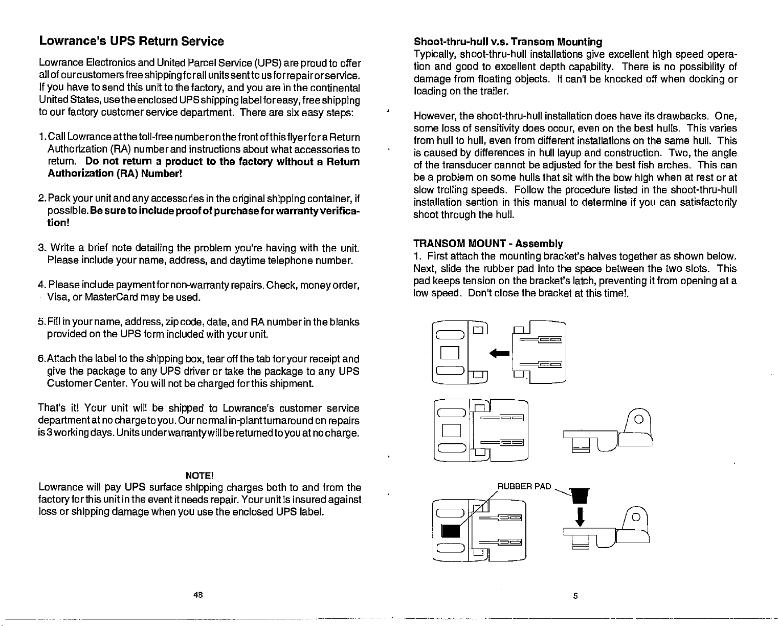
TRANSOM MOUNT
1. First attach the
slide the rubber
Next,
pad keeps
low
tension on the bracket's
speed.
_
mounting
Don't close the
_
RuBBER PAD
-
Assembly
bracket's halves
into the
pad
bracket at this time!.
as shown below.
it from
space
latch,
together
between the two slots. This
preventing
EJ
opening
at a
Lb=H
48
PDF compression, OCR, web-optimization with CVISION's PdfCompressor
5
Page 8
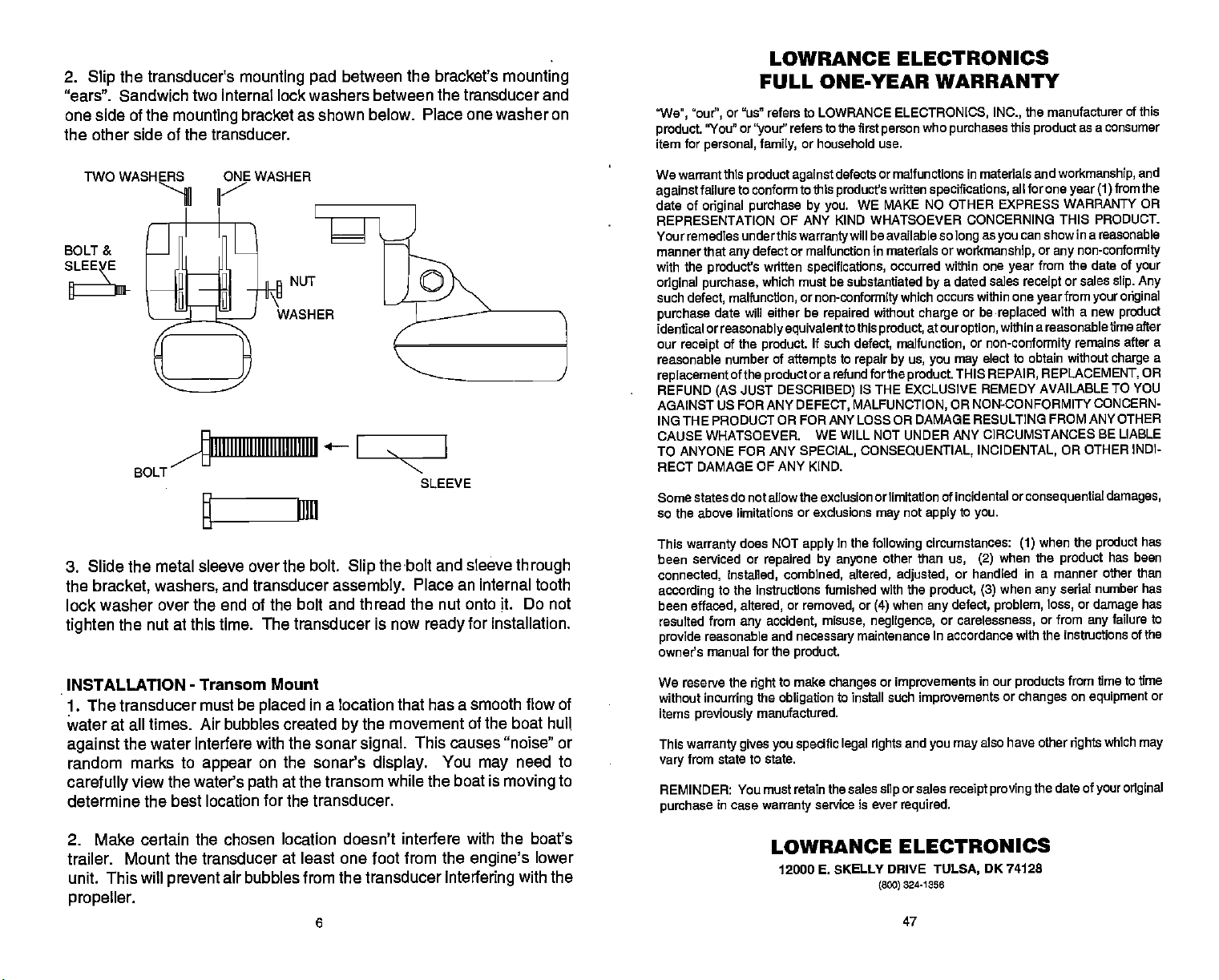
2.
the transducer's
Slip
mounting pad
between the bracket's
mounting
"ears". Sandwich two internal lock washers between the transducer and
one side of the
mounting
bracket as shown below. Place one washer on
the other side of the transducer.
TWO WASHI
BOLT &
BOLT
3. Slide the metal sleeve over the bolt.
the
bracket, washers,
lock washer over the end of the bolt and
tighten
INSTALLATION - Transom
1. The transducer
water at all times. Air bubbles created
against
random
carefully
determine the best location for the transducer.
the nut at this time.
must be
the water interfere with the sonar
marks to
appear
view the water's
WASHER
WASHER
III 1111111111111111111111 I
11111
and transducer
The
transducer
Mount
placed
on the sonar's
at the transom while the
path
SLEEVE
the bolt and sleeve
Slip
assembly.
Place an internal tooth
thread the nut onto it. Do not
is now
for installation.
ready
in a location that has a smooth
the movement of the
by
signal.
This causes "noise" or
display.
You
boat is
boat
may
moving
through
flow of
hull
need to
to
LOWRANCE ELECTRONICS
FULL ONE-YEAR
'We", "our",
product.
item for
We warrant this
against
date of
REPRESENTATION
Your remedies under this
manner that
with the
original purchase,
such
purchase
identical or
our
reasonable number of
replacementof
REFUND
AGAINST
ING THE PRODUCT OR FOR ANY LOSS OR DAMAGE
CAUSE WHATSOEVER. WE
TO
RECT DAMAGE OF ANY KIND.
Some states do not allow the exclusion or limitation of incidental
so the above limitations
This
been serviced
connected,
according
been
resulted from
provide
owner's manual for the
We reserve the
without
items
This
vary
REMINDER: You must retain the sales
purchase
or "us" refers to LOWRANCE
"You" or
personal, family,
failure to conform to this
original purchase by you.
any
product's
malfunction, or
defect,
date will either be
reasonably equivalentto
of the
receipt
JUST
(AS
US FOR ANY
ANYONE FOR ANY
warranty
does NOT
installed, combined, altered,
refers to the first
"your"
or household use.
product against
OF ANY KIND WHATSOEVER CONCERNING THIS PRODUCT.
defect or malfunction in materials or
written
which must be substantiated
product
attempts
the
product
DESCRIBED)
or
repaired by anyone
defects or malfunctions
product's
WE MAKE NO
warranty
will be available so
specifications,
non-conformity
repaired
If such
without
this
defect, malfunction,
to
repair by us, you may
ora refund forthe
IS THE EXCLUSIVE
DEFECT,
SPECIAL, CONSEQUENTIAL, INCIDENTAL,
or exclusions
apply
MALFUNCTION,
WILL NOT UNDER ANY CIRCUMSTANCES
may
in
the
following
to the instructions fumished with the
or
effaced, altered,
any
reasonable and
right
incurring
previously
warranty gives you specific legal rights
from state to state.
in case
removed,
accident, misuse, negligence,
necessary
product.
to make
the
obligation
manufactured.
warranty
or
(4)
maintenance in accordance with the instructions of the
changes
to install such
service is ever
person
product,
other than
or
slip
WARRANTY
ELECTRONICS. INC.,
who
purchases
in materials and
written
specifications,
OTHER EXPRESS WARRANTY OR
as
long
occurred within one
which occurs within one
not
adjusted,
when
improvements
and
or sales
required.
workmanship,
a dated sales
by
or be
charge
atour
option,
or
non-conformity
elect to obtain without
THIS
product.
apply
circumstances:
REPAIR,
REMEDY AVAILABLE TO YOU
OR NONCONFORMITY CONCERN-
RESULTING FROM ANY OTHER
to
you.
us,
(2)
or handled
product, (3)
defect,
any
or carelessness,
in our
improvements
you may
also have other
receipt proving
the manufacturer
this
product
workmanship,
all for one
you
year
replaced
within a reasonable time after
or
(1)
when the
when
problem,
products
or
changes
year (1)
can show in a reasonable
or
any
from the date of
or sales
receipt
from
year
with a new
remains
REPLACEMENT,
OR
consequential damages,
when the
product
in a manner other than
serial number has
any
loss,
or from
from
on
rights
the date of
of this
as a consumer
and
the
from
non-conformity
your
slip. Any
your original
product
after a
charge
BE LIABLE
OTHER INDI-
has
product
has been
or
damage
failure to
any
time to time
equipment
which
may
your original
a
OR
has
or
2. Make certain the chosen location doesn't interfere
trailer. Mount the transducer at least
unit. This will
prevent
air bubbles from the transducer
one foot from the
with the boat's
engine's
interfering
with the
lower
LOWRANCE ELECTRONICS
12000 E SKELLY DRIVE
(800)
324-1358
TULSA,
OK
74128
propeller.
6
47
PDF compression, OCR, web-optimization with CVISION's PdfCompressor
Page 9
0$11:
FEET
I
I
45.2
..
ni
fl-I
:1:
—
—
—
— —
— —
°
12
24
36
CLAMP ThE TRANSDUCER CABLE TO
TRANSOM NEAR THE TRANSDUCER. This
WILL HELP PREVENT
FRDM ENTERING ThE
KNOCKED OFF AT HIGH SPEED.
CAUTIONI
TIlE TRANSDUCER
BOAT IF IT IS
65.4
GROUP "I"
;;i°
63.5°F
I ,—.
100
-
rt.i1itiia
OFT
jnflu!
100FT
GROUP "K"
if
100
-5;7r$
ii_______ik'
635°F__JL
I:T'sflg:;'
&JOLTS I
I
12.6
GROUP "M"
\
100
e
GROUP Uji
— 0$ i : 'JDI M
I FEET I
5O.2
-I-&o
I MPH I
II
5.4
• I '4$ :f'MuJi4 tewi Ulu
GROUP "L"
iooll
•flI;I'4$:) III ;s.i
GROUP "N"
100
;cj;dU
ICR LOCATION
GOOD LOCATION
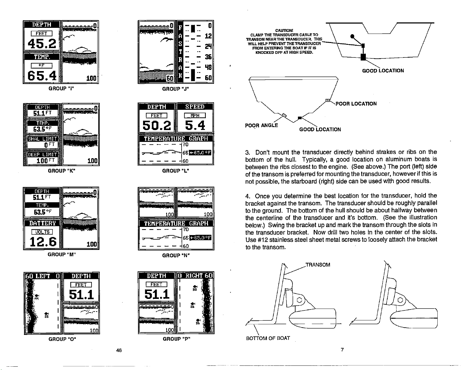
3. Don't mount the transducer
bottom of the hull.
between
of the transom is
not
4. Once
bracket
to the
the centerline of the transducer and it's bottom.
below.) Swing
the transducer
Use #12 stainless
to the transom.
the ribs clpsest to the
possible,
ground.
the starboard
you
against
Typically, a good
preferred
determine the best location for the
the transom. The transducer should be
The bottom of the hull should be about
the bracket
bracket. Now drill two holes in the center of the slots.
steel sheet metal screws to
directly
engine. (See
for
mounting
side can be used with
(right)
and mark the transom
up
behind
location on aluminum
above.)
the
transducer,
loosely
strakes or ribs on the
boats is
The
port (left)
however if this is
good
transducer,
roughly
halfway
the
(See
through
attach the bracket
side
results.
hold the
parallel
between
illustration
the slots in
:i
I
I
'
k
r
GROUP "0" GROUP "P'
51.1
I
thJSgSthSTt0
I
I
u:e:
FEET I
.•.
100
46
o*an I•:4ftbk!
I FEET I
.JI
51.1
jrciw"'O
:'
'
l
I
100
BOTTOM OF BOAT
7
PDF compression, OCR, web-optimization with CVISION's PdfCompressor
Page 10

5.
Adjust
is
slightly
manual for
Don't
Overtightening
the transducer to
together by pressing
attached) against
Clamp
This
off at
the transducer and
lower than the
proper
overtighten
the transducer cable to
will
prevent
high speed.
transducer
the bolt
the bolt
"kick-up"
the one screwed to the transom.
the transducer from
bracket so that the front of the transducer
back. See the section on fish arches in this
angles. Tighten
that holds the transducer to the bracket.
result in a distorted bracket which will allow
may
at
high speed.) Snap
the outer bracket
IMPORTANT!
the transom close to the transducer.
entering
all screws.
the transducer bracket
one with the transducer
(the
the boat if it is knocked
(CAUTION:
,0
-
sr
0.01
t*a
MPH
0.0
.Qjj
0.OMI 100
GROUP
ja:• ani;ra
I FEET I I I
45.2 65.4
— 2D$ DI I
MPH
5.4 2.0
GROUP "C"
"A"
IMILESI I
I
F
GROUP "B"
GROUP "D"
H,
J
FLAT-BO1TOM HULL DEEP-"VEE" HULL
NOTE: Some aluminum boats with strakes or ribs on the outside of the
hull create
typically
speeds
the hull as
of the transducer below the turbulent
work at
6. Route the transducer cable to the sonar unit.
cable
from
up
unwanted interference
7. Make a test
there is interference on the
the boat at
transducer's bracket as shown at
have
over 35
possible
high speeds.
away
engine wiring
on the transducer cable. This can show
amounts of turbulence
large
outboard motors
large
The
mph.
on these boats.
from other
or
run
high speed,
transducer should be mounted as far below
wiring
bilge pumps
on
the sonar
to determine the results. If
display
at
high speed.
capable
(See below)
water,
on the
try lowering
boat,
can be
display.
when
right.
8 45
of
allowing
if
possible.
picked
as
up
running
the
propelling
This will
Keep
These boats
the boat at
the face
place
the sonar unit to
the transducer
Electrical noise
OMih:•
FEET
I
51.1
r
I JOLTS I
12.6
I
T—.
100
GROUP "E"
Cr
r
GROUP "G"
GROUP
"P
a
100 100
GROUP "K"
PDF compression, OCR, web-optimization with CVISION's PdfCompressor
Page 11

If
find noise interference from an electrical
you
or
pump,
unit's
causing
transmitting,
need
it from other
If no noise
certain
Increase the RPM with the
display,
or tachometer
routing
routing
problems.
wiring
When no noise
the noise source is
limited
in shallow
radio, tryto
power
the interference. VHF radio antenna cables radiate noise when
so be certain to
to
route
wiring
displays
everything exceptthe
the
problem
the sonar unit's
the
power
Make certain to use the in-line
the
power
experience
water,
isolatethe
cable and transducer cable
the sonar unit's
on the boat.
on the sonar unitfrom
could be one of three
wiring. Try using
cable
cable to the
appears
probably
make
problem.
keep
power
sonar unit is turned
gearshift
resistor
power
cable
directly
battery.
on the sonar unit after all of the
cavitation.
sonar installations
hasty
You can
the sonar's wires
cable
electrical
in neutral. If noise
spark
away
to the
fuse
Many
or when the boat is at rest. In
away
directly
things; spark plugs,
battery helps
of the malfunction will be the location and/or
face of the transducer must be
of water at all boat
best
mounting position.
speeds.
Read
placed
in a location that
transducer owner's
your
instrument,
usually
from the
away
to the
equipment,
off,
plugs,
from
engine wiring. Again,
supplied
novices or
which function
nearly
of the transducer.
angle
trolling
reroutethe sonar
from it. You
battery
then startthe
appears
alternator
eliminate noise
with the unit when
above
all
cases,
has a smooth flow
manual for the
wiring
to isolate
then make
engine.
alternator,
filters,
tests,
persons
perfectly
the cause
motor,
that is
may
on the
or
then
with
The
SHOOT-THRU-HULL INSTALLATION
The transducer installation inside a
that does not have air bubbles in the resin or
layers.
ful
(such
The sonar
transducer installation oan be made on hulls with flotation materials
as
plywood,
signal
balsa
must
wood,
fiberglass
pass through
or
foam)
hull must
solid
between
separated fiberglass
fiberglass.
layers
the material is removed from the chosen area. For
manufacturers
finishing
fiberglass
The transducer can then
After
glass.
Remember,
bubbles in the
signals.
To choose the
60 feet of water.
transducer into the sonar
FILL WITH
use a
with an outer
and the balsa wood core
the
epoxy
sonar
the
fiberglass
proper
Add a little water to the
of
layer
layer
cures,
signal
location for thru-hull
fiberglass,
of
fiberglass. Removing
exposes
be
epoxied directly
the hull is
must
or the
unit,
turn it
watertight
through
pass
will reduce or eliminate the sonar
epoxy
on,
then a core of balsa
the outer
to the outer
and
solid
mounting,
of the boat.
sump
then hold the transducer over
be in an area
A success-
of
fiberglass
example,
the inner
of
layer
structurally
fiberglass. Any
anchor the boat in
INNER HULL
fiberglass.
of fiber-
layer
Plug
EPOXY,J?1
)
—
-a
some
wood,
layer
sound.
the
if
of
air
FIRST—
Adjust
is seen on the
Next,
sump
and the bottom
greatly
outside of the hull. If
the hull the best and follow
the
sensitivity
display. (you
units.)
take the transducer out of the
Don't touch the controls once
of the boat. Observe
sensitivity.
signal may
to
compensate,
mounting.
location. If the
not,
9
OUTER HULL
and
the sonar
The second
decrease in
then
then mark the location that
the instructions on the next
controls until a
range
will need to turn the
water and
to see if
signal
bottom
intensity.
sensitivity
the transducer should
place
signal
Move
control
it
WINDOWS SUMMARY
All of the window
pages.
repeated press
groups.
will revert to the ones shown on these
To view these
Remember,
groups
the down arrow
used
groups, simply press
each
group
the X-55A are shown on the
by
key.
can be
44
This will
customized,
pages
WINDOWS
the
"cycle"
when
the unit
however the
the unit is turned off.
following
then
key,
through
group
all
Epoxy TO HULL
the side of the boat.
second bottom echo
automatic function off on L.C.G.
they've
been set.
in the water in the
there is a noticeable decrease in
may disappear
the transducer around to find the best
has to be increased
be mounted on the
shot
through
for a shoot-thru-hull
pages
PDF compression, OCR, web-optimization with CVISION's PdfCompressor
Page 12

TRANSDUCER
(HIGH SPEED) (TROLLING SPEED)
LOCATION TRANSDUCER LOCATION
2. Electrical noise from the boat's motor can interfere with the sonar. This
causes the sonar to
rejection
feature. This can
automatically
cause the unit to eliminate weaker
as fish or even structure from
routing
electrical
the sonar unit's
on
wiring
the boat.
power
increase its Discrimination or
signals
the
display. Try using resistorspark plugs
and transducer cables
away
noise
such
or
from other
No fish arches when the Fish ID feature is off:
1. Make certain
common
in
your
problem
owner's manual for more information.
transducer is
if a
partial
arch is
pointing straight
displayed.
down. This is the most
See the Fish Arch
section
Shoot-thru-hull
1. Make certain the area is
Installation
clean.
and free of oil or
dry.
grease,
then
2. The
a fish
sensitivity may
it has to be able to receive the fish's echo from the time it enters
arch,
the cone until it leaves. If the
the fish
when it is in the center of the cone.
only
not be
sensitivity
high enough.
is not
In order for the unit to
high enough,
the unit
display
displays
sand both the inside surface of the hull and the face of the transducer
with 100
grit sandpaper.
transducer face is in contact with the hull
SAND THIS SURFACE
2. Follow the instructions on
Do not mix it too
(NOTE!
Use
only
the
to use one of these
a small amount on the face of the transducer as shown
Apply
then
spread
a small amount onto the sanded area on the hull. Place
The surface of the hull must be flat so the entire
to
prior
SPREAD
the
epoxy package
as it will cause bubbles to form in the
fast,
epoxies specified
epoxies may
on
result in
10
page
bonding.
1 of this
poor
and mix it
manual! Failure
sonar
performance!)
thoroughly.
epoxy.
above,
the
3. Use the Zoom feature. It is much easier to
zoomed in on a small
will have much better
a 0 to 60 foot
range.
This
Iuckseeingfish
of water than a
range
enlarges
large
archeswith a SOto 60 foot
the
targets, allowing
much more detail.
4. The boat must be
the boat is
straight
NOISE
A
major
on the sonar's
it can
operate erratically,
motionless,
horizontal lines.
cause of sonar
display
completely
cover the screen
moving
or not at all.
at a slow
fish
stay
problems
as random
trolling speed
in the
cone, showing
is electrical noise. This
patterns
of dots or lines. In
with black
To eliminate or minimize the effects of electrical
the cause. With the boat at rest in the
is turn all electrical
also. Turn
off,
Processing).
turn on each
on the sonar's
sonar
display
equipment
your
There should be a
of
piece
display.
for noise. If no noise is
on theVHF radio and
has been turned
on,
X-55A
electrical
For
transmit.
theireffecton the
on the boat off. Make certain the
then turn off ASP
on,
steady
equipment
example,
Keep doingthis
43
turn on the
present,
sonardisplay
the first
water,
bottom
on the boat and view the effect
turn the
until all electrical
display
noise, firsttryto
signal
fish arches when
one. For
example, you
the
display
rangethan
to see fish arches. If
on the
or cause the unit
dots,
thing you
(Advanced Signal
on the
bilge pump
pump
noted,
display
usually appears
severecases,
determine
should do
display.
and view the
off,
equipment
then turned off.
to show
as
engine
then turn
is
Now
PDF compression, OCR, web-optimization with CVISION's PdfCompressor
Page 13

terminals or
charging.
Unit
freezes,
1. Electrical noise from the boat's
be
may
cables
sonar unit's
block or
2.
interfering
away
ignition
Inspect
power
the transducer cable for
3. Check both the transducerand
securely plugged
Weak bottom
1. Make certain
transducer.
reducing
sure it
bonded tothe hull. Do NOT use RTV silicone rubberadhesiveorMarinetex
Oil, dirt,
its effectiveness. If the transducer ismounted inside the
is
shooting through only
on the terminals are
wiring
locks
up,
or
operates erratically:
with the sonar unit.
from other electrical
cable
switch
in to the
echo,
transducer is
directly
unit.
digital readings
pointing straight
and fuel can cause a film to form on the
one
corroded,
motor, trolling motor,
Rerouting
wiring
to the
battery
breaks, cuts,
powerconnectors.
erratic,
the
on the boat
instead of
or
or no fish
down. Clean the face of the
layerof fiberglass
or the
battery
or an
powerand
may help.
through
pinched
needs transducer into the
accessory
transducer
Route the
a fuse
wires.
Make certain both are
signals:
transducer,
be
hull,
and that it is
securely
2. Electrical noise from the boat's motor can interfere with the sonar. This
causes the sonar to
rejection
feature. This can cause the unit to eliminate weaker
automatically
as fish or even structure from the
increase its Discrimination or noise
signals
display.
such
epoxy, twisting
and
turning
out from under the transducer face. The
be
parallel
hull and transducer. After the
KEYBOARD
The
row at the bottom. The
and menu selections. The
feature and the basic sonar functions. The menu
corner of the
bottom of the screen are used
and make menu selections with the arrow
WINDOWS
customize
you
SENS - Press this
RANGE
mode.
ZOOM - The X-55A
with the
keyboard
-
-
This
hull,
has
keys arranged
keyboard
This
key
displays.
key
lets
key
gives you
with a minimum amount of
epoxy dries,
in two
vertical columns
in the left column are used to enter numbers
keys
in the
keys
activates the first
right
to activate the alarm
you
adjust
access to the windows
the unit's
the
range
gives
to
you adjust
2X and 4X zoom
it to force
face of
menu
keys.
sensitivity.
when the unit is in the manual
the
route the
column activate the windows
key
page.
capability
AUTO - This turns the automatic feature off and on.
air bubbles
any
transducer should
between the
epoxy
cable to the
plus
X-55A.
a
horizontal
in the bottom
The
keys along
menu, stop
mode,
the
which lets
with this
right
the
chart,
key.
3. The water
the sonar can't find the bottom
will flash
digital
thanthewateryou
then
change
increase the
should
appear.
4. Check the
also
power
Bottom echo
weak bottom echo while boat is
1. The
smooth flow of water in order for the sonar to work at all boat
bubbles in the water
find the bottom or
transducer
be
may
deeper
continuously.
are in. If this
the
sensitivity. Asyou
battery voltage.
range
to a realistic
drops, reducing
disappears
may
other
at
be in turbulent water. It must be mounted in a
disrupt
targets.
than the sonar's
while it's in the automatic
signal
It
may change
happens, placethe
move
into
If the
voltage drops,
its
ability
high speeds
the
one, (for example,
shallowerwater,
to find the bottom or
or erratic
to find the bottom. If
ability
to limits far
range
unit in the manual
0-100
a bottom
the unit's transmitter
targets.
digital reading
moving
the sonar
signals, interfering
with its
The technical term for this is Cavitation.
42
mode,
greater
mode,
feet)
signal
speeds.
ability
the
and
or
Air
to
MENU - Press this
functions.
CLEAR
ALARM
STOP - When this
affect the
-
This
key
-
Press this
digital display,
ARROW KEYS - These
move
objects
-
ON
The ON
-
OFF
Press and HOLD the Off
on the screen.
turns the X-55A on.
key
to show the menus
key
and
access to most
gain
clears menus and erases entries from the screen.
key
key
to activate
is
pressed,
however.
are used to make menu selections and to
keys
key
of the sonar alarms.
any
the chart
stops scrolling.
to turn the X-55A off.
11
This doesn't
PDF compression, OCR, web-optimization with CVISION's PdfCompressor
Page 14

DISPLAY - General The most efficient
The
firstturned on. Menus
the
display
the
disappear
CLEAR
are turned on for
lights
adjacent
key
and
keyboard.
will
lights
after ten
at the
key
approximately
appearatthe
to the
Light
If
you
automatically
seconds,
bottom of the
ten seconds when the X-55A is
sametime. To
label. It controls the
don't wantthe
turn themselves off. The
or
can turn them off
you
screen.
lights
keep
backlighting
waitten seconds and
on,
the
lights
used on the
menus will
by pressing
on,
press
also
the
survey
indicate the
As
it with
you go
your
promising spots
about
of bottom. It will also reveal
a few marker
Keep
X-55A indicates a school of
The Metric label at the
key adjacent
This also
knots,
to the Metric label to
changes
and
log
the
to kilometers on the X-55A.
of the screen works the same
top
change
temperature display
the
to
depth
degrees
Press the
way.
from feet to meters.
Celsius, speed
to
marked,
This is essentialwhen
spot.
can make
you
mark the school of fish when
again.
to become
way
X-55A. Start with a
in relation to landmarks
your survey, your
suspended
in the
buoys
yourturn
boat,
throw the
fish,
and come backto fish
you're
you're
acquainted
map
X-55A will tell
fish.
ready
with a
of the
lake,
you
to toss overboard. When the
out. With the school thus
buoy
farfrom shore on a
over
it, you may
of water is to
body
if
possible,
and
on shore.
the
in
lake.
big
not be able to find it
and
depth
type
exactlythe right
Unlessyou
The
Display
contrast for the best
the
contrast,
best
viewing angle,
approximatelyten
menu at the bottom of the screen lets
viewing angle. Pressing
the
arrow increases it. After
right
press
seconds and itwill
the CLEAR
automatically
the left arrow
setting
to erase the menu
key
you
erase. See the
Contrast section for more information on this feature.
When the X-55A
at left. The word "AUTO" in the
the automaticfeature is on. The
is
firstturned
the
on,
upper
digital
displaywill appear
left corner of the
bottom
depth
also shows
adjustthe display's
decreases
key
the contrast
for
the
or
wait
Display
similarto the one
display
indicates
in
this box.
BAIT FISH
The
importance
are the
They
Bait fish are the
can also be the
They
bass.
of baitfish to successful
principle
food of all
plankton feeding forage
of
young
game fish,
Most bait fish concentrate within
promotes
fishing
off,
fish
TROUBLESHOOTING
If
your
following
service
the
growth
is to use the X-55Ato find the bait fish first. With the Fish ID feature
a school of bait
will be
nearby,
unit is not
troubleshooting
department.
of the
plankton
fish will look like a "cloud" on the
often
directly
working,
or if
section before
It
save
may
Unit won't turn on:
1. Check the
2. Make certain the
to the
positive battery terminal,
cable's connection at the unit. Also check the
power
cable is wired
power
game
fishing
fish in most
can't be
such as minnows and shad.
fish,
as
such
overemphasized.
waters.
crappies, bluegill,
five feet of the surface where
on which
beneath the school of bait fish.
need technical
you
contacting
the trouble of
you
properly.
black to
negative
feed. One method of
they
display. Usually, game
help, please
the
factory
returning your
The red wire connects
or
ground.
and
sunlight
use the
customer
unit.
wiring.
3. Check the fuse.
4. Measure the
at least 11 volts. If it
12 41
battery voltage
isn't,
at the unit's
the
wiring
power
to the unit is
connector. It should
defective,
the
be
battery
PDF compression, OCR, web-optimization with CVISION's PdfCompressor
Page 15

MENUS
The X-55A uses menus ex-
J4flPS/A?
83°
78°
tensivelyto guide
the functions and features
the unit.
cesses
tures, allowing
ize the unit to
needs and water conditions.
Although you may
The menu
many
you through
of
ac-
key
of these fea-
to custom-
you
your particular
have to
leave one menu and enter
another to reach the desired
77°
760
75°
680
function,
press
all
the menu
simply press
HELP
An
extremely
menus.
gives
example, pressing
Virtually every
one or more
unit into or out of the
screen.
Pressing
of how automatic works and
have to do is
you
to select the next
key
the CLEAR
useful feature
feature has a
pages
the AUTO
automatic mode. A
the
key adjacentto
menu. If
key.
incorporated
of text
describing
into the X-55A series is the
menu label
help
key brings up
help
the
help
how it affects different functions.
ever
you
that,
how to use that feature. For
a menu
letting you
label also
label
gives you
lost in a
get
when
appears
a
menu,
1-leIp
pressed,
switch the
on the
description
56°
SURVEYING A LAKE
The most successful
after
produce
atwhat
they
depending
X-55A,
where fish are
and
day
fish
consistently.
depth, theycan expectto
realize that these
on water
anyone
anglers
after
year
level, temperature, food,
can eliminate
to be. Even if it's the first time on
likely
on
any body
of waterare
year. Eventually, they
discover
They
find the fish
productive
guesswork
through experience
theywant
areas
change throughout
and other factors. With the
and
concentrate
40
thosewhofish it
learn the hot
at
season. And
any
on
the lake!
spots
where,
the
year
the areas
50°
470
day
that
and
SONAR
When the X-55A is first turned
is indicated
feature
in
To turn
bottom of the screen abovethe
left and
left arrow
manual
CLEAR
The letters "Man"
upper
indicating
manual mode. To turn
matic
again,
row
OPERATION - AUTOMATIC
the Automatic feature is enabled. This
on,
by
adjusts
the word
the
"AUTO" at the
sensitivity
and
top
so the bottom
range
the lower half of the screen at all times.
Automatic
arrows. Press the
right
to switch to the
key
then
mode,
erasethe menu.
keyto
left corner of the
the unit is in
first
off,
press
appear
display,
press
the
in the
the
the AUTO
Auto-
press
press
the AUTO
the
right
key
ar-
13
on,
then
key.
of the screen. The Automatic
is
key.
signal
A menu
displayed
appears
at the
PDF compression, OCR, web-optimization with CVISION's PdfCompressor
Page 16

SENSITIVITY
The
sensitivity key
echoes. A low
fish
signals,
to see this
you
signals. Typically,
with
signal
sensitivity
and other
detail,
Grayline
on the X-55A controls the
level excludes much of the bottom
information.
target
but itcan also clutterthe
the best
sensitivity
ability
High sensitivity
screen with
level shows a
and some surface clutter.
of the unit to
information,
levels enables
undesired
many
solid bottom
good
pick up
rocks or
Big
bottom
Asyou
level
pass
stumps
signal.
overa
above the bottom
Asteep slope
from a
returns a wide
underwater cliff are
high
on a smooth bottom send back
The
post,
signal.
of the
height
it should be
signal,
usually
signal depends
clearlyvisible
the
steeperthewider. Signals
the widest of all.
signals
on
thetarget's
as a short
the
above
height.
lineextending
returned
When the X-55A
adjusted
gives
to
it the
However,
decreasethe
so an increase in
detail,
is in the Automatic
a solid bottom
keep
capability
situations occur where it
sensitivity.
to show fish and other detail.
This
typically happenswhen you
sensitivity
is the same whether the unit is
To
appears
The
The
above the INC arrow
To increase
the
increase
it scrolls. When the
To decrease
The bar
desired
When
maximum or
tone
the
adjust
sensitivity, press
at the bottom of the screen.
has left and
sensitivity
graph gives
key,
you
sounds.
menu
a visual indication of the
also
shows
the
sensitivity
menu's bar
the
in value. You can also see the difference on the chart record as
sensitivity
the
sensitivity
and
graph
level,
percentage
release the
reach either the
minimum
level, press
graph
level, press
key.
a
limit,
the
mode,
displayed, plus
signal
becomes
is indicated. The
in
automatic or manual mode.
the
the SENS
right arrows, plus
the
percentage
the
will
grow
is at the desired
sensitivity
necessary
The
key.
sensitivity adjust
a horizontal bar
sensitivity
of
arrow
right
wider and the
level,
the
key adjacent
procedure
sensitivity
release the
will decrease. When the
is
automatically
a little more. This
to increase or
wish to see more
to
adjust
menu
graph.
level. The number
in use.
As
key.
sensitivity
you press
percentage
will
key.
to the left arrow.
is at the
WATER TEMPERATURE AND THERMOCLINES
Water
temperature
activities of all fish. Fish are cold blooded and
temperature
slows down their metabolism. At this
much food as
it
fish don't
Most
limits. A surface
water
spawning temperatures
streams
that
stocked in lakes that remain too cold
have a
within
widertemperature
which it tries to
at the level that
comfortable
Thetemperature
the
(See
and the
The
time
Thermoclines are
fish are active.
larger game
The X-55A can detectthis invisible
probably
picture
junction
and thickness of the thermocline can
depth
of
day.
have to be turned
has an
important-if
not
controlling-influence upon
their bodies are
of the
surrounding
consume in the summer.
they
unlessthe
spawn
temperature
too warm. Bass and other
get
stay. Schooling
provides
here.
this
water.
time,
watertemperature
meter
helps identify
for various
during
tolerance than
fish
temperature.
During
the
they
species.
fish
eventually
summer. While some fish
the
others,
each has a certain
suspended
We assume
of water in the lake is seldom constantfrom
on the next
of a warm and cool
In
fish will
lakes there
deep
important
times bait fish will be above
Many
suspend
page.) Layers
layer
may
to fishermen because
in or
just
layer
see it.
to
up
of
of water is
be two
below it.
in the
different
or more at different
water,
always
winter,
need about a
colder water
is within rathernarrow
desired surface
the
can't survive in
Trout
die out when
over
deep
are the most
they
topto
temperatures
called a thermocline.
with the season or
vary
are areas where
they
the thermocline while
butthe
sensitivitywill
the
the
fourth as
range
water lie
bottom.
form,
depths.
of the water will affect the size
depth
cone
water,
39
diameter. For
angle
the
signal displayed
example,
on the
14
When the Fish l.D. mode is
and
if the cone
X-55A
resolution limitations of the
of the fish arch due to the
shape
passes
may
over a fish in shallow
not arch at all.
This is due to the narrow cone diameter and the
the
off,
display.
PDF compression, OCR, web-optimization with CVISION's PdfCompressor
Page 17

BOATS DIRECTION OF
TRAVEL
RANGE
When turned on for
bottom
and is
manually
-
Automatic
in the lower half
signal
of the
part
while the unit
automatic function. The
the first
time,
of the screen. This is called Auto
is in automatic.
the X-55A
range
automatically places
Ranging
cannot be
changed
the
-
Manual
change
right
to erase the
-
Upper
a Sfootzoom.
view a
change
Now
the
next to the
key
of the next
top
or more.
fathom)
gives you
the
the RANGE
corner of the
depth
depends
installation,
conditions,
mode. This lets
the
upper
control overthe
first make certain the X-55A
range,
key.
the
range.
ranges
desired
segmentof
feet),
press
are
and 1000
800,
range
the CLEAR
menu. \CHANGE
range
capability
on the
and Lower Limits
change
you
In other
upper
Next,
words, you
feet, regardless
You can choose
Using
and a zoom of that
or lower
press
the
key
or "CHANGE LOWER LIMIT" label to
limit
changing
"CHANGE UPPER LIMIT"
page appears.
when it's in the manual mode.
range
is in the manual mode.
The
range adjustment
display.
0-5,
water
and
Press the
__________________________________
is
(CHiNGE
of
______
___________
___
_________________
the
you
and lower
upper
"zoom" in on
can set the
of the bottom
anysegment
limit and lower limit is 5 feet
upper
the zoom feature
thewateron
limit,
the RANGE
nexttothe "CHANGE UPPER LIMIT" label
the
upper
15
(described
the screen's
segment
first make certain the unit is in the
key.
limit in this
menu
appears
or down arrow
up
UPPER LIMIT
LOWER
LIMIT
___
i0
range
segments
upper
depth.
of
rightside (forexample,
on the left.
The menu shown
example.
the screen shown
label,
EHAL
limits when it's
of the water as
limit to 30 feet
This in
thewater,
in the next
After
change
in the
keys
29
I
I
48
150
and
essence,
as
long
meters,
(2
section)
above
pressing
to
in
to
the
at
4.
p
A
One of the best
ofthewater.
betterthescreen resolution will be. The
iswiththe Zoomfeature. Thisfeature
to see detail. Forthe best
without
method
If
you
fish
symbols
SIGNAL
Your X-55A
passing.
wide
means
it
wave
bottom
Forexample,
getting
should work to
see fish
when the Fish l.D. feature
INTERPRETATION
gives
A bottom of firm
signal.
If the automatic mode is off and the
thatyou
and returns a weak
signal.
to
ways
too much noise on the screen.
signals
an accurate
have moved over a mud
fish arches
get
from
results,
display
wheic the unit is in the
sand,
signal.
B C
45to 60 feet. The smallerthe
expandsthe
turn the
arches.
fish
picture
gravel,
Turn
38
is to
expand
easiestwayto
sensitivity up
In mediumto
is
on,
try
or "zoom"
echoes,
manual
increasing
do this on the X-55A
as
mode,
of the bottom that
or hard
shell,
bottom. Mud absorbs the sound
the
up
clay
narrows
signal
sensitivity
a
segment
segment,
making
high
deepwater,
it
as
possible
but don't
the
sensitivity.
boat
your
returns a
down,
to see a better
the
easier
this
get
is
fairly
then
RANGE
The X-55A
To
Next, press
lower
decreaseorincrease
The available
10, 20, 30, 40, 60, 100, 150, ___________________________
200, 300, 500,
feet. After the
displayed, press
key
NOTE: The
the X-55A
transducer
and bottom
other factors.
RANGE
The X-55A lets
the manual
small as 5 feet.
the lower limit to 35
givesyou
as the distance between the
1
Ietsyou
from 20 to 30
To
manual mode.
appears.
change
lower limit. We're
the
the
PDF compression, OCR, web-optimization with CVISION's PdfCompressor
Page 18

the numbered
Using
five feet less than the
footzoom. When
at the bottom of
key
The unit returns
screen with the new
Changethe
way.
Usingtheupperand
limits in this
expand
quickly
ZOOM
Enlarging or"zooming"the picture
a
and
detail and fish
a
splitscreen
you've
the screen.
to the sonar
lowerlimitthesame
manner lets
segment
easily.
signals.
zoom
option.
in the automatic and manual
enter a numberforthe
keys,
lower limit. In this
enteredthe desired
limit.
upper
lower
you
of
water
The X-55A
The
zoom
modes.
case,
________
Iimitthat is at
upper
we entered
upper limit, pressthe
______________________
1
40,
giving
up
least
a 20
arrow
qg 3
ENUMBERKEYSTO
USE RIGHT ARROW
TO BACKSPACE.
L
is a common methpd usedto show small
gives you
two different zoom
operation
and
adjustment
•12
29
36
___
q8
60
sizes, plus
is different
_________
0
ZOOM - AUTOMATIC
To zoom the
targets
The menus
display
on the
display
shown below also
Turn the zoom feature
ON" label.
from two times
Pressing
to four times their normal size.
To switch between
screen zoom and full screen
zoom,
press
the
to the "SPLIT/FULL"
screen
sections as shown at the
the next
left side of the screen are shown
instantly splits
page. Alltargets
at four times the size of the
ones on the
to the 2X zoom
on the left side of the screen are
right.
mode,
MODE
in
the automatic
are
enlarged
on
(oroff) by pressing
the
key adjacentto
the
split
key adjacent
label. The
into two
of
top
on the
If
switch
you
echoes
first
mode,
four times normal size
appear.
the
the "2X14X" label
16
the ZOOM
press
automatically.
key adjacentto
enlarges
All
key.
the "OFF!
echoes
8
20
degree
TRANSDUCER CONE ANGLES
degree
FISH ARCHES
Fish arches are created
when the cone of sound
passes
over a fish. The
distance to a fish when the cone first strikes it is shown as "A" on the next
When the center of
page.
as shown "B". As
shown in
small fish
Very
partial arch,
will
arch,
Because of water
the
etc.,
arches.
probably
ora
shape
but turn the
sensitivity
the cone leaves the
conditions,
the cone strikes the
the distance increases
fish,
will
not arch at all. Medium sized fish will show a
similarto an
sensitivity up
sometimes cannot be increased
arch if
such as
37
they're
in
deeper
heavy
the distance is shorter
fish,
in
deep
water to see the arch.
surface
clutter, thermoclines,
water.
enough
again
Largefish
to
fish
get
as
PDF compression, OCR, web-optimization with CVISION's PdfCompressor
Page 19

the AUTO
MAN
All of
Sensitivity, Range, Grayline®and
panel
charts are
menu,
different
TRANSDUCER CONE
key again
menu.
the X-55A's features
buttons
showing
letting you
ranges, sensitivity settings, etc.,
The sound waves from the transducer
shaped
between the outside
Lowrance
angle. ThetransducersuppliedwiththeX-55A
Typically,
in shallow to medium water
beam. This looks much like
offers
wide cone
to
switch it. Press the CLEAR
adjust
orthrough
menu selections. The
on the
display
switch between charts. This
the same with the Broadview on.
all the others
adjust eitherusing
onlydifference
at the same time. You will
gives you
on each chart.
ANGLES
out into the water in a cone
from a
edges
spread
the beam
of the cone is the cone
achoice of transducerswith eitheran
hasa2o
angletransducers (20 degrees)
depths.
The 20
degree
erase the AUTO!
keyto
the
abilityto
flashlight.
angle.
8 or2O
degree
are ideal
cone
angle
to see more of the underwaterworid. In 1 5feetof waterthe2o
covers an area about sixfeet across. The B
about a two foot circle.
The 20
thea
-
Since the sound
degree
degree mostly
freshwater,
to much
Both 8
degree
even
though
is because
of the
edge
whether
if the cone
X-55A
may
resolution limitations of the
transducer is almost
in salt water. In a
1 Oofeet-
saltwater)
energy
is concentrated in a
always
deep
the
narrowconeangle
deeper depths.
and 20
the bottom
you
signal
are over
you
passes
degree
are
seeing
shows
over a fish in shallow
signal
you
rocks,
transducers
is much
more of
the true
mud,
the
depth.
etc.
wide!
bottom.
water,
not arch at all. This is due to the narrow cone diameter and the
display.
degree
give
transducercovers
the best to use in fresh
water
environment,
is more desirable.
smallerarea,
accurate bottom
on the 20
Remember,
The rest of the
the
signal displayed
it can
degree
signal
thefront
is when two
a new
get
have
The
angle
cone
cone
angle.
degree
foroperating
allows
you
degreecone
only
water,
feet
(300
penetrate
readings,
model. This
the shallow
tells
you
on the
_________________
________________
shown
at twice the size as
ones on the
scroll across the screen
that
are the exact
both sides of the screen.
They're simplyenlarged
left side. This feature tracks
the
bottom,
display
automatic feature is on. Once
you've
sired,
erase the menus.
ZOOM
When
screen shown below
identically
shown when the unit is in the manual mode: "ADJUST".
To
key adjacent
label. A screen similartothe one
below
adjust
screen. The echoes on the left
side of the screen
that
-
MANUAL MODE
you press
as described above.
the
adjust
to the "ADJUST"
appears.
arrows
appear
between the
the zoom
zoom, press
key
appears.
A zoom bar and
appear
on the
are the
top
ones
and
while the unit is in the manual
All of the menus on this screen work
However,
the
at all
set the zoom as de-
press
one additional menu item is
the bottom of the zoom bar.
Pressthe
ordown
up
to move the zoom bar
down. As
bar,
zoom
pressed
you adjust
the echoes move on the left side of the screen at
menus will
adjust
the last
arrow
the zoom
Remember,
key.
keys
or ___________
up
the same time. The
automatically
clear a few seconds after
the X-55A won't track the
it's in the manual mode.
The echoes
right.
same echoes
keeping
times,
it on the
when the
the CLEAR
mode,
you've
bottom when
the
on
the
on
keyto
the
36 17
PDF compression, OCR, web-optimization with CVISION's PdfCompressor
Page 20

SONAR ALARMS then itshowsechoesfrom both.
The X-55A has three
Alarm. It sounds when the Fish l.D. feature determines an echo or
different
of echoes is afish. Anotheralarm isthe ZoneAlarm which consists of a bar.
echo that
Any
called the
appears
Depth
is useful as an anchor
To
appears.
adjust
an
alarm,
Pressthe
inside this bar
Alarm.
Onlythe
watch,
first
press
nextto the desired alarm's label to
key
it on.
FISH ALARM
Use the fish alarm for a distinc-
five audible alarm when fish or
other
suspended objects
detected
ture. A differenttone sounds for
each fish
on the
simply pressthe key
"TURN FISH ALM ON" label.
ZONE ALARM
The zone alarm consists of a bar that
screen.
by
symbol
display.
echo that
Any
the Fish 1.0. fea-
size shown
To usethis
of the zone alarm's bar will
isn't available in the Windows
To set the zone
the "Set Zone Alarm" label. A screen similar to the one shown below
appears.
Thezone alarm
the
right
Use the arrow
bottom
lower. To move the
bar,
of the bar
first
press
alarm,
barappears
side of the screen.
to move the
keys
the
key
are
alarm,
nexttothe
appears
"trip"
the ALARM
press
on
higher
top
or
of the
next to
the "CHANGE TO UPPER" la ____
bel. Now use the arrow
move the
or lower. When
of the bar
top
you
to
keys
higher
have the
of sonar alarms. The first is the Fish
types
triggers
bottom
a shallow water
the ALARM
the alarm. The last alarm is
will
signal
alert,
The screen shown below
key.
SET DEPTH 4LARNS
trigger
or for
adjust
this alarm. This
navigation.
n
SET ZONE 4LPM
jTLJKN
appears
on the screen between
the zone alarm.
mode.)
key.
_________
IMSMTII
Ii
IILOWER LIMIT
_____________________
(CHANGE
18
TO UPPER
- I—-
FISH
a
ZONE ALM
on the
Now
SET ZONE
right
the
top
The zone alarm
(Note:
the
press
I
group
itorto turn
ALF1LII
U N
side of the
and bottom
next to
key
---02
12
29
35
98
60
—
E
When either the left or
transducerelements are in
the
display
from the
bottom,
left. On the
the
previous page ,
right
ments are in use. The bottom
echo shows on the far left side
scrolls the echoes
of the
top
instead of from
and left transducer ele-
display
example
of the left element's
the far
zero
Whenthe Fish
the unit's
distance from the boat to the
the
(Note:
These features are not available when the sonar unit is in the manual
mode.)
is in use and the
range
elements.
or down arrow
up
show left and
time.
AUTOMATIC
Your sonar unit can use the BroadViewTM transducer in either the auto-
matic or manual mode. The above screen shows a screen with automatic
Fish ID on. The screen shown below shows a much differentviewwith
and
automatic and Fish ID off. This
view shows the scattered
nals
near the surface and actual so-
nar returns from
water, structure,
tom.
side of the
right
the closer the
line,
ID feature is
computerthinks
Fish ID and FishTrackTM
The label atthe
range.
is 60 feet and the unit is
To
change
key
down, right
vs MANUAL OPERATION
(called
"surface
objects
and the bot-
right
use,
to the
to
right
screens on
both the
display
and
element's
right
target
on,
targets
of the screen shows which transducer element
top
In the
elements,
until the desired screen
and
down,
sig-
clutter)
in the
To switch between automatic
and manual
AUTO
matic/manual
key
modes,
to view the
then
menu,
press
auto-
press
the
display.
is to
your
Fish ID
example
symbols appearon
are fish. If the FishTracklM feature is
symbol
workwhen the automatic mode is on.
only
using
the WINDOWS
press
or both left and
35
The closer a
boat.
shows beneath the fish
screen on the
both the left and
appears.
rightviews
target
the screenwhen
previous page,
right
then
key,
The X-55A can
transducer
atthe same
is to the
symbol.
press
on,
the
the
PDF compression, OCR, web-optimization with CVISION's PdfCompressor
Page 21

RESETTING ALL GROUPS
To return all of the
off and on
press
adjacent
again, pressthe
the
key adjacent
to
the "REPROGRAM A GROUP" label.
next to the "RESET
BROAD VIE WTM
groups
to
WINDOWS
to
the "MAIN MENU" label. Now
ALL GROUPS" label.
their
factory settings
key,
then
without
pressthe
Finally, press
turning
MENU
press
the unit
key,then
the
key
the
key
zone alarm bar set as
The above
steps automatically
the zone alarm
"Turn Zone Alarm Off" label at the
Normally,
adjustments.
the
the zone alarm bar
To leave the
"Display
Zone
desired, press
turn the zone alarm on if it was off. To turn
off, press
the ALARM
disappears
zone alarm baron the screen all of the
Alarm Bar" section in this manual for instructions.
DEPTH ALARMS
The
than the shallow alarm's
For
example,
a tone if the bottom
less than ten feet. It will con
tinue to sound until
or until the bottom
than 10 feet. The
works
sounds a
bottom
the alarm's
alarms work
bottom
targets
These alarms can be used at
the same time or
alarms sound a tone when the bottom
depth
setting
if
set the shallow alarm to ten
you
signal
mute it
you
or
is
goes deeper
alarm _________________________
deep
the
just
warning
depth goes deeperthan
depth signals.
will
opposite.
tone if the ________ ______________________
setting.
trip
Both
off the
only
No other
these alarms. ______
bythemselves.
It
________________ _____
depth
digital ________________________
the CLEAR
then
key,
bottom of
the
from the screen after
to erase the menus.
key
the
press
screen.
key
next to the
you
time,
signal goes
deeper
SHAL QW ON 0
_____
________
than the
_______ _________________
—I
______ __________
deep
the alarm will sound
feet,
_______________
shallower
alarm's
make
see
setting.
_____
_____
Your unit has the
also out
"BroadViewTM transducer. This transducer has three elements that
to the
to the left or
right,
or it can mount on a
bracket. The
unit's
transducer connector. See the BroadView's installation instructions
included with the BroadView transducer for more detail.
When
your
unique ability
and down. Thetransducer attachesto
left,
trolling
BroadViewTM transducercable attaches
sonar unit is first urned on with a BroadViewTM
to view
of the boat. This
right
motor
using
targets
the
optional
not
only straight down,
requires
TMB-S
the
boat's transom
your
trolling
directlytoyoursonar
transducer,
optional
down transducer element is in use. To see echoes from either the
transducer
right
or down arrow
up
of the next
top
elements,
keys
page.
element shown on the
first
until a Broadview window
The X-55A
screen. If both left and
the WINDOWS
press
automatically
34
key. Next, press
appears
switches to the transducer
right
as shown atthe
elements are
showing,
but
view
motor
the
or
left
the
To setthe
to
the "SET DEPTH ALARMS" label. The screen shown above
To
press
low" label. To
alarm,
"Deep"
just identically.
depth alarms,
adjust
the shallow
the
next to the "Shal-
key
adjust
the
press
label. Both alarms ad-
key
We'll use the
shallow alarm as an
Pressing
"Shallow" label movesthe black
the
key
box from the "OFF"
the number on
the
arrow. This number is the
the
first
pressthe
alarm,
the
deep
nexttothe
example.
next to the
position
right
to
side of
ALARM
key,
then
pressthe key
OWONOFF
DEEP OH 100
EXIT UHAHI3E ...Ir1IT
19
next
appears.
PDF compression, OCR, web-optimization with CVISION's PdfCompressor
Page 22

current
To
next
label atthe bottom of the screen
as shown at
appears
the next
bered
of the
alarm
in
After
"ACCEPT'
callytums
label.
The screen shown at
pears
is now set. If the bottom
shallower than 10
alarmwill sound and
message appears
screen at the same time. A
label also
mute the
To
press
label.
ALARM MUTE
When eitherthe shallow or
shallow alarm
change
it,
press
setting.
the
to the "CHANGE LIMIT"
Anewscreen
right.
as shown at the
Use the num-
page.
keypad
unit to enter the shallow
setting.
this
example.
you've
on the
right
We used 10 feet
entered the desired alarm
label. This enters the alarm
the shallow alarm on. Now
right ap-
next. The shallow alarm
feet,
awarning
on the
appears letting you
alarm,
return to the sonar
the
keynexttothe
if desired.
screen,
"EXIT'
key
top
side
goes
the
deep
IUSE
CHAHISE VALUE.
I
RISHT
I
of
_________
..jAccEPT
__________
NEW
_________
________
depth, press
depth
the
press
E!LOWOrF
DEEP
r
is
alarm
triggered,
A differenttone soundsforthe shallowthan the
know which alarm is
alarm is
triggered,
sounding
it
keeps sounding
if the shallow alarm is set to 10
that's five feet
beeping
To
keep
screen whenever a
This "mute?
deep, you're going
all the time.
this situation
depth
or
turns
from
the alarm's sound off until it's
without
feet,
happening,
alarm sounds. This label
looking
until
you change
and
you
to
tired of
get
a new label
NUMERIC KEYS
USE
ARROW TO
BACKSPACEI
VALUE: 10
___________
the
into
memory
next to
key
OH 1UO
an audio tone sounds.
deep alarm,
at the unit.
depth.
move into and
listening
appears
says
triggered again.
next to the
key
and automati-
the "ACCEPT"
thus
letting you
Once a
For
stay
to the alarm
on the sonar
"Silence Alarm".
TO
I
IH
U
—
10
—
depth
example,
in water
The screen shown at
pears.
Select the letter of the
wish to customize
you
the
ing
group's
shown
key
label.
next to the
was
shown below
The
the
windows. If
through
When the desired
WINDOW" label. The screen
left
unit will
Continue with the
lections until the screen isfilled.
The unit will
dows mode
customized
want to
use
in a
key adjacent
label. This savesthe
exitsthemodifywindows
Remember,
pressing
customized screen fromthefull
key,
NOTE:
settingsl
key adjacent
label. If the label isn't
on this
adjacent
In
pressed.
depth
key
corner of the screen. If the new window takes
page, press
to the "MORE"
this
example,
"GROUP A" label
appears.
window
adjacent
you
the
windows, press
it on the left side of the screen.
place
stay
using your
screen. If
fill a screen and
one, two,
group, simply
then
orthree
you
the "0"
use the down arrow
Turning
right ap-
GROUP
group
'GROUP
by press-
to the
the
the
key
The screen
appears
to the
reach
window is on the
"NEXT WINDOW" label to move
the last
window se-
GROUP 6ROUP
ET
in the
upper right
window,
the
clears, placing
next to the "PREy WINDOW"
key
screen,
IND0W
in the win-
new
don't
you
only
windows
the
press
to the
"STOP"
group
mode.
and
Iii
can
always
in
key
the unit off erases all customized
return to the
the
upper
screen
key
left corner. To switch back to
sonar, simply pressthe
to switch to the
Afl
SELECT GROUP E:
B
GROUP
TO BE
r%*t
GR0UP F
POUPS
corner of the screen. Press
through
or if
press
wish to
you
the
key
the new
full screen sonar mode
window in the
half the
up
group you
backwards
go
next to the
screen,
WINDOWS
customized.
screens and user
the
label.
"USE
upper
the
by
your
20 33
PDF compression, OCR, web-optimization with CVISION's PdfCompressor
Page 23

ample,
jacentto
if
you press
the window menu label
on the sonar chart
screen will clear and
have a new menu with selec-
tions such as "ADJUST CHART
SPEED" and "ADJUST GRAY-
LINE" as shown below. Other
window menus let
the units of measure or
alarms.
the
window,
key
you
ad-
the
will
you change
adjust
g
ADJUST CHART SPEED
ADJUST GRAft. [NE
'JRH FISE ID OH
THESE ADJUSTMENTS
AFFECT ALL CHART
WINDOWS AND
FULL SCREEN CHART.
______ ______
MENU- PAGE 1
CHART SPEED
The rate echoes scroll across
the screen is called the chart
speed.
pressing
pressing
It's
adjustable by
the menu
the
key adjacent
the "ADJUST CHART SPEED"
label. The chart
appears
at the bottom of the
speed
key,
first
then
to
menu
PAGE
screen. Increase the chart
To exit from a window
VIEWING WINDOWS OPTIONS
To
press
label.
all of
see
the available window
the MENU
Finally, pressthe key
key.
menu,
Now
next
press
to the "VIEW ALL WINDOWS"
label. The screen at the
the next
The first window
upper rightcornerof
A
page appears.
description
appears
the screen.
of the screen
top
in the
of
shows in the box at the bottom
of the screen. Now
key adjacent
bel. This
window and
When
MODIFYING GROUPS
To
modify
group,
DOWS
MENU
adjacent
label atthe bottom
to the "NEXT" la-
changesthe displayed
description.
you've
finished
or "customize" a
first
press
then
key,
Now
key.
press
to the "MAIN MENU"
ofthescreen.
The screen shown at
pears.
Now
press
the
the
press
viewing
the WIN-
the
press
the
key
right
ap-
key adja-
cent to the "REPROGRAM A
GROUP" label.
the CLEAR
press
options, press
the
key adjacent
Digital Depth
IAATER DEPTH DISPLAY.
DEPTH ALARMS AND
UNITS OF MEASURE
the
windows, press
32
key.
the WINDOWS
key,
to the "MAIN MENU"
__________
FEET
I
58.2
ARE SET IN MENU.
CLEAR
the
key.
then
I
speed by pressing
row
ing
centage
changes
pressed.
gives a graphical
the chart
the
on
record)
After
ment,
ordecrease it
key
the left arrow
of chart
key.
speed
as the arrow
The bar chart also
speed.
change
the
on the screen
menu and on the chart
as
you've
press
press
you
made the
the CLEAR
erase the menu.
To
start the
GRAYLINE®
GRAYLINE lets
"paints" gray
stop
the
chart, press
chart,
press
on
targets
the
indication of
You can see
you
ar-
right
by press-
The
per-
in use
are
keys
(both
the
keys.
adjust-
keyto
the "STOP"
the "STOP"
distinguish
that are
AUTO
52.0
________
_____________
I
_____________________________
key
again.
key
between
strongerthan
tell the difference between a hard and
GRAYLINE® ON
21
IF
FTO
CHART
__________
I}N
I']4I4M
in the
:2L, -
unit's lower left corner. To
strong
and weak echoes. It
a
preset
soft bottom. For
A
P
GRAYLINE® OFF
value. This lets
example,
a
A
%MJi
0
12
29
98
so
you
soft,
PDF compression, OCR, web-optimization with CVISION's PdfCompressor
Page 24

muddy
narrow or no
a wide
If
then the
weeds from trees on the
GRAYLINE is
strong
GRAYLINE
usually adequatefor
GRAYLINE
Toadju5tGRAYLINE, pressthe
MENU
adjacent
GRAYLINE" label. A screen
similar to the one at
pears.
key
Press the
increase it. The
GRAYLINE in use
or
weedy
gray
have two
you
target
and weak
key,
Now
to decrease the
the arrow
The bar chart also
graphical
GRAYLINE level. You can seethe
and on the chart
adjustment, press
To turn the menus
bottom left side of the unit or wait a few seconds and the menus will
disappear.
FISH l.D.
The Fish I.D. feature identifies
The
microcomputer analyses
thermoclines,
remaining targets
screen in
tiny,
size between
itthinks
place
small, medium,
atarget
bottom returns a weaker
line. A hard bottom returns a
gray
line.
signals
with
adjustable.
level,
setting
then
of
equal size,
is the
gray
bottom,
Since GRAYLINE showsthe difference between
signals, adjusting
also. The level chosen
most conditions.
that's best for
the
press
key
one with
stronger signal.
or fish from structure.
the
sensitivity may require
Experiment
you.
to the ilADJUST
right ap-
the left arrow
press
level.
gray
arrow
right
percentage
changes
are
keys
indication of the
record)
the CLEAR
off,
and other
are fish. The Fish l.D. feature
to
key
of
as
pressed.
a
gives
as
you press
press
signals
change
on the screen
the
to erase the menu.
key
the
key adjacent
targets
that meet certain conditions as fish.
all echoes and eliminates surface
that are undesirable.
of the actual fish echoes. There are four fish
targets.
is asmall
and
In other
These are used to
large.
words,
a medium fish
fish,
it
displays
which is shown
signal
strong signal
and the other
gray
This
the X-55A at
by
with
After
keys.
to the CLEAR
displays symbols
designate
a small fish
symbol
on a
with
which causes
without,
helps distinguish
a different
on is
power
unit to find the
your
on the menu
(both
you've
In most
made the
at the
key
clutter,
instances,
on the
symbol
symbol
largertarget,
sizes:
the relative
when
a WINDOWS
etc.
_____
You can
on the X-55A
dows feature. This
tomize
fishing
This feature also
window
X-55A.
The screens available in the
windows mode are divided into
two or more windows
"group". Group
and the sonarchart in the other. To use the windows
WINDOWS
A
_______________
________________
c
change
displays
or
display
•1 —aga
FULL CHART
— —.—
_____________
______________
535°F
_____________
_____________
0.DMPH
0.0
_____________
the full sonar
of the screen.
top
one of the
Every
can be modified to some ex-
tent. For
MENU
displayed.
pear
at
right.
window menus.
key adjacent
dow menu" labels
menu with functionsthat relate
only
example, press
key
on the
Two of these labels are
to that window. For ex-
the
displays
by using
boating
"A" as shown above has the
key.
FT
screen,
while
Four new labels
display
the win
letsyou
to
gives you
screens on the
A screen similar to the
group
group
Pressing
cus-
own
your
situations.
15
screen. Each screen of windows is called a
per
______________
press
as shown
—4,,,
lIE
the
screens
the
"A" is
ap-
the
key
to one of the "win-
gives you
a
51.1FT
_______________
0.0°F
____________
MPH
QQ
____________
Q•QMI 100
digital displays
one shown at left
menu at the bottom of the
screen lets
tween the
These are lettered
"0".
Group
Press the down arrow
move forward
screens. Press the
to move backward. For
key
example, pressing
arrow
"B" screen which is the
group
side scan screen. To return to
next to the "FULL CHART' label at the
ii
II
7;
HI
in one window
feature,
key
first
press
appears.
switch be-
you
of
"pages"
"A" shows first.
once shows the
MAIN
displays.
"A"through
key
through
arrow
up
the down
MEMU
The
the
to
the
22 31
PDF compression, OCR, web-optimization with CVISION's PdfCompressor
Page 25

75% of the selected
maximum
There are three levels of 5CC available on the X-55A:
high.
it,
press
"ADJUST CHART SURFACE CLARITY" label until the
desired SCC level.
Press the
ASP
The ASP feature is a noise
constantly
interference.
under most conditions.
The ASP feature is an effective
tool in
nar
ired
trical
such as
ignition.systems
bubbles
of the
tion from the
cases,
wanted marks on the
The ASP feature has two levels
levels,
with
and fix
However,
This allows
5CC,
When it's turned on forthe first
the MENU
key
(Advanced Signal Processing)
evaluates the effects of boat
This automatic feature
combating
terms,
noise is
signal.
It is caused
and mechanical sources
bilge pumps, engine
passing
transducer,
noise can
try using
we
noise,
rather than
it,
there are times when
you
depth range.
surface clutter will be
five
key
next to the 'EXIT' label when
noise. In so-
undes-
any
byelec-
and
wiring,
over the face
even vibra-
engine.
the
suggest
to view all
In
produce
display.
ASP
"High"
that
continually using
incoming
For
example,
reduced down to 45 feet.
the 8CC level is
time,
then
times,
rejection system
press
you're
speed,
gives you
HART
SURFACE CLfRITY
nTLEuEr
air
all
un-
OF CHART ASP
narnI
'AtM
-
setting.
you
take
you may
Normal and
steps
echoes before
High.
However,
to find the interference
the unit with the
want to
0-60 foot
on a
the
key
finished.
built into the X-55A that
water
the best
If
you
if
you
turn the ASP feature off.
they
the ASP feature.
To
change
key
level is obtained.
the ASP
next to the
press
the MENU
level,
"ADJUST LEVEL OF CHART ASP" label until the desired
five times.
key
with The
range
To
change
and
to the
and
low, medium,
low.
adjacent
black box is on the
conditions,
display possible
i-'iew_____
have
are
having
ASP
high
are
processed by
Then
high
trouble
source
setting.
press
noise
the
microcomputer
distinguish
turtles, submerged
outwards
to
distinguish
actually,
and without to become more familiar with the Fish l.D. feature.
To turn the Fish I.D. feature
adjacent
surrounds the "ON" label. Echoes will continue
however,
targets
symbols.
Next,
the black box surrounds the "OFF" label. The
pears
Remember,
manual mode. If
manual,
automatic off when the Fish I.D. feature is
turned
FISHTRACKTM
The FishTrack feature shows the
on the
feature is available
To turn the FishTrack feature
adjacent
surrounds the "FishTrack" label. Echoes will continue to
screen,
symbols showing
as
they appear
To turn the FishTrack feature
off
again,
key.
cent to the "Fish-ID On Off
FishTrack" label until the black
box surrounds the "ON" label
leave Fish ID on or the "OFF"
label to turn both Fish ID and
FishTrack off.
between fish and other
from a
fromfish. You
there are no fish. Practice with the unit in both the Fish l.D. mode
to the "Fish-ID On Off FishTrack" label until the black box
the surface clutter at the
the
microcomputer
To turn the Fish l.D. feature off
the
press
and the sonar screen returns.
the Fish l.D. feature can't be used when the X-55A is in the
the
microcomputer
off also.
display.
to the "Fish-ID On Off Fishlracl?' label until the black box
with the
first
Next,
press
is
sophisticated,
floats,
of limbs isthe hardest
group
key adjacent
turn the Fish l.D. feature on when the X-55A is in
you
This lets
depth
on the
press
the
you accurately gauge
when the Fish ID feature is on.
only
of fish
above them
display.
the menu
key adja-
air
bubbles,
maysee
on, press
determines are
to the "Fish-ID
will turn the automatic feature on.
on,
to
but it can be fooled. It cannot
suspended objects
etc. Individual tree limbs
objectforthe
Fish l.D.
symbols
the menu
to scroll across the
top
depth
press
will no
of a fish
the menu
longer
fish will be
first
again,
On Off FishTrack" label until
menu
the Fish l.D. feature will be
on,
the
such as
Fish l.D. feature
on the screen when
then
key,
be
displayed. Any
displayed
the menu
press
immediately
symbol
key,
when it
of
depth
then
scroll across the
press
targets.
press
trotlines,
extending
the
key
screen,
as fish
key.
disap-
If
turn
you
appears
This
the
key
30
23
PDF compression, OCR, web-optimization with CVISION's PdfCompressor
Page 26

DISPLAY CONTRAST
The unit's
adjustable
conditions. To
ing
press
menu
the
key
DISPLAY CONTRAST" label.
A screen similar to the at
appears.
adjacent
decrease the contrast. Press
the
key adjacenttothe rightarrowto
in use
graphical
screen
CLEAR
MENU
ADJUSTBACKLIGHT LEVEL
The X-55A has internal
for the
To
adjust
lighting,
twice,
cent to the "ADJUST BACK
LIGHT LEVEL" label. The
screen shown below
Now
decrease the
the
right
changes
graphical
CLEAR
the
BACK LIGHT ONIOFF
To turn the back
adjacentto
to the "ON"
display
to suit different
the menu
page appears.
next to the "ADJUST
Now
to the left arrow to
changes
indication of the contrast level. You can see the
asyou pressthe keys. Afteryou've
to erase the menu.
key
-
PAGE 2
display
the
press
then
press
the left arrow
press
arrow
as the arrow
indication
key
the "BACK LIGHT' label. This moves the black boxfrom "OFF"
position.
contrast is
light-
first
it,
adjust
The first
key.
Now
press
right
the
press
as the arrow
and
intensity
the MENU
the
level. Press
light
key
to
erase
lighting on, press
key
lights
keyboard.
of
key
key adja-
appears.
key
to increase
keys
of
level.
the
the
To turn the
keys
the
to
menu.
SELECT UNITS OF MEASURE
The X-55A can
ter
depth
meters,
ture in
Celsius, speed
perhour,
knots,
kilometers,
To
press
"SELECT UNITS OF MEASURE" label. The screen shown at
increase it. The
are
pressed.
made the
ADJUST BACK
MEW
TURN DIGITAL BOX OFF
CONSTRUCT DIGITAL BOX
percentage
The bar chart also
adjustment, press
LIGHT LEUEL
F
EXIT'
it. The
are
pressed.
After
you've
the menu
backlights
24 29
AtE
percentage
The bar chart also
made the
key twice,
off,
of back
repeat
adjustment, press
then
the same
of contrast
change
light
press
gives
on the
the
in use
gives
the
key
steps.
a
a
pears.
use. In the screen shown
depth, temperature
statute miles
change.
switch from feet
"Fl"' to the "M".
the
CLEAR DISTANCE LOG
The X-55A starts
reset the distance
DISTANCE LOG" label
MENU-PAGE 5
ADJUST CHART
The
called "surface clutter." These
wakes, temperature inversion,
and other natural causes.
The Surface
(5CC)
surface clutter
display.
tivity
ing
gradually increasing
depth
depth
surface
degrees
and distance
change
the
The black
For
next to the "EXIT" label.
key
markings
reduces or eliminates
SCC varies the
of the
it near the surface and
increases. The maximum
that SCC will affect is
display
in
feet, fathoms,
watertempera-
in statute miles
kilometers
or nautical miles.
the units of
key adjacent
per
example, press
When
extending
Clarity
signals
receiver,
the wa-
Fahrenheit or
perhour,
in
miles,
(log)
measure,
to the
box on each
in
degrees Fahrenheit,
hour. Press the
to meters. This moves the black box two times from the
you
counting
to
log
appears,
SURFACE CLARITY
Control
from
sensi-
decreas-
it as the
or
!PTH:FMM
or
LJH
iw
right ap-
line shows the
below,
have
zero, press
downward from the zero line on the chart are
the units of measure are in feet for the
key adjacent
the
distance as soon as the X-55A is turned on. To
next to the DEPTH label two times to
key
the units
then
press
markings
unit of measure
and both
of measure set as
the MENU
the
are caused
speed
unit that
to the
key
key adjacent
by
currently
and
log
you
desired,
until the "CLEAR
to that label.
wave
action,
JUSTHART
SURFACE CLARITY
tEDHIGL
the
rUST
OF CHART ASP
IEJJrnu HIGH
PIGES
LEUEL
in
are in
wish to
press
boat
MORE
PDF compression, OCR, web-optimization with CVISION's PdfCompressor
Page 27

DIGITAL SONAR
When the X-55A is turned on for the first
located
separate digital
If it loses the
the
again.
at the
digital
left corner of the screen. This
top
sonar built into the unit. It
bottom,
finds the
the last known
bottom,
it will
depth
automatically display
the
time,
displays only
will flash on the
digital depth display
display
comes from a
the bottom
display.
the bottom
is
depth.
When
depth
AUTO
5Q3
—
H-
FT
U
29
36
The
features off
feature.
Toturnthedigital sonaroff, pressthe
key adjacent
again, repeat
MENU
FASTRAK
This feature converts all ech-
oes to short horizontal lines on
the
display's
graphcontinuesto operate
mally.
rapid update
rectly
makes it useful for ice
or when
chor. Since the unit is not mov-
ing,
FASTRAK converts the
makes a useful addition to
To turn FASTRAK
the menu
press
'TURN FASTRAK ON" label.
To turn it
steps.
OFF" label
the 'TURN FASTRAK ON" Ia-
bel.
sonar can be turned
digital
such as auto
also,
to the 'TURN DIGITAL SONAR OFF" label. To turn it on
the same
-
PAGE 4
far
right
FASTRAK
of conditions di-
under the boat. This
you're fishing
fish
signals
four
key
the
key adjacent
off,
repeat
The 'TURN FASTRAK
appears
steps.
side. The
gives you
fishing,
at an-
are
long,
on, press
times,
the same
instead of
off,
sensitivity,
nor-
a
drawn out lines on a normal chart
to a vertical bar
graph
fishing
then
to the
at a
IFT
however this also turns all automatic
auto
ranging,
Menu
keythreetimes. Nowpressthe
graph
stationary
and the Fish I.D.
that,
location.
with
display.
practice,
36
r-.
r
SPEAKER
The
speaker
turned
twice,
This switchesthe volumefrom
key.
hear the volume. To switch back to
you
To exit from this
TURN DIGITAL BOX OFF
The
digital
It has the
off,
press
DIGITAL BOX OFF" label.
CONSTRUCT DIGITAL BOX
The X-55A can
distance
turned
as desired or turn all of them
as desired.
off,
To select
menu,firstpressthe
three times.
key adjacent
STRUCT DIGITAL BOX"
menu. A screen
similar to the one at
VOLUME
volume has two levels:
the
on,
then
press
box is
digital depth
the MENU
in the
log
on,
only
the
Next, press
speaker
display
the
digital displays
to the "CON-
appears
volume is
the
menu,
displayed
upper
depth
next to the "SPEAKER
key
press
in the
and automatic/manual
twice,
key
Repeat
the
depth, speed,
left
is
displayed.
menu
key
the
that is
right.
portion
4DEEI
high
To
high.
high
the CLEAR
upper
then
press
the above
of the screen. When the X-55A is first
You can turn each
AUTO
Ii
INC-
or low. When the X-55A is first
change
to low. A shorttune
high,
key.
left corner of the full sonar
the
surface water
it, press
VOLUME LOW HIGH"
simply press
indicators. To turn this box
adjacent
key
steps
the
sounds, letting
the
to
to turn the box on.
temperature,
digital display
IE
T
TEMP
CU
I
NCL
Ufl
rIN
MENU
the 'TURN
DEPTH
key
key again.
screen.
and
on
L1
28 25
PDF compression, OCR, web-optimization with CVISION's PdfCompressor
Page 28

Now
the desired
ample,
display
the
press
to turn the
on,
press
key adjacent
display.
For ex-
temperature
the
key adja-
to
597FT
°F
67.9
lfl REMOVE DEP
REMOVE TEMP.
cent to the "INCLUDE TEMP."
label. Once
digital display
do
you
this,
in the corner of
the
the screen will show the tem-
perature
The
in addition to the
temperature
depth.
menu label
nowshows "REMOVETEMP."
You can turn each
off
individually.
Press the CLEAR
displayon
key
seconds and the menus will
To turn the entire
next to the 'TURN DIGITAL BOX OFF" label. The unit will return to the
key
sonar
display
again, repeat
reads 'TURN DIGITAL BOX ON."
MENU
-
PAGE 3
digital
with the
the above
or
to exit from this menu or wait
automatically
box
off,
press
box erased from the
digital
The label on the second menu
steps.
clear.
the MENU
key twice,
screen. To turn it on
approximately
then
press
page
I
ten
the
now
key adjacent
CHART CURSOR OFF" label.
The X-55A returnsto the sonar
screen with the chart cursor
to the 'TURN
AUTO 0
52.OFT
turned off.
DISPLAY ZOOM BAR
When the unit is
mode,
normally
the zoom bar doesn't
show on the screen.
in
the zoom
The zoom bar shows the sec-
tion of water on the
side of the screen that the zoom
right
on the left side. To turn the zoom baron
until the 3rd menu
key
appears.
Now
press
next to the "DISPLAY ZOOM
BAR" label.
To turn the zoom bar
the MENU
menu
page appears,then press
the
key adjacent
MOVE ZOOM BAR' label.
until the third
key
page
the
key
off,
press
to the "RE-
AUTO
j
97.0
continuously,
33.6
II
FT
________
__________
feature displays
first
pressthe
-c
K;;
it'
98
60
MENU
0z
o
0
I
CHART CURSOR
The X-55A has a chart cursor
allows
that
target's depth.
simply
extends acrossthe
left to
a horizontal line that
right. A depth
end of the line on the
shows the line's
example
below,
to
you
pinpoint
The cursor is
displayfrom
box at the
depth.
the cursor
right
In the
a
side
(line)
is at 30.0 feet.
To
display
pressthe
Now
press
screen similar to the one at
to move the cursor
To turn the chart
the chart
menu
keythreetimes.
the
key adjacent
cursoroff,
cursor,
to the 'TURN CHART CURSOR
right appears.
or down to the desired
up
pressthe
URI'J CHAP. CURSOR OI
U SPLA'i
ZOOM BAR
OISPL°? ZINE ALARM BAR
2IPb 0(61 '-1L 9flFJOD
:Pl-d3E 3
menu
26
Use the
depth.
keythreetimes.
or down
up
cw'
ON" label. A
arrow
Now
pressthe
keys
Note:
Turning
also turns the zoom feature on.
the zoom bar on
DISPLAYZONE BAR
When the zone alarm is
screen. Toturn the zone baron
the 3rd menu
Now
press
page appears.
the
key
on,
next to the
"DISPLAY ZONE BAR" label.
To turn the zone bar
the MENU
menu
the
key adjacent
MOVE ZONE BAR" label.
Note:
also turns the zone alarm on.
key
page appears,
Turning
off,
press
until the third
then
press
to the "RE-
the zone bar on
zone bar doesn't
the
continuously,
-c
4C
27
first
normally
press
show on the
the MENU
S.
key
12
29
36
60
until
E
PDF compression, OCR, web-optimization with CVISION's PdfCompressor
 Loading...