

Lowrance LRG 1500 User Manual
INSTALLATION
AND OPERATION MANUAL
MODELS
AND
LRG-1500M
TRULINE
LRG-1500A
RECORDER
LOWRANCE
Printed in U.S.A.
PDF compression, OCR, web-optimization with CVISION's PdfCompressor
988-0088-02
/
12000 F. SKELLY DR.. TULSA.
L!
ELECTRONICS,
OKLA.
INC.
74128
NOTICE
Periodically
move
sensitivity
of/film that
any
or
wash the
may
Transducer Face with
collect Oil and dirt on the face will reduce
may
even
prevent sounding.
and water to re-
soap
GOT A PROBLEM? LET US HELP!
If
have a
you
before
help
Assistance can often be extended
problem
sending
one of our Authorized Service Centers or the Lowrance
Customer Service
Please detail the
ment
If
tions will be
be able to save
may
it is determined that
provided.
with
it in for
Department
problem you
your
repair.
you
unit must be
your
sonar
unit,
please give
by telephone
in
are
OK.
Tulsa,
experiencing.
(Toll-free 1-800-331-3889).
the inconvenience of
returned,
or letter. Write or call
Our Service
returning your
full
us a chance to
Electronics, Inc.,
Depart-
unit.
shipping
instruc-
SCHEMATIC DIAGRAM AND
Should
ranceTRUELINE
Electronics, Inc.,
sure and
desire a Schematic
you
give
Diagram
RECORDER,
12000 East
send
Skelly
$1
Drive, Tulsa,
us the Model Number and Serial Number of
PARTS LIST
and Parts list for
.00 to PARTS
LIST,
Oklahoma 74128. Be
Low-
your
Lowrance
your
SONAR INSTRUMENT
25
PDF compression, OCR, web-optimization with CVISION's PdfCompressor
SPECIFICATIONS
Depth Ranges
—
LRG-1500A/M
1SOOA
0- 60 feet
0-120 feet 0-30 meters
0-360 feet 0-60 meters
1500M
0-18 meters
INDEX
Whatltls
How It Works
3
Operating Frequency
Pulse
Length: (duration
Operating Voltage:
Output
Current
Power
Operating
Weight
Dimension:
Minimum
Maximum
With Gimbal Mount
Width 121/4"
Height
Depth
With Gimbal Mount
Width 31.1
Height
Depth
.
of
pulse):
METRIC
22 cm
13.3
.192 kHz
second);
0.6
percent
200-l200ps.
10 volts DC
15 volts DC
1.8
0.7 to
printing
power.
.900 watts
watts
(112
8.5 lb.
Instrument
Width
8%"
51/4"
Instrument
cm Width 24.1 cm
cm
(192000 cycles
accuracy
amps depending
density
typical peak-to-peak
RMS)
(3.9 Kg)
Height
Depth
METRIC
Height
Depth
is
and
Only
Only
within
output
per
on
9V2"
71/2"
51/4"
19 cm
13.3 cm
What It Tells You
"
i
Installation
Operation
Scale 7
Sensitivity
Suppression
Paper Speed
Linew
Gray
How To Read
Paper Loading
Stylus Replacement
Stylus
Belt
Maintenance
Do's and Don'ts
Graphs
Replacement
4
6
7
7
8
8
9
10
13
19
20
22
23
Specifications
24
24
PDF compression, OCR, web-optimization with CVISION's PdfCompressor
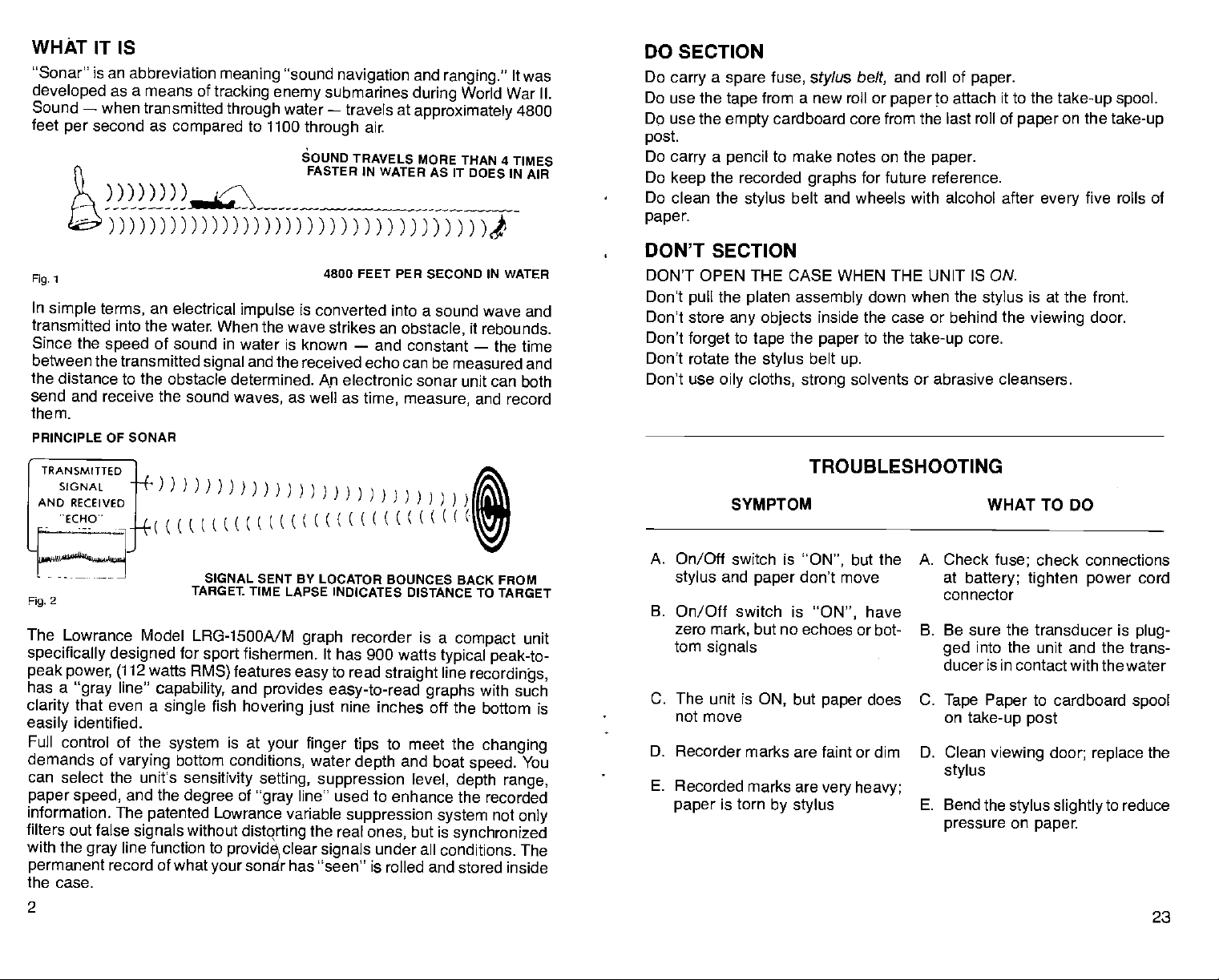
WHAT IT IS
'Sonar" is an abbreviation
developed
Sound
feet
as a means of
—
when transmitted
second as
per
meaning
tracking
through
compared
_____
enemy
to 1100
)DD)flflDflflDflflflfl)
1
Fig,
In
simple
transmitted into the water. When the
Since the
between the transmitted
the
send and receive the
them.
PRINCIPLE OF SONAR
terms,
distance to the obstacle determined.
speed
an electrical
impulse
of sound in water is known
and the
signal
sound
waves,
"sound
water
navigation
submarines
—
travels at
through
SOUND TRAVELS
FASTER
air.
IN WATER
and
ranging."
World War II.
during
approximately
MORE THAN 4
AS IT DOES IN AIR
)fl)flfll
4800 FEET PER
is
converted into a sound
wave strikes an
received echo can be measured and
as
—
and constant
electronic sonar unit can both
Ap
well as
time, measure,
SECOND
obstacle,
IN
WATER
wave and
it
rebounds.
—
the time
and
record
It was
4800
TIMES
DO
SECTION
Do
Do use the
Do use the
post.
Do
Do
Do clean the
paper.
a
carry
carry a pencil
keep
spare
tape
empty
the recorded
stylus
fuse,
from a new roll or
cardboard core from the last roll of
to make notes on the
DON'T SECTION
DON'T
Don't
Don't
Don't
OPEN
pull
store
forget
Don't rotate the
Don't use
THE
the
platen assembly
any objects
to
tape
stylus
cloths,
oily
stylus
paper
paper.
to attach it to the
and roll of
belt,
paper
paper.
graphs
for future reference.
belt and wheels with alcohol after
inside
the
paper
belt
strong
WHEN THE UNIT IS ON.
down when the
the
to the
up.
solvents or abrasive cleansers.
or behind the
case
take-up
stylus
core.
CASE
take-up spool.
on the
take-up
five rolls of
every
is at the front.
viewing
door.
TRANSMITTED
GNAL
AND RECEIVED
'ECHO"
- ---—-
2
Fig,
The
Lowrance Model LRG-1500A/M
specifically designed
peak power, (112
has a
"gray
that
clarity
identified.
easily
Full control
demands of
can select the unit's
paper speed,
information. The
filters out false
With the
permanent
1
I
L((((((((((w
watts
line"
even a
of the
varying
and the
patented
signals
line function to
gray
record of what
SIGNAL
TARGEt
for
sport
RMS)
capability,
single
system
bottom
sensitivity
degree
fish
without
your
( (
K K
((K
SENT BY LOCATOR BOUNCES BACK
TIME LAPSE INDICATES DISTANCE
fishermen. It
features
and
hovering just
is at
conditions,
graph
easy
provides easy-to-read
your finger tips
recorder is a
has 900 Watts
to
read
nine
inches off the bottom is
water
depth
straight
to meet
selling, suppression level, depth
of
Lowrance
distqrting
provide)clear
sonar
line" used to enhance the
"gray
Variable
has 'seen" is rolled and stored
suppression system
the real
signals
ones,
under all conditions.
compact
typical peak-to-
line
graphs
the
and boat
but is
synchronized
FROM
TO TARGET
unit
recordin'gs,
with such
changing
speed.
You
range,
recorded
not
only
The
inside
SYMPTOM WHAT TO
A. On/Off switch is
and
stylus
B.
On/Off switch is
zero
tom
C. The unit is
mark,
signals
paper
but no echoes or bot-
ON,
not move
D. Recorder marks are faint or dim D.
E.
Recorded marks are
is torn
paper
TROUBLESHOOTING
"ON",
don't move
but
by stylus
but the
paper
have
does
"ON",
very heavy;
DO
A.
Check
at
battery; tighten power
connector
check connections
fuse;
B. Be sure the transducer is
into the unit and
ged
ducer is in contact with the water
C.
Tape Paper
on
take-up post
Clean
stylus
E. Bend the
pressure
to cardboard
viewing door;
stylus
on
paper.
replace
slightly
the trans-
to reduce
cord
plug-
spool
the
the case.
2
23
PDF compression, OCR, web-optimization with CVISION's PdfCompressor
MAINTENANCE
NOTE:
platen
the
to remove
Black carbon
oil-free
pressure
from
After
should be
carbon dust.
All mechanical
haven't worked
DO NOT
DO NOT wash
remove
HIGH VOLTAGE
attempt
Corrosion
splices,
The
stylus may
assembly
when
platen
changing
stylus.
dust is created
to clean the
rag
compressed
moving parts
five rolls of
every
wiped
Strong
connections should
loose.
any type
apply
the unit with
salt
accumulations,
should be made
electronic section.
occur
may
or at the
checked
periodically
The face of the transducer,
periodicallywith
film. This is
oily
essential to have
be
pulled
down.
is
the
viewing
air
may
if the air is
paper,
clean with a soft
solvents
of lubricant
is
present
by any
at the
battery
mild
connections.
and cleaned as
soapywaterto
the water.
Periodically,
cloth
dampened
page
the rubber roller
with
16, Figure 29).
alcohol,
in front of the
damaged
paper
if it is
Always
during
move
rolls. Remember
the
recording process.
door and metal
be used to blow dust
and free of oil.
dry
stylus
moistened
rag
belt and
the
or abrasive cleaners
be checked
to the motors or
running
dust,
in the
power plug,
if mounted
on the
to
water.
Wiping
road
or
transmitter section when
unauthorized
grime
in the fuse
All electrical connections
necessary
on the transom
remove
good
paper
improve
any
contact between
drive should
the friction
the
stylus
platen
to the back
to move the
Use a
behind the
platen
out of the case and
the wheels it rides
with alcohol to remove
should not be used.
gear
with a
that's
to be sure
trains.
damp
necessary.
periodically
it
is all
the unit is ON.
person
to
holder or
400
with
accumulated
modify
or
grit sandpaper.
should be washed
road
the transducer and
be cleaned with
on the drive shaft.
when the
side of
belt down
soft,
Low
paper.
away
they
cloth to
repair
cord
power
should be
grime
(See
on
No
the
or
a
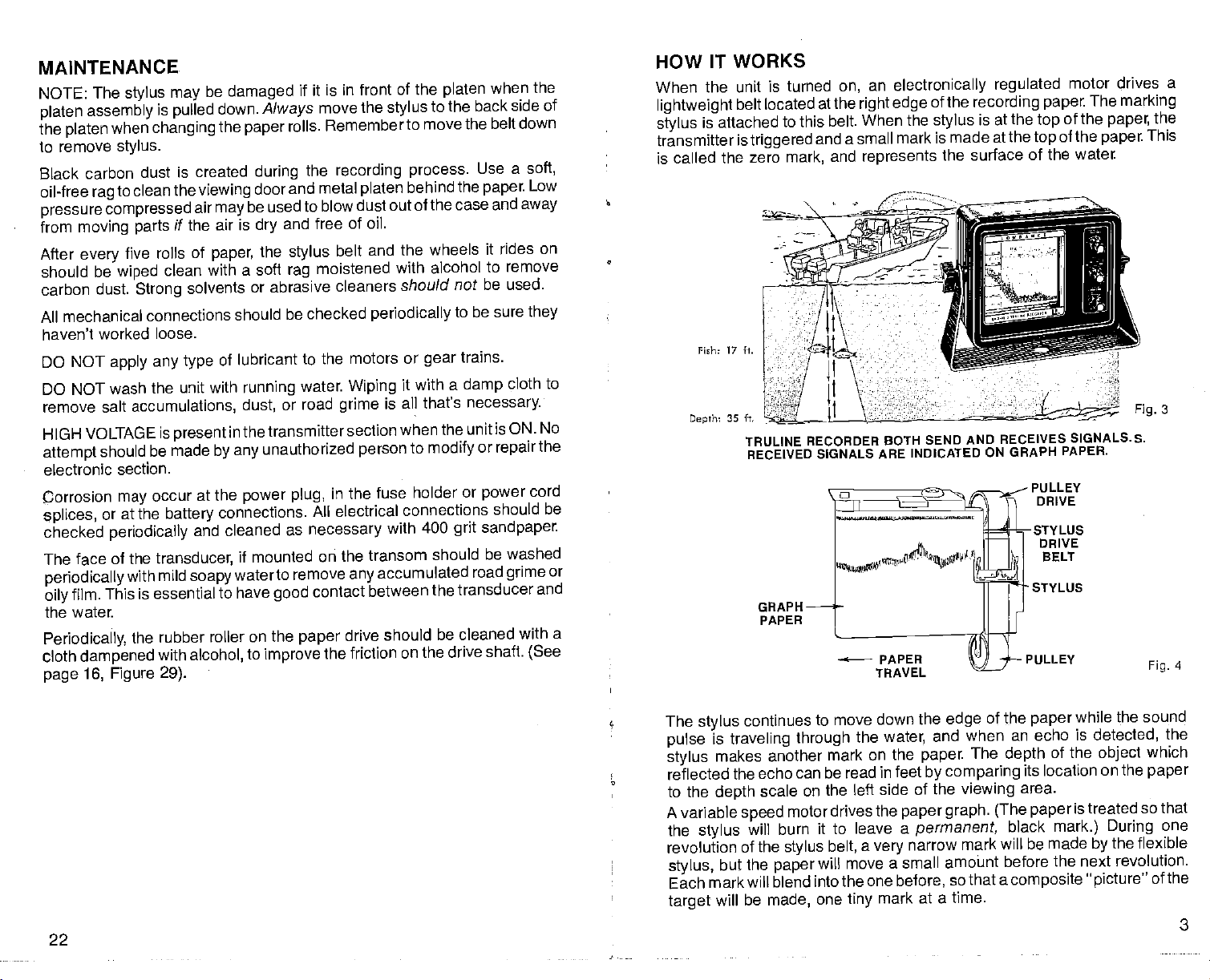
HOW IT WORKS
When the unit
lightweight
is attached
stylus
transmitter is
is called the zero mark,
Fish: 17 ft.
eprh:
is turned
located atthe
belt
to this belt. When the
triggered
35 ft.
TRULINE RECORDER BOTH
RECEIVED SIGNALS ARE
GRAPH
PAPER
an
on,
right edge
and a small
and
represents
electronically regulated
of the
recording
is at the
stylus
mark is made at
the surface of
SEND AND RECEIVES
INDICATED ON GRAPH
paper.
top
thetop
the water.
PULLEY
DRIVE
-STYLUS
DRIVE
BELT
STYLUS
LLEY
motor
The
of the
paper,
of the
paper
SIGNALS. 5.
PAPER.
drives a
marking
the
This
3
Fig.
Fig.
4
The
pulse
stylus
reflected the echo can
to the
A variable
the
revolution of
stylus,
Each mark will
target
continues to
stylus
is
traveling through
makes another
scale
depth
speed
stylus
will burn
the
the
but
paper
blend into the one before,
will be made,
on the left side of
motor drives the
stylus
move down the
the
water,
mark on the
be read in feet
it to leave a
a
belt,
very
will move
one
a small amoiint before
mark
tiny
of the
edge
when an echo is
and
The
paper.
by comparing
the
viewing
graph. (The paper
paper
permanent,
narrow mark will be made
paper
of the
depth
its location on
area.
black
mark.)
the next revolution.
so that a
composite
at a time.
the sound
while
detected,
object
the
is treated
During
the flexible
by
picture"
the
which
paper
so that
one
of the
3
22
PDF compression, OCR, web-optimization with CVISION's PdfCompressor
 Loading...