

Lowrance LRA5000, LRA3000, LRA4000, LRA2000, LRA1500 User Manual
...
www.lowrance.com
Pub. 988-0161-011
Radar Operation
Instruction Manual

Copyright © 2006 Lowrance Electronics, Inc.
All rights reserved.
No part of this manual may be copied, reproduced, republished, transmitted or distributed for any purpose, without prior written consent of
Lowrance Electronics. Any unauthorized commercial distribution
of this manual is strictly prohibited.
Lowrance
NMEA 2000
is a registered trademark of Lowrance Electronics, Inc.
is a registered trademark of the National Marine Elec-
tronics Association.
Lowrance Electronics may find it necessary to change or end our policies,
regulations and special offers at any time. We reserve the right to do so
without notice. All features and specifications subject to change without
notice. This manual covers all display units compatible with Lowrance
Radar at press time. On the cover: LCX-111c HD sonar/GPS unit.
For free owner's manuals and the most current information on
this product, its operation and accessories,
visit our web site:
www.lowrance.com
Lowrance Electronics Inc.
12000 E. Skelly Dr.
Tulsa, OK USA 74128-2486
Printed in USA.

Table of Contents
Warnings and Cautions .......................................................... iii
Section 1: Introduction............................................................. 1
Models Covered ............................................................................. 1
Update Display Unit Software ..................................................... 2
What is radar? ............................................................................... 2
Basic Radar Display Components ................................................ 4
Section 2: Radar Setup ............................................................. 7
Getting Started.............................................................................. 7
Radar Setup ................................................................................... 9
Trigger Delay Preparation........................................................ 9
Range...................................................................................... 9
Gain ........................................................................................ 9
Anti-Sea Clutter .................................................................... 9
Anti-Rain Clutter ................................................................ 10
Main Bang Suppression ...................................................... 10
Trigger Delay ....................................................................... 10
Adjust Trigger Delay............................................................... 10
Adjust Main Bang Suppression .............................................. 12
Adjust Heading Line ............................................................... 13
Adjust Transmit Off Zone ....................................................... 14
Adjust Tune ............................................................................. 15
Section 3: Basic Operation .................................................... 17
Pages ............................................................................................ 17
Radar Only............................................................................... 17
Radar with Map....................................................................... 17
Radar with Sonar .................................................................... 18
Radar with Gauges.................................................................. 18
Radar Menu ................................................................................. 19
Gain .......................................................................................... 19
Anti-Sea Clutter (STC): .......................................................... 20
Anti Rain Clutter (FTC).......................................................... 20
Interference Rejection ............................................................. 21
Radar Range ............................................................................ 21
Radar Echo Expansion............................................................ 21
Echo Trail Interval .................................................................. 22
Clear Radar Trails................................................................... 22
Adjust Radar PPI Offset ......................................................... 23
Recenter Radar PPI................................................................. 23
Log Radar Data ....................................................................... 24
Record a radar log: .............................................................. 24
Change the file name: ......................................................... 24
i

Browse data files: ................................................................ 24
Copy data files: .................................................................... 25
Delete a data file:................................................................. 26
Stop or play a data file: ....................................................... 26
Rename a data file:.............................................................. 26
Radar Setup ............................................................................. 26
Radar Orientation ................................................................... 27
Radar Color Scheme................................................................ 27
Adjust Antenna Park .............................................................. 27
Radar Information................................................................... 28
Radar Power ............................................................................ 29
Turn radar on or off:............................................................ 29
Radar Simulator ...................................................................... 29
Section 4: Advanced Operation ............................................ 31
Reading the Display .................................................................... 31
Gain .......................................................................................... 31
Range Rings............................................................................. 31
Anti-Sea Clutter (STC) ........................................................... 32
Anti-Rain Clutter (FTC) ......................................................... 32
Electronic Bearing Line (EBL) ............................................... 32
Variable Range Markers......................................................... 32
Select an EBL and VRM: .................................................... 32
Reposition EBL and VRM:.................................................. 34
Remove EBL-VRM from the display: ................................. 35
Section 5: Radar Interpretation........................................... 37
Anti-Rain Clutter (FTC or Fast Time Constant) ...................... 37
Echo Trails................................................................................... 40
Typical Small Boat Targets ........................................................ 42
Shoreline Images ......................................................................... 44
Recommended Reading ............................................................... 46
Appendix I: Glossary............................................................... 47
FCC Compliance ...................................................................... 50
ii

Warnings and Cautions
Caution:
Use this radar at your own risk. This radar was designed for
use as a navigation aid. It should not be used for purposes that
require precise measurements of direction, distance, topography
or location. Always compare the navigation information received
from your radar with data from other navigation aids and
sources. When a conflict arises between the navigation data from
your radar and data from other navigation aids, make sure you
resolve the conflict before proceeding with navigation. A CARE-
FUL NAVIGATOR NEVER RELIES ON ONLY ONE
METHOD TO OBTAIN NAVIGATION INFORMATION.
Caution:
International Regulations for Preventing Collisions at Sea mandate that when radar is on a vessel, the radar must be used at
all times, regardless of weather conditions or visibility. Numerous court decisions have not only ruled the radar must be used,
but that the radar operator must be knowledgeable in all operational aspects of radar performance or otherwise face a greater
risk of liability if an accident occurs.
Caution:
If you purchased an open array radar antenna, make sure it is
installed in an area free of hardware obstructions and free of potential obstructions like sails, lines or other vessel components
that could intermittently intrude or be caught up in the array
antenna's rotation path.
WARNING: High Voltage Hazard
Dangerously high voltages are present within the radar
scanner unit. The unit contains no user-serviceable
parts. The cover should be removed only by a qualified
radar service technician. Technicians must exercise extreme care when working inside the unit. ALWAYS remove power before removing the cover. Some capacitors
may take several minutes to discharge, even after
switching off the radar. Before touching the magnetron
or any high voltage components, ground them with a
clip lead. There are no internal connections or adjustments necessary for installation or operation.
iii

WARNING: Microwave Radiation Hazard
The microwave energy radiated by a radar antenna is
harmful to humans, especially to the eyes. NEVER look
directly into an open waveguide or into the path of radiation from an enclosed antenna. Radar and other radio frequency radiation can upset cardiac pacemakers.
If someone with a cardiac pacemaker suspects abnormal
operation, immediately turn off the radar equipment
and move the person away from the antenna. Turn off
the radar whenever it is necessary to work on the antenna unit or other equipment in the beam of the radar.
WARNING: Turn Off Radar When Docked
The radar beam can be harmful to humans in close proximity (within 20 yards, or 18.3 meters). When docked, be
considerate of other boats and pedestrians nearby and
remember to turn off your radar. If your boat is in a covered marina and the radar is on, a metal roof can act as
a reflector, bouncing microwave energy back at your
boat and passengers.
iv

Section 1: Introduction
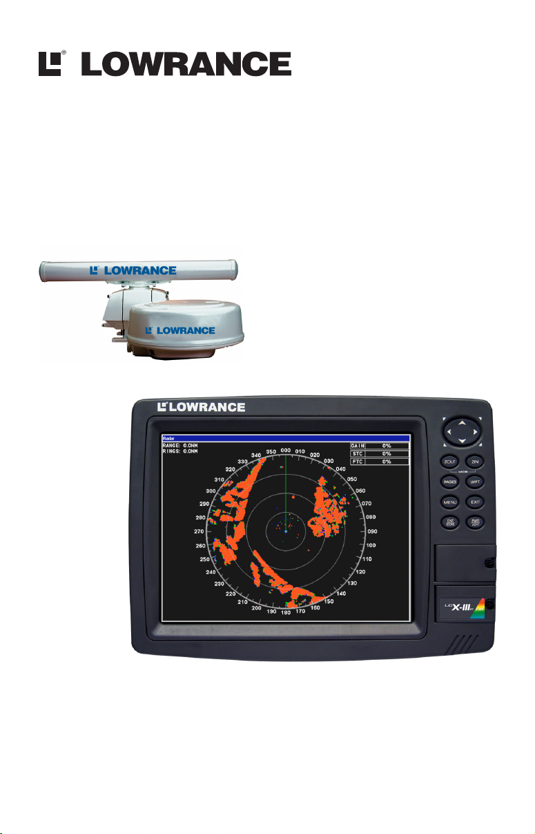
Thank you for buying a Lowrance Radar with the RIM 100 radar interface module. Your radar consists of three main components: the radar
scanner unit (antenna), your display unit (sold separately) and the RIM
100 radar interface module which connects the scanner and display units.
WARNING:
Radar radiation can be harmful to you and bystanders.
Radar misuse or misunderstanding radar operation
could lead to a collision, which could result in property
damage, personal injury or death.
You must be familiar with the procedures and all warnings and cautions described in the installation and operation manuals in order to operate your radar safely
and effectively.
We know you’re eager to begin using your radar, but first, we want you to
take note of the three instruction manuals you need to read to get started.
First is the Read Me! Insert for Radar Display Unit Software Update
(part number 988-0161-022). It tells you how use the memory card in
your package to update your display unit software to make it radarready. (For your convenience, this information is also repeated below.)
Second is the Radar and RIM 100 Installation Manual (part number
988-0161-001). It tells you how to install your radar's hardware.
Third is this Radar Operation Manual (part number 988-0161-011).
After installing the radar scanner unit, the RIM 100 and the new display software, you need to read this manual to learn how your display
unit and radar antenna work together.
To get the highest level of performance from your radar, it is a good
idea to keep this manual and your display unit's sonar or GPS instruction manual handy for reference.
Models Covered
This manual covers the following radar-compatible display units: LCX25c, LCX-26c HD, LCX-110c, LCX-111c HD sonar/GPS combos; and
GlobalMap
Map
Note for GlobalMap users: Menus and function commands in your
units are identical to those shown in this manual, except your display
will not have sonar page options, sonar alarm options or sonar simulator options.
6500c, GlobalMap 6600c HD, GlobalMap 7500c, Global-
7600c HD GPS units.
1

This manual covers the following radar units: LRA-1000, LRA-1500,
LRA-2000 radomes; and LRA-4000, LRA-5000 open array radars.
Update Display Unit Software
Your display unit must have software version 1.3.0 or later to work
with radar. Depending on when you bought your display, it may require
a software update. To avoid delays in setting up your radar system,
your radar package includes an MMC or SD memory card with a basic
software upgrade.
Lowrance continues to regularly develop display enhancements and
new radar features. We strongly recommend that you periodically
check our web site for the latest free radar software updates.
If you or a friend has Internet access, log-on to
browse to our Software page and look for the Product Updates link. If
you lack Internet access, call your dealer or Lowrance Customer Service. Complete contact information is on the last page of this manual.
We've made it easy for you to keep up with our latest updates — just
subscribe to our free e-mail software release notices. Look for the link
at the bottom of our Product Software Upgrades web page.
Installing Software Update
1. With the display unit turned off, install the MMC card that contains
the radar software update.
2. Turn on the unit and the update will install automatically.
3. When the update is finished, the unit will power up normally. After
the updated is complete, remove the update MMC from card slot.
NOTE:
This manual assumes you have a basic understanding of your display
and its sonar and/or GPS operations. For complete instructions on
the keyboard, pages and menu structure, refer to the manual packed
with your display. That manual also explains the typographical conventions and symbols we use to describe unit operations.
www.lowrance.com,
What is radar?
The word "radar" is an acronym for "RAdio Detecting And Ranging." In
simple terms, this is how it works:
A radio transmitter sends out a quick microwave pulse. A receiver listens
for that signal's echo when it bounces back from something in its path.
2

When the echo returns, it is processed by a computer to determine relative distance, position and bearing of the object that reflected the signal. This information is displayed on the display unit's screen. Other
boats or ships, navigational markers, landmasses and the like are referred to as targets.
By knowing how long it takes for a signal to return, the distance to a target can be determined. As the radar antenna scans through a 360 degree
rotation, it can show where the target is relative to your position. By repeated scans, you can see which direction another vessel is moving.
The following two pages show the basic components of your radar display screen, which is commonly referred to as the PPI, an old term from
the early days of radar.
3
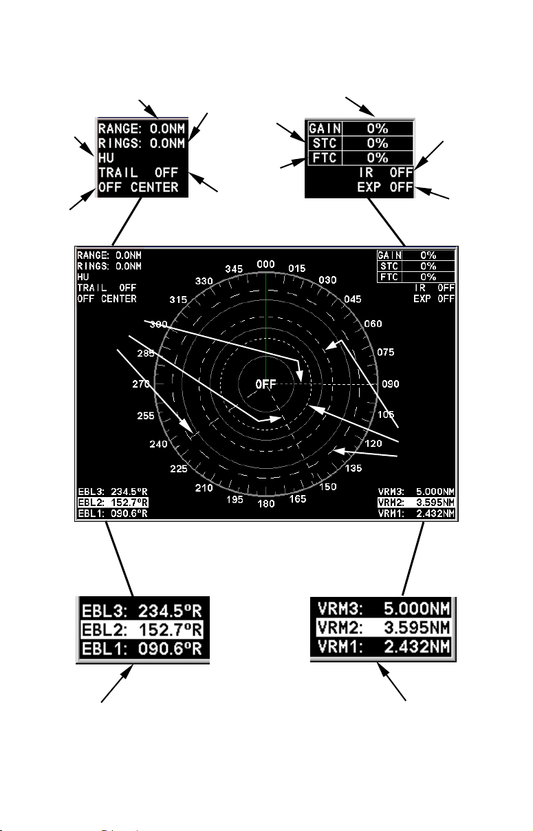
Basic Radar Display Components
A
A
Ga
V
V
Display
mode
PPI Position
status
Electronic
Bearing
Lines
Range
Range Ring
Interval
Clutter
Echo Trail
status
nti-Sea
Clutter
nti-Rain
in level
Interference
Rejection
status
Radar Echo
Expansion
status
ariable
Range
Markers
lines and three variable range markers.
Electronic Bearing Line position
for EBLs 1, 2 and 3. Highlighted
in white, EBL 2 is the active
bearing line.
Your unit has three electronic bearing
An enlarged example of EBLs and
VRMs is on the next page.
ariable Range Marker position
for VRMs 1, 2 and 3. Highlighted
in white, VRM 2 is the active
range marker.
4
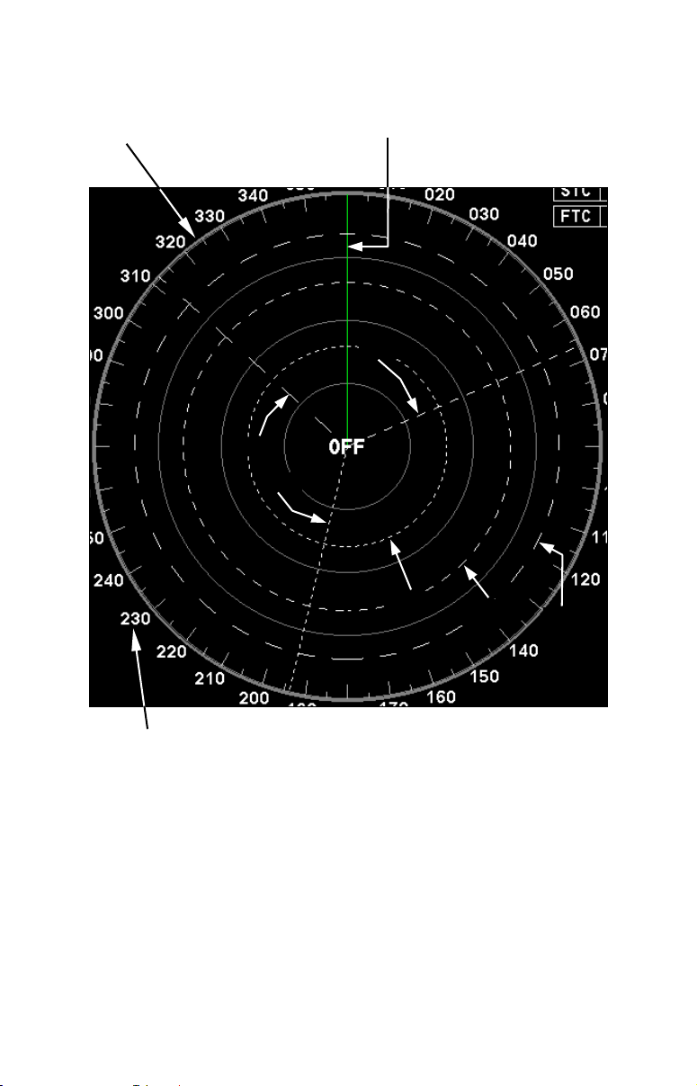
Basic Radar Display Components
PPI (radar screen's 360º
overhead view of the area)
EBL3
EBL1
Heading line (in green)
EBL2
VRM1
VRM2
VRM3
Bearings, in degrees
(in Heading Up mode,
relative to bow)
VRMs and EBLs allow you to track the distance and bearing
of multiple radar targets.
NOTE:
This manual is printed in black and white, but a free color version
(in Acrobat
PDF format) is available for display or download from
the Lowrance web site. The color manual is particularly useful for
understanding Sec. 5, Radar Interpretation.
5

Notes
6
Section 2: Radar Setup
This section will teach you how to prepare your radar for operation. Before you begin radar setup, the radar scanning unit, RIM 100 module
and display unit must all be installed and their cables connected. The
display unit must be running software version 1.3.0 or later.
WARNING:
Do NOT attempt to execute Radar Setup, while the vessel is moving. Some motion from wind and wave action is
acceptable, but these setup instructions are NOT intended for vessels moving across the water.
Caution:
If you are unsure or do not understand the following instructions, it is strongly recommended that an experienced radar
technician handles radar setup and the installation of radar
hardware.
Getting Started
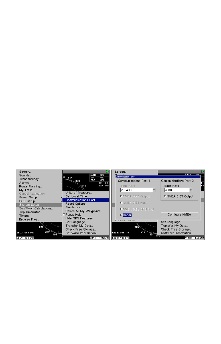
1. After turning on the unit, press MENU|MENU, then use ↑ ↓ to SYSTEM
SETUP and press ENT.
Communications Port selected from System Setup menu (left). Com-
munications Port menu (right).
2. From the System Setup menu, highlight COMMUNICATIONS PORT and
ENT.
press
3. Press ↓ to
checkbox. The Baud Rate automatically will switch to 230400. Press
EXIT repeatedly to return to the main page display.
4. Press
5. Press ↓ to select
RADAR and press ENT, which will place an X in the radar
PAGES, then use ← → to select the radar tab.
RADAR ONLY, then press EXIT.
7
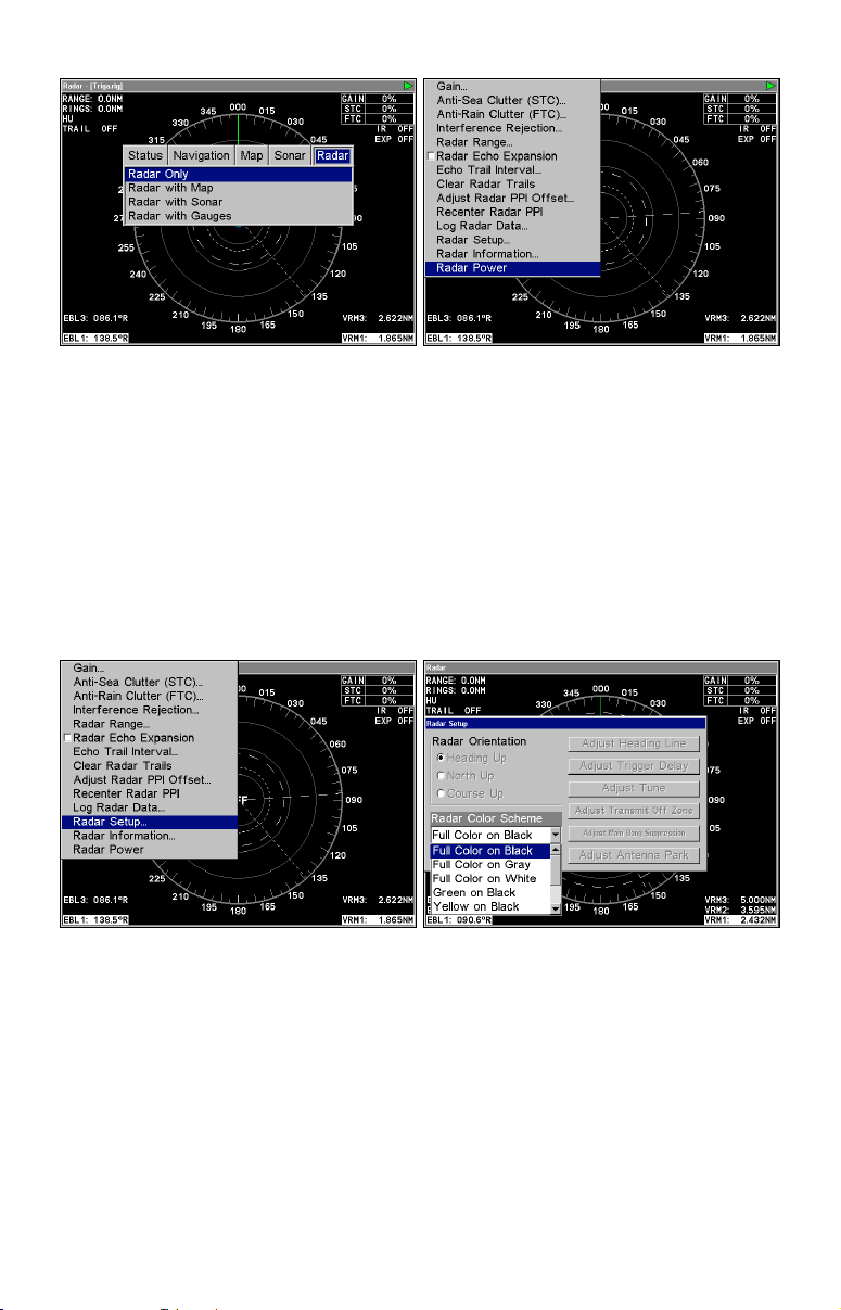
Radar only highlighted on Radar Pages menu (left). Radar menu with
Radar Power selected (right).
6. Press MENU, then use ↑ ↓ to select RADAR POWER from the radar menu
and press
YES and press ENT. A warm-up countdown will commence that will vary
ENT. A confirmation message will appear. Press ← to select
depending on the model of radar you have.
7. After the countdown is finished, the unit will enter STANDBY mode.
8. Access the Radar Setup menu to make sure your radar display is set
to Heading Up and is set to a Full Color scheme. Press MENU, select
RADAR SETUP and press ENT.
Radar Setup selected from Radar menu (left). Radar Setup menu with
Full Color on Black highlighted (right).
9. Highlight HEADING UP and press ENT, which will set the radar to
Heading Up.
10. To display the radar images in full color, press ↓ to select
COLOR SCHEME and press ENT.
RADAR
11. Use ↑ ↓ to highlight one of the three full color options and press
ENT. Press EXIT to return to the main page display.
8

Radar Setup
The Radar Setup menu allows you to setup and adjust radar settings,
like Transmit Off Zone and Antenna Park. Most of the settings in the
Radar Setup menu will only have to be set once, but we recommend you
check the settings periodically for general maintenance.
NOTE:
Before starting radar setup, take your vessel out on open water
with fairly calm seas, like an open bay.
The three setup features we want to modify are Adjust Trigger Delay,
Adjust Main Bang Suppression and Adjust Heading Line.
We will set them up in that order, but before making any adjustments,
make sure the display is set to a range of 1/8 nautical miles and that
Gain, Anti-Sea Clutter (STC), Anti-Rain Clutter (FTC), Main Bang
Suppression and Trigger Delay all have been set to zero percent.
Trigger Delay Preparation
Range
1. To reset range to 1/8 nm, make sure you are on the Radar Only page
and press
MENU.
2. Use ↑ ↓ to select
Radar Range list. Press ↑ to select 1/8 nm and press
set the range to 1/8 nm from the radar screen by using the
ZOUT keys.
Gain
RADAR RAN GE and press ENT, which will call up the
ENT. You also can
ZIN and
1. To set Gain to zero, press MENU, select GAIN and press ENT.
2. That will launch the Gain vertical scrollbar. Press ↓ until the Gain is
set to zero percent. Press
EXIT. (Notice the corresponding value in the
upper right-hand corner of the screen.)
NOTE:
When adjusting Gain back to a useable level, increase the level until you see a light peppering on the display. Also remember, you will
have to adjust gain every time you change ranges.
Anti-Sea Clutter
1. To set Anti-Sea Clutter to zero, press MENU, select ANTI-SEA CLUTTER
(STC) and press ENT.
2. That will launch the Anti-Sea Clutter vertical scrollbar. Press ↓ until
the Anti-Sea Clutter is set to zero percent. Press
EXIT. (Notice the cor-
responding value in the upper right-hand corner of the screen.)
9

Anti-Rain Clutter
1. To set Anti-Rain Clutter to zero, press MENU, select ANTI-RAIN CLUTTER
(FTC) and press ENT.
2. That will launch the Anti-Rain Clutter vertical scrollbar. Press ↓ until the Anti-Rain Clutter is set to zero percent. Press
EXIT. (Notice the
corresponding value in the upper right-hand corner of the screen.)
Main Bang Suppression
1. To set Main Bang Suppression to zero, press MENU, select RADAR
SETUP and press ENT.
2. Press →|↓ to
ADJUST MAIN BANG SUPPRESSION and press ENT. That will
call up the Main Bang Suppression vertical scrollbar.
3. Press ↓ until Main Bang Suppression is set to zero percent. Press
EXIT.
Trigger Delay
1. To set Trigger Delay to zero, press MENU, select RADAR SETUP and
ENT.
press
2. Press →|↓ to
ADJUST TRIGGER DELAY and press ENT. That will call up
the Adjust Trigger Delay vertical scrollbar.
3. Press ↓ until Trigger Delay is set to zero percent. Press
EXIT.
Adjust Trigger Delay
This feature eliminates the time lag between real radar returns and the
time it takes data to be processed by the radar software, a common issue with all radars.
Caution:
If you have any doubt about your understanding of the Trigger
Delay feature, you should have it set up by a qualified radar
technician.
1. The radar should already be in STANDBY mode, so press
PWR for 2
seconds to switch the radar into transmission mode. A confirmation
message will appear, press ← to select
YES.
2. Press
MENU, then select GAIN and press ENT, which will call up the
Gain vertical control bar. Press ↑ to increase the Gain level to around
15%. One or two red rings with blue borders should be visible on the
screen, depending on the wattage of your radar antenna.
3. Now from the Radar Setup menu, press →|↓ to
then press
ENT. The Adjust Trigger Delay vertical scrollbar will appear.
ADJUST TRIGGER DELAY,
10
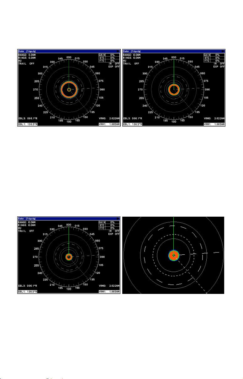
The 2 kW models, the LRA-1000 and LRA-1500, will have only one ring
on the display. The 4 kW radars — LRA-2000, LRA-4000 and LRA-5000
— will have two rings on the display. See the following figures.
Before adjusting the Trigger Delay for 4 kW radars, two rings will be
shown on the screen (left). As Trigger Delay is increased, the larger
ring will start to get smaller. The small ring will disappear (right).
You may have to increase gain in the previous step if the rings are not
visible. Increase gain until you have solid red rings shown on the
screen, like in the preceding example. Increasing Gain too much can
cause distortion of the rings.
4. Press ↑ to increase the level of Trigger Delay, which will decrease the
size of the ring. If you have a 4 kW radar, as the large ring decreases in
size, the smaller ring in the center of the screen will disappear, leaving
only one ring.
Increase Trigger Delay to diminish the size of the red ring (left). To set
Trigger Delay correctly, reduce the ring to as small a size as possible,
while keeping a black circle in the middle (enlarged view, right).
In either case, continue to increase the Trigger Delay level until the
ring is as small as possible, while keeping a black circle in the middle.
Every radar is different, but typically, a setting between 35 and 42 percent will get the job done.
11

If you over apply the Trigger Delay, the black circle will disappear. Decrease the Trigger Delay level and it will reappear.
3. Press
EXIT to return to the main page display.
Adjust Main Bang Suppression
Main Bang Suppression is only for 4kW units —
LRA 5000. This feature filters out electronic noise close to your vessel. It
LRA 2000, LRA 4000 and
gives you control of radar sensitivity in the area surrounding your vessel, approximately 180 feet in all directions.
Before making any adjustments to Main Bang Suppression, take your
vessel out on open water with fairly calm seas, like an open bay.
Caution:
If you have any doubt about your understanding of the Main
Bang Suppression feature, you should have it set up by a qualified radar technician.
1. From the Radar Setup menu, press →|↓ to
PRESSION
and press ENT. That will launch the Main Bang Suppression
ADJUST MAIN BANG SUP-
vertical scrollbar.
2. The small red ring we adjusted during Trigger Delay setup will still
be on the display.
3. Press ↑ slowly — Main Bang Suppression can be sensitive — to increase the Main Bang Suppression level so the red ring becomes as thin
as possible.
4. Press ↓ to slowly decrease the level until you have returned the red
ring back to its thinnest point. Every radar is different, but typically, a
setting between 2 and 8 percent will be satisfactory.
NOTE:
In many cases, depending on the radar unit you have, over applying
Main Bang Suppression can make the ring disappear, start to make
it wider or the ring can get to a point where it is as small as it will
get. At this point, increasing the main bang level will not change
the red ring.
If the red ring does not does not decrease in size when increasing
the suppression level, reduce the level until you see a slight increase in the size of the ring, then leave it at that setting.
12
 Loading...