

Lowrance LRA2400 HDS, LRA1800 HDS User Manual
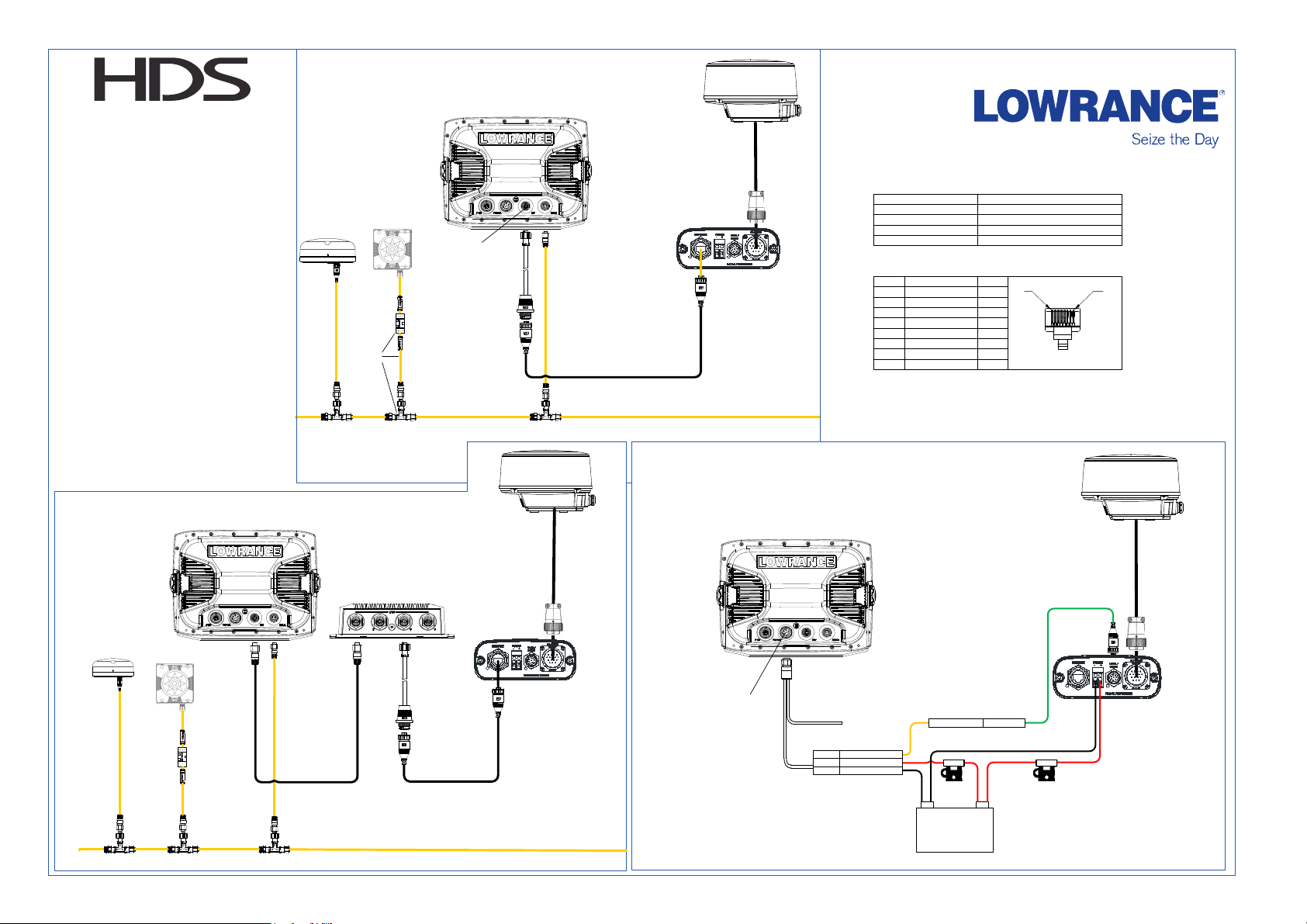
LRA 1800 & LRA2400
Radar Installation Guide
Radar connected directly to HDS display
A
LA000610A-G
B
A = Lowrance HDS display
B = LRA1800 or LRA2400 scanner
C = Radar processor
D = Adapter cable 000-0127-56 to
RJ45
E = Ethernet cable RJ45 **
F = GPS antenna
G = Heading Sensor for chart
overlay
H = SimNet adapter kit
I = NEP-1
J = Ethernet cable (Lowrance)
K = 12 Pin utility cable
(AA010070)
Radar connected via NEP-1
FG
H
I
ENET
D
C
E
NMEA 2000 Backbone
Power connection using optional
“Accessory Wake Up” to turn on
radar when HDS is on.
Available RJ45 Ethernet cables lengths
* *
AA010079
AA010080
AA010081
AA010082
AA010085
Ethernet cable pinout
PIN Wire Color
1 Green / White
2 Green
3 Orange / White
4 Blue
5 Blue / White
6 Orange
7 Brown / White
8 Brown
POWER CONNECTION
0.5 meter (1.6') Ethernet cable
2 meter (6.6') Ethernet cable
5 meter (16.5') Ethernet cable
10 meter (33') Ethernet cable
Ethernet RJ45 Field Termination Kit
Func.
TX+
TXRX+
N/C
N/C
RXN/C
N/C
P1P8
K
D
PWR-DATA
Yellow Accessory wake-up
Red
J
E
Black
Display Pwr +
Display Pwr -
-
NMEA 2000 Backbone
12 V DC
Light GreenRemote Pwr On
+
 Loading...