

Page 1
LMS-1
50
LITHO
IN
U.S.A.
988-0119-28
c.
I®LQWRAfjcE
INSTALLATION
INSTRUCTIONS
1?000 E.
SKELLY
AND
OPERATION
ELECTRONICS,
DR.,
TULSA,
OK
INC.
74128
PDF compression, OCR, web-optimization with CVISION's PdfCompressor
Page 2
NOTES:
Copyright© 1991,1992,
All
All sonar and loran
Features and
specifications subject
This loran receiver
will show the
shortest,
provides navigation
obstructions.
take
only
will also
to a
path
Therefore,
advantage
visually
waypoint
screens
(like
data
of all available
check to make dertain a
is
always
USE THIS LORAN RECEIVER ONLY AS
NAVIGATION. A CAREFUL NAVIGATOR NEVER
Lowrance
reserved.
rights
in
this manual are simulated.
to
CAUTION
all loran
navigation
most direct
the
to
the
WARNING!
waypoint, regardless
prudent navigator
available.
Electronics,
change
path
without
to a
navigation
clear,
equipment)
waypoint.
AN AID
RELIES ON ONLY ONE METHOD TO OBTAIN
POSITION INFORMATION.
Inc.
notipe.
It
of
will not
tools,.but
safe
TO
NOTICE!
MAKE CERTAIN THE LORAN IS DISPLAYING THE CORRECT
POSITION IN LATITUDE/LONGITUDE COORDINATES BEFORE
NAVIGATING WITH
RECT
ERLY.
FOR THE NAVIGATION FEATURES TO WORK PROP-
THIS UNIT. THE POSITION MUST BE COR-
PDF compression, OCR, web-optimization with CVISION's PdfCompressor
Page 3
NOTES.
INTRODUCTION
MOUNTING
POWER
LORAN
SPEED/TEMPERATURE
TRANSDUCER
KEYBOARD
DISPLAY
MEMORY-PRESET
FREQUENCYSELECT
AUTOMATIC
SENSITIVITY
GRA'YUNBE
RANGE
ZOOM-Automauc
SONAR
SONAR
CHARTSFEED
FISH I.D
CHART
SONAR
CONNECTIONS
MODULE
-
Automauc
Manual
Manual
MENUS
MENU-PAGEI
CURSOR
ALARMS
DEPTHALARMS
SHALLOW
DEEP
ZONEALARM
FISH
ALARM
ALARM
AUDIO ALARM
SONAR MENU
CONSTRUCT
SELECT
FASTRAK
ASP
SONAR
NOISE
SET
DISPLAY
DISPLAY
SONAR MENU
-
PAGE 2
DIGITAL
-
MENU
PAGE
REJECTION
SURFACE
ZONE ALARM
ZOOM
L
PAGE 4
DIGITAL
DGITALSONAR
DIG!TAL
SONARMENU
SONAR
-PAGE 5
INSTALLATION
SENSOR
CONNECTIONS
ALARM
ON/OFF
BLOCK
SIZES
CLARITY
(5CC)
BAR
WINDOW BAR
FREQUENCY
TABLE OF
INSTALLATION
CONTENTS
1
.2
2
4
5
6
7
8
9
10
10
12
is
13
15
16
17
18
16
19
20
21
21
21
22
23
24
24
25
27
28
29
so
SI
32
32
SONAR
KEELOFFSET
CALIBRATESPEED
CLEARDISTANCELOG
TURN
SONAR
MENU
SELECT UNITS
DISPLAY
BA)TERY
BACKUP
-
E'AGE
OF
MEASURE
CONTRAST
OFF
SPEAKER VOLUME
BACKLIGHTS
SONAR
TRANSDUCERS
MENU-PAGE
SUSPEND
PRESET SONAR
SONAR
AND
7
OPERATION
AND LORAN
CONE ANGLES
FISHARCHES
SONAR
PDF compression, OCR, web-optimization with CVISION's PdfCompressor
LORAN
TROUBLESHOOTING
OPERATION
as
as
36
36
37
37
37
as
39
41
Page 4

NOTES:
PDF compression, OCR, web-optimization with CVISION's PdfCompressor
Page 5
NOTES;
INTRODUCTION
The LMS-150
today.
perfo'mance.
tion at the
underwater
displays
(distance.
ceiver,
complete
represents
It
rivals, other
With its
touch of a buffon.
world with
boat
speed,
The
log).
with
one of the best
sonar units
menus,
the
The
resolution and
high
surface
loran module
plotter
water
and
values in
much
costing
[MS-iso
CLEARVISIONTM
temperature,
gives
you
waypoint navigation
more in features and
offers
detail. The '[MS-i 50
and
a full
sportlishing
easy-to-use opera-
screen shows the
sonar
also
distance travelled
featured loran re-
capabilities.
Although
menu
different
ing
the [MS-i 50
system
features and
buff
ons!
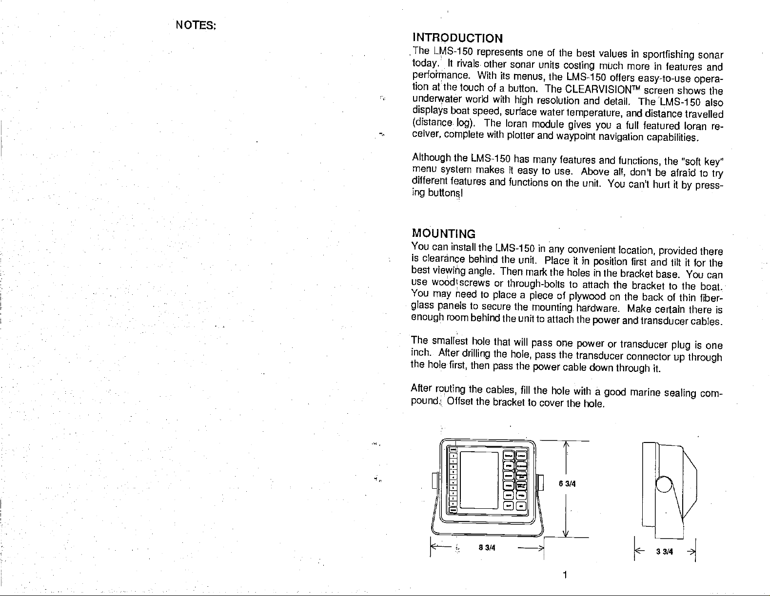
MOUNTING
You
can install
is
clearance behind
best
viewiitig
use
woàthscrews or
You
may
glass panels
enough
The smallest
inch.
the
hole
After
royting
pound.
heed to
room
After
first,
Offset
angle.
drilling
the
has
makes it
easy
functions on the
the LMS-150 in
the unit.
Then mark
through-bolts
place a piece
to
secure the
behind the unit
hole that will
the
hole,
then
pass
cables,
the
fill the
the bracket to
features and
many
to use.
convenient
any
Place it in
the
holes in the
to
of
plywood
mounting,
to attach the
one
pass
the
pass
power
cover the
transducer connector
cable
hole with a
Above
all,
unit. You
position
attach the
on the back
hardware.
power
power
or
down
good
hole.
functions,
don't be
can't hurt ft
location, provided there
first and
bracket base. You
bracket to the
the
'soft
key"
afraid to
by press-
tilt it br Ihe
boat.
try
can
of thin fiber-
Make certain there is
and
transducer
transducer
plug
cables.
is one
up through
through
it.
marine
sealing
cam-
1 PDF compression, OCR, web-optimization with CVISION's PdfCompressor
Page 6
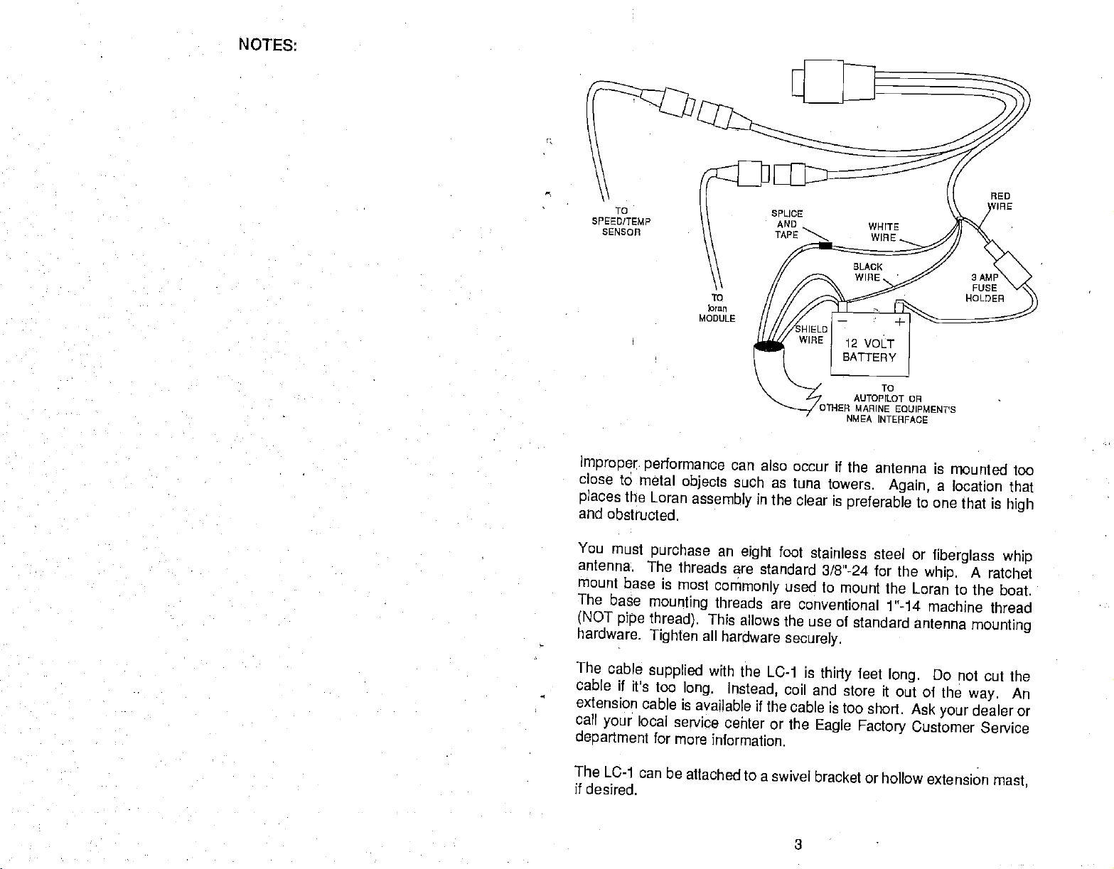
POWER
CONNECTIONS
The LMS-i 5aworks from
results,
power
problems
attach
enough., splice
red
have
end
protect
attach
the
power
cableto an
accessory
with electrical
#18
cable
gauge
the.power
lead as close to the
to extend the
of the fuse
power
holder
both the unit and
interference.
directly
power
directly
a twelve-von
cable
directly
or
battery
to the
power buss,
Therefore,
to
the.battery
wire onto it. Attach
source as
cable to the
the
power
battery
to the
battery
cable in the event of
Far
system only.
battery.
You
however
it's saferto
If
the cable is nS
the best
can attach the
you may
ahead and
go
the in-line fuse holderto the
possible..
For
or
power buss;
or
power
example,
attach one
buss: This will
a short.
have
long
if
you
NOTES:
The
powercable has
lead, black is
interface. To
autopilot
the [MS-i
shield wire
connect the
more
instructions. If
white wire
negative
use this
or
other marine
50's
power
to the black wire
shield wire to the
to
prevent
The [MS-i 50 has
unit if the
until the
Minimize
possible
generators
power
wiring
and
Attach the
150's
power
speed/temperature
wires are hooked
power
is
electrical noise
sources of electrical
is
the
transducer cables
speed/temp
cable.
three
wires, red, white, and
or
ground.
feature,
equipment's
cable. Solder
The white wire is used for
attach a
shielded,
NMEA interfaceto
the twisted
on the LMS-i 50's
autopilot.
you're
not
going
to use this
a short.
reverse
connected
engine's wiring harness.
polarity protection.
backwards.
up
properly.
by
routing
away
sensor's
on the cables
Tags
sensor's connector.
the
interference. One of the
from
and loran module's
black.
twisted
pairs ground
power
See
your autopilot's
feature,
No
damagewill
However,
cable
power
For. best
the
engine wiring.
identify
both the
Red is the
positive
the NMEA
paircable
the white wire on
cable. Do not
cut
fromthe
wire and
manual for
ancitape
dccurto
the
the
it won't work
from
away
largest
results, keep
cable to the [MS-
loran and the
other
noise
the
INSTALLATION
When
where
A
choosing a mounting location,
it's clear of other
location is
high
tenna shouldn't be the
mounted
radio antennas.
vertically.
-
LC-1
Loran-C
antennas, wires, masts,
preferred,
highest part
MODULE
however
of the boat. The
Make certain it is as far
remember to install
the
or other obstructions.
forlightning protection,
antennashould be
away
as
possible
from VHF
E[C-1
the an-
2
PDF compression, OCR, web-optimization with CVISION's PdfCompressor
Page 7
NOTES:
To
SPEED/TEMP
SENSOR
TO
bran
MODULE
Improper. performance can also
close to metal
places
and
You
antenna:.
mount
The
(NOT
hardware.
the
Loran
obstructed.
must
purchase
The threads
is
base
base
mounting
pipe
thread).
Tighten
objects
most
such as
assembly
in the
an
eight
are standard
commonly
threads are
This allows the
all
hardware
AUTOPILOT DR
OTHER
MARINE
NMEA
INTERFACE
occur if the
antenna is
tuna towers.
clear is
foot
preferable
stainless steel
3/8-24 for the
used
to mount the
conventional 1"-14
use of
securely.
standard antenna
IRE
TO
EOUIPMENPS
mounted too
Again, a location that
to one
or
Loran to the
that is
fiberglass
whip.
A
high
whip
ratchet
boat.
machine thread
mounting
The
cable
cable if its
extension cable is
call
your
department
The
LC-1 can
if
desired.
supplied
too
local
for
PDF compression, OCR, web-optimization with CVISION's PdfCompressor
with the LC-1
long.
Instead,
available if
service center
more
information.
be
attached to a
is
thirty
coil and
the cable is
or the
swivel
Eagle
bracket or hollow
3
feet
long.
store h out of
too short.
Factory
Ask
Customer
extension
Do
not cut the
the
way.
dealer or
your
An
Service
mast,
Page 8
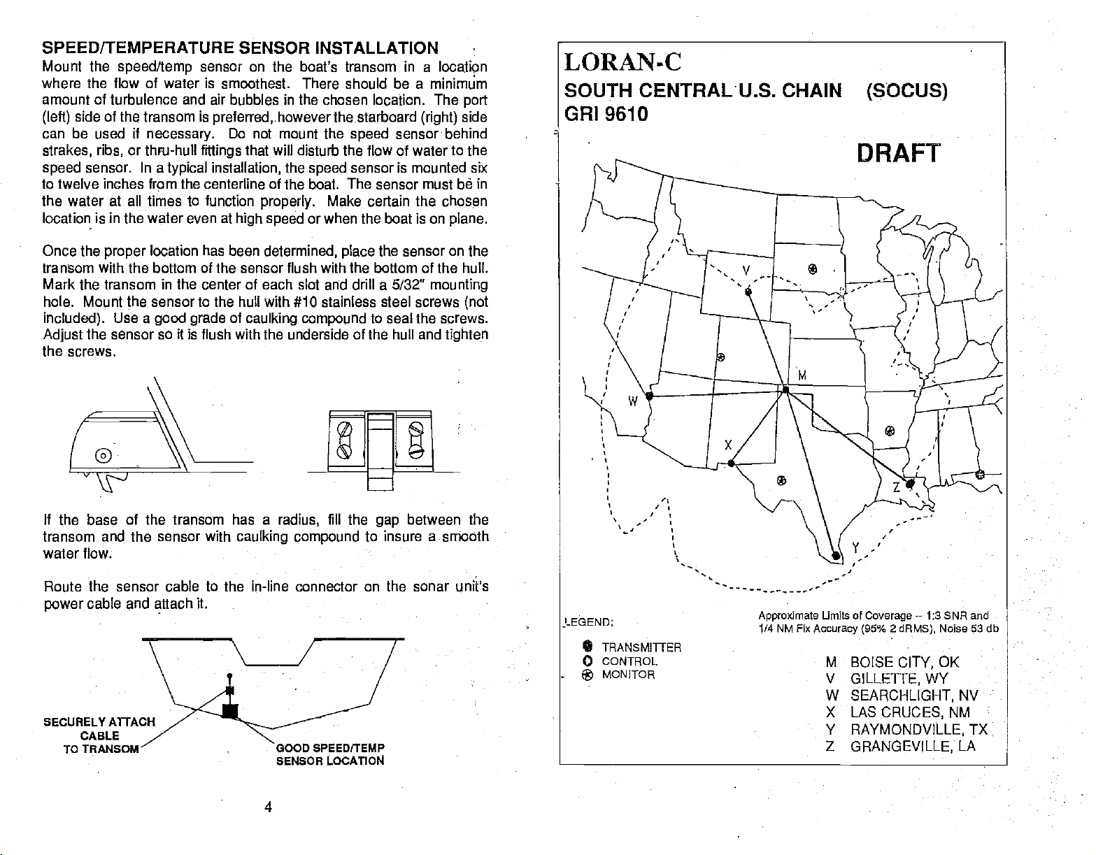
SPEED/TEMPERATURE
Mount the
where the flow of water is smoothest. There should
amount of turbulence and air bubbles in the chosen location. The
side of the transom is
(left)
can be used if
strakes, ribs,
speed
speed/temp
necessary.
or thru-hull
sensor. In a
typical
SENSOR INSTALLATION
sensor on
preferred,.however
Do not mount the
fittings
installation,
the boat's transom in a locatien
thestarboard
that will disturb the flow of water to the
the
speed
minimum
be a
port
side
(right)
speed
sensorbehind
sensor is mounted six
to twelve inches frpm the centerline of the boat. The sensor must be in
the water
location is
at
all times to function
in
the water even at
properly.
high speed
Make certain the chosen
or when the boat is on
plane.
LORAN-C
SOUTH CENTRAL U.S. CHAIN
GRI 9610
(SOCUS)
DRAFT
Once the
proper
location has bean
determined, place
sensor on the
the
transom withthe bottom of the sensor flush with the bottom of the hull.
Mark the transom in the center of each slot and drill a 5/32"
to
hole. Mount the sensor
Use a
included).
Adjust
the sensor so it is flush with the underside of the hull and
good
grade
hull
the
with #10 stainless steel screws
of
caulking compound
to seal the screws.
mounting
(not
tighten
the screws.
It the base of the transom has a
transom and the sensor with
radius,
caulking compound
water flow.
Route the sensor cable to the in-line connector on the sonar unit's
power
cable and attach it.
SENSOR LOCATION
fill the
gap
to insure a smooth
between the
LEGEND:
• TRANSMITrER
o CONTROL
MONITOR
®
Approximate
1/4 NM Fix
Umits of
Accuraoy (95% 2 dRMS),
Coverage--
M BOISE
V
GILLETTE,WY
W
SEARCHLIGHT,
X LAS
Y
Z
CRUCES,
RAYMONDVILLE,
GRANGEVILLE,
1:3 SNR and
CITY,
Noise 53 db
OK
NV
NM
TX
LA
4
PDF compression, OCR, web-optimization with CVISION's PdfCompressor
Page 9
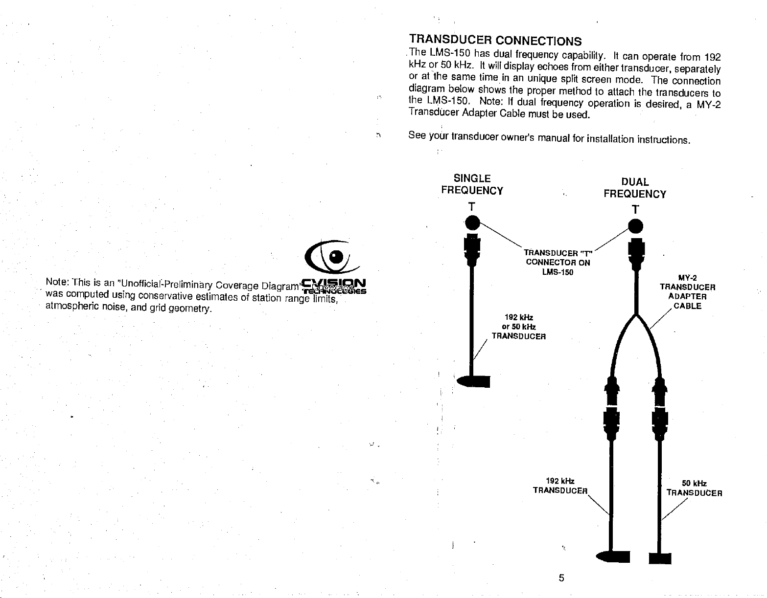
TRANSDUCER
The
LMS-150 has
kHz or
or at
diagram
the
Transducer
50 kHz. It
the same
below
LMS-15o. Note: If
time in an
shows
Adapter
CONNECTIONS
dual
frequency capability.
will
display
Cable must
echoes from
unique split
the
proper
dual
method to
frequency operation
be used.
It can
either
transducer,
screen mode.
attach the
is
operate
desired,
from 192
separately
The connection
transducers to
a MY-2
Note:
This is
was
computed
atmospheric noise, and
an
"UnofficialPreliminary Coverage
conservative
using
grid
estimates of
geometry.
DIagram".
station
Coverage
range limits,
See
transducer
your
SINGLE
FREQUENCY
K.
1/
owner's
192 kHz
or 50
TRANSDuCER
manual for
TRANSDIJCER"T"
CONNECTOR
kHz
LMS-150
installation
FREQUENCY
7.
ON
instructions.
DUAL
T
MV-2
TRANSDUCER
ADAPTER
CABLE
I
192
kflr
TRANSDUCER
50
kHz
N
—
PDF compression, OCR, web-optimization with CVISION's PdfCompressor
5
jjSDUCER
Page 10
1
iii
AUTO
_______________________ [] [J
________U
7'.
[HR
C
[RANG]
Ei
4'
ii
9
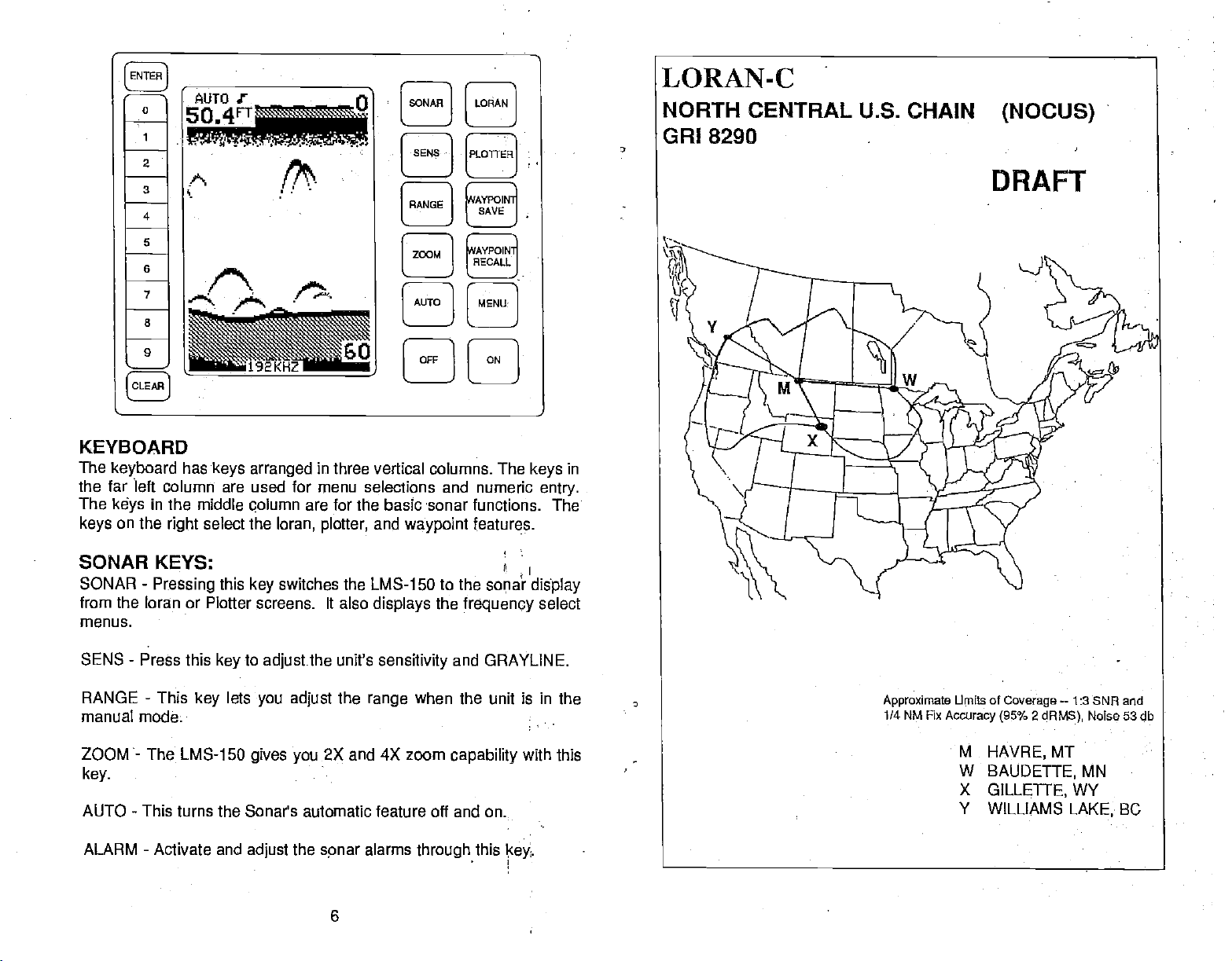
KEYBOARD
The
keyboard
the far left column are
The
keys
on the
keys
SONAR KEYS:
SONAR
from the loran or Plotter screens. It also
menus.
SENS
manual mode.
-
RANGE - This
has
in the
middle
select
right
-
Pressing
Press this
key
keys
this
key
lets
arranged
used for
qolumn
the
key
to
adjustthe
you adjust
in three vertical columns. The
menu
are for the basic sonar functions. The
loran,
plotter,
switches the LMS-150
unit's
the
H
[AUTOI
4
[METZI]
[OFFILON]
selections and numeric
and
waypoint
displays
sensitivity
when the unit is in the
range
features.
to the
the
frequency
and
keys
I
sopa? display
GRAYLINE.
in
entry.
select
ZOOM-
key.
AUTO - This turns
ALARM - Activate and
PDF compression, OCR, web-optimization with CVISION's PdfCompressor
The
LMS-1 50
gives
the Sonar's automatic feature off and on.
adjust
2X and 4X zoom
you
the
spnar
6
alarms
through
capability
this
cey
with this
Page 11
Loran
KEYS:
Note: This
was
is an
computed
atmospheric
"UnoflicialPreljminaw Coverage
using conservative
and
noise,
grid
estimates
geometry.
Diagram".
of station
range
Coverage
limits,
-
The ON
-
The Off
NOTE.
modes
key
the
first
-
Press
-
KEYS:
-
This
You
while the
Pressing
plotter
LORAN
PLOTTER
WAYPOINT
WAYPOINT
OTHER
ENTER
CLEAR - Use
ON
OFF
MENU KEY
three
MENU
appears
up
this
This
key
SAVE
key
switches
-
Press
to
RECALL - This
is
used to
key
this
key
key
must
-
This
-
sonar,
to
key
turns
erase a
the
turns the
press
activates the first
key
loran,
sonar
the
MENU
menu
screen.
switch to
the loran
the LMS-150 to
this
key
LMS-150 on.
LMS-1 50 off.
and hold
and
screen is
to
key
activates the
enter
selections from
previous
the OFF
plotter.
while the
key
displays.
the
save
waypoints.
waypoint
keystroke
key
menu
For
example,
displayed,
plotter
plotter
menus.
to turn the
or
display.
recall
menu.
menus.
unit off.
screen for each of
if
the
you press
first sonar
is
displayed brings
menu
the
the
DISPLAy
The
lights
150
on. Menus
the
key
It controls
don't
turn off.
them
The
Metric
the
nautical
adjacent
want the
The
off at
Metric menu
label to
temperature
miles.
-
General
are on
for
appear
to the
the
backlighting
lights
menus
time
ny
works the
change
display
about ten
at the
Light
used on
wait
on,
also
disappear
by
pressing
the
depth
to
degrees
seconds
same lime. To
label.
ten seconds
the CLEAR
same
way.
from feet to
when
you
keep
(Seethe
the
picture
display
and
and the
after
ten
seconds. You
key.
Press the
meters. This
Celsius, speed
first
turn the LMS-
the
lights on,
on the
keyboard.
lights
next
automatically
can turn
key adjacent
also
to
knots,
changes
and
prçss
page.)
If
you
to
the
log
7 PDF compression, OCR, web-optimization with CVISION's PdfCompressor
to
Page 12
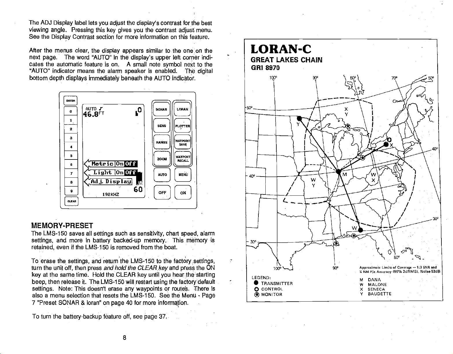
The ADJ
Display
label lets
viewing angle. Pressing
See the
Display
Contrast section for more information on this feature.
you adjust
this
key gives you
the
display's
contrast for the best
the contrast
adjust
menu.
After the menus
next
page.
cates
the automatic feature is on. A small note
"AUTO" indicator means the alarm
bottom
The word "AUTO" in the
depth displays
0
2
3
4
5
B
7
B
9
clear,
immediately
the
display appears
beneath the AUTO indicator.
similar to the one.on the
displays upper
speaker
is enabled.
left
symbol
corper
indi-
net to the
Th,é
digital
LORAN-C
GREAT LAKES CHAIN
GRI 8970
MEMOR V-PRESET
The [MS-i 50 saves all
settings,
retained,
To erase
turn the
key
beep,
settings.
and more in
even
if the [MS-i 50 is
settings,
the!
unit off,
then
at the same time. Hold the C[EAR
then release it The [MS-ISO will restart
Note: This doesn't erase
settings
battery backed-up
and
press
also a menu selection that resets the [MS-i 50. See the
7 "Preset SONAR & loran" on
To turn the
battery-backup
PDF compression, OCR, web-optimization with CVISION's PdfCompressor
such as
removed
return
sensifivity,
memory.
from
the [MS-ISO to the
and hold the CLEAR
until
key
any waypoints
40 for more
page
fOature
off,
see
page
8
chart
speed,
This
mèhiory
boat.
the
factory settings,
key
and
press
the ON
you hearthestarting
the
using
factory
or route.
Menu
T!!here is
informaion.
37.
alarm
is
default
-
Page
Page 13
FREQUENCY
Lowrance
The 192 kHz
fish,
192 kHz
as
go
50s. You can
offers both 50 and
frequency
structure,
and bottom
doesn't
deep. Also,
draw a few
SELECT
typically
definition better than
penetrate
192 kHz cone
water
conclusions from
192 kHz
has
transducers for the [MS-I 50.
superior target
as well as 50
angles
are
resolution,
50 kHz.
kHz,
typically
However,
therefore it
narrower than the
these statements.
showing
the
won't
Note:
This is an
was
computed using
atmospheric
"Unofficial-Preliminary Coverage
noise,
conservative
and
grid
estimates of station
geometry.
Diagram".
range limits,
Coverage
1. Use 192
cone
angle
narrow
deep depths.
2.
Use the 50
desired:
see the
both
a30
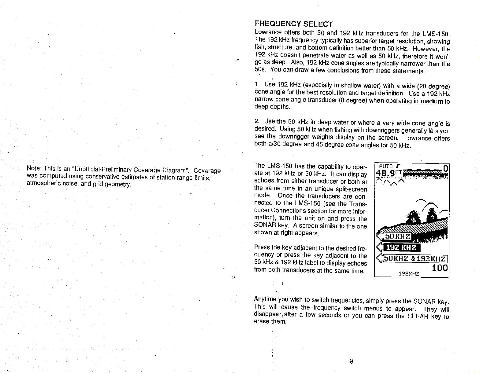
The
LMS-150 has the
ate at
echoes from either
the
same time in
mode.
nected to the
ducer
Connections section
mation),
SONAR
shown at
Press the
quency
50
kHz & 192 kHz
from both
kHz
(especially
for the best
cone
angle
kHz in
50
Using
downrigger weights
degree
kHz or 50 kHz.
192
Once the
[MS-i 50
turn
the unit on and
A screen
key.
right appears.
key adjacent
or
transducers at
press
the
in shallow
resolution and
transducer
deep
kHz when
and 45
capability
(8
water
fishing
display
degree
It can
degree)
cone
to
display
transducer or both
an
unique split-screen
transducers
(see
are con-
the Trans-
for more infor-
press
similar to the
to the
desired fre-
key adjacent
label to
display
echoes
the same time.
water)
definition.
target
when
or where a
with
downriggers
on
the screen.
angles
oper-
at
the
one
to the
with a wide
operating
wide cone
very
generally
Lowrance offers
for 50 kHz.
(20 degree)
Use a 192 kHz
in
medium to
is
angle
lets
you
Anytime
This
will cause
disappear;
erase
them.
PDF compression, OCR, web-optimization with CVISION's PdfCompressor
you
after a
wish to
switch
the
frequency
few seconds or
frequencies,
switch
you
9
simply press
menus to
can
appear.
press
the SONAR
the
CLEAR
They
key
key.
will
to
Page 14
AUTOMATIC
When
the LMS-150 is
is shown
feature
shows in the lower
To turn
UAL"
Automatic
AUTOMATIC
the
by
adjusts
Automatic
appears,
on,
MODE ON
word "AUTO" at the
the
showing
press
first turned
sensitivity
half of the screen.
off, simply
the unit is in
the AUTO
on,
and
press
key
range
again.
the
Automatic feature is
of the screen. The
top
so the
the AUTO
bottom
key.
the manual
on. This
Automatic
signal 'always
The
word"MAN-
mode.
To turn
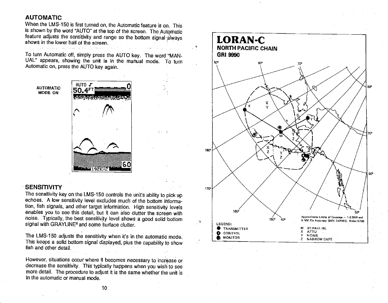
LORAN-C
NORTH
GRI 9990
10
PACIFIC
CHAIN
SENSITIVITY
The
sensitivity key
echoes. A low
fish
tion,
enables
noise.
signal
The LMS-1 50
This
fish and other
However,
decrease the
more
in
the automatic or manual
signals,
you
Typically,
with GRAYLINE®
a solid bottom
keeps
situations
detail. The
on
sensitivity
and other
to see this
the best
adjusts
detail.
sensitivity.
procedure
the LMS-1 50 controls the
level excludes
target
detail,
and some äurface clutter.
the
occur where it becomes
but it can also clutter the
sensitivity
sensitivity
signal
displayed, plus
This
typically happens
to
adjust
mode.
10
much of the bottom
information
level shows a
when
it's in the automatic
it is the same
unit's
ability
High
sensitivity
good
the
capability
necessary
when
you
whether the unit is
to
pick
up
informa-
levels
screen with
solidbottom
mode.
to show
to increase or
wish to see
1700
PDF compression, OCR, web-optimization with CVISION's PdfCompressor
Page 15
To
adjust
menu
appears
menu is
the
sensitivity,
on
the left side of the
immediately
press
beneath
it.
the
SENS
screen. The
key.
The
sensitivity adjust
GRAYLINE®
adjust
NORTH PACIFIC LORAN-c
REGIONAL MANAGER
CHAIN
MANAGER: COMMANDER.
COORDINATOR OF CHAIN
CONTROLSITE
05010.
MASTER
XPAY
YANKEE
20W
LORMCNSTA
STAT I4
ST. PAUL
M
AOl' U
*0K
PORT
CLARENCE
1*0
NARROW
CAPE,AI<
COMMANDER.
CHAIN CR1 9990
OPERATIONS LOCATION:
PACIFIC AREA.
17TH COASIGUARD
AK
KODIAK,
095U.
COOP.
5700 12.314
1701500,5W
524 E
073 lO40.OE 2075,32
5514402W 2S0501
150531a0W 2050.05
072520.214 43032'
15205112W 3500.45
coo)
44.EN I 1032'
ALAMEDA,
LORMONSTA
XMITTER
AI4FPN-42 325
MUppN.42 1000 1350 FT
AN'FPN-4lA '400
CA
DISTRICT. JUNEAU AK
KCDIAK, AK
PWP
KW)
025
MOW OPOL S
TEANSM,T1 NM
ANTS4NI& J SOD
525
Ma4CPOLE
505
MQOP,E
MON OPOLE
825 FT
PT
PT 0.0
0.0
+2.0
0.0
DUAL RATE W/SP 7050
NOTES
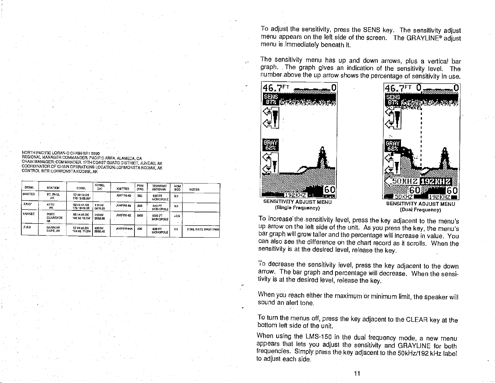
The
sensitivity
graph.
The
menu
graph gives
numberabove the
46.7ET
'2KHZ n-
SEN5ITIvITy ADJUST
(Single
Frequency)
To
increase' the
arrow
up
bar
graph
can
also see the
sensitivity
on the
will
grow
is at the
-sensitivity level,
left side of the
has
and down
up
an indication of
arrow
up
shows the
60
—.
MENU
-
press
unit. As
taller and the
difference on the
desired
level,
percentage
release the
arrows,
the
sensitivity
percentage
SENSITIVITY ADJUST MENU
the
key adjacent
you press
will
increase in value.
chart record as
key.
a vertical bar
plus
level. The
of
sensitivity
(Dual Froquency)
to the
the
key,
in use.
menu's
the menus
You
it scrolls. When the
To
decrease the
arrow. The bar
is at
tivity
When
sound
To turn
bottom
When
appears
frequencies.
to
adjust
the desired
reach
yu
analert tone.
the menus
left side of the
using
that
each
sensitivity level,
and
graph
level,
either the
off,
press
unit.
the
LMS-150 in the
lets
you adjust
Simply press
side.
percentage
release the
maximum or
the
key
the
the
key adjacent
PDF compression, OCR, web-optimization with CVISION's PdfCompressor
the
press
key adjacent
will
decrease. When
key.
minimum
adjacent
dual
frequency mode,
sensitivity
and GRAYLINE
to the 50kHz/i 92
11
limit,
to the
to the down
the
speaker
CLEAR
a new menu
the sensi-
will
at the
key
for both
kHz label
Page 16
GRAVLINP
GRAYLINBTh lets
"paints"
allows
example,
you
displays
which causes a wide
signal
on
gray
to tell the difference
a
soft,
with a narrow or no
you distinguish
targets
muddy
that are
or
weedy
gray
between
stronger
strong
and weak echoes. It
than a
preset
value.
between a hard and soft bottom. For
bottom returns a weaker
line. A hard bottom returns a
gray
line.
signal
This
whibh
strong
If
without,
guish
GRAYLINE® is
between
have two
you
the
signals
target
weeds from trees on
adjustable.
strong
and weak
with
a different GRAYLINE®
at
power
your
on is
usually
unit to find the
GRAYLINE
46,IFT
.
SElls
of
equal size,
is the
gray
the
bottom,
Since GRAYLINE® shows the difference
signals,
also. The level chosen
level,
adequate
for
setting
one with
stronger signal.
or fish from structure.
adjusting
most conditions.
the
sensitivity may require
that's best for
and the other
gray
This
the LMS-15O
by
Experiment
you.
A
helps
distin-
with
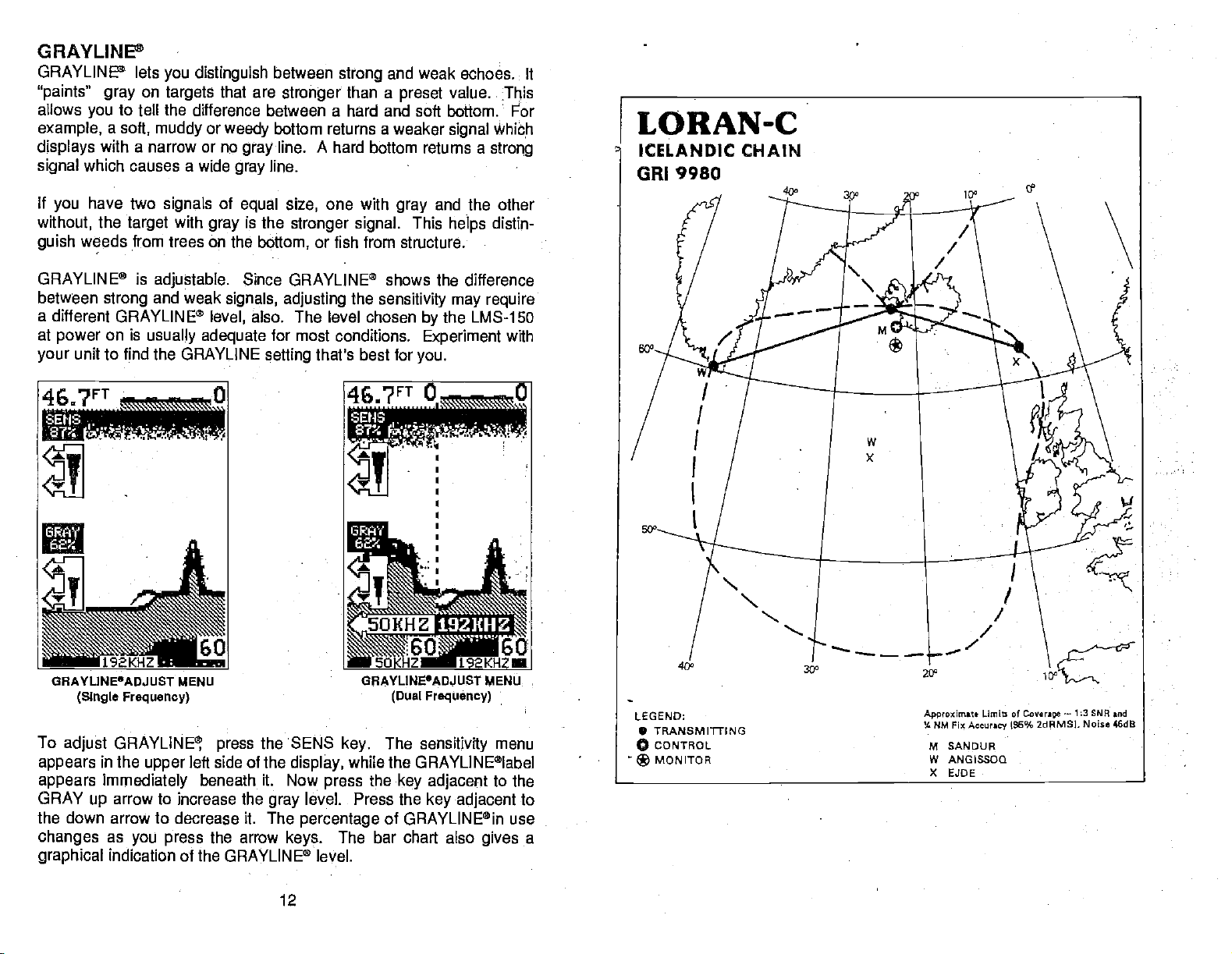
GHAYLINE°ADJUST MENU
(Single Frequency)
To
adjust GRAYLINE
appears
in the
upper
appears immediately
GRAY
arrow to
up
left side of the
beneath
increase the
press
the SENS
it. Now
gray
the down arrow to decrease it. The
changes
graphical
as
you press
indication of the GRAYLINE® level.
the arrow
12
display,
level. Press the
percentage
keys.
GHAVLINE'ADJUST MENU
(Dual Frequency)
The
key.
sensitivity
while the GRAYLINE®label
the
press
key adjacent
key adjacent
of GRAYLINE®in use
The bar chart also
menu
to the
gives
to
a
PDF compression, OCR, web-optimization with CVISION's PdfCompressor
Page 17
You can see the
chart
meni;
ecord)
press
as
the
change
you press
on the
the
key adjacent
screen
keys.
to
the CLEAR
on the menu and
(both
After
you've
to erase
key
made the
the menu.
on the
adjust-
•
ICELANDIC
REGIONAL
Cl-lAIN MANAGER
COORDINATOR OF CHAIN
cortrnOLsITE:LORMONSTAKEFUVIK ICELAND
MASTER SMDUR
XMY
LORAN-C CHAIN
MANAGER.
STArn4 C(9.
-
iCAND
N4 255cc
OREBILAND
E3OEFAEAOE
S..DEFLWOc
GR1 9980
COMMANDER COAST
COMMANDER COASTGUARD
OPERATIONS LOCATION
cai.
6454 20R4
815521.0W
5959 97a54
4596 276W
6217 59Th 3OW
07 9426.5W 2544.54
81) XMTEEF
I 90
4006. 1fl40'Ot.E
GUARD
ACTIVITIES
ACTIVITIES
LORMONSTA
AMFJ'N-45 5O
AN/FN4S 700
UF904-44 3 625
MCfl0PoI.E
EUROPE, LONDON,
EUROPE, LONDON,
KEFLAVLK, ICELAND
PWR
I TAANSMI
MTUIM&
)KW
I 1250F7
I
I FT
FT
UK
UK
NG4
LCD
0.0
0.8
—
NOTES
OMAL flATS
DLLALRATE
W(0R17970
ORI?970
RANGE
When
signàl.in
is
part
the
RANGE
The
mode.
To
chang
mode,
mode:.
left
the
key
-
first turned
the lower
of The
un is in
-
LMS-150
-Bdth
If
hecessary, press
Next,
corner
of
corresponding
increase the
150,
(Metrio.
600,
the
CLEAR
?00,
ranges
1q00,
300,
and
Automatic
the LMS-150
on,
half of the
automatic function. You
automatic.
Manual
gives you
the lower and the
the
press
the
range.
are
key
range,
1500
first make
the RANGE
display.
to the
The available
500, 800,
3,5, 10,
meters.)
to
erase the
screen. This is called Auto
control over
upper
the AUTO
These are the
Shallower or
1000, 1500, 2000, 3000,
15, 20, 30, 40, 60,
After
range
1.311
automatically places
cannot
the
range
limit are
change
when it'á in the
adjustable.
the
certain the LMS-150 is in
key.
ranges
to switch
key
Two arrows
range
adjust
Deeper
are
0-5, 10, 20, 40, 60,
to the manual
appear
arrows..
arrow
to decrease or
and
100, ISO, 250, 300,
you've
set the desired
arrows.
A
the bottom
Ranging
range
the manual
and
while
manual
in the lower
Press
100,
5000 feet.
400,
range, press
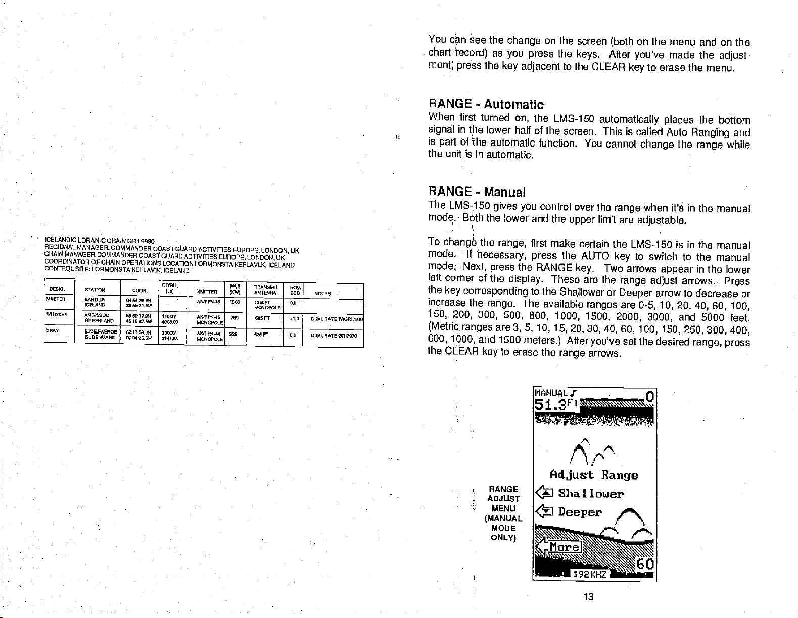
Adjust
•
RANGE
ADJUST
MENU
(MANUAL
MODE
ONLY)
Shallower
Deeper
PDF compression, OCR, web-optimization with CVISION's PdfCompressor
Range
13
Page 18
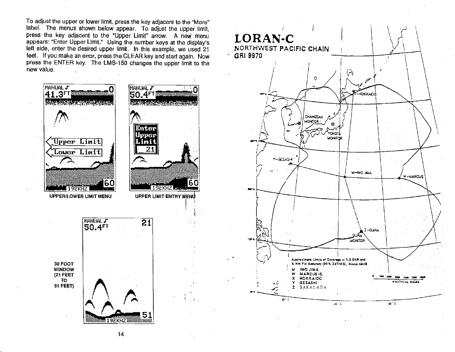
To
adjust
label.
press
appears:
left
feet. If
press
new value.
The menus.
the
side,
you
the ENTER
theupper
key adjacent
"Enter
enter the desired
make an
or lower
shown below
error,
key.
Limit."
The
Upper
to the
limit,
"Upper
Usingthe
upper
the CLEAR
press
LMS-1 50
the
press
appear.
limit. In this
key adjacent
To
Limit" arrow. A ne menu
number
changes
adjust
keys
example,
and start
key
the
to the "More"
the
upper
at the
we used 21
again
limit to the
upper
limit,
display's
Now
LORAN-C
NORTHWEST
GRI 9970
PACIFIC CHAIN
MANUALY
___________
7..
UPPERILOWER UMIT
MNuALr
5O4rT
MENU
0
UPPER UMIT ENTRY
21
30 FOOT
WINDOW
FEET
(21
To
51
FEEl]
Anrssi,r'nt Limit ,4
NM Fl,
Lwri (15% 2dM$(.
V
(WOJIMA
W MACUSIS.
X
IOKKAIDO
V
GESASNI
Z BARAGADA
tonr.q.
—
No.s• flat
$NM nd
a a
'aUflCaa. 'ILI.tS
a
-L
-a'-51
PDF compression, OCR, web-optimization with CVISION's PdfCompressor
192
14
Page 19
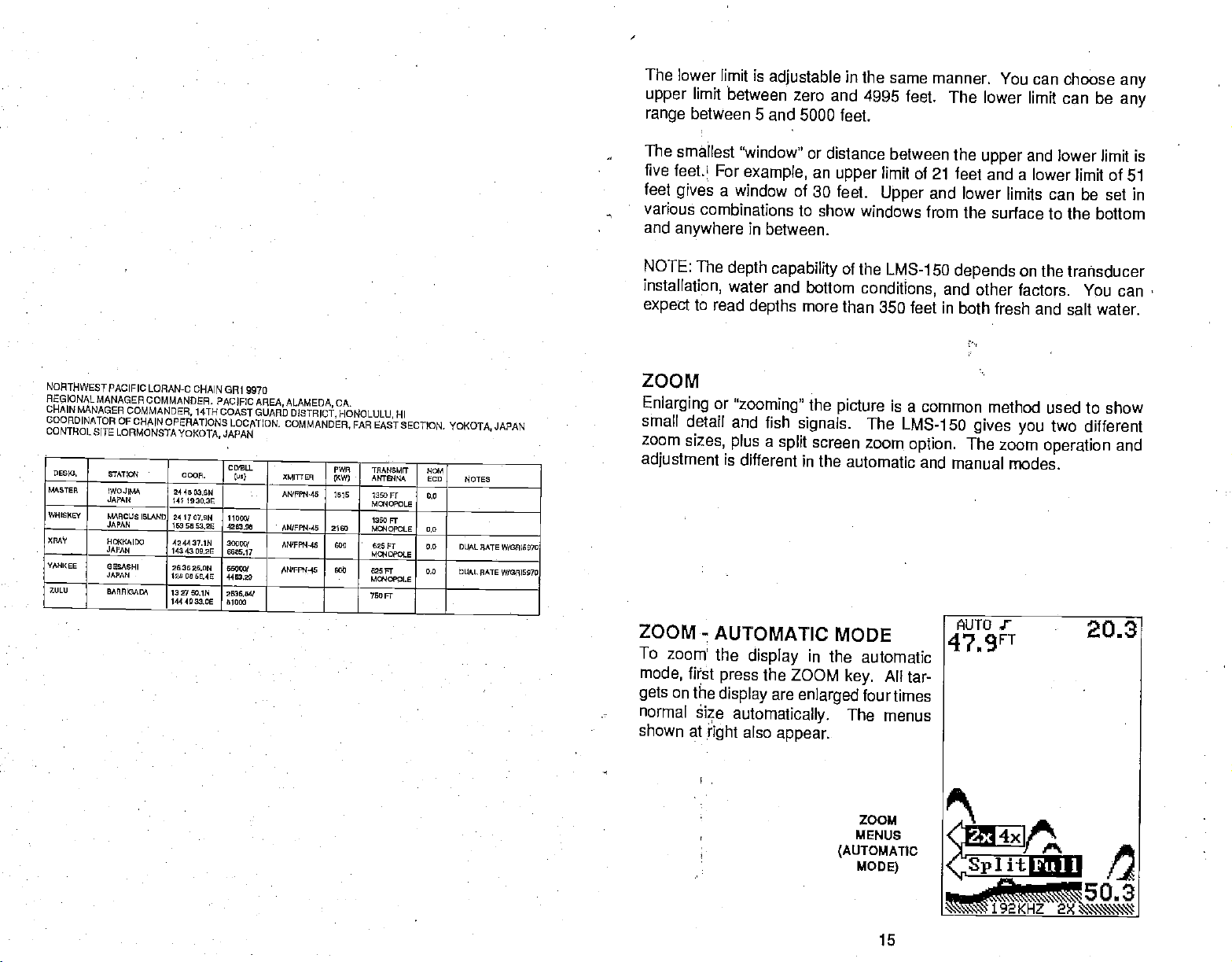
The
lower limit is
limit
upper
range
The
smallest 'window'
between zero
between 5 and
five feet.L For
feet
various
and
a window of
gives
combinations
anywhere
adjustable
example,
to show windows
in
between.
in the same manner.
and 4995 feet. The
5000 feet.
or
distance between the
an
30 feet.
upper
limit of 21
Upper
You can choose
lower limit can be
and lower limit is
upper
any
any
feet and a lower limit of 51
and
lower limits can be set in
from the surface to the bottom
MORTHWESTPACIFIC LORAN-c
REGIONAL
CHAIN
COOROINATOR OF
CONTROL SITE
M'0TER
YANKEE
MANAGERCOMMANDER.
MANAGER
0 ES
00.
ETAT0ON
IWOJIEM 24 40
JAPAN
EMECU0 ISLAND
JAPAN
NCKMIDO
JAPAN
OESAEHI
JAPAN
EAPRISADA 1327 LOiN
COMMANDER, 14TH
CHAIN OPERATIONS
LORMONSTAYOI<OTA,
COOP.
040 1930!3E
24 17 OVEN II 000/
003 5003.25 4003.00
424437.IN
143430E.2E
26312L0N 000
000 00 01,40 4403,00
144 4033.00
CHAIN GRI 9970
PACIFIC
AREA,ALAMEDA,
COASTGUARO
LOCpmCN.
JAPAN
C DELL
lu.)
03EN
30000f
0036,041
81004
CA.
DISTRICT, HONOLULU, HI
COMMANDER,
XMITT 10
ANPFII'40 IBIS
________
AN/0P04.40 2000
AN'FFl4.I5 000
_________
NN0FFRA-40 800 020
PWR
0(W)
FAR
EASISECTION,
TRANSMIT N0,I
-
ANTBIM
Isoor
Ma4OPOL0
1300 FT
MCNOPOLE 6.0
625 FT 0,0
MCNCPOLI
FT 0.0 DUAL
M4CLE
700 FT
JAPAN
YOKOTA,
NOTES
DUAL RATE W00000070
PATE W/0R15070
NOTE: The
installatipn,
to
expect
read
ZOOM
Enlarging
small detail
zoom
sizes,
adjustment
ZOOM
To zoom!
mode,
gets
normal
shown at
-
fi?st
on the
èize
right
depth capability
water and bottom
depths
or
"zooming"
and fish
plus a split
is different in
more
the
signals.
screen zoom
the automatic
AUTOMATIC
the
display
press
display
automatically.
also
in the automatic
the
ZOOM
are
enlarged
appear.
of
the LMS-1 50
conditions,
than 350 feet in
picture
is a common method
The LMS-150
option.
and manual modes.
MODE
All tar-
key.
four
times
The menus
depends
on the transducer
and other factors. You can
both fresh and salt water.
used to show
two
gives you
The zoom
different
operation
and
ZOOM
MENUS
(AUTOMATic
MODE)
PDF compression, OCR, web-optimization with CVISION's PdfCompressor
15
Page 20
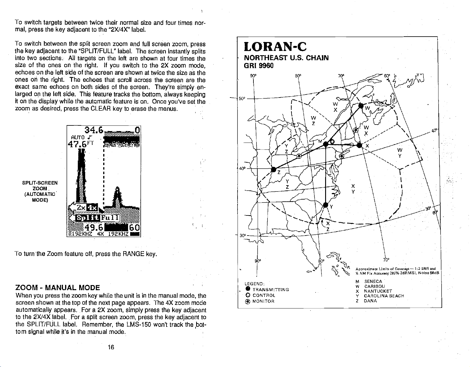
To
switch
mat, press
targets
the
key adjacent
between twice their normal size and four times nor-
to the "2X14X" label.
To switch between the
the
key adjacent
to
the "SPLIT/FULL" label. The screen
into two section& All
size of the ones on the
echoes on the left side of the screen
ones cii the
right.
The echoes that scroll
screen zoom and full screen
split
targets
right.
on the
If
you
are
left
switch
are shown at twice the size aâ the
across the screen are the
shown at four times the
to the
exact same echoes on both sides of the screen.
larged op
it on the
zoom as
SPLIT-SCREEN
ZOOM.
(AUTOMATICS
MODE)
the left side. This
display
desired,
while the
press
feature tracks the
autQrnatic
the CLEAR
featureis on.
key
bottom,
to erase the menus.
zoom,
instantly splits
2X
zoom
They're
Once
simply
always keeping
you've
press
mode,
en-
set the
To turnthe Zoom feature
off,
press
the RANGE
key.
ZOOM - MANUAL MODE
When
you press
screen shown at the
automatically appears.
to the 2X/4X label. For a
the SPLIT/FULL label.
tom
while it's in the manual mode.
signal
the
zoom
key
of the next
top
For a 2X
split
Remember,
while the unit is in the manual
page appears.
zoom,
screen
zoom,
simply press
The 4X zoom mode
the
the
press
key adjacent
key adjacent
the LMS-150 won't track the bot-
16
mode,
the
to
I
PDF compression, OCR, web-optimization with CVISION's PdfCompressor
Page 21

34.0
MAF4UItS
46.8FT
U
I
I
•
NORTHEASTLJ,s,
•
OHAINMANAOERCOMMANDERATLANTICAREANEWYORKNY
•
000RDINATOROFCHAINOPERATIONSLOCATION:LORSTASENECANY
CONTROLSITE:LORSTASENECA,Ny
DI0. ETATfll
_____
ZILU
LORAN-C CHAIN
COMMANDER, ATLANTIC AREA
S6WEJff
OAAEOO,ME
_______ ______
NO
BOSCH.
OAIOAIN
CR19960
ODOR.
424250.6W
764923.9W
19462724 11050/ ANFFF4-42
67 B537.7W 279720
4105 lION 26050t
0)9039.1W
340346104 3000W
7754497W
______
3959 076W 0400W
072012.9W 310220
099L1. P9W
so) XMIUOA
1999.93
2320.64
NEWYORKNY.
-
TRANSkET WOW
- ______
AN'FP04-64 700 Fl
(56H0020) M000ROLE
AN'FF74-13
APO'pE14-42 650 TIP
______
AN'F6W44 450 025
094 AFIT94W EUD NOTES
SLT 0.0
025Fr 0.9
MOSDPOA.E
______
Ft -0.5 DUAL RATE
MOO4DPOO.E
—
0.0 DUAL RATE VOOF '0070
DUALRATEW(0RI5930
DUALMATEW/0415030
0.0 DUAL RATE
V/0FF796E
__________
41109
5570
192KHZ 4X
SPUT-SCREEN
(MANUAL
T
o a
screen
appears
the
bottom left.
ones
that
keys
adjacent
adjust
the same
erase a few
To
keep
unit is
label
two times. The
bottom of the
the manual
zoom
e
jus
zoom, press
similar to the
at the
top right
The echoes on the left
appear
to the
the
zoom
time. The zoom
seconds after
the zoom bar
the manual
!n
screen. This
mode.
bar.
Repeat
MEN US
The
LMS-15O uses
tions
and features of
features, allowing
and
water
conditions. If
CLEAR
are
seven menus on
available
This
key.
through
192KHZa
ZOOM
MODE) REGIONALMANAQER
In
e
one at the
side of the screen
between
and bottom of
top
arrows to move the
the
bar,
echoes move on
adjust
you've
on the
mode.
"Display
Press the
these
menus
screen,
Next,
Zoom
menu
key adjacent
steps
extensively
the unit. The
to
you
returns the
customize the unit to
ever
you
LMS-15O to the last used
the sonar side.
the menu
key.
ZOOM
ADJUST MENU
(MANUAL
k
a
ey
upper right
jacen
and
4
h
0
e a e
appears.
adjust
side of the screen are the
the zoom bar.
zoom bar
the left side of the screen
menus and zoom
the
pressed
press
press
last
the MENU
the
key adjacent
Window Bar" menu
only appears
to
turn the zoom window
to
menu
when the
to
this menu to
guide
you through
accesses
key
your particular
lost in a
get
All of the
following
MODE)
ADJUST I b I A
A zoom
arrows
or down. As
up
bar
key.
appear
same
Press the WHTOKEI
automatically
while the
key
to the "More"
appears
LMS-150 is in
bar
at the
display
9ff
the func-
of tltese
many
needs
menu,
simply press
screen. There
features are
bar
at
you
at
the
PDF compression, OCR, web-optimization with CVISION's PdfCompressor
17
Page 22

MENU
-
PAGE 1
CHARTSPEED
Chart
speed
first
by
"ADJUST
the
left side
key
adjacent
to
the
the
arrow
indication of
(both on the
After
you've made the
to
key
The
chart
turned
pressing
CHART
down
keys
erase
speed
on.
is the
the
of the
to the
arrow.
are
the
chart
menu
the
menu.
rate
echoes
menu
SPEED"
screen.
arrow.
up
The
pressed. The bar
speed, You can
and on
adjustment,
is
preset
scroll
then
key,
label. The
Increase the
Decrease it
percentage
the
chart
to
maximum
across the
pressing
chart
of
chart
seethe
record)
the
press
the
speed menu
chart
by
pressing
speed
chart
also
as
key
adjacent
when
screen.
key
speed
in
gives
change
you
the
LMS-lso is
It's adjustable
adjacent
by
the
key
use
to the
appears
pressing
adjacent
changes
a
graphical
onthescreen
the
press
to the
keys.
CLEAR
on
the
as
first
LORAN-c
U.S.
GRI
WEST
9940
COAST
CHAIN
To
Repeat
stopped, then the
screen.
stop
the
this
This
chart,
step
gives
to start
Menu
LT
Adjust
Chart_Speed
More I
the
press
CLEAR
a
clear viOw
key adjacent
the
chart
key pressed
of the
1
Pg.
H
again.
display.
to
If
to
the
"START/STOP" label.
desired,
erase
the
chart can
the menus
from
50
be
the
40'
MENU-ist
PAGE
18
cHART
SPEED
ADJUST
MENU
PDF compression, OCR, web-optimization with CVISION's PdfCompressor
Page 23

FISH l.D.
The
Fish l.D. feature
fish. The
micro-computer
clutter, thermoclines, and other
instances,
symbols
four
relative size
symbol
a
largertarget,
remaining targets
on
the screen in
fish
symbol
between
when ft thinks a
sizes:
etc.
identifies
analyzes
are fish. The Fish
place
tiny, small, medium,
targets.
is a small
target
targets
that meet certain
all echoes and
signals
that are undesirable. In most
of the actual
In other
words,
fish,
eliminates surface
l.D. feature
fish echoes.
and
large.
it
displays
a medium fish
conditions as
displays
There are
These show the
a small fish
symbol
on
U.S.
WEST
REGONAL MANAGER
CHAIN MANAGER
COORDINATOR
CONTROL S ITE:
COASTI.ORAN.C CHAIN CR1
COMMANDER. PACIFIC
OFCHAIN OPERATIONS
LDRSTA
ETATIGM
FAtLON, IN
GEORGE, WA
MWLETOWI4
CA.
SEARCHLIGHT
IN.
00001.
50.4W
9940
AREA,
LOCATION
COED.
lu') XMITTER
2750Sf
420591
COMMANDER. PACIFIC
MIDDLETOWN. CA
5933 SEEN
11040
470340GM 100W
I 1044 30.5W 2706.00
304657GM
1032944.504 1004.50
351015.201
1144El7.4W 1007.30
AREA
ALAMEDA, CA
ALAMEDA, CA
LORSTA MIDDLETCWN CA
OWE
II<VO AN1'EIlItA SOD NOTES
A040FPN'44A
AI4'FFN-45 ' SLT
AN'FPN.44A 400 525
MGMOPOLE
AN'FPN-44 540 SLT
400 025
I
TRANSMIT MOM
Fr +1.0
Mc*1000LE
+0.0 DUAL RATE 04/12510000
Fl +0.5
0.5
The
micro-computer
distinguish
turtles,
outwards from
ing
ID.
feature to
the
screen when
between
submerged floats,
both the Fish
Fish I.D.
When the
Fish
adjacent
pears
across the
feature.
LMS-150 is turned
ID.
feature
to
the 'Turn On
and
the sonar
screen, however,
•
Chart
is
sophisticated,
fish and other
a
group
distinguish
actually,
l.D. mode and
on, first
Fish-ID"
screen returns.
Menu
Adjust
Speed
but it can be
suspended
air
bubbles,
of
limbs is the hardest
from fish.
etc.
You
may
there are no fish.
without to become
the Fish ID.
on,
the
press
MENU
label. The menu
Echoes will
the
surface clutter no
AUTO J
52.0F1
objects
Individual
such as
tree limbs extend-
object
see
Fish l.D.
Practice with
more familiar with
feature
key.
is off. To turn the
Now
immediately
continue to
longer
fooled, It
trotlines,
for the Fish
symbols
the unit in
the
press
shows.
—--0
can't
on
the
key
disap-
scroll
Any
SONAR
4 __________________
La
_1.:ti0re
PDF compression, OCR, web-optimization with CVISION's PdfCompressor
Alarns
I
1 60
FISH 1.0. ON
19
Page 24

targets
the
micro-computer
determines are fish show as fish
To turn the Fish I.D. feature
press
AUTO
the
key.
adjacent
key
This turns the Fish l.D.
to
the
same time.
Remember, you
the manual
150 is in
If
you
manual,
turn automatic off when
can't use the Fish 1.13. feature
mode.
If
turn the
you
the
micro-computer
feature will be turned off also.
CHART CURSOR
The LMS-1 50 has a
depth.
display
side
The cursor is
from left to
shows the line's
at 16.1 feet.
chart cursor that allows
simply
right. A depth
depth.
off
again,
'Turn
first
Off Fish-ID"
feature and automatic off at the
press
the menu
label. Or
when the LMS-150 is in
I.D. feature on when
Fish
will
turn the automatic
the Fish LD. feature
you
ison,
to
pinpoint
a horizontal line that extends
box at the end of the line on
In the
example
below,
the cursor
symbols.
key. Next,
the
press
the LMS
a
target's
the
right
(line)
on.
is
featçire
the Fish Iii
across the
LORAN-C
MEDITERRANEAN CHAIN
GRI 7990
5Q0
To
display
adjacent
one below
Use the
or down to the desired
To turn the chart cursor
MENU
the chart
to
"Turn
the
appears.
keys adjacent
Now
key.
press
cursor,
press
the MENU
key.
Now
press
the
On Chart Cursor" label. A screen similar to the
to
the
depth.
the
and down arrow to move the cursor
up
off, press
the
key adjacent
key
up
40°
to the "Turn Off Chart Cursor" label. The
LMS-1 50 returns
out the chart
NOTE: You cant use the Chart Cursor
when FASTRAK is on.
to the sonar screen with-
cursor.
20
M SELLIA MARINA
LAMPEDUSA
X
V KARGABURUN
Z ESTARILT
PDF compression, OCR, web-optimization with CVISION's PdfCompressor
Page 25

ALARMS
The LMS-15o
sounds when the Fish ID.
fish.
Another alarm is the
echo that
the Bottom Alarm.
useful as an anchor
has three different
appears
inside this bar
Only
watch,
the bottom
of alarms. The Fish
types
feature determines a
Zone Alarm
a
shallow water
which consists of a bar.
triggers
signal
the alarm. The last alarm
will
"trip"
alert,
of echoes is a
group
this alarm. This is
or for
navigation.
Alarm
Any
is
MEDITERRANEAN SEA
REGIONAL MANAGER
CHAN
MANAGER
COOROINATOR
CONTROL SITE:LORSTA SELLIA
LORAN-C CHAIN SRI 7990
COMMANDER, COAST$UARO
COMMANDER. COAST GUARD
OFOHAIN OPERATIONS
SELLLk
9.S9INAjrALy
LAM P EDU BA
6Th LV
KAFOABURLIN
TU9IcE'
ESTAPTIr
SPAN
LOCATION:LORSTASELLIA
MARINA, ITALY
C
0009. u.9
OS LI
ACTIVITIES EUROPE,
ACTIVITIES
EUROPE,
TIMFUER
AWFPN-29
ATLE
AM'FPN -29
ANTFFN-39 166
LONDON,
LONDON,
ITALY
MARINA,
Pw# TRANEMIE
ANTENNA
IKWI
169
BOEFE
225
MON
165
OPOLE
629 FT
MOACPCLE
E2EF1 an
MON
OFOLE
All of the
signal
Depth
The
echo will
when
deep
set
UK
UK
deep
Shallow
NO.1
ECD
NOTES
6-c
-
2.0
0.0
To use
key
appears,
The
press
the one
alarms have a visual
can be
Alarms
Depth
"trip"
bottom
the
alarm
point.
Use
alarm
Alarm
the Shallow
adjacent
Shallow
the
key adjacent
shown at the
Chart
4
turned off
Alarms are
this alarm.
sounds when the
the shallow
to alert
to
the "Sonar Alarms"
and
Deep
Menu
through
only triggered
signal 'goes
alarm to warn
to
you
deeper water,
Alarm,
Alarm
to
the 'Set
of
top
Pg.1
Adjust
Speed
Turn
Fish—ID
On
and audio
the ALARM
signal.
menu.
from the bottom
The shallow
alarm, sounds a
shallower than the alarm
bottom
signal goes
of
you
deeper
shallow water. Use the
such as a
first
menus are at the
the next
the
press
MENU
label. The screen below
top
Shallow" label. The screen
page
appears.
ALARMS MENU
Depth
i4s
Set
Zone
1.
__iirrn.—J
II
Li
Turn
—
Fish
•_
Turn
If
desired,
signal.
drop-off.
key.
the audio
warning
set
point.
than
the alarm
Now
press
No other
tone
The
the
right
of this screen. Now
similar to
Alarms
rn a ru
Deep
Alarm
On
Alarm
On
1
I
r.
Li.,.
PDF compression, OCR, web-optimization with CVISION's PdfCompressor
21
ALL Alarms
':.HTttibfl Off
K.
Page 26

Now
appears
the desired shallow
screen.
press
"Enter
the
key adjacent
Shal
Alarm",
alarm
to the
"Enter
as shown above
depth using
the
Depth"
arrow. A new menu
Now
right.
on the left side of the
keys
Auto,
SHALLOW ALARM MENU SHALLOW ALARM ENTRY
MENU
simply
ent&
This
example
depth
goes
the
Enter
ALARM"
turns the shallow alarm on.
a
tone sounds and the words "SI-IAL
arrow
appears
to this arrow
alarm
trips,
To
turn the shallow
key
adjacent
to the "Set
label.
Another
shallow alarm
Deep
The
except
setting
The
Alarm
deep
the
is 5000 feet.
only
PDF compression, OCR, web-optimization with CVISION's PdfCompressor
uses a shallow alarm
shallower than ten
The
key.
appear
menu
in the screen's lower left corner.
automatically
setting
the alarm will Sound. Now
feet,
When the bottom
ALARM" flash on the
with the word "MUTE"
temporarily
turns the alarm's sound off. The next time
the tone will sound
alarm
off,
first
inside.
again.
press
to the "Sonar Alarms" label. Then
Shallow" label. .Now
to
way
to zero.
depth
alarm
other
adjusts
initial
setting.
difference is the sound the
the
turn
and actiyates
When
Setting
the
the
press
shallow alarm off is to
first set the
you
deep
22
of
ten feet.
erases
and the words "SF-JAL
This
signal triggers
key.
press
the
Now
the
to the
Pressing
MENU
the
key adjacent
simply
exactly
alarm
like the shallow
deep alarm,
to 5000 feet turns it off)
alarm makes when
deep
If
the bottom
press
automatically
this
alarm,
display.
An
key adjaceht
.
thq
pressth&
key adjacent
ON/OFF
set the
.
alarm.
the initial
the
I
1
Page 27

bottom
can tell
goes deeper
the sound which
by
Zone Alarm
To
activate the Zone
key adjacent
the
Zone Alarm's
the screens
zone bar
tween the
will Sound
to the
top right side,
shows
top
on
than the alarm
alarm was
Alarm,
first
"Sonar Alarms" label.
ADJUST label. The
signifying
immediately
and bottom of
fish,
structure,
this bar will
bottom
depth.
triggered.
the
press
words 'ZONE ALARM" show at
the Zone Alarm is active.
beneath it.
echoes,
This tone is different so
MENU
Next,
Any
trigger
etc.
echo
the alarm. This alarm
key.
press
that
Now
the
appears
key
press
next to
you
the
The
be-
SOUTHEAST US. LORAN.C
REGIONALMANAGERCOMMANOER
CHAIN
MANAGER
COORDINATOR
CONTROL
MASTER
WHISKEY ORANGEVILLO
XIWY
YANKEE
____________
ZULU
OFCHAIN OPERATIONS
SITE: LORSTA MALONE FL
}.w.OYJE. R
LA
RATh10440'
VLLE,t0
JUPITER.
CAFQ.INA
9EAON, NO
CHAIN FRI 7980
COMMANDER. ATLANTIC
0008.
305930.7W
05 10
09.2W
3042 saRi
90494t6W
2531 06.0W
979000,1W
FL
2701 55,4W
600652.4W
340346.1W
775446,7W
ATLANTIOAREA.NEWYORKNY
AREA. NEW
LOCATION:
110W!
1009.54
23000! MVFFI4'64
444330
430W!
0301.60
50000! AFVFFII42
2542.73
NY
YORK,
LORSTA
MALONE,
FlOG'S)
FWR
'
94
660
400
500
XMITFEIT 1KW)
A N' F FF4
166 HOG'S)
A14'FPR4'&4 000
(50
132H00'EI
ANq'Fw42 325
FL
TRANSMT Ni
ANTE8I4A EGO
700 FT
MG4OPOLE
700 FT
MØ4OPOLE
700 Fr
MOI4000LE
620
Fr
M0840F0L6
'TIP
NOTES
0,0
OUALRATEW!GRI 6972
-0$
9,0
0.0
OLAL
0,0
SATE W!0R19960
To
adjust
arrows.
adjacent
the
zone alarm bar
To
adjust
to
the Set
ZONE
ALARM
MENU
the
top
of
Shal/Deep
AUTO f
51,,2FT
Set
____
11JJJ
the
press
key adjacent
the bar shallower Sr
label until the word
cZ
0
F-i
E
A
L
A
AA
'1
Sha
192KHZ
o
to the
up
deeper, press
Shal is
highlighted.
or down
the
key
To
adjust
Deep
arrow
down
Once
menus.
PDF compression, OCR, web-optimization with CVISION's PdfCompressor
the bottom
label is
to move
arrow to
yod'vemade
highlighted.
the end of the bar
move it down.
of the
Now
the
adjustments,
zone alarm
simply press
up.
press
23
bar,
press
the
key
Press the
the CLEAR
the
adjacent
key
adjacent
key
until the
key
tO the
up
to the
to erase the
Page 28

Fish
Alarm
Use the fish alarm
feature detects fish or
feature,
"Sonar Alarms" label. Now
label in the Fish
symbol displays
Fish l.D. feature on if it was off.
To
key adjacent
first
press
turn the Fish Alarm
to the "Turn
for a distinctive audible alarm when
other
suspended
the MENU
Alarm section. The screen will clear, Each time afisf
on the
off,
key.
press
screen,
again press
Off' label. The alarm is now
the Fish ID
objects.
Next,
press
the
key adjacent
a tone will sound. This will also turn
the ALARM
To use the Fish
the
key adjacent
to the "TurnOh"
Now
key.
disabled.
Alar
to
press th
the
te
LORAN-C
NORWEGIAN SEA CHAIN
CR1 7970
Audio Alarm
When the LMS-150
screen shows the audio. alarm is
To turn the audio alarm on 9r
key adjacent
to the "Turn Off'
alarm
on,
press
On/Off
is first turned
to the
"Sonar Alarms" label.
in
label
the
the "All Alarms" section. To
ALARM
off, press
key again.
the sound off now reads "Turn
to turn the sound
The
words
use will still flash
when the alarm is
speaker
words "ZONE ALARM"
zone
corresponding
is turned off. For
alarm
trips.
on.
NOTE:
at the
triggered
to the alarm in
display's
even if the
example,
flash when the
a note
on,
enabled.
the
MENU
Next,
The label that was used to turn
On." Press the
side
the
symbol
key adjacent
A.
at the
key.
the
press
Depth
Now
turn the audio
Set
Zone Alarm
A
Adjust
Turn
•
Fish Alarm
A
Turn
of the
top
the
press
key adjacent
to this label
Alarms
—.
Deep
O
On
'LEGEND:
TRANSMITTING
•
CONTROL
MONITOR
L
—.
ApproxFmata Lirniu at Coverage
'4 NM Fix Aocurecy I% ZdRMSI. NoIse 46dB
1:3 SNR u,4
A elarns
Turn Of £ I I
24
PDF compression, OCR, web-optimization with CVISION's PdfCompressor
Page 29

MENU
PAGE 2
NORWEGIAN SEA LORAN-c
REGIONALNIANAGER,
CHAIN
MANAGER
COORDINATOR
CONTROL SITE: LORMONSTA
MASTER
OMY
WHISKEY
YANKEE
COMMANDER, CCASTGLJARD ACTIVITIES
COMMANDER, COAST GUARD ACTIVITIES
OFOHAIN OPERATIONS
STAT IO'4
BJ0E,FAEROE
IS .0 EN MA AK
0 0. N OR WAY
SYLT
OEAMJ%'
SAN OuR
CE_AND
JAN MAVEN
NORWAY
CHAIN GR17970
LOCATION: LORAN-C
DEFIAVIK, ICELAND
OD'SLI.
ODOR.
6217
0704
682005.260 11026/
1427 47.06
544820,1W
201736,26 4006.62
0454 26,014 40062
820521.0W
70 64 527W
084360.7W
S5.A4
26.5W
4046.10
20000/ AWFFR4-42
2644.64
50000/
821021
Is) XMITTER
EUROPE,
EUROPE,
DETAILKEFLAVIK,
PWR TRANSMrT NCAI
I
IKWI
AM'FFW4A
AN'FF?03S 166 625 FT 0.0
AN'FPI4-45 1360FT
AN/P14-30 166 020 Fl 0.0
220
LONDON,
UK
LOND,
ANTENNA
525 FT E.E
MOIOPOLO
M0'OOPOLE
625 FT 0.0
M0105'OLE
MaIopcs.o
M0/4OFOLE
ICELAND
UK
ECD NOTES
DUALIRATO W/0R17530
0.0 DUAL RATE
-
W/0R17520
CONSTRUCT DIGITAL
The
LMS-150 can
distance
log,
screen. When
display
and
the LMS-150 is first turned
the
present position
shows. You can turn each
battery
backup
SONAR
will retain these
Menu
Pg.2
Construct
Digital
b
J4
Select
Diyital
MENu-2ndpAoE
To
select the
key
adjacent
"CONSTRUCT
screen similar to the
digital displays,
to the More"
DIGITAL
Block
Sizes
BLOCK",
one above
BLOCK
depth, speed,
on the
digital display
settings.
first
press
label.
Next, press
menu
appears.
surface water
upper
on,
left
only
portion
the
on or off as desired.
AUTO
533FT
"4ii
i'i.'i
Show
Temp.
ç
(iiiou
DIGITALBLOCKMENU
the menu
at the
Posit iOn
key,
the
key adjacent
of the
top
then
temperature,
of the
digital depth
The
I
the
press
to the
screen. A
Now
turn
the
Temp."
and read
the
press
temperature
Eabal. Once
"Remove
key adjacent
display on, press
do
you
Temp."
to the desired
the
the
this,
You
display
can turn each
display.
For
key adjacent
will show the
display
example,
to the 'Show
temperature
on
or off indi-
to
vidually.
To
show the
Position" label.
then
this label will
Press
the CLEAR
and the
present
Note:
menus wiH
position, press
If DTG and
"Show DTG/BRG"
say
to exit from this menu or
key
automatically
PDF compression, OCR, web-optimization with CVISION's PdfCompressor
ERG is
clear.
25
the
key adjacent
displayed
instead.
to the "Show
on the loran
wait about ten seconds
side,
Page 30

Select_Size
[Small
57.4
jun
[Pled
57.4
1
Large
57.4
Depth
Tenp
Ft
e.
°F
Size Is
Ilediun
Large
DIGITAL SIZE MENU
SELECT DIGITAL
The
digital
or
large.
the medium
press
Now
screen at the
A
sample
Now
you
press
show in small
displays
When
digital
the MENU
the
press
of the
simply press
the
can show in
the LMS-150 is
size. To
key. Next,
key adjacent
of this
top
digital
the
key adjacent
numbers.
I
I
SIZES
three different sizes
turned
change
press
to the
page
appears.
sizes
appears
key adjacent
to the "SMALL"
ALL DIGITAL DISPLAY
the
digital depth
Digital
of
the
top
DIGITAL
digital display,
to the "More"
Sizes" menu. The
(LARGE
on,
the size of the
the
key adjacent
"Select
at the
to the desired label.
the
label;
SIZE)
-
small, medium,
shows
labe!.
display.
For
example,
digital
displays
in
first
if
The
large digital
in
plays
gives
menu
back
adjust
menu
large.
only
lets
in the medium
the
operation.
selection erases the chart
numbers as shown
one menu
you go
depth
page
back to chart
size. It also lets
alarm.
and shows the
above
which is different from
information, placing
Returning
26
right. Pressing
select
you
to the chart restores the
menu
normal
disr
key
and
digital
the
other menus. This
the
digital display
digital
displays
PDF compression, OCR, web-optimization with CVISION's PdfCompressor
Page 31

FASTRAK
This feature
far
righf
gives
-
makes it useful for ice
converts all echoes to
side. The
a
yoy
rapid update
graph
fishing,
short ho&ontal lines on the
continues
of
conditions
or when
to
operate normally.
directly
under the boat. This
you're fishing
at
anchor.
display's
FASTRAK
GULF
OFALASKA LORAN-C CHAIN
REGIONAL
CHAIN MANAGER:
COORDINATOR OFCHAIN OPERATIONS
CONTROL
)MSTER
S MY
YANKEE
MANJGERCOMMANDER. PACIFIC
COMMANDER 17TH
SITE:LORMONSTA
STAT 621
10K
NARAOW 572620.2W
CAFE,AI( 1622511.3W
SHOAL COVE 5526
AK 131 IS
GEI1 7960
KODIAK,
CCOA.
031E42.SN
1424031.0W
26,9N
19.6W
AREA,
COASTGUARO DISTRICT.
AK
2004.45
2600W
3861.14
ALAMEDA!
LOCATION: LORMONSTA
OD'0l.0.
I°sI
110
CA
XM1T0S
AN'FPN-44A
AWFPi444A
ANIFPN-44A 540
JUNEAU, AK
KODIAK.
PWR
TRANSMIT
1KW)
ANTENNA
540
SLT +1.0
400
625 FT
ML10FOLE
OUT
AK
N0KI
OCD NOTES
2,0
0.0 010W.
L
VA
9 ATE WIOR II 000
1W70 Wt3RIS950
Since
the boat is not
normal
chart
graph that,
locatibn.
ary
MENU
display.
with
-2nd PAGE
moving,
FASTRAK
practice,
fish
makes a
AUT0T
52.2FT
K
_____ 0
FASTRAK ON
signals
converts the
useful addition to
are
long,
graph
drawn out
to a
fishing
at a station-
0
p
I
lines on a
vertical
bar
NOTE: Fish ID.
To
turn FASTRAK
to the
"More" label. Now
Fastrak" label.
Fastrak" label
PDF compression, OCR, web-optimization with CVISION's PdfCompressor
is
automatically
on,
To turn it
appears
the menu
press
press
off,
instead of
turned off when FASTRAK is on.
key,
the
key adjacent
repeat
the same
the 'Turn On
27
then
Fastrak" label.
press
steps.
the
key
to
the "Turn On
The 'Turn Off
adjacent
Page 32

ASP
(Advanced
The LMS-150 has
method of noise
system
noise
unit is turned on for
enabled. To turn it
key,
More label until
appears
key adjacent
screen will
display.
repeat
now show "Turn ON
MENU
effectivOly
displayed
then
press
as sho*n
clear and return to the
To turn ASP
the above
-
PAGE 3
to the "Turn Off ASP".
Signal Processing)
ASP,
reduction. This advanced
reduces or
on the screen.
the first
off, press
the
key
sonar menu number 2
above. Now
steps.
ASP".
NOISE REJECTION
The
LMS-15OGPS's noise
bating
caused
engine ignition
bubbles
ducer,
all
on
The
tion
the noise
noise
or dots
noise
noise. In sonar
eLectrical
by
systems
passing
even vibration from
cases,
noise
the
display.
LMS-150.has atwo
system.
problems (identified by
on
rejection
over the
produces
When
the unit is turned
rejection
the
is.normal. If
display), try changing
level to
and
high,
a
proprietary
SONAP_HènuPg2
eliminates
When the
ASP is
time,
the MENU
adjacent
on
again, simply
The screen will
rejection
terms,
mechanical sources such as
and
face
the
unwanted marks
step
random lines
to the
the
press
The
sonar
feature is an effective tool in
noise is
wiring,
any
air
of the trans-
engine.
noise
you
In
rejec-
on,
have
$_Set
the
Construct
Digital B1qqJ
'a
Digital
4
La
4
La
4
More
undesired
3Ot
4
La
Display
A!arn
Select
Sizes
Turn On
Fastrak
Turn Off
ASP
com•
signal.
bilge pumps;
Menu
Set
Rejection
Surf aS
Clarity
Pg.3
Noise
Zone
liar
It.
I
I
I.
iQ
Jr
LORANC
LABRADOR
GRI 7930
SEA CHAIN
To do
then the
two times.
Now
press
Noise
first
this,
key adjacent
The screen at
the
key adjacent
Rejection"
the
press
MENU
to the "More"
right appears.
to the "Set
label. The screen
28
key,
label
at
I
-
MENU
3rd PAGE
(AW'OMATIC
(FISH
ID
OFF)
ON)
PDF compression, OCR, web-optimization with CVISION's PdfCompressor
Page 33

right
appears.
cent to the
clear and
noise
should clear
new
echoes scroll across
doesn't,
electrical
you may
Now
High'
return to the
wiring, engine,
stallation. Check
Lowrance
factory
service
customer
help.
the
press
label. The
chart screen. The
from the
the screen. If it
have a
with
center,
service
problem
or
transducer in-
local
your
or the Lowrance
department
key adja-
screen will
display
as
with
dealer,
for
The Chart Noise
Rejection
Is
Normal
Select
ui
-irnfl
LABRADOR SEA
REGIONAL MANAGER
CHAIN
COORDINATOR OF CHAIN
CONTROL SITE
I
00560,
I
MASTER
I
WHISKEY
I
XHAY
LORAN-c CHAIN
MANAGER
COMMANDER,
LORMONSTA ST.
SMIflI
rcx PIAR000R 62223531
NR.0,
CAMAl4Oj
CAPE MACE
N0t0.CAIL&OA 001025,2W
MJIGI5000 0960
OREBILAND
COMMANDER ATLANTIC
GRI 7930
ATLANTICAREA, NEWYORK, NY
OPERATIONS
ANTHONY. NEWFOUNDLAND
I
I
554220.4W
4546 3224 11000
17311 26000
451027-SW
AREA NEW
LOCATION:
C
lu'I
215721
350539
_______
YORK. NY
LORMONSTA ST.
. PWR TRANSMF 1100
XMITrER
A14FP1l-E4 000 700 Fl
HCo'SI MCHDPOLE
AN'FFR4-45 1600 4300
AN'FFN-45 - 760 025 FT
1KW)
ANTHONY,
ANTSIIa
M00CPOLS
Ma4DPOLZ
NEWFOUNDLAND,
ECD NOTES
0.0 OLIAS. RATE W/5R15000
FT 0,0 DUAL RAKE
0.5
DUALRATEWI0RI9SIO
CANADA
Wl0RI0030
SET
SURFACE
The
markings extending
feet
many
and
other
Surface
eliminates
play.
receiver,
and
increases.
that
For
maximum
from
There are
dium,
below the surface.
are caused
by
activity.
Clarity
Control
undesired
SCC
varies the
decreasing
gradually increasing
Typically,
SOC
affects is 75% of
exarple
the
on a
surface clutter is
3CC,
surface to about 45
three levels of
and
high.
available when the
The
SCC menu
Fish l.D.
feature is turned
CLARITY
downwards
These
wave
action,
(3CC)
signals
sensitivity
it near the
the maximum
0-60 foot
Note that 3CC
Fish l.D. feature is
doesn't show
boat
reduces or
from
it as the
the
range
reduced
feet.
SCC;
low,
until the
off.
NOISE REJECTION
(SCC)
from the zero line can
are
markings
wakes,
called surface
temperature inversions,
SONAR Menu
the dis-
of the
surface
range
depth
range.
with
r
P_.
•
d
pLo
Set
Display
me-
is not
on.
4
L::
More
MENU
(AUTOMATIC
MENU
extend
clutter
Pg.3
Set
Noise
Beject
Clarity
Alarm Bar
(FISH
ion
Surface
Zone
I
-
3rd
PAGE
ON)
ID
OFF)
or
I
I
PDF compression, OCR, web-optimization with CVISION's PdfCompressor
29
Page 34

To
adjust
lain
that the
the
press
cent to
press
face
The
the
the
Clarity"
menu
ply press
SOC
level, either
High.
and
SOC
The
returns to
level
the
Soc
Fish 1.0.
MENU
key,
"More" label
key
adjacent
label.
shown
the
you
at
key
adjacent
Off,
LMS.150
the
chart
entered.
level, first make
feature is
then
two
to
right
Low,
clears
mode
off. Now
the
key adja-
times.
the
"Set Sur-
appears.
to the
desired
Medium,
the
display,
using
cer-
Now
Sim-
or
the
The
Chart
Surface
Control
Lou
Selectr
Off
PD1I
SCC
ADJUST
MENU
Clarity
Is
I
1.
DISPLAy
The
bar used
mally
alarm.
ously,
alarm
then
the
label
three times.
adjacent
label.
and
the zone
the
screen's
turn
the
ready
the
zone
ALARM
bar off
ZONE
disappears
You can
if
desired.
bar
on,.press
ALARM
in
the zone
after
turn it on
TotUrn the
the
key adjacent to the
Now
to
the
"DISPLAY
The
menu
screen
alarm
bar
side.
right
zone
alarm on if it
on.
Repeat these
alarm
menu.
also
bar off
Turning
turns the
zone
alarm
setting
MENU
press
ZONE
disappears
displays
This will
steps
or use
the
Zone
alarm off.
BAR
continu-
zone
"More"
the
BAR"
wasn't
to turn
Alarm
30
nor-
the
key,
ke
on
also
al-
the
AUTO:
50.
E
A
R
ZONE ALARM
ON
PDF compression, OCR, web-optimization with CVISION's PdfCompressor
Page 35

SONAR
Menu
P9.3
Set Noise
A.
Reject
ion
iet Surf ace
Clarity
'n
34.0
MAHUALI
52,1
1
VT
2
0
U
P1
CANADIAN
REGIONAL
CHAIN
COORDINATOR
CONTROL
I,t'STE9
YANKEE
210-u
WES'TCOAST
MANAGER COMMANDER.
MANAGER COMMANDER, PACIFIC
OFCHAIN OPERATIONS
SITE LORSTA WILLIAMS
DOSS.
STATIOn
WILIJN,IS
LMO, BC,
CANADA
EHOAL COVE
AK
WA
000130E,
PC 61 HA
13
SC, CANADA
DY
LORAN-C CHAIN GRI 5990
COOn.
5157 SEEN
1000002-2W
5525 29-ON
1311519.7W
47 03 4 SON
1109430.5W
5036 29.7W
12721 29.2W
PACIFIC
AREA, ALAMEDA, CA
AREA, ALAMEDA,
LOCATION: LORSTA
LAKE,
CANADA
BC,
CDtLL
NE)
1105'
2-343.90
27200!
IS 27 SE
41260! M00614-54
7206,61
CA
MIDDLETOWN, CA
SMElTER
AN'FPN-W
AN'EPN'44A 540
A5O'FJ'14-45
132 HOG'S)
P2W THANSP,91
400
1600 SOT +0.6 DUAL SAlE
400 626
FT
NCMI
2.0 ALEATBAY
KWI ANTB4R 5CC NOTES
SOFT +l.c
MCO4OPOOE
003 2.0 DUAl. RATE WIGS 7060
MQOFOLE
W/GS
9940
Display
Alapmi
Display
Ilznctow Bar
4
MENU
(AUTOMATIC
DISPLAY
The bar used to
disappears
ZOOM
after
Zone
Ear
Zoom
I
-
4th PAGE
OFF)
WINDOW BAR
the zoom window in
adjust
setting
the zoom
I
zooM ADJUST MENU
(MANUAL MODE)
the manual mode
window. You can turn it on
ously,
which
keeps
screen zoom mode.
window bar
on,
LMS-150 is in the
the
press
MENU
the
unit in the
To turn the zoom
first make certain the
manual mode.
then the
key,
cent to the 'More' label two times.
press
ZOOM
screen
bar
displays
screen.
zoom
the
key
adjacent
WINDOW BAR" label. The
disappears
on the
Repeat
window bar
to the "DISPLAY
and the zoom window
right
these
steps
off.
normally
continu-
key adja-
side
to turn the
split
Next,
Now
menu
of the
ZOOM WINDOW
PDF compression, OCR, web-optimization with CVISION's PdfCompressor
31
BAR
Page 36

MENU - PAGE 4
DIGITAL SONAR
When the LMS-150 is
display
a
bottom
the
display
shows
separate digital
depth.
display.
the bottom
at the screen's
sonar built into the
If it loses the
When
the.dgital
depth again.
turned on for the first
left corner.
top
LMS-1 50. It
bottom,
the last known
finds
the
bottom,
time,
This
the
digital
display
ft will
comes from
displays only
will flash on
depth
automatically
depth
the
COMMANDO
GRI 5970
120°
LION CHAIN
You can turn the
ever this
tures off
auto
To
turn the
MENU
'More"
also turns all automatic fea-
also,
ranging,
key,
label three times. Now
key adjacent
TAL
SONAR" label.
to turn it on
steps
DIGITAL
The
digital
SONAR FREQUENCY
sonar can
digital
such as auto
and Fish 1.0.
digital
then the
to the "TURN OFF
again.
kHz transducers are
frequency
depths. However,
kHz at
using
for the
digital
typically
high
speed.
the
best one for conditions.
The LMS-150 lets
SONAfl
Li
sonar
off,
how-
I
Digital
sensitivity,
sonar
off,
key adjacent
Repeat
operate
at 50 or 192 kHz if
the
press
to the
the
press
DIGI-
the same
connected to the LMS-150.
sonar allows the LMS-150 to reach
the 50 kHz doesn't work as well
switch between
you
TURNING OFF
DIGITAL
OFF ALL
A
Swap Digital
Sonar Frorm
4
Li
More
—
both
Menu
Pg.4
TurnOff'
Sonar
WARNING!
FEATURES.:
192KHz
To
SflEUz
I
50 kHz
Using
THE:
WILL TURN
AUTOMATIC
and 192
the 50 kHz
greater
as the
frequencies,
50°
40
40°
3C
192.
To
change
press
Now
press
To 50 kHz" label. The
frequency
the above
From 50 kHz
the
the
key adjacent
the
digital
key adjacent
sonar's
frequency, press
to the "More" label until
to the
"Swap Digital
digital
sonar will
and transducer. To switch back to 192
steps
and
press
the
key adjacent
To 192 kHz" label.
32
the MENU
Sonar Menu 4
Sonar From 192 kHz
immediately
kHz,
to the
"Swap Digital
then
key,
appears..;:
use the 50 kHz
simply repeat
Sonar
PDF compression, OCR, web-optimization with CVISION's PdfCompressor
Page 37

MENU - PAGE 5
COMMANIDO
REGIONAL MANGER
CAIN MANAGER
COORDINATOR OP CHAIN
CONTROLSITE:
OEEIS, STATI4
MASTER POWoNO
VMISKEY
XMl
YAMIEE
LION LORAN-C OW 597D
COMMANDER, PACIFIC AREA.
COMMANDER,
LOkMONSTAYOKDTA, JAPAN
KOREA
H000AIDO
JAPAN
KWMOOJU
KOREA
SESASHI
JAPAN
14TH CDASTGUARD
OPERATIONS LOCATION:
c
ODOR.
3611 56,514
1202027.3E
424437.114
1424309,25
360223,914
1262226.76
263655.014
12500
66.45
(U,) XMIITEP
I 10561
4783.68
31000/
547.23
45000/
3585.60
ALAMEDA, CA
DISTRICT,
AWIRN-38 25 400 PT
AWFRI-45
ATOO4-25 36 ,400Fr
ANIFEI4.AS IDES EaSEr
HONOLULU,
COMMANDER, FAR
POOR
1KW)
I025 625 PT
EASTSECTION, YOKATA, JAPAN
TRANSMIT
ARIEUINA
MO4DFOLE
M0140POLE
MOI4OPOLE
M014OPOLE
HI
N0*4
SOD
'I.E
.0,6 DUAL RATS 00(09) 697
-1.75
2.0
NOTES
USAPM8UNNEO
USAPMANNEO
OUALMTE0010R0007
KEEL
Keel
OFFSET
Offset is a term
the difference between
reading
depth.
LMS-1
the face
of the
a
postive
positive
error
and the
the
below the
and the
All
depth
measure the water
50)
of the transducer to the bottom
lake, river,
and a
offset
between the lace of
water's surface. For
face of the transducer
surface of the
two feet to the
will
ing
The
part
is two feet
from
give you
negative
of
the boat and the bottom.
deeper
the
digital
actual bottom water
sounders
or ocean.
negative
is used to correct the small
boffom
digital
the actual water
offset is used to
that the face of the
bottom
from the bottom of the
operate
To set
adjacent
shown
cent td the"Set
menu shown at
much of the
the Keel
time in shallow water.
Offset, press
to the "More" label
above. Then
press
Keel Offset" label. The
right appears.
80t4A11
used to describe
the
digital depth
(including
depth
the
from
There is both
Keel Offset. The
the transducer
example,
is two feet
water,
depth
adding
read-
depth.
show Ihe distance
For
example,
depth reading
will
boat to the bottom. This
the MENU
until the Sonar Menu
the
key adja-
I
a
4
ttt
___________________
if
A
________
if the wdder of
transducer,
give you
key,
_________
tlenuPg.5
Set Keel
Offset
______________
:ji
I tiure
between the lowest
the boat
press
5
appears
two feet
you
the
key
subtracting
the actual distance
can be useful if
then
Pg.
at
as
Use the
of
•
offset. Press the
from
a
positive
When the desired keel
the
tivate the selection.
tal sonar
words,
feet,
PDF compression, OCR, web-optimization with CVISION's PdfCompressor
numbered
the.screen to
negative
to
keel offset of 2.5
winqow,
arid
press
shows the keel offset. In
if
the
digital
positive
on the left side
keys
enter the desired keel
AUTO
positive.
key
In
to switch
this
example,
feet is used.
offset is shown in
the ENTER
key
to ac-
The LMS-1 50's
other
bottom
depth
was 50
keel offset of 2
33
digi-
feet
Page 38

AUTOZ
50-OFT
0
AUTOr
52.0FT
—
0
it
I
S
-: .
BEFORE
KEEL
OFFSET
was
entered,
scales
the new
are not affected
digital depth
by
CALIBRATE SPEED
Due
tà
boat
Calibrate
compensate
many
shape,
Speed
factors,
the
for
such as
LMS-1 So's
menu selection on the
any inaccuracy.
the
reading
keel offset.
placement
speedometer
1
I 60
L.J192KHZI
2 FEET POSITIVE
KEEL
OFFSET
would be 52
of the
ëpeed/temp
not be
may
fifth sonar menu
feet. The chart
sensor and
accurate.
pad
ec
lets
-
The
you
SONAR Menu
To
adjust
MENU
to the "More't
menu
adjacent
A
screen
the
next
the
then
key,
page
appears.
to the "Calibrate
similar
page
speedometer, press
the
press
label until the fifth spnar
to the one
appears.
key adjacent
Now
press.the key
Speed"
at the
the
label.
top
•
1—
of
Set
Offset
"t_}k!'4
-J
More
4.
PDF compression, OCR, web-optimization with CVISION's PdfCompressor
34
Pg.5
Heel
I
:fliIyJI
Page 39

Now
enter the desired
to the
numeric
screen.
is
LMS-i50is
then it is
speedometers
keys
For
actually'
ten
displaying
reading
caIibratidnof
150's
speedometer. To
to
-,
preü
the
on the
example,
miles
10%
-10% lo
AUTO
percentage change
display using
left side of
if
your
boat
per hour,
11 miles
Enter a
high.
correct the
change
the
the
speed
but the
per hour,
speed
LMS-
from +
key.
CANADIAN EAST
REGIONAL MANAGER
CHAIN MANAGER
COORDINATOR OF
CONTROLSITE:
00510,
IMSTEA CARIBOU
_________ 575537,704
TRAY
YANOEE CAPE RACE
ZLLU
COAST LORAN-C
COMMANDER
COMMANDER
CHAIN
NEWFOUNDLANC, CANADA
-
S1'ATI1
NNJTUCKET 41 IS
- IM
NItCCAI(A0A
9010 I/ARMOUR 522235.304
NR.CCA1O¼OA
OPERATIONS
LORMONSTAST.
ME 454627,304
695039.1W 2131,59
454632.304
531020.3W 3756.02
554225.404 3594.59
ATLANTIC
ANTHONY;
ClEF.
ugH 11000/
CHAJN GR1 5930
ATLANTIC AREA. NEW
AREA,
NEWYORK,
LOCATION LOF1MONSTA ST
NEWFOUNDLAND,
CDIBLL
1°')
250CC?
34004
OMInER
AWFR442 350
AN/PPH-42 325 625
A94F914-45 1532 1360
AN'FPI4-04 000
ISSHCO'sI MOIOPOLE
YORK, NY
NY
CANADA
P049
OWl
—
ANTHONY.
TRANSMIT
ANTB'INA
ELT
FT
M4DPOL5
Fl
I.OIOPCIE
730FF
Nc*4
ECU
N 0160
0,0
DUAL MATE 04/0910960
0.0
PLIAL
2.2
CUAL
0.2
DUAL
RATE 04/0919000
RATE W/09 7 930
RATE W/CR 7020
After
enthring
tion,
press
ometer
by
CLEAR
To
reset
key
adjacent
cent to the
returns to the
TURN
The
-
r.
battery
off and
range
backon
or
on when
battery-bádkup
adjacent
aPpears
turn it
on
Backup
backup fflire
the
desired
the ENTER
the
amount
DISTANCE
the distance
to the
"Clear
Distance
chart
BATTERY
backup
again,
zoom
settings,
the
LMS-150 is
feature
to
the "More"
'On: sonar
again,
ON".
menu #5.
repeat
Press the
on.
The
correc-
[MS-iSO
key.
you
speed
entered.
LOG
to
log
zero, press
"More" label
four times. Now
label. This resets
[og"
display.
BAOKUP OFF
feature stores
it returns
position
off,
label until
these
key adjacent
to the last
and alarm
turned on for
press
the "Turn
Press the
steps.
all
settings.
the
The
MENU
to
will
adjust
the
MENU
key,
press
the
When the unit
used
screen,
key,
etc.
time. To
then
settings,
the first
Battery Backup
key adjacent
label now
reads 'Turn
this label
the
digital speed-
then
press
the
key
distance
complete
This feature
press
OFF' label
to this
label.
to turn the
the
adja-
and
log
is turned
with
is
turn the
the
key
To
Battery
battery
PDF compression, OCR, web-optimization with CVISION's PdfCompressor
35
Page 40

MENU-PAGE
6
SELECT
The LMS-1 50 can
and
surface water
also shows
distance
nautical miles.
To
change
press
adjacent
spnar menu
key
adjacent
MEASURE"
low
next to
this
example,
label
below
Now
the
"Feet", "Fathoms",
bels. The unit
accordingly
turn
to the sonar
UNIT OF MEASURE
speed
in
(log)
the units of
the
MENU
to the
"More".Iabel until the sixth
appears. Next,
to the "SELECT
label. The menu
left
appears.
the label
the
was
pressed.
right appears.
the
press
and the
you
key adjacent
of measure will
display
temperature
in
miles, kilometers,
key,
key
the
water
in
miles
per hour,
measure,
then
Now
press
wish to
next to the
The menu shown
the
press
press
UNITS OF
shown be-
the
change.
"Depth"
to either
or "Meters"
change
LMS-150 will re-
display.
in
depth
degrees
kilometers
or _______________________
first
key
the
key
feet,
fathoms,
Fahrenheit or Celsius.
per hour,
SONAR
—
Select Units
Of leasure
_________________
4
Li
____
___Display
A
Set
In
Volume
A
Turn. On
Backi
4
More
ía-
MENLJ-6tF
or
or
knots and
Menu.
Adjust
Speaker
Low
ight
I
PAGE
meters,
It
Eg.S
I
1
Select Units of
Measure for
I
U
The
Depth
Is In
Feet
At
It
(rtti
I
i
Meters
PDF compression, OCR, web-optimization with CVISION's PdfCompressor
36
Page 41

CENTRAL
PACIFIC LORAN-C CHAIN
REGIONAL MANAGER
CHAIN MANAGER 14TH
COORDINATOR OF CHAIN
CONTROL
SITE:OMSTA
STATIcH
J0HNST 104444DN
6LANO,HI
UPOLUFOItJT 2D14192N
,JI, 166fl300,71
KUOEISLAND
HI
COMMANDER,
COAST GUARD
KANEOHE, HI
SRI 4990
PACIFICAREA ALAMEDA CA
OPERATIONS LOCATION: ONSTA
1693021,2W
262341,0W
1701720.2W
DISTRICt
0009.
HONOLULU, HI
KANEOHE,
DISPLAY
The units
to suit
To
adjust
press
bel until
Now
press
just
Display"
arrows
screen. To
the
key adjacent
decrease•'it,'press
the down arrow.
to
erase the
seconds and! it will
HI
CONTRAST
display
different
the
appear
lighting
it,
press
key adjacent
'Sonar Menu
the
label. The
increase the
menu,
contrast is
or
viewing angles.
the
MENU
to the "More"
Pg.
key adjacent
display
on the left
contrast,
to the
Press the
up
the
key adjacent
or wait about ten
automatically
adjustable
then
key,
la-
60
appears.
10 the "Ad-
contrast
side of the
press
arrow. To
to
CLEAR
key
clear.
SONAR Menu
Pg.G
La.
SPEAKER
The
speakervolume
and
high..
when
change it,
press
bel
until "Sonar
Now
Speaker
back to the
steps.
The
the unit is first turned
first
the
key
the
press
Volume
high volume,
VOLUME
has two
speaker
the
press
adjacent
key
to the
Menu
Pg.
adjacent
Low" label. To
repeat
steps
volume is
MENU
key,
"More" la-
6"
to
the above
-
low
high
on. To
then
appears.
the 'Set
switch
Select Units
Of
4
L
A
ta
4
A
Vt;:
-
Measure
Adjust
llisplay
Set
Speaker
Volume Lou
•
Turn On
Bach
More
-
MENU
6th
light
PAGE
BACKLIG
The LMS-1
these
"More"
adjacent
off,
repeat
PDF compression, OCR, web-optimization with CVISION's PdfCompressor
I-ITS
50 has
on,
first'.press
label until
to the 'TURN
same
the,
internal
the
lights
menu
"Sonar Menu
ON
BACKLIGHT" label.
steps.
for the
key
Pg.
37
then
6"
appears.
display
press
and
the
Now
To
keyboard.
key
adjacent
press
turn the
To turn
to the
the
key
backlights
Page 42

Sonar
Menu
SUSPEND
The
unit's
tion can be
turns the
tion
eration,
press
bel until the
appears.
the 'Turn Off
(loran ONLY)'1
and
device. To
only
first
the
digital
-
SONAR OPERATION
digital
stopped,
LMS-150 into a loran
press
key
adjacent
seventh sonar menu
•Now
press
Chart
label.
sonar at the
To turn the sonar
the
the
of
top
page
key adjacent
7 now
Page
and chart sonar
7
if desired. This
the sonar
stop
the MENU
key,
to the "More" la-
the
key adjacent
&
Digital
This
same time.
operation on,
says
to this label.
SONARS
the chart
stops
"Turn On
Opera-
naviga-
op-
then
page
to
repeat
Chart &
SONAR
U.
(LORAN ONLfl
SONAR & LORAN
.4
__________I
More
L
the above
Digital
tienu
Pq.7
Turn Off'
C}jart &
Digital
SONABS
Preset
stepä.
The abel at
SONARS". Press
LORAN CABLE
•
1 Cut the cable in a location that will
boat. The
allowed to
2.
Carefully
cable.
isn't
and one
splice
lay
Unwrap
needed. You should have four
uninsulated.
INSTRUCTIONS
shouldn't be
in the
bilge.
cut and
strip
the shield from the
exposed
Route
the outer
the cable as desired.
jacket
four wires. Remove the
wires
SPLICING
be in a
protected
to rain or
111 from the end of each
remaining;
area in the
nor should it be
spray,
three insulated
shield,
as it
PRESET SONAR and
The
settings
be erased and reset t
erase
any wayponts
Presetting
This
stops
loran after
To
reset the
cent to the 'More" label until Sonar
the
key adjacent
stored in the LMS-15O's
9r
the LMS-1 50 will reset
the
loran from
a
preset.
LMS-150,
to the
LORAN
the
factory
routes.
navigating.
the
press
"Preset SONAR & LORAN" label.
MENU
battery
defaults.
the loran to the
You
Menu,
backed-up memory
However,
will
have to re-initialize the
key,then prSs
Page 7 appears
can
this
doesn't
factory settings.
the
key acfla-:
Now
press
3.
one wire
colors of the
display
then
other three
the insulation from the
Strip
from each cable
wires.
unit if
you
it with a
wrap
wires.
-
4.
Finally, wrap
at the
toaether
The loran is now
same time. This creates a strain
together,
Damage
wire the cable
good quality
SOLDER
the entire
ready
for
splice
use.
wires about 3/8" from the end.
making
can occur to the
incorrectly.
electrical
with electrical
sure that
Solder the
tape.
you
loran module or the
Do the same for
tape. Wrap
relief for the
connection,
Twist
match the
the
TAPE
the cables
splice:
38
83
PDF compression, OCR, web-optimization with CVISION's PdfCompressor
Page 43

LMS-150 SONAR
LMS-1
50 Dimenskns
Input Voltage 10- 15
Current
Transmitter
Frequency
Output
(typical)
Display
Pixels ...
Size
Power
SPECIFICATIONS
6.75"H x
600 ma
750 mz
192 & 50kHz
3000
375 watts
4"H x
200Hx128W
25,600
NMEA 0183
SENTENCEs
RMA
RMB
GLL
APA
DBK
MTW
VHW
VLW
Minimum
Minimum
Present Position
Autopilot Steering
Water
Water
Speed
Distance
Recommended
Recommended
-
Depth
Temperature
Through
Travelled/LOG
Water
8.75"W x 3.750
vDC
(lights off)
(lights on)
watts
(peak-to-peak)
(RMS)
2.6W
Total
Sentence,
Sentence,
Latitude/Longitude
Data
(°C)
(KPH)
(NM)
Part A
Part B
TRANSDUCER CONE
The sound waves from
cone
shaped
The
angle
Lowrance offers a
cone
angle.
degree
grees)
20
In 15
across. The 8
The
water,
(300
are
degree
feet of water the 20
20
the 8
feet
more desirable.
it can
area,
Both 8
ings,
model.
ber,
of the
degree
even
the
signal
beam. This looks much
between
The transducer
cone
angle. Typically,
ideal for
cone
angle
degree
degree
transducer is almost
degree
-
fresh
water,
Since the sound
penetrate
and 20
though
This is because
shallow
tells
edge
you
the transducer
the outside
choice of transducers with either
operating
allows
transducer covers
mostly
100 feet
to much
degree
the bottom
you
of
the
whether
ANGLES
spread
like the beam from a
of
edges
supplied
wide
in
shallow to medium water
to see more of the
you
degree
in salt water. In
-
deeper depths.
transducers
signal
are
seeing
signal
you
the cone is the cone
with the LMS-150 has a 20
cone
angle
cone covers an
about a two foot circle.
only
always
the best to use in fresh
adeep
salt
water)
energy
is much wider on
shows
are over
the narrow cone
is
concentrated in a smaller
give
more of the bottom.
the
you
rocks, mud,
out into the water in a
flashlight.
angle.
an 8 or 20
transducers
degree
(20
depths.
de-
The
underwater world.
area about six feet
water
environment,
is
angle
accurate bottom
the 20
read-
degree
Remem-
true
depth.
The rest
etc.
50'
100'
150'
EAGLE
CATOOSA,
PDF compression, OCR, web-optimization with CVISION's PdfCompressor
ELECTRONICS
P
0 BOX
OKLAHOMA
(918)
82
669
74015
234-1452
20°
200'
8° at 3 db
3q
Page 44

FISH
Fish
The
below.
ARCHES
arches are
distance
When
shorter as
increases
to a fish
shown
again
created
the
center
"B".
as shown
BOAT'S
when
when
the
of the
As the
in "C"!
DIRECTION
the
cone
cone
cone
cone of
first strikes
strikes the
leaves
sound
the
passes over fish.
it is
shown a"A"
the
fish,
fish,
distance is
the
distance
LORAN
A
ground
external
listed in
1.
ground attached to
2.
motor or
3.
grounding.
MODULE
is
lug
grounding
order of their
The
best
technique
The
next
preferred is to
inboard/outlard
The
ground
attached to
EXTERNAL
system the
preference.
is
this
plate
on
the
boat
GROUND
the
side of
to use
placed
externally ground
battery may
the loran
following
a
grounding plate
in the
grounding
water.
to
also
INSTRUCTIONS
module To
techniques are
with
the
lower unit of
be used
the
for
use the
external
external
the
A
When the
size and
example,
displayed
narrow
cone
Fish 1.3.
if the
on the
of the fish
cone
LMS-150
shape
diameter and
mode is
arch
passes
the
B
the
off,
due to
over
not arch
may
resolution
depth
the cone
a fish
of the
in
limitations
angle
shallow
at all.
water will
diameter.
water,
This is
of th
due
display.
C!
affct the
For
the
signal
to the
4.
Any
water is
We do
To
test
should be
1.
Start
At
a known
stations
location)
your location.
2.
Allow
strengths
3.
Connect the
and
power
and make
-
signal
no
change
•
recheck
difference
this
added
of
part
also
acceptable
not
recommend
the
degree
conducted;
unit with
your
latitude
(check
and
acquire
the unit to
(SNR's)
up your
note
strengths
in
signa!
where
you have the
with or
ground.
the
hull of the
of
improved function
the
and
to
make
and
run
of the
external
unit.
of the
increase,
strengths
strengths
without
boat
for
attaching
that
you
ground
external
longitude,
sure that
convert to the
for
several
stations
ground
Allow
you
according
the unit
of
the
external
or the
external
the
external
that
I metallic
the
external
under
of
ground
allow
the
the
ID's are
known
minutes
are
using.
to
again
the
stations
ground
signals
ground
grounding,
and
in contact
ground
the
console
the
Loran,
of the
coupler disconnected.
unit to lock
the
onto
of the
following
correct for this
latitude and
and
to
a
technique
run
for 3 to
you
is
preferred.
decrease, you should
connected. If
you
really
longitude
make note
listed
are
using.
If
you notice
you
do
with
boat.
test
the known
known
of
of the
above
5
minutes
If
the
see
no
not need
40
PDF compression, OCR, web-optimization with CVISION's PdfCompressor
81
Page 45

Boat Sources:
1.
Boat
engine.
also be
2. Power
the
3.
Bad antenna
required.
cable routed to fuse
cable
power
area on the
4.
Fluorescent
Symptoms
of
Resistor
directly
placement.
boat,
away.from
lights.
noise or
spark plugs
instead of
panel
to
the
battery.
The
antenna should be
other
interference
help,
alternator
directly
noise filter
to
battery.
placed
antennas or structure.
problems:
in an
may
Route
open
smlI fish
Very
a
partial arch,
fish will
Large
the arch.
probably
or a
arch,
Because of water
thermoclines, etc.,
to
enough
One of the best
segment
the
segment,
to do this on the
zoom mode to
the best
getting
method
too
fish arches.
get
ways
of the
water. For
the better
LMS-I 50 is with the Zoom
expand
results,
turn the
much noise on the
should work to
will
not arch at all. Medium
shape
similar
but turn the
the
sensitivity
to
get
to an arch if
sensitivity up
conditions,
fish arches is to
example,
such as
sometimes cannot be increased
from 45
the screen resolution will
the
echoes,
sensitivity up
display
making
screen. In medium to
fish arches.
sized fish will show
deeper
expand
in
deep
water to see
surface
or."zoom" a
they're
in
heavy
to 60 feet. The smaller
be. The easiest
feature. Use the 2x or 4x
it easier to
as
high
see detail. For
as
possible
water,
deep
without
water.
clutter,
way
this
1. Loran won't
2.
Accuracy
a.
3.
XTE,
4.
Cross Track arrows
a.
5.
Loses lock
is not
Try using
Bearing, Heading, SOG,
Waypoint
a.
Try
b. Attach the
c.
Try
d.
Attach
lock on to
the
stations
repeatable
manual mode
or
erratic
or TTG erratic or
move too much
must be recalled to use
while boat is
resistor
moving:
spark plugs
UltraNav's
power
an alternator filter
wire
ground
to ELC-1 loran
inaccurate
cross track error feature.
cable
directly
module.
to the
battery
(See page 81.)
If
see fish
you
fish
get
sensitivity.
signals
symbols
when the Fish ID.
SERVICE
If
followingtroubleshooting
factory
returning your
SONAR
Unit wdn't turn
1.
2. Make
to the
unit is not
your
customer service
TROUBLESHOOTING
Check the
certain the
positive
working,
unit.
On:
cable's
power
powercable
baftery terminal,
when
the unit is in the
feature is
?nanual
IMPORTANT
INFORMATION!
or if
section
department.
connection at the unit. Also
need technical
you
before
contacting
is wired
black to
properly.
negative
It
may
save
mode,
on, try
help, please
a
service centerorthe.
you
check the
The red wire
or
ground.
but don't
increasing
use the
the
trouble of
wiring.
connects
the
3. Check
4.
Measure the
PDF compression, OCR, web-optimization with CVISION's PdfCompressor
80
the fuse.
battery voltage
at
the unit's
41
power
connector. It should
Page 46

be at least 11
terminals or
charging.
Unit
freezes,
1. Electrical noise from
be
may
transducer cables
Route the sonar
through
2.
Inspect
volts. If it
on
wiring
locks
up,
interfering
with the
away
unit's
a fuS block or
the
transducer cable
the
isn't,
wiring
to the unit is
the terminals are
or
operates
the boat's
sonar unit.
from other
power
ignition
erratically:
motor,
electrical
cable
directly
switch
for
breaks, cuts,
corroded,
trolling
motor,
Re-routing
wiring
to the
or
defective,
or the
battery
or an
the
on the boat
pinched
power
battery
the
battery
needs
accessory
and
may help.
instead of
wires.
LORAN
1. You
2
3. If
TROUBLESHOOTING
must have an 8'
antenna should
For best
the
abIy
be
grounded,
isolated
battery.
you're
and
(most
building,
antenna.
be
higher
wire
results,
main
engine's
the
since the
battery,.
The loran will
using
or
wire a
work
the loran
important) power
under a metal
the
than
power
cranking battery.
Preferably,
anything
cable
directly
else on the boat.
entire
to the
This assures the boat will
lower unit is in the water. If
to
grounding plate
better if
on
land,
lines.
carport, shed,
it's
keep away
The loran will
the
grounded
from
etc.
ground
to water.
not work
of the
length
battery
prefer-
you're using
side of
trees,
buildings,
inside
an
the.
.
H
a
3. Check both the
are
securely plugged
Weak bottom
1. Make
certain
the transducer.
transducer,
the
hull,
it is
securely
adhesive or
reducing
be sure
2. Electrical noise
causes the
rejection
as fish or
feature. This can cause the
even structure from the
3. The water
transducer and
echo, digital
transdqcer
Oil, dirt,
its
it is
shooting through only
bonded
MarinetexTM.
from the boat's motorcan
sonar to
be
may
deeper
the sonar can't find the
will flash
digital
than the water
then
mode,
and increase the
should
signal
continuously.
are in. If
you
change
the
sensitivity.
appear.
connectors. Make certain both
in
to the unit.
effectiveness. If thetransducer is
power
readings erratic,
is
pointing
and fuel can
straight
cause a film tO form on the
one
or no fish
down. Clean
of
layer
to the hull. Do NOT use RTV
interfere with the sonar.
automatically
than the
bottom
range
As
signal
It
may change
this
happens, place
to a realistic
you
increase
unitto eliminate weaker
display.
sonar's
while it's in the
move into
its Discrimination or noise
to find the bottom. If
ability
automatic
the
range
the
one,
(for example,
shallower
signals:
the face of
mounted inside
fiberglass
and that
silicone rubber
signals
mode,
to limits far
in
unit
the manual
0-100
a bottOm
water,
This
such
the.
greater
feet)
(NOTE:
4. If
you're having
have a
may
is
causing
initiahzing
then
try
sources of
INTERFERENCE
These units are
purposes
and
trouble with the
piece
interference. First
the unit. Enter the
the OR!. If
interference.
SOURCES or BAD
Land Sources:
1.
Military
2.
Hydro-electric plants.
3.
f-ugh
4.
Siorms. A storm between
the
5.
Mountains, trees,
n
installations.
voltage power
signals,
open
even if it's
area.
buildings.
designed
generally
work best on the
unit
of
such as
gear
the unit still
(see
(High power
(Dams)
lines. These radiate
you
many
a
radio,
turn
everything
initial
position
doesn't lock
below)
RECEPTION
transmitters in the loran
and the loran
miles
away.
These reflect the
for marine
locking
on to
bilge pump,
in
first, If
on,
noise at
station can
(boating)
water.)
the
the boat
that doesn't
then
high
signals.
stations,
or
engine
off,
look for other
levels.
interfere with
Try
then
work,
band.)
to
stay
you
that
try
in
42
79
PDF compression, OCR, web-optimization with CVISION's PdfCompressor
Page 47

selected. When
the
desired
The LMS-150
key.
TD after
the TD to
the
key adjacent
wish to
you
next to the
wish
you
repeat
and lock
to the
station's letter.
next to the
LMS-150 will lock
shown on the
Remember,
new
GRl or
setting,
a short
the
displayed
change,
"LOCK/UNLOCK"
to unlock the
the
above
then
menu,
LOCK/UNLOCK" label.
display.
turning
initial
the
cycle change
the
press
will calculate a
wait. If
to the stations'
then
steps
press
Now
the TD at the
wish to
you
value,
press
change,
to
get
the
press
the unit
position
erases
is at
ENTER
new
lock
first
press
letter that
the
key
label, If
simply
the
jump
next
key
the
key
The
number
off,
resetting
all.cycle
eawh#
15346.08
fl
x: 3434.43
—
v: 49562.48
0
0
Ii
—
.520
LOCK/UNLOCK
or
entering
32.0
IDEPTHCFT)
the
unit,
jumps
and locks,
Weak
(cont.):
4. Check the
power
Bottom
weak bottom echo
I. The
smooth
bubbles in the
find
2. Electrical
causes the sonar to
rejection
a
as fishor
or
electrical
No
bottom
also
echo
transducer
flow of water in order for
the bottom or
feature.
even structure from
routing
wiring
fish arches
echo, digital
battery
drops,
the
reducing
disappears
may
water
othertargets.
noise from the boat's
This can cause the unitto
sOnar unit's
on the
when the Fish ID feature
readings erratic,
voltage,
while boat is
disruptthe
automatically
boat.
lithe
voltage
Us
at
high speeds
be in turbulent water. It
the
power
to
ability
moving
the sonarto work
sonar
signals,
The technical
motorcan interfere with the sonar. This
increase itsDiscrimination or noise
display. Try using
and transducer cables
or no fish
drops,
find the bottom or
or erratic
eliminate
is off:
the unit's transmitter
targets.
digital reading
must be mounted in a
at all boat
interfering
term for this is 'Cavitation'.
with its
weakersignals
resistorspark plugs
away
signals
speeds.
ability
such
from other
or
Air
t6
1. Make
common
in
your
2. The
a fish
the
displays
3. Use
zoomed in on a small
will have much
than
to show much
4.
The boat must be
lithe boat is
straight
PDF compression, OCR, web-optimization with CVISION's PdfCompressor
78
certain transducer
problem
owner's manual for
sensitivity may
it hasto be
arch,
cone until it
the fish
the Zoom
a 0 to 60 foot
hbrizontal lines.
if a
leaves. If the
only
feature. It is much easier
befter luck
range.
more detail.
motionless,
is
pointing straight
arch
partial
not be
able to receive thefish's
when it is in the
range
This
moving
fish
is
displayed.
more information.
high enough.
sensitivity
center of the cone.
of water than a
fish
seeing
enlarges
at
stay
arches with a 30 to 60 foot
the
a slow
trolling speed
in
the
cone,
43
In order
is not
large
down.
See the
This is the most
Fish
Arch section
forthe unit to
echofrom thetime it
high enough,
to
display
targets, allowing
showing
fish arches
one. For
see
to
on
example, you
the
fish arches.
the
display
enters
the unit
when
range
display
display
as
Page 48

ELECTRICAL
A
majorcause
on
the
sonar's
cases,
operate
To
determine
should do i turn
engine
Signal
display.
viewthe
and view the
off, then turn on
electrical
noted,
If
pump,
sonar
is
transmitting
need to
it can
erraticly,
eliminate or
is
off,
Processing)
Now turn
effect on
equipment
then
find noise
you
or
radio, try
unit's
causing
the
route the
the cause.
turned
power
it from other
If
no noise
certain
Increase
display,
or
tachometer
routing
routing
problems.
wiring
When
the
limited
in shallow
of the
face of the
of
water at all boat
best
displays
everything exceptthe sonarunit
the RPM with
the
problem
the sonar
the
power
Make
the
power
no noise
noise source
experience
water,
malfunction will be
transducer
mounting
PDF compression, OCR, web-optimization with CVISION's PdfCompressor
NOISE
of
sonar
problems
display
completely
all
also.
sonar
interference
interference. VHF
so be
sonar unit's
wiring
wiring.
certain to
cable to
appears
is
or
as random
coverthe
or
not at all.
minimize
With the
electrical
Turn on
off.
There should
on
each
the sonar's
display
the VHF
off.
to
cable and
certain to
on the boat.
on
unit's
cable
for
radio
has been
isolate
the sonarunit
the
gearshift
could be
Try using
power
directly
use the
the
on the
probably
make
hasty
when the
the
piece
display.
from an
keepthe
cavitation
boat is at rest In
the location
must be
speeds. Read
position.
is
electrical noise.
patterns
screen with black
effects of
boat at rest in
equipment
sonar
your
be a
of
electrical
noise. If no
turned
the
transducer
power
one of three
battery.
sonar
sonar
placed
Forexample,
and transmit.
on,
electrical
problem.
radio
antenna cables
sonar's wires
cable
from
electrical
isturnedoff,
in
neutral. If noise
resistor
cable
your
.44
spark
away
to the
in-line fuse
unit after all of
installations which
and/or
in
a location
transducer
of dots or
dots,
electrical
the.water,
on
the boat off.
then turn
unit,
steady
noise is
their
You can
cable
directly
things; spark
from
battery
Many
angle
bottom
equipment
turn on the
present,tum
Keep doing this
effect on the
instrument,,
away
away
to
the
equipment,
then
plugs,
engine
helps
supplied
the above
novices or
all
nearly
of
the
that has a
owner's
This
usually appears
lines. In
orcausethe
noise,
the first
Makecertain the
ASP
on
severe
first
thing
(Advanced
signal
the boat and
bilge
the
until aD
sonardisplay
trolling motor,
usuallV
from
radiate
aiterhatbi
re-route the
thewiring
noise when
from
batter
stattthe
appears
plugà, flernator,
eliminate
with the
funqtion
cases,
transducer. The
You
it;
to
isolate
then
engine.
on
filters,
Wiring.
manual for the
Again,
unit when
tests,
persons
Perfectly
the
cause
smooth flow
unit
try
you
on
the
pump
pump
that
may
make
the
or
noise
then
with
to
JUMP
All
mitted from
third
extreme
You can
using
that
be
for
use is
and lock
jump
45349 33 micro
station at
seconds or
jump
correct value of
cycle correction.
The
lock menu if
when
To
adjacent
to the
Press
screen
Press
that
jump
key adjacent
isk
that it
next to the
BACKWARD"
or
the down
press
in
the
change.
the TO is
AND
loran
receivers have
if
cycle
limit of its
force the
the
"Jump
it
requires
used
carelessly Basically,
exact
your
off
ten or
by
menu.
one
cycle
your location is
one
the
station
LMS-150
you
turn the
you
change
the
to the
"More"
the
key
shown
the
key
wish to
you
the
cycle
to
(*) appears
is
selected. Now
"JUMP
arrow to
the
key,
station's label
An "L"
locked in
LOCK
the
stations The
you operate
range
unit to
and Lock
an intimate
location
cyble
45359.33.
will
cycle,
"Change
label until the
next to
below
next to the
change.
on
the
next to the
labels
the
should be If
more
You move
For
example, suppose
seconds for
low.
+1
by
cycle. This causes
stop
using
do a new
unit off.
first
that label.
appears.
station
letter "W". An
FORWARD"
increase the
decrease it.
number
will
appears,
to the
to lock
onto the
LMS-1 50
the
unit under
to
jump
•
menu
understanding
the
selection
have to know
you
third
high
proper cycle
of
the TO for
micro-seconds
the TD
by
you
ten
micro-seconds
the
station X
45359.33, then the
the
Using
The
the
GAl or
press
LORAN
"Jump
station
For
example,
W,
letter,
press
at the far
reflect the
showing
setting you
Jump
unit will now
cycle data
initial
position
the MENU
Setup"
and Lock
The
letter
to
the
press
aster-
showing
the
key
or "JUMP
cycle,
As
you
right
that
77
label.
of the
cycle
have
may
noise
However,
loran
can move it
LMS
If
the correct
displayed
and Lock
the
track the
you
key,
____________________
trouble
conditions,
You can
we
signals
precisely
each station
using
10
displays
TD is
stations
LMS-150 to
station
used in
initialization,
then
press
Press the
Stations"
label
and
what
eachtimO
value for that
the
key adjacent
ET3oTi9
trans-
signal
findirig
or
at the
do this
caution
shouldn
he
wish
you
the
jump
a TD of
ten micro-
menu,
display
using
jump
a
reset,
the
appears.
ii
TDs
46.88
x:
j"
:
r—
4955E.48
sn!
F_
dUMP
LOCIVUNLOCJC
p
mrmr
FOB WARD
DEPTHCFT
0
)
the
you
to
you
you
the
this
and
or
key
Page 49

SELECT
The
distance in
speed
the
[MS-i SO is turned
time,
speed
change
MENU
played,
the
"More" label
right
appears.
Now
"Change
[MS-iso
screen,
UNITS
[MS-iso's loran
nautical or
in
knots or miles
distance is in
is in statute
the
units of
while a
key
then
Øress
Units to
will return to the
showing
displays
statute miles and
hour. When
per
on for the
statute miles
miles
per
measure, presE
loran screen
the
press
until the screen
the
the
key
key adjacent
Naut./KN" label. The
last used loran
new units of
can show
very
hour.
is dis-
adjacent
shown at
to the
measure.
first
and
To
the
to
LORAN
4
McriuP.3
Set
Volume
Tuni
Back
4
.More..
Speabex'
Lou
On
light
I
LMS-
I
LORAN
150
OPERATION
REQUIRES
OPTIONAL LC-1 LORAN
MODULE
To switch back to
The menu
adjacent
SPEED
The
There are three
amount of
increase,
quently,
jiffer
ceiver will
To
change
MENU
to the
Now
label
STANT" label
jacent
right
to the desired
150
returns to the
tion
screen
selected.
will now read
to
that menu to switch
CONSTANT
speed
constant is the
'jitter"
however
medium
and
slower
default to the
the
then
key,
"Change
the
press
until the
appears.
to that label.
appears.
speed
using
levels:
speed constant,
key
"CHANGE SPEED
Simply press
nautical miles and
"Change
the units of
amount of
light, medium,
shown on the
this will also
and
heavy gives
update
press
LORAN
last
the
times. The re-
the
next to the "MORE"
Press the
The screen
constant.
position
speed
give
medium mode.
press
key adjacent
Setup"
key
shown at
the
key
The LMS-
or
naviga-
constant
knots,
Units to
filtering
and
plotter
you
less
the
label.
CON-
ad-
next
you
repeat
Miles/MPH". Press the
measure.
heavy.
and
the
fastest
the above
done
by
If
select
you
navigation
updates.
the receiver.
light,
displays
Filter is
MEDIUM
4
Li
.4
4
Select
Light
Median
Ileauy
steps.
key
the
will
Conse-
USE THIS
LORAN RECEIVER
NAVIGATION. A
NEVER RELY ON
POSITION
MAKE CERTAIN THE
POSITION IN
COORDINATES
THE POSITION
NAVIGATION
BEFORE NAVIGATING WITH
FEATURES
WARNING!
ONLY AS AN AID TO
CAREFUL NAVIGATOR SHOULD
ONLY ONE
INFORMATION.
NOTICE!
LORAN IS
LATITUDE/LONGITUDE
MUST BE
METHOD TO OBTAIN
DISPLAYING ThE CORRECT
THIS UNIT.
CORRECT FOR THE
TO WORK PROPERLY.
PDF compression, OCR, web-optimization with CVISION's PdfCompressor
76
45
Page 50

LORAN
LORAN-GENERAL
ACCURACY
How LORAN-c WORKS
GE111NG STARTED
INITIAL POSITION
Gill ONLY
PRESENT POSITION AND GRI
HOW TO INITIALIZE THE LORAN
CHANGE INITiAL POSITION
CHANGEGRI
SELECT BOTH INITIAL
STATION DATA SCREEN
MANUAL STATION
AUTOMATIC AND MANUAL MODES
PRIMARY AND ALTERNATE
SHOW TD'S
TRUE AND MAGNETIC
LORAN DISPLAYS
POSITION
NAVIGATION SCREEN
NAVIGATION SUMMARY
PLOTTER
USING THE PLOTTER
PLOTTER MENUS
SHOWNAVOATA
SELECTPLO1TERRADIUS
SELECT
CLEAR
WAYPOINT NAVIGATION
ROUTES
LORAN ALARMS
PLOT
HOW
TO SAVE A WAYPOINT
SAVING PRESENT
SAVING PRESENT
ENTER NEW WAYPOINT/GO TO
WAYPOINT RECALL
ERASE A
CREATING A
FOLLOWINGAROUTE
CANCELLING A ROUTE
ERASING A ROUTE
ARRIVAL ALARM
-
INITIALIZATION
SCREEN
PLOTTER
WAYPOINT
ROUTE
ONLY
POSITION AND GRI
SELECTION
POSITION
SCREEN
WITH A WAYPOINT
UPDATE
POSITION AS A WAYPOINT
POSITION - VIEW AND SAVE
CDI. ALARM
ANCHOR ALARM
NMEA INTERFACE
ASFCORRECTION
LATITUDE/LONGITUDE
TO OFFSET ASF
SELECT UNITS OF MEASURE
SPEED
CONSTANT
JUMPAND LOCK
LORANTROUBLESHOOTJNG
SPECIFICATIONS
ASF CORRECTION
CORRECTION
TABLE OF CONTENTS
INITIAUZATICN
SOLUTIONS
RATE
AS
(SAVE
WAYUINT 66
#)
47
47
48
49
49
50
50
51
51
52
54
ss
58
56
58
58
59
59
60
61
62
62
63
63
63
64
65
65
65
65
67
67
68
68
69
70
71
71
71
71
72
72
74
75
76
76.
77
79
82
If
you're
(east
to the
everything
th4
The
loran
entered.
TD ASF
To
Change
to
the Enter ASF TD Correction"
shown below
Station letters
the
unit to Calculate a
the
right
to the
adiacent
east of
longitude), press
Greenwich,
the
EAST/WEST label
on
the screen is
key adjacent
LMS-150 will return to
screen, using
to thefl ENTER
the
corect,
the
position
CORRECTION
the ASF
appears.
surrounded
the TD offset
using
by
latitude/longitude.
of the station's letter. The ASF
of
right
the TO.
to the
station's letter. An asterisk
To.change
station has been selected. In
Press the
screen to
the
crease the
key
key
adjacent
change
adjacent
value,
decrease it. The ASF
station
press
onae the
press
retrn
the
the
use. The
upper
ately
indicator
being adjusted
the
keys.
desired values are
the
ENTER
to the last
corrections
position
screen
letters "ASF"
left corner
below the
used loran
you
automatic/manUal mode
to the
the TD offset. Press
to the
up
or the down
numbers for the
will
change
The
key.
ënteréd. Switch to
LMS-150
screen, using
to see if ASF's are in
appear
of the
screen, immedi-
England
key .adjacent
Otherwise,
last
offset
if
press
label.
used
you
method, press
label
on the ASF menu. The
a black box
The TO for the station shows
offset in
the
offset for a
this
example,
or down
up
arrrow to in-
arrow to•
as
you
entered,
will
in the
ASE CORRECTION
N
38°25.40
U
B1°34.1tV
-
TOGGLE EAST/WE
1H I I
•
CORRECTION IN
LAT'LON, PUSH
CLEAR TO EXIT
DEPTH(FT) 32.0
are the ones
micro-seconds shows
station,
(*) appears
station W will be
arrows at the bottom of
ADJU8T OFFSETS
$2L43°°
¶1 49562,48
S
,,
BEPTHCFT)
r4
y
INSTRUCTIONS
ENTER
62970.52
SELECT
USE
ADJUST OFFSETS.
ASF
the
key adjacent
cUrrently
press
showing
changed.
STATION.
ARROWS TO
ST
wa
z
screen
used
by
to
the
key
that this
the
0.00
0.013
32.0
46
75
PDF compression, OCR, web-optimization with CVISION's PdfCompressor
Page 51

If
feature,
the "AUTO
area that
built into the
cally
tion.
on the
details. If
tables for
won't show
sage appears
not available.
enter
you
wish to
use the
simply press
ASF ON" label. If
is covered
LMS-150,
add the
ASEs to
The ASF indicator
position
screen. See
the LMS-150
your
location,
and ASF will be off.
warning you
You will have to
the ASF as shown
the
Latitude/Longitude
Use
the
on
the
feature
latitude/longitude
24-30/81-35-20.
handle the
To
longitude
lat/long
the
display
displayed
may
change
correction,
the location
the
press
key
Correction"
right appears.
ASF correction if
is
slightly
position
need to be
is
38-25-40/81-34-10,
Simply
rest.
the ASF
you
are
you
adjacent
label. The
using
automatic ASF
key adjacent
you're
the ASF table
by
it will
automati-
to
in an
your present posi
will also
doesn't have ASF
the ASF
page
indicator
appear
59 for
A mes-
that
ASF's are
manually
below.
ASF
Correction
the
latitude/longitude position
different than
is
off
by
switched.)
enter
your
the
your known,
a
large margin,
For
actual
latitude/
first must be in
changing. Next,
to the
'Enter ASF
screen shown at
ASF Flenu
La
Turn
A
ASF OH
Turn Manual
4
___________________
Enter ñ3F
TD Coxtect ion
__________________
4
Enter ASP
LL
Correbt ion
precise position. (If
the
Alternate/Primary
example, suppose
but the
position,
LMS-150
and the LMS-1 50 will
ASF CORRECTION
——°---------'
H
—————:——
Auto
shown
actual
your
displays
38-
This sections covers
loran module must be
mation.
LORAN-
Loran is
uses
receivers.
Loran
called
development
Loran-C,
than Loran-A and
General
shortfor
powerful
was
Loran-A and
low
Thus,
developed
continued
was
introduced in the sixties.
ACCURACY:
The absolute
depending
to
the same
of
types
are
on the
same site
However,
numbers above
affects
for
down
the
position
to
accuracy
on
your
spot)
accuracy
map. Repeatable
time after time.
the
accuracy you
suggest.
accuracy.
error. A
thirty degrees
NOTE:
the LMS-150's loran
attached to the LMS-150 for
Long RAnge Navigation.
frequency
can determine
you
and
operated
(100 kHz)
used
during
during
at a
the
it's easier to use.
of Loran is
location.
is
100 feet or befter.
is
important.
The
Repeatable
Absolute
accuracy
experience may
The
crossing
sharper
ninety degree crossing angle
without a
large position
radio
your positioFt
World
higher
fifties. The current Loran
It works over
between 0.1 and 0.25 nautical
accuracy (your ability
The difference
accuracy
lets
you
angle
the
crossing angle,
operation.
It's a
navigation
transmitters and sensitive
over
The ELC-l
position
system
distances.
long
infor-
War II. At that time it was
frequency.
Research and
version,
longer
distances
miles,
to return
between the two
tells
find
your
not be as
of
the lines of
you
way
good
where
back to the
as the
position
the more chance
is
error.
best,
but it can
vary
that
yoU
Now enter the
your position.
at the
less
top
last
beginning
than 1 00
of the
longitude
next
exact
latitude/longitude
Remember
of the
degrees.
page appears
number is
The screen at the
to enter a zero
longitude
after the
entered.
for
if it's
NS1RUCTIONS
ENTER SF
CORRECTION IN
LAT'LoH. PUSH
CLEAR TO EXIT
.
If
wish to double check
you
is
clearly
arrive,
LMS-lSo to
marked with
let the Loran
the chart. It should
your Loran,
latitude/longitude
then
settle,
compare
be
very
first
pick
marks.
the
position
close.
a
Then
on the chart
spot
to it. Once
go
information on the
that
you
Hfl3ZO
PDF compression, OCR, web-optimization with CVISION's PdfCompressor
74
47
Page 52

HOW LORAN-C
The
Loran
are
called a "chain." The letter "M"
the chain. The
names
stations. The-
which transmits at
Group Repetition
The
secondary
system
are W, X, V,
WORKS
consists of
other stations in the chain
and
2,
secondary
Interval or Gill. Each
stations transmit at
transmitters-are
precise
ter station transmits. Since
miles
to reach
tween
chooses the
cally
time difference or
on
a chart
line of
the time
same. In this
Line Of
apart,
you.
it takes a
different time for the
The Loran
the master and two of the
best
master-secondary pairs
is measured in
(ID)
Loran-C lines
with
positian (LOP):
delay between
example
Position.
A line of
the
the boat is
three to five transmitter
design4tes
are the
afthough
time intervals.
not all chains have four
synchronized
This time interval is
chain has a different Gill.
precise
time intervals after the
these transmitters are
éignals
receiver
results with
measures this time difference
secondaries. The LMS-1
micro-seconds.
your position
position
is an
master and one of the
located somewhere on
stations. These
the master
station inside
secondaries. Their
with the
boated hundreds
from
each transmitter
50 -autorriati-
for
imaginary
location. The
your
Plotting
somewhere an-a
line on which
secondaries is the
the 14605.2
secondary
master
called ths
-
mae-.
of
be-
the ID
ASP
Correótion
Loran
signals
mountains,
ways
ASF It s
ASF's
vary
chart and the real
Thre can also
displayed by
are affected
and
qities
This
effect is called the additional
usually
from
factored in
place
world
be a difference in
the
loran,
distorted from their
shifted,
position
The
the loran
LMS-1 50 has an
shows-a TD Or
This forces the loran
its
memory.
entering your
ASF corrections
use at the
the
area,
You
can shift the ASF
actual
entered
time and location
the
ASF correction
not be usable if
changes
longitude
ASF
stations. This
position
correction to the
you change stations,
have to be re-entered.
the
by
terrain
they
and
they
affect
the
signal
when a loran chart is made
to
due to ASF In
theoretical
correction feature that lets
to use a new ASF
place
so there can be
actual
your
this case the loran
position
latitude/longitude
Since the
instead of the one
by changing
latitude/longitude position.
IMPORTANT!
the user are
by
being
may
you change stations,
especially
to
change
stations in use
ASF.
especially
if
good
corrected. If
not be valid. ASF
or if the
holds
true if
The
LMS-150 will
-
-
not all of them
you change GAla,
-
travel over.
each
Plains;-lakes,
affect it in different
secondary phase factor,
However,
differences between the
position
and the one
signals
measured TO s are
that is not the actual
you change
the ASF
that resides in
the TD
only
you
you
for the
travel
borrections
unit
automatically
enter a
bn[y apply
Remember if
or
offset
stations in
from
away
may
latitude/
the
the ASF will
or
are
by
The
Loran
receiver
master and another
31882.8. If
first
line-of-position.
you plot
then measures the time
secondary.
this LOP on
Your
position
The
example
a
chart,
you'll
is at the intersection
48
difference between
on
the next
notice that it
page-
crosses the
of the two lines.
the
is
To
change
adjacent
adjacent
of the
top
using
cor(ection,
manual mode
feature
to the
to the
TO
offsets or
the
ASF,
first
"Change
"Ehter ASF
next
page appears.
the ASF
latitude/longitude
feature is
This menu also lets
the MENU
press
LORAN
CQrrection"
Setup"
This menu
automatically
73
Now
key
label. Now-
label.
The screen
lets
you
correction. If
press
press
shown at the
change
enter the ASE
you
tuned on and
turn on the automatic ASF
you
the
the
the ASF
in the
put
key
key
PDF compression, OCR, web-optimization with CVISION's PdfCompressor
Page 53

C.D.l.'s alarm menu to increase
down arrow to decrease it or turn
the alarm is turned
tar's limits are
Press the CLEAR
screen.
preset
the CDI.
off,
to .1 nautical mile.
to return to the loran
key
OF
INSTRUCTIONS
uSE
UP'ON ARROWS
TO
SELECT THE
DIFEFRENT ROII.
EHTER'C[EAI?
PEPTH(FT)
sound a tone. To
down
arrows in the "ANCHOR RADIUS" section on the loran alarms
menu.
Press the CLEAR
EXITS
____
set the anchor
ANCHOR ALARM
The anchor alarm sounds an
travel outside the alarm's radius. For ex-
ample, suppose you're
and the anchor
If
mile.
anchor line breaks and the
your
boat drifts over .1
alarm, press
when finished.
key
anchored in a
alarm's radius is set to .1
the alarm will
mile,
the
key
next
NMEA INTERFACE
The [MS-150 can send
formats. The NM EA
for
the
very
first time.
To select the NMEA
displayed.
the
'Change
press
two times.
cent to
The
Simply press a key adjacent
sired
Now
press
LORAN
the
key adjacent
Finally, press
the 'Select NMEA
output.
shown at
The LMS-i50 will
spreen
the last loran screen
the white serial
Power
structions.)
Connections section for
data wire.
data out
output
is turned off when
output, press
the
key adjacent
Setup"
label.
to the "More"
the
key adja-
Output"
right
appears.
to
and
output
(See
wiring
according
the MENU
to
Next,
label
label.
the de-
return to
data on
the
in-
to NMEA 0180 or 0183
the [MS-i 50 is turned on
while a loran screen is
key
OUTPUT
OFF
A
vu
Tukn
OUTPUT OFF
___________________
A
OUTPUT
NMEA 0180
4
L.a
-
-OUTPUT
IItIEA 0183
it off. If
alert
to the
the
it,
indica-
if
you
cove,
or
up
All
Loran-C receivers work on this
also
display latitude/longitude.
and, using
longitude
tude
on the. [MS-ISO to determine
a
complex
position
GETTING STARTED
mathematical
data. You can
-
The [MS-i 50 must be initialized
turned on. Once it locks on
the initialization
stores the
time
it's turned off.
necessary
travel
you
you
a
will need to re-initialize the unit.
process
present
position,
data to search for the
distance with the LMS-iSO turned off
long
There are three different
a
CR1
vantages
only,
to each.
a
position only,
INITIAL POSITION
If
initialize the
you
the unit will
for the
will
loran stations in that CR1 chain. Once
automatically
[MS-iSO
first
the best CR1
pick
switch stations until it can
to the
won't have
CR1,
Therefore,
ways
or both. There are
ONLY
using
to initialize
principle.
Most modern receivers
The receiver takes the TD information
formula,
display
converts it to
both TD's and
latitude/
latitude/Ioñgi-
your position.
INITIALIZATION
pr "told where it is" the first time it's
proper
the next time it's
proper
the Initial Position
to use in
stations and shows a
to be
repeated.
and stations used in
turned on it has the
stations for the area
(over
the [MS-iSO. You can
advantages
only starting mode,
location. It then looks
your
it finds
give a good
them,
position,
The [MS-iSO
you're
100
miles),
each
in.
memory
give
and
disad-
the [MS-i 50
"fix" and
posi-
If
it
PDF compression, OCR, web-optimization with CVISION's PdfCompressor
72
4Q
Page 54

tion.
entry
This is the
of the
most automatic
present
which stations are
However,
stations at
than
ample,
next
different set of
first,
the
manual mode after
both a
the
the Manual
GRI ONLY
This
user. Not
but
Using
PRESENT
Giving
it find
using
stations,
when the
time if
any
others. This
suppose you
could
good
decide to
stations on the
end
fix
and shows a
day you
you
desired one. You can
unit to use the
Station
INITIALIZATION
method of
will also
you
the GRI
the [MS-i 50
the stations faster.
this
since
staling
will
only
only
POSITION AND
initialization
the unit could
The reason for this
more
than one
(depending
strengths.
your location,
stations to
the
manual mode and
the GAl
mode but
of
Maps
to
stations to
when
most loran
help you
initializing
GRI. One of the
on
your
If
the GIRl
the
use. If the GIRl
used, you
cant
you
choose a GIRl
use within the GIRl
the [MS-i
initialization
position
best or the
[MS-i 50
can result in
use the loran
from the
OR! to
is in the
it decides
navigate
one or more
small
one
to that
second
at a
up
location
avoid this
it has
locked on to the
ones it is
Selection section
need to
you
have to
method
position.
currently
the LMS-1
50
select the
choose the stations
forces the
GRI
both
your present
Therefore,
procedure.
start in the
is there are
location),
enter
you
[MS-iso will switch
is not
will have to
you
can
always
always
coverage
use
areas are
50 for the
However,
areas of the world
GRIs is better to
due to
happens
preferred,
switch the
automatic
Many
for different
format, It
operator.
use the
automatic
You don't
initiaj
mode,
position
stations are
position
day
waypoint.
day
that is a small
by
switching
inaccuracies. For
and save a
lithe
than the ones
distance
the
stations in the
the manual
Using
or
using
for more
requires
ones
information.)
the
most
best GRI to use for
for the
[MS-iso into the
INITIALIZATION
position
it
and the GIRl
can
give you
you may
manual mode.
that are
use than the
crossing angles
to be
the
to automatic and
then the
choose the
stations Based
[MS-iso into the
listed in the back of
of the
locations Use these
best results
maps
show
requires
only
have to know
only startiiç,.
it
can
charg
better to use
waypoint.
The
LMS-i 50 uses a
used on th
away froth
LMS-i 50 into
the
chain and.has
mode forces
choose.
you
thought
(See
from
the
your area,
LMS-150 to use.
manual mode.
typically
a
position
need to
lets
faster
selct
covered
others
and
signal
preferred
GIRl for
Choose the
unit will switch to
upon
manual
this manual
the
preferred
stations
thb
ex-
-
by
a
Erasing
To erase a
Route
route,
the "More" label.
label
The
route selection
the route number that
of
the
"Erase
to
LORAN
previous page
A Route"
the last used
ALARMS
The LMS-i50
sounds
is a C D I
alarms set
when
ARRIVAL
when
you
move
you
alarm that
point
ALARM
The arrival alarm
radius of a
come with .i
if the
mile.
To
adjust
MENU
recalled
nautical miles of
arrival alarm's
key,
the "More" label.
"LORAN
shown
the
key
arrival
dius,
turn it
.
C P I
The C D I
off
alarm
course
C D I
adjacent
alarm's menu to
the
down arrow
off. Press the
label to return
ALARM
course
setting
range
the
by
is i
I
nautical miles The C D
by
on the
the MENU
press
Now
you
label This
loran or
the
press
menu
wish to
appears.
erases the selected
plotter
has three loran-
come
within a
sounds when
The last
outside the
sounds
waypoint.
alarm is the anchor
alarms' radius.
a tone when
a
alarm,
the
press
is .1
key
the
setting
arrival
press
Now
Alarms" label.
at
right
appears.
to the
arrow on
up
increase the ra-
to decrease
key adjacent
the
sounds
same
nautical
Steenng
when
amount as the alarm
miles,
Screen
then
key,
key adjacent
appears
erase The
Now
screen
alarms. One is
preset
For
example,
waypoint
nautical
press
as
press
distance to
move off
you
your
the
position
next to
next
key
The
Press
the
it or
to
the
screen.
.
are
you
then the
setting
alarm will sound
I alarm
the
press
to the
shown on
key adjacent
"Route
68
page
screen shown at
the
key adjacent
route and
an arrival
a
waypoint
returns
alarm that
course more
alarm that
the alarm will
INSTRUCTIONS
USE
TO SELECT
DtFFEREHT RADII.
!NTER/CLEAR
sounds a tone
is
within the alarm's
sound if
UP'UN ARR0L.JS
THE
EXITS
Planning"
to
Select
the
top
to the
you
Another
than the
you
DEPTHCFT)3211fl
adjust
For
also
example,
changes
if
you're
if the
off
the
50
PDF compression, OCR, web-optimization with CVISION's PdfCompressor
71
Page 55

Route
Ilenu
Now
low
from the
low
Route
from
screens
structions for
example,
screen below
press
Route
first
the
last
are
route
the
Forward" to
Backward" to
key
adjacent
waypoint
wypoint
virtually
both are
forward is
appears
to
follow a
to
the
last,
follow a
to the
identical,
the same,
used. The
next.
the
Fol-
route
or "Fol-
route
first. The
and in-
in this
Add to A
A
l%oti'te
Erase
4
'
fidute
r€ti Euute
4
Li
Foruard
Follow
I
A
I
Route
1
When the
the
very
LORAN
right
using the;:C
adjacentIbthe
rows.
tion,
choose the
cent to the
LMS-150
tirst
key,
appears:
RI
lt:ydu
and
you
CR1,
"POSITION"
time,
the
search,
know
is turned on
and
you press
screen shown
To
initialize the
the
press
"SELECT GRI"
your
want
present posi-
the loran to
the
press
arrow,
key
for
the
at
loran
keys
ar-
adja-
ilNSTRUCTIONS
USE
ARROWS
cHANGE
HCLEAR
FOR POSITION.
4
To
CR1. PRESS
IF UNKNOWN,
pvntvn2.0
(Note:
POSITION' k
CHANGE.
To
INSTRUCT
________________
SELECT
WHEN
STARTING
WAYPOINT.
PRESS
ENTER
FINISHED.
IDEPTHCFT)
IONS
32.0
Press the
arows to
waypoints
waypoint
appears
to
choose the
In this
be
show
example,
the first
navigation
waypoint
waypoint
the
arrival
the
LMS-150
the next
ues
until
keys adjacent
move
that are in
that
in
the
through
the route,
with
you
box, presth
waypoint
waypoint
waypoint.
data to
in
the route
is
selected.
alarm's
will
waypoint
As
radius of each
automatibaiayswitch
on
the list; This
you've travelled
to the
to
the
and
number
or down
up
the
list of
•When the
Iravel to•fitst
ENTER
start the route.
10 will
The LMS-150
each
consecutive
after
the first
yoircome
wáypoint,
cbntin-
the
e.ntirexo.yte.
key
wIJI
within
to
P9stipn.
to
Canceling
To
then
gation' label
150 will
sequencing
the LMS
stop
press
stop showing
the
through
a
Route
150 from
key adjacent
appears Now
navigation data to the
the
waypoints
navjgating
to the
"More"
the
press
on the
70
a
route,
label until
next to that
key
route.
press
thè.'Cahael Nat'f-
waypoint.
the
MENU
label The
It. will. alsu
.
key,
LMS-
tb
shown
presenfljbaifjon
ordinateä'.
the
than one
shoWn
pears
entered. If
England
PDF compression, OCR, web-optimization with CVISION's PdfCompressor
You can
How
INITIAL
initiafizethe
method,
the
"POSITION"
afMht appears.
Remember to
beginninof
hufldred
at the
afterthe
you
(past
re-initialize
a menu
TO
item.
INITIALIZE THE
POSITION
LMS-15o
the
press
arrow. The
in
latitude/longitude
the
longitude
degrees.
of the
top
last
longitude
are
east of
longitude),
the loran
the
using
key
Now
initial
adjacent
screen
enter
enter a zero
it
it is less
The
screen
next
page
number is
Greenwich,
the
press
at
your
co-
ap-
key
51
any
at
time.
The "INITIAL
LORAN
INSTRUCTIONS
_________________
USE
NUMBER KEYS
TO
ENTER YOUR
PRESENT
CLEAR
)EPTI-l(FT)
POSITION.
.BACKSPr
CR1 OR
32.0
Page 56

to
the 'TOGGLE
Otherwise,
correct, press
start
SRI and
in a
place
window on the
for SRI".
the
stations within the
Once it finds
the
signals
station in the
and lock
determine the
with
startup places
best stations
signal
obto all the
ft does
good
strengths,
the loran finds
onto
them,
on the LMS-1
flashing,
the loran is
if
everything
the
searching
the
fPll6)ihg
sàreon;
The
LMS'150 then
the
stations,
until it
chain. It
latitude/longitude
need to
signals
Since
lockfr'oHtd
tb
using
the
LMS-iSo in the
to use.
see
th&i"STATION
all of! the
it
flashes the
SO's screens
ready
EAST/WEST"
on
this
ENTER
for the
key.
pre-
mes
'Module
preferred
it
pro-
'locks on" to
doesh't need
stations in
a
three
calbulate a
the Initial
Toview the
neces-
latitude!
are not
for
use.
This is the
lets
you pick
Press
down
waypoints
want to use in
you
the
selectiorbox at
press
WAYPOINT" abet:
ber
appears
screen This
the
first
Continue
wAs/i to
you
the
desired
for the
want a
want to
select
';
waypoint
ths
keys
waypoints
adjacent
the
arrows to scroll
When
the
key
adjacent
in
the box
lets
waypoint
selecting waypoints
route, For
in the route
traVel in the
waypoints
route that
travel to 3
waypoints 3, 1,
in' it
23:09 14
selection
through
first
thp
the
route
the
top
to
The
waypoint's num-
at the
know
you
menu It
for
the route
to the
the list of
waypoint
appears
of
the
screen,
the
"SELECT
top
that this is
in
the order
up
of
route until all
have been
example, suppose
consists of
then
first,
and 5 in
picked
waypoint
and
1,
that order
or
that
in
the
of
you
numbers
finally
when
_______________
ROUTE 4$
________________
1
L!I2SWI
N
24°
U
__________________
5712'
80019391
CTUYPOIN'T
__________________
_________________
RUcTXONS
SELECT
I
.JJSE.1N ROUTE,
UPT TO
F'"iEss ENTER
1, 3,
FINISHEG.
and 5.
But
case, you
the route.
______________
JHEN
DEPTH(FT)
5. In this
making
-;
32.0
you
must
DEPTHC PT)
automatic
LMS-153's
SCREEN"
saw
longitude. This means
usable.
mode,
station
section in this
stations in
When the
32.0
it will
acquisition
the
chain and locks
position
adjacent
label.
screen is
The unit will
ferred
sage
is
Searching
looks for
OR!.
cesses
each
to find
chain to
However,
stations
latitude/longitude.
Position
choose the
and
manual. Until
the data
stops
04
WARNING:; DO
CHANGE GRI
Use this
position.
proper
LMS-150 will calculate
tion
maps
proper
area.
switches' the
mode. Qnce
ber,
function if
You will
GRI
the chain
using
in
the,
chain and
Using
press
the
PDF compression, OCR, web-optimization with CVISION's PdfCompressor
NOT NAVIGATE
(EIThER
LAT/LONG
don't know
you
need to
khow both the
and stations to
your
present
select. See
you
back of
this manual.for the
stations to use in
this
initialization
LMS-150 into the
kpow the
you
key adjacent
chain's num-
to
WHEN THE
OR
TD'S)
your
use.
The
posi-
the
your
procedure
manual
the
up
52
POSITION
IS
FLASHING!
USE iRROWS
!CHH6E
CLEAR IF: UNKNOWN.
4 FOR
or
DEPTHCFT)1
DISPLAY
TO
ORI.
?RESS
POSITION.
DEP.TH(FT) :32.111
0
Following
To
the "More"
label Now
keys
the black box
keyThe
yJanj
240 5?
SELECT
SELECT
WHEN
follow a
next to
WAYPOINT
INSTRUCTIONS
:up TO
USE IN
PRESS ENTERS
FINISHEO.
a
saved
label.
select the
the
screen at the
12'
ROUTE.
Route
route,
press
Next,
press
route number
or
down
up
as shown on
of the
top
Each
route can
points.
an
the
waypoint
lecting
the
to the
If
you
undesired
CLEAR
entered in
all of the
ENTER
last used loran
the MENU
the
key adjacent
that
you
arrows until the
the
previous
next
page.
page
69
have
make a
waypoint.to
.
This
key
the route
'route's
The
key.
display,
then the
key,
to the
wish to use
desired route
Then
appears.
to ten
up
mistake and add
a
route,
erases the
way-
press
last
After se-
waypoints, press
LMS-15O
returns
key adjacent
'Route
press
Planning"
by
pressing
number is in
the
ENTER
the
'to
Page 57

ROUTES
The
[MS-i 50
This feature
points.
information to
waypoint,
selected
cally
waypoint
next
waypoint.
gives
is called
When
the first
the
arrival alarm
by
until the
This
you
the unit.
arrival
the route.
There
are two
the
route number.
follow
a
whether to follow
completed,
Creating
To create
key. Next,
'More"
label. Now
to the
screen shown below
The
[MS-i 50 has the
twenty
displayed
adjacent
move the desired
black
Once the desired
box,
ample,
screen
appears
routes. Three
box in the center
press
shown at the
steps
route, you
the [MS-i 50
a Route
a
route,
press
"Route
to the
route
next.
Planning"
on this
the ENTER
number one
the route
screen. Press the
up
route number is in
the
you
run a
happens
necessary
Then
simply
ability
Routes. A
route,
waypoint
sounds,
Navigation
alarm sounds and
until
pick
determine the
forward or
will start
first
the
press
the MENU
press
next to
key
the
key adjacent
label.
appears.
capability
route
numbers are
or down
route number
of the screen.
In
key.
is used.The
of the next
top
to
to
several
go
route consists of two
the LMS-150
in the route.
then
the next
information is
the
process repeats
you've
to create
the
navigating
travelled to all the
a route.
waypoints
backward. After these
to use in the
starting waypoint,
on the route.
the
S
The
to store
key
arrows to
.
into the
H
the
this ex-
tDEPCrT)
page
waypoints
in a row.
or more
gives
you navigation
As
waypoint
reach
you
displayed
the first
is
automati-
for this
for the
waypoints
First, you
must select
route. To
then decide
steps
ROUTE 1420
ZI1II i;S
ROUTE 41
INSTRUCTIONS
SELECT ROUTE
MOD1FY/NrLJI6ATE.
2
TO
32,0
way-
in
are
down
labels, This scrolls the chains
the desired chain
The LMSi5o then looks for
station
Since
the
selebtion screen shown
using
[MS-i 50 into the
have to select
chain.
pear
Arrows with
on this screen.
simply press
station's
letter. An
next to the station's
has been
tions
selected. In this
and 7 were selected.
M, Y,
you're finished,
The
unit will start
lected CR1
sage
is
Searching
turns to the
press
use
stations
show the
time. To'view the
"Station
SELECT
As
described
150 find
and
in a window on
position
the CLEAR
proper
Data"
BOTH INITIAL
ad
is
displayed
in the
the stations within the selected chain. The
below
the
"Change
CR1" mode
manual
mode, you ___________________
the stations used in the
the station left ers
To select a
the
for CR1". The
M, W,
section on
next to
key
asterisk
letter,
press
searching
place
the
the
the desired
(*) appears
showing
example,
the ENTER
for
following
screen;
[MS-i 50 re-
screen. If
key,
and X.
latitude/longitude
station's
you simply
the [MS-i 50 will
Once it locks
signal strength
the next
POSITION AND CR1
earlier, using
lock on to the
both the
loran stations faster.
station,
the se-
'Module
page.
display a ppsiion quicker. However,
to
manuaL
have to
proper
To use this
Use the
TION"
screen
if a
non-preferred
switch to the
stations
and
shown
for
your
eature,
methods
first enter
previously
"SELECT GRI" sections. After
at the
top
GAl is
"Select [oran Stations" screen
location.
the
CR1,
described in the "SELECT
of the
next
through
the
display
window, press
automatically appears
puts
ap-
*
M 00000 00
j590.00
____________________
483.0O
*
V:45123.EJfl
window. When
the ENTER
next.
that it _____________________
sta
When
key.
mes-
on the
position
___________________
INSTRUCTIONS
__________________
SELECT STATIONS.
PUSH ENTER TO
USE STATIONS.
CLEAR
EXITS.
DEFTH(FT)
on to the
position
and
and GAl
stations,
display
other
data,
can
help
32.0
it should
after a short
see the
the LMS-
This should allow it to
the
unit
selected, If this
switch from automatic
may
happens,
you
and choose the
then enter
page appears.
your present
entering
position.
INIITIAL POSI-
these
data,
key.
will
the
PDF compression, OCR, web-optimization with CVISION's PdfCompressor
68
53
Page 58

Now
SELECT
tUcnr:
GREAT
rE
LAKES
L7fl
tat
rt&
N 36°00.
j-tJ
flu
NDEPTH(FT) 32.0
select the best
Selection"
9505fl, 00'
INSTRUCTIONS
USE
NUMBER KEYS
TO
ENTER YOUR
PRESENT
CLEAR
___________________
GR I
j97fl
.
00'
POSiTION,
BACKSPACES.
stations for
sectionfor more
Module is
until the LMS-1 50
selected ORl.
pears
To
determine if
watch the indicator
screen If it
need to select
switches
the unit which
first
ke next to the
Y
SETUP"
"Select LORAN Stationriàbel.
your position.
information on
STATION DATA
The LMS-1
the
stations in the current GRI.
MENU
screen shown below
the secondaries in
the loran
benath the station's letter.
recommended..
rently
ing.
tions Y
the far
abbreviation for the
status is as
SRCH
station's
navigation.
CYC-
trying
Don't use this TD for
50's Station Data
key.
in
In this
and 7 are in use.
right
-
CYCLE ERROR The
to
Now
the chain
recommends the station for
Stations that are cur-
use are shown in
example,
side of the screen
follows:
SEARCH
signal.
"lock on" to
Searching
Don't use this TO
the
press
appears.
reverse letter-
the master
The letters on
station status. The
theproper cycle.
navigation.
SOreen
key
The TD's for the master
display
In this
for
receiver is
54
PDF compression, OCR, web-optimization with CVISION's PdfCompressor
the ENTER
press
beneath
to
the MENU
press
label. Now
displays
To view
next to the
at the
use,
example,
and sta-
are an
the
for
The
key
For
Searching
finds the tatibns in the
The Position
the
"Searching'
need
you
on the left side of the
in "AUTO"
stays
stations.
"MAN",
selecting
then
stations to
"CHANGE LORAN
press
See the
all of the
this
screen,
"Station Screen". The
of each
top
the letters
stations
tRl1[
Screen
message.
to select
you
Ho*eyer,
need to tell
you'll
USC: To do
then
key,
the
key
"Manual Station
station.
technical data for
first:press
statioti and allot
statiOn's box If
'REC"
and 7
M, Y
IE00000.oo
U 1459O 12 LOCK
X:31883.24
H
60223.23 LOCK
B6
DEPTH(FT) 32.0
message
appears
ap-
stations,
won't
if
this,
The
press
next to
Now
the
appear
are
LOCK
cyc
iliJ
everything
at the
This is
a number other
the
up
down.
box,
screen will be
it
the
loran screen.
simply press
on this
of the
top
the View and Save
or down
When
the
press
screen is correct
previouC
than
arrows This
the,desired
ENTER
saved under this
the CLEAR
page appears next,
menu If
the one
waypoint
key
To exit from this
key
the ENTER
press
want to
you
displayed, simply press
moves the list of
number is
The
waypoint displayed
number,
then the
screen without
save this
waypoint
surrounded
LMS-1 50 will
The screen
key
position
the
key adjacent
numbers
by
at the
saving
a
under
to
or
up
the black
of
the
top
return to
waypoint,
WAYPOINT RECALL
You must
screens.
menu shown
Three
To recall one of
than the
simply
down
waypoint
desired
black
waypoint. will
150 will
exit
waypoint,
ERASE A
To
erase a
SAVE
label.
adjacent
down
the ENTER
memory.
recall a
To recall a
waypoints display
one at the
press
arrows. This
numbers
wayppint
box,
press
return to
from this screen
simply press
WAYPOINT
position
Now
key
waypoint
at
right appears.
these
the
key adjacent
up
number
the ENTER
be
recalled and the .LMS-
the
press
A screen similar
to the
until the
To
or
up
desired
This will
key.
return to the last used
to
use
the Steer
waypoint,
on
waypoints
top
moves the list of
or down.
loran screen. To
without
the CLEAR
from the
the
to the one above
down labels to move the
waypoint
first
this screen.
other
of
the
screen,
to the
up
When the
appears
key adjacent
in the
key.
recalling
key.
waypoint
is in
the black selection
erase the
loran
67
press
Waypoint
or
The
a
list first
to the "ERASE A
appears.
waypoint
screen, press
Indiqator
or
Recall
Navigation
The
key.
rr
H
32°2128'
fl
U 80045:503
r
fli 32°2201!
U
fl
fl——
UPT*2
SELECT
LTH(FT)
80045:IIY
N
32°2fl57
U
80045.3W
INSTRUCTIONs
UPT TO
NAVIGATE
the WAYPOINT
press
WAYPOINT"
Simply press
list of
waypoint up
box. NoW
from the
LMS-150's
the QLEAR
CHK
329
the
keys
or
press
key.
Page 59

displayed,
to the
the
When the
surrounded
ENTER
the
this
to
screen
press
up
list of
key.
of the
top
number,
the loran
without
the CLEAR
simply press
or
down arrows.
waypoint
desired
by
then the
numbers
waypoint
the
black
The
waypoint
screen will be
screen.
saving
key.
the
key
adjacent
This moves
or
down.
up
number is
box, press
displayed
saved under
LMS-150 will return
To exit
a
waypoint,
the
at
from this
simply
LOCK
TDonly
SNR
station.
ELI
signal
Below the
for each
relative
To exit
Position,
-
LOCKED The
whenthe "LOCK"
-
LOW SNR
Don't use this TD for
-
BLINK The station
is not
usable. Don't use
station's TD's are the
stationl The
signal
from this
Navigation,
receiver has locked on to
indicator
The receiver has a
transmits a
number at the
strength
with 99 the
screen,
or
Steering
press
displays.
low
navigation.
signal
this TD for
bar
graphs
right
maximum,
the
MENU
screens.
the station. Use
to noise
signal
called "Blink"
navigation.
showing
of
the
the bar
or best and 0 the
then
key,
a
ratio for this
when it's
signal strength
shows the
graph
worst.
select either the
Enter New
To
press
labels. A
the
information to that
To save
Waypoint
save
"INPUT LL
adjacent
The
cal. For this
tude/longitude method. A screen
to the
Now
member to add
it's less
"TOGGLE
after
If
(east
to
to
go
the
position
the
steps
one at
enter the
the last
are east of
you
longitude), press
the EAST/WEST
Waypoint
a
position
next
key
screen similar to
and
press
position.
a
waypoint
Save
key.
waypoint
WPT" label.
to the
to
than 100
EAST/WEST"
using
"INPUT TD WPT"
save a
example,
right
appears.
waypoint
a zero to the
longitude
and
without
to either the
other than
Th
waypoint
Greenwich,
label.
saving
the one below
the ENTER
waypoint
latitude/longitude, press
To
save a
are
we'll use
location.
longitude
degrees.
label
number is
the
key adjacent
Otherwise,
Go To
"GO
your present position,
the lati-
appears
entered.
England
Waypoint
first
it,
TO LATLONu or
The
key.
save menu
waypoint using TD's,
label.
identi-
similar
Re-
if
The
the
press
appears.
unit will show
appears.
the
key adjacent
___________________
hJPT
H 32°
W 80*44,183
TUSSLE
p
INSTRUCTIONS
ENTER
COORDINATE IN
LAT'LOH, PUSH
CLEAR TO EXIT
ii
Now
DEPTHCFT) 32.0
MENU
key,
"GO TO TD"
simply
first
If
enter
navigation
press
wish to
you
to the
the
press
COORDINATE
20.22'
EAST/WEST
WAYPOINT
then
the
key
MANIJALSTATION
The LMS15Q's
stations to
To
manually change stations, first
key
adjacent
adjacent
below
the
next to
keys
adjacent
pressed.
the
ing
can
ters
station's TD.
each
station's
sired
This
the
stations
good
show a
short wait.
appears.
desired stations.
the
for
all stations
initial
a
latitiidd/longitude
recommend
"REC".
station
letter. After
stations,
activates
LMS-150 to a
you've
cros&thg angles,
latitude/longitude position
manual
This also
use.
to the
to the
"Select LORAN
To
station's
to stations
If
position,
started the
you
stations to use. The
appear
The TD
appears
press
your
chosen are
SELECTION
station selection
"Change
select
After each
letter,
that
you
M, Y,
or if
the loran is
position,
to the
(time
to
selecting
the
selection and
loran
the
feature lets
locks the unit in the
the MENU
press
LORAN
stations,
showing
intend to use. In
and Z
loran
right
difference)
the
right
Setup"
Stations" label.
simply press
is
key
pressed,
that station is
were
using
show-
then
let-
of the
for
of the
the de
ENTER
screen. If the
locked with
unit should
key.
returns
after
a
decide which
you
manual mode.
then
key,
label. Now
the
an asterisk
selected. Press the
this
press
The screen shown
keys adjacent
'It
example,
press
the
displays
the
keys
the
key
*
____________________
.—
______________
£0234.00
_____________
REC
p
INSTRUcTIONS
SELECT STATIONS.
PUSH ENTER
USE
STATIONS.
cLEAR
DEPTH(FT) 32.0
TO
EXITS.
to
66
55 PDF compression, OCR, web-optimization with CVISION's PdfCompressor
Page 60

AUTOMATIC and
The LMS-1 50's
means
must
The LMS-150
signal
continually
use. If the
the current
However,
tions.
the
the
Y
back to
the
To
Next,
press
will
appears
Although
cant
preferred
try switching
use,
preferred
based on
multiple
ever,
certain that
the unit will
select the stations when
chooses
strengths
monitoring
unit
ones,
there are times when
When
you're
stations
s?me
waypoint
when the
was saved.
waypoint
that
waypoint. Otherwise,
unit in the manual mode
the
place
press
the
disappear,
always
LMS-15o in the
the
key adjacent
key adjacent
switching
at the
top
can switch
you
switch
CR1 for
from
the LMS-1 50 will
CR1 is one the
your
GRIs,
if
the LMS-1 50 won't let
you
you're
PRIMARY and
The loran
ence between the master
difference results in a line of
intersection of the lines of
normally
A mathematical
latitude/longitude position.
PDF compression, OCR, web-optimization with CVISION's PdfCompressor
MANUAL MODES
Loran has both
select the stations
the stations with
when
it's in the
the
stations
determines one or more stations
ft will
automatically
navigating using
whentravelling
For
was
saved,
to the
to the last used
of the
position screen,
from automatic to
to automatic. The
area
your
manual to automatic
simply
LMS-150 determines is the
location.)
won't know
not
u.ing
ALTERNATE
determines its
and two other
position
formula in the loran receiver
automatic and manual
to use when it's in
it's in the manual
mode.
the best
automatic mode: It
to
signals
determine
switch to the new
don't
you
example,
keeps
manual
to the
to a
you
navigation
the LMS-150
"Change
want the unitto
waypoints
waypoint
as the on
if the loran was
must
use
M,X,
errors can occtir.
from
mode,
first
LORAN
"Select MANUAL Mode" label.
loran screen.
showing
manual
LMS-1 50 must be
in
order to use
switch itsself
If
you
are in a
which one is
switch into
you
the
preferred
the automatic mode. If
while a
non-preferred
back to the
location that is. covered
the
CR1.
SOLUTIONS
position by
position.
This is called
Due to the
56
measuring
secondary
Your
present
uses Tb's todetermine the
nature of
modes.
automatic.
crossing
angles
This
You
and
does this
best ones
the
are betthrM use than
statiops.
switch sta-
is one.
press
which
YoU: must use
a
j.ised
usipg M,X,
and
Ytb navigate
changing
the MENU
Setup',
label. Now
ffhe
The
Word
Ai&Je.is in use.
when
and
Placing
stations.
key.
menus
"MAN"
at.äny time, you
using
you
CR1
is in
manual
preferred.ne.
automatlo,
stationth,(
mode.
best one to
How-
can
you
the. time differ-
Each time
frition
is the
use
a "fix"
loran,
yout
positiob
:.
by
to
the
(A
by
be
in
WAYPOINT
I-LOW
Waypoints
can then
tion,
hot
150 can
as a
Saving
To save
feature, firt.
key
Now
TO SAVE
navigate
or Plotter
fishing spots
store
waypoint,
Present Position
your present
The menu shown
rèss
NAVIGATION
are locations that
screens
and other
to tOO
up
or enter TD s or
press
the
key adjacent
AS #" label. The
present
position
under the
ber shown on the
number
waypoint
waypoint,
of the
stored the
to the
increments to the next
number each time
so
waypoint
loran
don't
you
numbers.
waypoint,
display.
A WAYPOINT
to these
the
LMS-150 stores
label. The
the LMS-150
you
positions
Waypoints
fishing
waypoints
latitude/longitude positions
as a
position using
Waypoint
at
right appears ___________________
to the "SAVE
waypoint
waypoint _________________
available
you
have to
keep
Once
Saving
andsaveMethod
The "Quick
tures don't allow the
number. You
able number
save
waypoint number,
Save
the "VlEW/SAVE'.
shown at left
Your
the
screen. If
tion
save in the
using
are useful for
or
navigational
UltraNav s
the Steer
You can store
Waypoint (Save
this
Save
your
num
save a
track
you've
returns
your present
key,
present position
under a number
65
_______________________
Wpt
________________
__________________
_________________
__________________
r"
Present
Save" and "Save As
selection of a
to
have
when
using
first
then
press
appears.
want to
you
memory
Indicator, Naviga-
You
marking shipwrecks
locations
The LMS-
your present position
As
#)
Save
Position
Menu
-
ViOw
#" tear
waypoint
use the
next
avail-
that methc. To
position
press
the
label. The
displays
other than the
under
the
Waypoiiit
key
adjacent
at the
save this
any
to
screen
of
top
posi-
one
Page 61

Select
The
position.
updated
onds to 20
As each
a certain
still shows
distance
the
To
may
interval.
•
tween
see more
To
adjacent
•
the
shown
update interval,
jacent
will
new
10, 20,
10 minutes.
4
Update
shows
plotter
When the unit is
once
minutes.
dot is
length
the
away
starting
keep
change
plotter
clear,
PLOT
location to
a
want to
Lengthening
plots gives
history.
the
to the
menu screen. The
at
right
to the desired
returning
time. The
and 30 seconds
Menu_Pg.
aelect
4
__________________________
JL
Select Plot
UPDATE BATE
4
Clear
PLOT
nI
PDF compression, OCR, web-optimization with CVISION's PdfCompressor
Rate
track
your
turned on for
ten
every
placed
has been
history
and use a
continuous line
experiment
seconds. You can
on the
achieved. This
of
your passage.
short
the destination.
with
the
a better
you
plotter time,
'Update
appears.
simply press
available times are:
Rate"
time. The screen
to the
plotter
and
11
Plot
I
I
flAIL
by drawing
track
line,
update time,
plotted,
the
interval be-
you
update
chance to
a solid
the
one is erased
If
line behind
first
very
vary
shortens the
you plot
the
line
c
X*'4¼W444x*w4
—
the
press
To select an
the
1,
Clear
The 'Clear
line. The
track after
location of
centered on the screen.
label on
screen
key
with
2, 5,
2, 5,
Plot
64
key
ad-
INUTES
the.
and
Plot" label clears the solid track
plotter
will continue to draw
this
is
key
your present
your present
the
time,
this time
from the end after
a course that's a
may
position
from 2 sec-
plotted
line,
long
not reach from
but
iiéïïr
5
SECONDS
10 SECONDS
1
MINUTE
t+i94W.4.*fl
2 MINU
P TU (FT 310
pressed,
TES
X+4%
4
however
position
your
will be
is
the
latitude/longitude
an
imaginary straight
station.)
qualities
other side of the baseline from
tions
baseline)
far
I
from
difference between the
few
your
To
MENU
Setup" label,
key adjacent
It's
and
(your present
are
apart,
making
actual location.
your
miles,
approximate position
switch from
key. Next, press
to a loran screen
latitude/longitude
displays.
you may
alternate
The
the
mation. Check
latitude/longitude.
alternate to
difference is the
If the unit
have to
solutions.
solution
position
can be on either side of a baseline.
line
possible
signal strengths,
called the
or less. For this reason
then
to the
currently
screen. See
the
•
for the loran to lock onto the
position
primary
it
easy
alternate and
the
primary
press
"Use Ahernate Solution"
after this selection.
displayed,
doesni show the
change stations,
in use
your position
They
primary solution,
label now reads "Use
(The
connecting
and the one on the other side of the
to tell if the
However,
when
to the
the
the
key
the
by
the "Position Screen"
against
should be the
the master and each
stations,
but show the
your present position.
and alternate
loran is
if
you're
primary
alone,
initializing
alternate
key adjacent
next tolhe "More" label. Now
If
latllong
proper
then
the LMS-150
the loran after
repeat
Primary
57
latitude/longitude
These two
solutions.
displaying a position
close to the
solution could be
s
always important
or
using
solution,
to the
label. The LMS-1 50 returns
you're using
will flash until a new
latitude/longitude position,
try switching
is
displayed
section for more infor-
same. To switch back from
the above
Solution".
They're
a loran.
first
"Change
a screen
the
it
displays
steps.
baseline,
baseline
secondary
give good
on the
posi-
usually
only
to
know
press
LORAN
press
with the
position
primary
at the
top
a new
The
only
is
fix
far
the
a
the
the
and
of
the
Page 62

SHOW
The
tude or time
screens. To
gitude
key,
"Change
press
until the
this
the
change
to
LMS-150 will
screen
ferences. To switch
simply
DISPLAYED IN
latitude/longitude
TRUE
Most
north. True north
converge. Magnetic
several
Charts are
uses true
projection, you'll
true
The
When
to
"Change
"More" label.
magnetic
Press the
clear and
information in
magnetic.
"Use
PDF compression, OCR, web-optimization with CVISION's PdfCompressor
TD'S
[MS-I
50 shows
differences
switch
and
TD's,
then
press
LORAN
the
key
menus shown
to
TD's,
the LMS-1
in
example,
position
the "Position in
and show
repeat
navigators
hundrethfjiles to the south of
readings.
LMS-150 can
ft's turned on for
true,
Magnetic
the
and
MAGNETIC
usually
north. If
press
LORAN
position
key adjacent
return to the last
The menu that
either
(TD's)
betweenIatitudellon
first
press
the
key adjacent
Setup"
next to
revert to the
the"MORE" label ________________
at
right appear.
50 is
latitude/longitude.
the
press
TD'S"
the
position
the
above
[AT/LON".
displays.
realize there is a
is the
either
steps.
top
north
laid out
you plot
have to convert
display navigation
the
the MENU
Setup'
The menu shown
effect.
to the
degrees
Bearing".
true.
originally
LORAN
latitude/longi-
on
most
the MENU
-
I
to the
label.
key
label.
display again,
Press the
POSITION
of the
is the location
according
very
key,
label. Now
"Use True
used loran
Now
I
In
displaying
To
adjacent
The
last loran _________
in
time dii-
The menu will
key adjacent
difference
world. It's
true
to
a course on
magnetic
information in
first
time,
then
press
above
Repeat
58'
these
said "Use
Li
4
1
between
where all
our
compasses
north,
a Mercator
a chart
magnetic
the
the
press
appears.
Bearing"
screen,
steps
True
__________________
Use
now read
at a location
readings
showing
Setup
____________
Position
in TIP s
Jump
Loch
Use
True
Alternate
outio
'POSITION
to
this menu to
true
and
lines of
pèint.
projeition
the
using
to true or
magndtic
is used:
key
adjacent
key
adjacent
In
this
label. thd
all
to
switch
Bearing"
Pg.Z
an4
get
magnetic
longitude
It lies
in Canada.
which
Mercator
use
or
true.
To switch
to
the
to the
example,
screen will
navigation
to
bäclç
now reads
present
recalled
waypoint
course from the
get
The
corner. In this
PLOTTER
Pressing
set of
functions follows.'
Show
The
present
bearing
screen. To
MENU
press
Data" label.
plotter
ing
the
position,
waypoint position.
location in
to
the
waypoint.
destination
example, waypoint number S is the
MENUS
the
MENU
menus,
NAy
LMS-150 can
relating only
Data
position
in the box
switch
while
key
the
key
The
screen
to the
screen.
with the
waypoint showing
waypoint
next to the
100 MN
TIi(FT)
.
and the "D"
the route
starting
or
the
location
number
while the
key
show
distance to
at the
top
this
display, press
plotter
display
distance and
32.0
returns to
is the
destination.
If
to the
are
you
The dotted line
to the
is
plotter
plotter.
using
destination.
displayed
is
displayed
A
either the
and
go
of the
plotter
the.
is
on.
"Show
at the
Select
Press the
dius"
the
The screen
plot
LMS-150 is
time.
Now
NAY
the
bear-
of
top
Plot
Radius
next to the
key
on the Plot
circle's radius on
shown
radius is
The
1/4
turned on for
available
1,2,5, 10, 20, 50,
zoom
you
To
play.
key
adjacent
The screen will
plotter
select a
with
63
or
in
zoom out
to the
clear,
the new
The
destination is the
a
route,
is the
direct
Follow this
in the
plotters
destination.
gives you
description
PLOT
HenuPg.1
Data
.4
Select
A
!I
Select
UPDATE
4
PLQT
"Select
Menu screen
the
at
nautical mile
plot
and
radius,
radius.
plotter
left
appears.
the
radii are:
100 miles.
the
simply press
desired
returning you
it's the
path
line to
upper
first
right
a new
of the
menu
1
Po$
PCI!—.
S"-"
Plot
HATE
ear
'.1ØU4.
I
Plot Ra-
to
change
screen.
The
when
first
very
1/4, 1/2/,
This lets
plotter's
radius size.
dis-
to
or
I
I
the.,
the
the
Page 63

PLOTTER
The
screen.
if
you
To
use the
PLOTTER
one
appears.
The
tion. The
have
you
pass
west
played
present position
the screen.
If
your
outside of the
clear the
will
redraw
the
center of
plotter
plotter.
To
clear the
Using
lets
plotter
The
plotter
are
travelling
plotter;
key.
flashing
rose with
marked. The
cross
solid
travelled.
at
the bottom
present
circle,
display
your
the screen.
at all times.
plotter,
the
Waypoint
the
Using
or
route is
of wind
the
waypoint
tion for
PLOTTER
one at
and
plotter
more
right
plotter
an
easy way
current on
in this
(see
information),
key.
appears.
you
A screen
line is
north,
is
displayed
position
for an
present position
see
easily
will also
to a
is
The circle is
circle's
of the
the
You do not
see
show
waypoint
simply press
similar to
your
present posi-
your track,
south, east, and
radius is dis-
screen. Your
starts to
LMS-150 will first
instant.
Your
the Plotter
Plotter
with a
recalled
to see the
boat. To use
your
manner,
the
Waypoint
A
simply
then
screen similar
course and
your
your
or on a route.
this
or
path
a com-
at the
top
move
Then it
along
present
have to recall
Menus section.
with a
wayppint
effects
recall a
Recall
see-.
press
to the
direction of
starting position ahd.destination
the
I
11
LN
of
travel on
24°4676'
330
12:37'
THCF
with a
position
the
portion
F
of
your
will
always
a
waypoint
PRESEHT
N
24° 46.76'
W 80 1
track near
be on
to use
POSITION
P7.
the
-
the
the
E
POSITION
The
position
fix
use,
(DEPTH),
The
present
your
present position
the. word
are in
Fnode
automatic
manual
alternate
"PRI"
appear.
neath
these indicators is
in this box.
lines of
he
displayed
with
vary
known
of the
from zero
Beneath the fix
Heading
travelling. Speed
shows
the
speedometer
if
you're
against
speed
will
typically
in a
straight
"settles down"
reading.
is the
water
DISPLAY
display
quality (FIX), heading,
and
status
position
"POSITION' is the
use. Beneath
and the
mode,
posion
fix
your
over
primary/alternate
mode,
solution
information with
poor
quality
(0)
display,
travelling
a two
The last
the
the
"ALT"
The fix
position's
crossing angles.
when the fix
message
to nine
quality message
actual.speed, regardless
knot
ground
need to
line
before the
and
depth
shows
displays.
display
letters "MAN"
display.
quality
(9),
or
direction the boat
over
reading.
at ten
is
travel some
display
(DEPTH) display.
your present
shows
in either
ASF
the
position
letters
gives
"AUTO"
If
the unit is in the
appear
the GAl box.
indicator is
crossing
caution. The
quality
shows the fix
with zero the
ground
For
knots
current,
knots.
eight
SOG
an
on
this screen
speed
latitude/longitude
solution
if the unit
angles.
example,
then
distance
accurate
positjoru(POSITION),
over
ground (SOG),
at the
top
indicator. It
display
appear.
show. On the
The
is not
is
your
are the
indicators. If the unit is in
When the loran is
primary mode,
is in the
The GAl
next. Fix
If the fix
displayed
position
usable. A number to
quality's value.
worst and
is
(500)
of
directly
your
You
feature
GIlL
p
FIX
HEADING 120°
p
SOG(RN)
a
DEPTH(FT)
GAl in
water
depth
of the
only
screen. It
or TD's. To the
shows when ASF's
automatic/manual
far
alternate mode.
currently
quality
quality
display
nine the
SF
N
J
is
right
position
the
the letters
in use
is a measure of
is
poor,
can
flashes
It's
best.
POSITION
36°OY.31'
95°51.8B'
shows
left of
in the
primary!
shows
use the
and will
the last
the
range
aRI
8970
.
GOOD(S)
23.0
37
the
Be-
right
is
The "S' is
was
your-position
waypoint.
PDF compression, OCR, web-optimization with CVISION's PdfCompressor
your
The
starting
when
you
flashing
location.
recalled Ihe
cross
62
is
This
your
Remember,
dthp/ay
.-
flashesl
do
not use the
Find and
loran for
correct the
the unit.
navigation
problem
when
before
the
positionj
navigating
with
Page 64

NAVIGATION
The
navigation
(DIG), bearing
must be
Your
waypoint
beneath the
above the
same
display,
saved and
present position shows at the
number,
distance as
only
the [MS-i 50
track error
neath
it is the
(C.D.l.).
distance in
side of
is
starting
example, you
left of course
the 0.1
telling you
boat to
The
time. To set
The O.D;l.
range
by
setting
screen
Distance
This is the
the
The
above
shown in
on for
This
your
an
imaginary
location
mark on the
message
get
C.D.I.
is one
one mile
the C.D.t.
shown above.
To Go
[MS-iSo is
bearing
the C.D.I.
degrees
the first time.
DISPLAY
screen
to
present
CDI.
in
is first
displays
course
shows
statute miles
desired
are a
shows the
waypoint
recalled to use
distance to
position.
display.
shown
digital
line drawn
and the
numbers.
turned
in
statute
deviation
the cross
course.
tenth of a
if the C.D.I.
left side of
also
which
back on course.
range
range
appears
direction
is zero
ft to a
different
and
alarm are
mile, then the C.D.I.
or more.
See the
alarm.. The
(DIG)
distance
to the
frpm
first
turned
waypoint
indicator in
magnetic (MAG
present
(BRG),
this
waypoint,
The
crass track
This is
the C.D.I.
by
When
the cross
on,
miles. Be
indicator
track error
are to
you
course
(The
between
destination.)
mile to the
arrow
points
the scale.
"STEER
to
steer
when the
distance,
the. same.
alarth will
A[ARMS
C.D.I.
is
displayed just
your present
the
on,
distance is
from
the middle
position,
and
cross track
display.
of
top
and
the
the ___________________
your
For
to
>",
the
LMS-150
use the
section for
and alarm
range
below
position
your
present posftion
of the
when the
BRG)
distance
the screen.
bearing
to
error
(XTE) displays
POStTIQM
N 24°
(4 80°
_________________
WAYPOINT It 5
XTECN
—
LI
to
error. A
The
waypoint
57.12'
19.79'
STEER
waypQint
waypoint
—...
DEPTHCFT)
is turned on
CDI. alarm
For
example,
sound if
youare
more
the
waypoint
to the
shown in
screen.
LMS-i50.is
for the
adjust
if the
off
information on
is i hilld
number:
waypoint.
statute
The
miles
displays just
bearing
recalled
appear
right
5
—.+ A
237
first.
menu.
C;D.l.
course
on the
When
Id
turhed
NAVIGATION
This
screen shows
numbers; To
nexttothe
key
mie. Now
TWd
followingsoreenapears
(dte
rnes
tuned on for the
The
used for
screen.
Distance
tance
waypoint
Bearing
third
your
waypoint.
Course
direction of
Cross Track
course.
you
The CR1
error
Spe#d
are
travalling
theriyour
Time
•reach
All features
per
recalled
navigation
To
from; your
shown at
To
display,
present position to the
OverGround
A letter
are
on.
currently
display
Over
making
at
speed
To Go
the
recalled
SUMMARY
display
"More" label
press
.hour
when the
veryJirst
waypoint
Go
(DIG)
present
Wypoint
showing
travel.
Error
"[" or "R"
Ground
For
ten
knots,
over
is the time
(U)
waypoint,
SCREEN
all
navigation information to
this
the
key adjadent
are in
statute
number
is
at.the
shows the
the
top
(BEARING)
the
(COG)
(XTE)
used
by
(SOG)
example
but
ground
screen,
time.) ____________________
position
of the
diection
is
the
you're
press
twice
while the
to the
miles,
[MS-150 is
currently
of the
top
t
screen.
is
from
recalled
shows
the distance
appears
is the
if
is
the
travelling
your
showing
LMS-150 shows
averaged speed
your boat
going
knots
eight
[MS-i 50
the
MENU
LMS-i50 is in the
'NAy
degrees
UPT
DTG(IIM) 9.21
COG
dis-
the
HEAD 1MG
XTE(IjM) L fLU?
the'
at
GET
SOG(1<N)
TTG
DEPTH(FT)
to
the
which side of
speedometer
head on
calculates it will
the
current
a
waypoint
key,
thrires
SUMMARY
magnetic,
NO.
1:00:00
side at
beneath the
over
into a two
your:.ciesired
ground that
says you
knot
speed.
in
digital
the
[oran
SCREEN".
and statute
.
4
234
231°
.
7900
92
32.0
the dourse
cross track
you
are
current,
take
you
to
60
Water
depth
the bottom
(DEPTH)
is
the distance
from the
61
face of the
transducer
to
PDF compression, OCR, web-optimization with CVISION's PdfCompressor
 Loading...