

Page 1
LMS-1 5OGPS
INSTALLATION AND OPERATION
INSTRUCTIONS
LITHO IN U.S.A
988-0119-23
•®LOWRANCE
12000
E.
SKELLY
ELECTRONICS,
DR., TULSA,
OK 74128
INC.
PDF compression, OCR, web-optimization with CVISION's PdfCompressor
Page 2
Copyright
©
All sonar and GPS screens
1991,
Lowrance
Electronics,
in
manual are simulated.
this
Inc. All
rights
reserved.
Features and
specifications subject
This GPS receiver
will show the
provides
obstructions.
take
only
will also
to a
path
USE THIS GPS
NAVIGATION.
RELIES ON ONLY ONE
shortest,
navigation
Therefore,
advantage
visually
check to make certain
waypoint
POSITION INFORMATION.
to
change
CAUTION
all GPS
(like
most direct
data to the
the
available
of all
is
always
WARNING!
RECEIVER ONLY AS AN
A
CAREFUL
navigation
path
waypoint, regardless
prudent navigator
available.
NAVIGATOR NEVER
METHOD TO OBTAIN
without notice.
to a
navigation
a
clear,
equipment)
waypoint.
of
will not
tools,
but
safe
AID TO
It
CAUTION
As of this
not declared the OPS
The
writing,
system
turned off or
operators.
receiver is
GPS
using.
Remember that the
the
is still in a
accuracy degraded
only
Department
navigation system
testing phase.
of Defense
Satellites can be
at will
LMS-1
5OGPS,
as accurate as the
as
operational.
the
by
system
(DOD)
system
or
has
any
it's
PDF compression, OCR, web-optimization with CVISION's PdfCompressor
Page 3
N0TEs.
SONAR TABLE OF CONTENTS
INTRODUCTION 1
MOUNTING
POWER CONNECTIONS .2
GPS MODULE INSTALLATION
SURFACE
SURFACE MOUNT
POLE MOUNT
SPEED/TEMPERATURE SENSOR INSTALLATION 6
TRANSDUCER CONNECTIONS 7
KEYBOARD 8
DISPLAY 9
MEMORY-PRESET
FREQUENCY SELECT 11
AUTOMATIC 12
SENSITIVITY 12
GRAVUNE® 14
-
RANGE
ZOOM-Automatic
SONAR MENUS
Automatic 15
Manual 15
Manual 18
MOUNT - W/ACCESS 3
-
W/O ACCESS 4
1
2
5
10
17
19
SONARMENU-PAGE1 20
CHARTSPEED 20
FISH I.D
CHARTCURSOR 22
SONAR ALARMS 23
DEPTH ALARMS 23
SHALLOW ALARM 23
DEEPALARM 24
21
ZONEALARM 25
FISHALARM
26
AUDIO ALARM ON/OFF 26
SONAR MENU - PAGE 2 27
CONSTRUCT DIGITAL BLOCK 27
SELECT DIGITAL SIZES
FASTRAK 29
ASP 30
SONAR MENU-PAGE3
NOISE REJECTION 30
SET SURFACE CLARITY
DISPLAY
DISPLAY ZOOM WINDOW BAR 33
SONAR MENU-PAGE4 34
DIGITALSONAR 34
DIGITAL SONAR
SONAR MENU -PAGES 35
KEELOFFSET 35
CALIBRATESPEED 36
CLEAR
TURN BATrERY BACKUP OFF 37
ZONE ALARM
DISTANCE
(SCC)
BAR
FREQUENCY
LOG 37
SONARMENU-PAGEG
SELECT UNITS OF MEASURE 38
DISPLAY CONTRAST
SPEAKER VOLUME
BACKLIGHTS 39
SONAR MENU - PAGE 7 40
SUSPEND SONAR OPERATION 40
PRESETSONAR AND GPS 40
28
30
31
32
34
38
39
39
PDF compression, OCR, web-optimization with CVISION's PdfCompressor
Page 4

NOTES:
PDF compression, OCR, web-optimization with CVISION's PdfCompressor
Page 5
NOTES:
INTRODUCTION
The LMS-1 5OGPS
sonar
today.
and
performance.
use
operation
shows the underwater world with
1SOGPS also
distance travelled
featured GPS
capabilities.
represents
It rivals other sonar units
With its
at the touch of a button. The GLEARVISIONTM screen
displays
receiver, complete
boat
(distance log).
one of the best values in
menus,
speed,
sportfishing
costing
much more in features
the LMS-15OGPS offers
resolution and detail. The LMS-
high
surface water
The GPS module
with
plotter
and
temperature,
gives you
waypoint navigation
easy-to-
and
a full
Although
key"
try
pressing
the LMS-1 SOGPS has
menu
system
different features and
buttonsl
makes it
functions
easy
features and
many
to use. Above
the unit. You can't hurt it
on
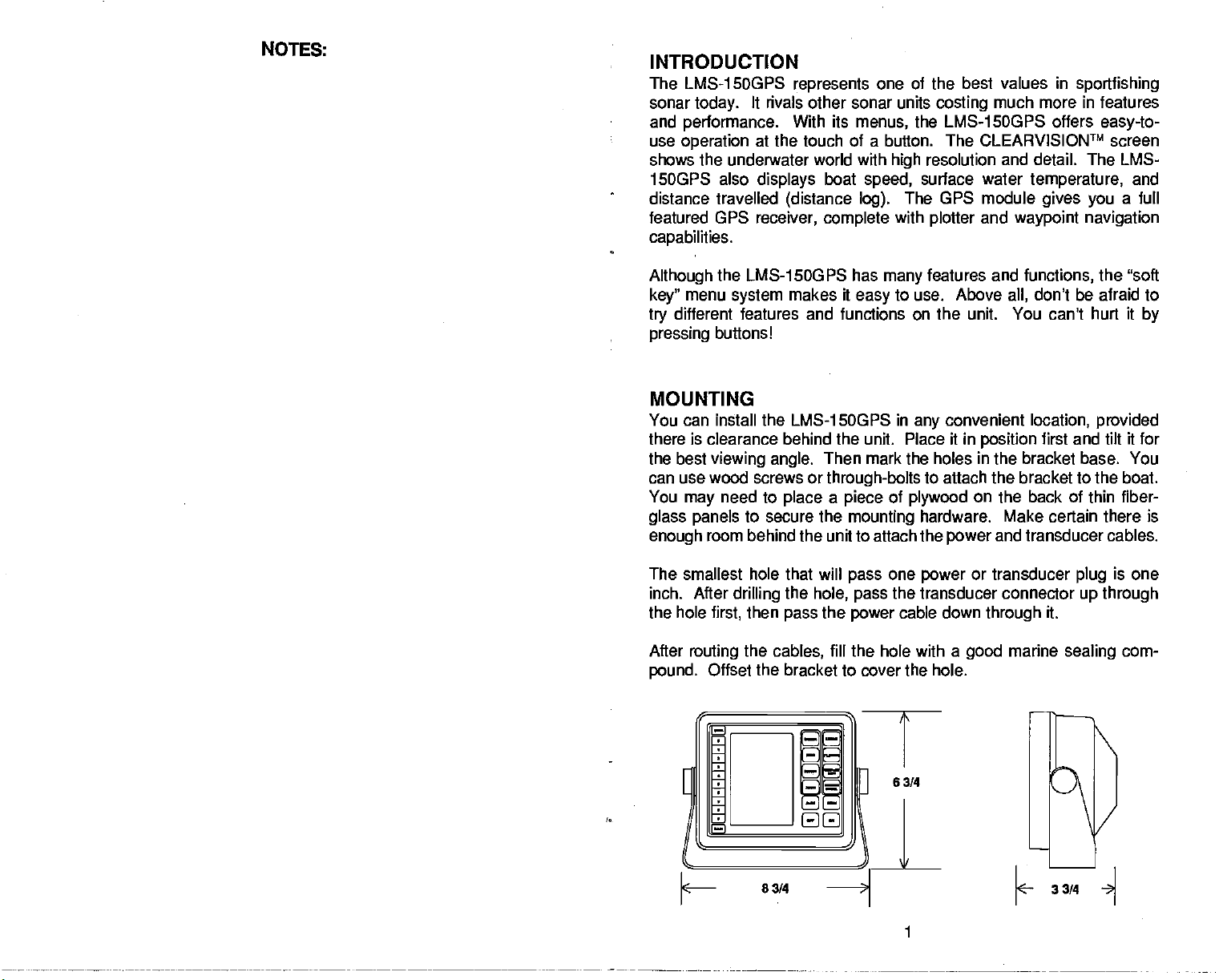
MOUNTING
You can install the LMS-1SOGPS in
there is clearance behind the unit. Place it in
the best
viewing angle.
can use wood screws or
You
glass
enough
need to
may
panels
to secure the
room behind the unit to attach the
The smallest hole that will
inch. After
the hole
After
pound.
drilling
then
first,
routing
the
cables,
Offset the bracket to cover the hole.
Then mark the holes
through-bolts
place a piece
mounting
one
the
pass
pass
hole,
pass
the
power
fill
the hole with a
of
the transducer
convenient
any
to attach the bracket to the boat.
plywood
hardware. Make certain there is
power
power
cable down
good
functions,
don't be afraid to
all,
location,
position
in
on
first and tilt it for
the bracket base. You
back of
the
and
transducer
or transducer
connector
through
it.
marine
the "soft
provided
thin
plug
up through
sealing
by
fiber-
cables.
is one
com-
33/4
1
PDF compression, OCR, web-optimization with CVISION's PdfCompressor
Page 6
POWER CONNECTIONS
The LMS-1 5OGPS works from a twelve-volt
best
results,
the
power
problems
attach the
enough, splice#1 8 gauge
red lead as close to the
have to extend the
end of the fuse holder
protect
attach the
cable to an
powercable directlytothe battery.
accessory
with electrical interference.
power
cable
directly
wire onto it. Attach the in-line fuse holderto the
power
cable to the
power
directly
both the
unit and the
power
or
power
Therefore,
to the
battery.
source as
battery
to the
battery
cable
possible.
battery system only.
You can attach
however
buss,
or
or
it's saferto
If
the cable
power buss,
power
you may
go
For
example,
buss. This
ahead and
is.
not
attach one
in the event of a short.
Forthe
have
long
if
you
will
NOTES:
The
powercable
black is
lead,
interface. To
autopilot
or other marine
the LMS-1 5OGPS's
hasthree
negative
wires, red, white,
or
ground.
usethisfeature,
equipment's
cable. Solder the twisted
power
and black.
The white wire is used for the
attach a
shielded,
NMEA interface to the white wire on
twisted
and shield wire to the black wire on the LMS-1 5OGPS's
not connect the shield wire to the
for more instructions. If
the white wire to
LMS-1
The
to the unit if the
work until the
Minimize electrical noise
possible
sources of electrical interference. One of the
generators
power
and transducer cables
Attach the
1
5OGPS's
speed/temperature
GPS MODULE
prevent
SOGPS has reverse
wires are hooked
power
is connected
wiring
is the
engine's wiring
speed/temp
powercable. Tags
sensor's connector.
INSTALLATION
not
you're
a short.
polarity protection.
by routing
away
sensor's and GPS
on the cables
autopilot.
going
properly.
harness.
from the
See
your
to use this
feature,
No
backwards. However,
up
the
power
cable
For
best
engine wiring.
module's cable to the LMS-
identify
both the GPS and the
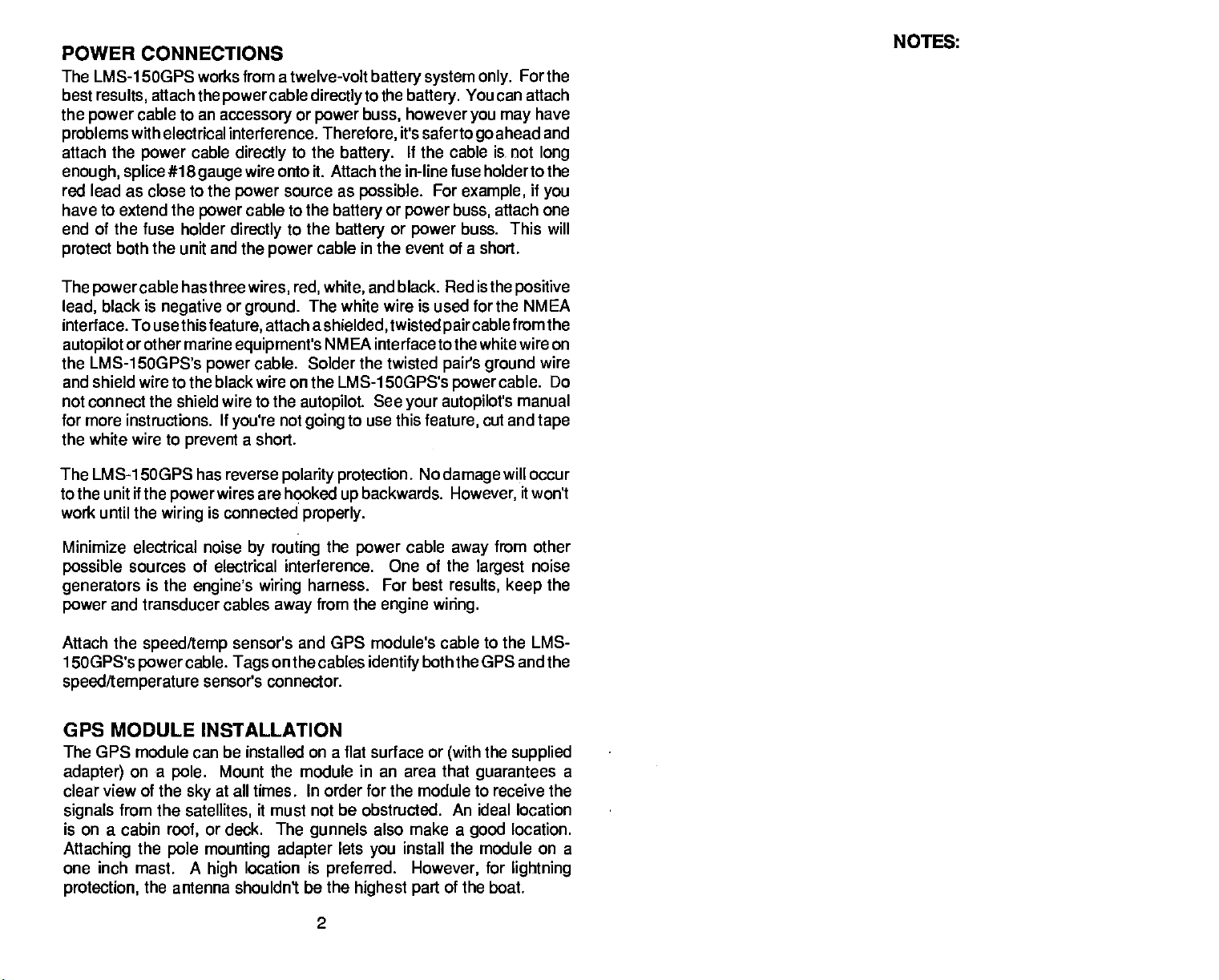
The GPS module can be installed on a flat surface or
adapter)
on a
pole.
clear view of the
signals
is on a cabin
Attaching
from the
roof,
the
pole mounting adapter
one inch mast. A
protection,
the antenna shouldn't be the
Mount the module in an area that
at all times. In order for the module to receive the
sky
satellites,
or deck. The
high
it must not be obstructed. An ideal location
gunnels
location is
also make a
lets
you
preferred.
highest part
install the module on a
However,
Red is the
paircable
positive
fromthe
pairs ground
cable. Do
power
autopilot's
manual
cut and
damage
will occur
it won't
from other
away
largest
results,
(with
keep
the
supplied
guarantees
location.
good
for
lightning
of the boat.
NMEA
wire
tape
noise
the
a
2
PDF compression, OCR, web-optimization with CVISION's PdfCompressor
Page 7
NOTES:
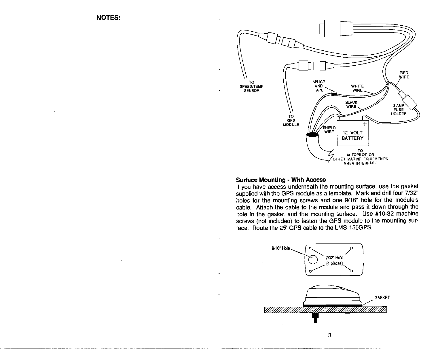
TO
SPEED/TEMP
SENSOR
TO
GPS
MODULE
TO
AUTOPILOT OR
OTHER MARINE EQUIPMENTS
NMEA INTERFACE
Surface
If
you
supplied
holes
cable. Attach
hole in the
screws
Mounting
have access underneath
with the GPS
for the
gasket
(not included)
-
With Access
the
mounting
module as a
mounting
screws and one 9/16" hole for the
template.
the cable to the module and
and the
mounting
surface. Use #10-32
to fasten the GPS module to
surface,
Mark and drill four 7/32"
use the
gasket
modules
pass
it down
the
through
machine
mounting
the
sur-
face. Route the 25' GPS cable to the LMS-15OGPS.
9/16' Hole
GASKET
PDF compression, OCR, web-optimization with CVISION's PdfCompressor
3
Page 8
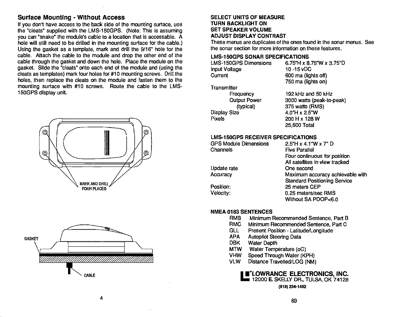
Surface
If
you
the 'cleats"
you
hole will
Using
cable. Attach the cable to the module and
cable
gasket.
cleats
holes,
mounting
1500PS
Mounting
don't have access to the back side of the
supplied
can "snake" the module's cable to a location that is accessable. A
still need
the
gasket
through
as
then
the
Slide the "cleats" onto each end of the module and
templates)
replace
surface with #10 screws.
display
unit.
-
Without Access
mounting
with the LMS-15OGPS.
to be
drilled
as a
template,
gasket
mark tour holes for #10
the cleats on the module and fasten them to the
in
the
mounting
mark and drill the 9/16"
and down the hole. Place the module on the
Route,
(Note:
surface for the
the other end of the
drop
mounting
the cable to the LMS-
surface,
This is
hole for
(using
screws. Drill the
use
assuming
cable.)
the.
the
SELECT UNITS OF MEASURE
TURN BACKLIGHT ON
SET SPEAKER VOLUME
ADJUST DISPLAY CONTRAST
These menus are
the sonar section for more information on these features.
LMS-1 50QP5 SONAR SPECIFICATIONS
LMS-1 5OGPS Dimensions 6.75"H x 8.75"W x 3.75"D
Input Voltage
Current 600 ma
Transmitter
Frequency
Output
Display
Pixels
LMS-1
GPS Module Dimensions 2.5"H x 4.1 "W x 7" 0
Channels Five Parallel
Update
Accuracy
Position: 25 meters CEP
Velocity:
Size
5OGPS RECEIVER SPECIFICATIONS
rate One second
duplicates
Power
(typical)
of the ones found in the sonar menus. See
10 -15 vDC
(lights off)
750 ma
192 kHz and 50 kHz
3000 watts
375 watts
4.0"H x 2.5"W
200
25,600
Four continuous for
All satellites in view tracked
Maximum
Standard
0.25 meters/sec RMS
Without SA PDOPc6.0
(lights on)
H x
128
Total
(peak-to-peak)
(RMS)
W
position
accuracy
Positioning
achievable with
Service
NMEA 0183 SENTENCES
GASKET
\
I
F
_// SS/S//
CABLE
4
RMB Minimum Recommended
RMC Minimum Recommended
GLL Present Position
APA
DBK Water
MTW Water
VHW
VLW Distance Travelled/LOG
Autopilot Steering
Depth
Temperature (oC)
Speed Through
•tLOwRANCE
12000 E SKELLY
-
Latitude/Longitude
Data
Water
(KPH)
ELECTRONICS,
DR., TULSA,
2341452
(91$)
69
Sentence,
Sentence,
(NM)
Part B
Part C
INC.
OK 74128
PDF compression, OCR, web-optimization with CVISION's PdfCompressor
Page 9
TIME FORMAT
The LMS-1 50's time format can be either 12
or
(AM
When the unit is first turned
preset,
change
then
key,
"CHANGE GPS SETUP" label. Now
the
key
"24 Hour Format ON" label
the
key
the time
a time
format,
now reads "12 Hour Format ON". Press the
next to that label for 12 hour format.
key
or 24 hour
PM)
(2:00 pm = 14:00).
or after it's
on,
the time format is 12 hour. To
to 24 hour
press
next to the "MORE" label until the
next to that label. The unit will show
in 24
display.
repeat
format, press
the
key adjacent
hour format on all screens with
To switch back to 12 hour
the above
steps.
the MENU
appears.
The menu
to the
press
Press
MAN OVERBOARD
Oneof
boating's mostterrifying
fall overboard. This situation can be
or salt, It's
Of
course,
measurestotry
can use the LMS-1 5OGPS to initiate a search
particularly dangerous
the first
thing
and rescuethe
events is
at
night
having
deadly
or if
on
todo is remain calm and
person.
If
you
CPS
Setup
Pg.2
ILr:Ii1I
l.
1r1!IiTas]
't—4N!
ii)
$u
a friend or
any body
you're
try
lose
sight
pattern.
family
of
water,
out of
sight
all standard
of the
person, you
.1
member
fresh
of land.
safety
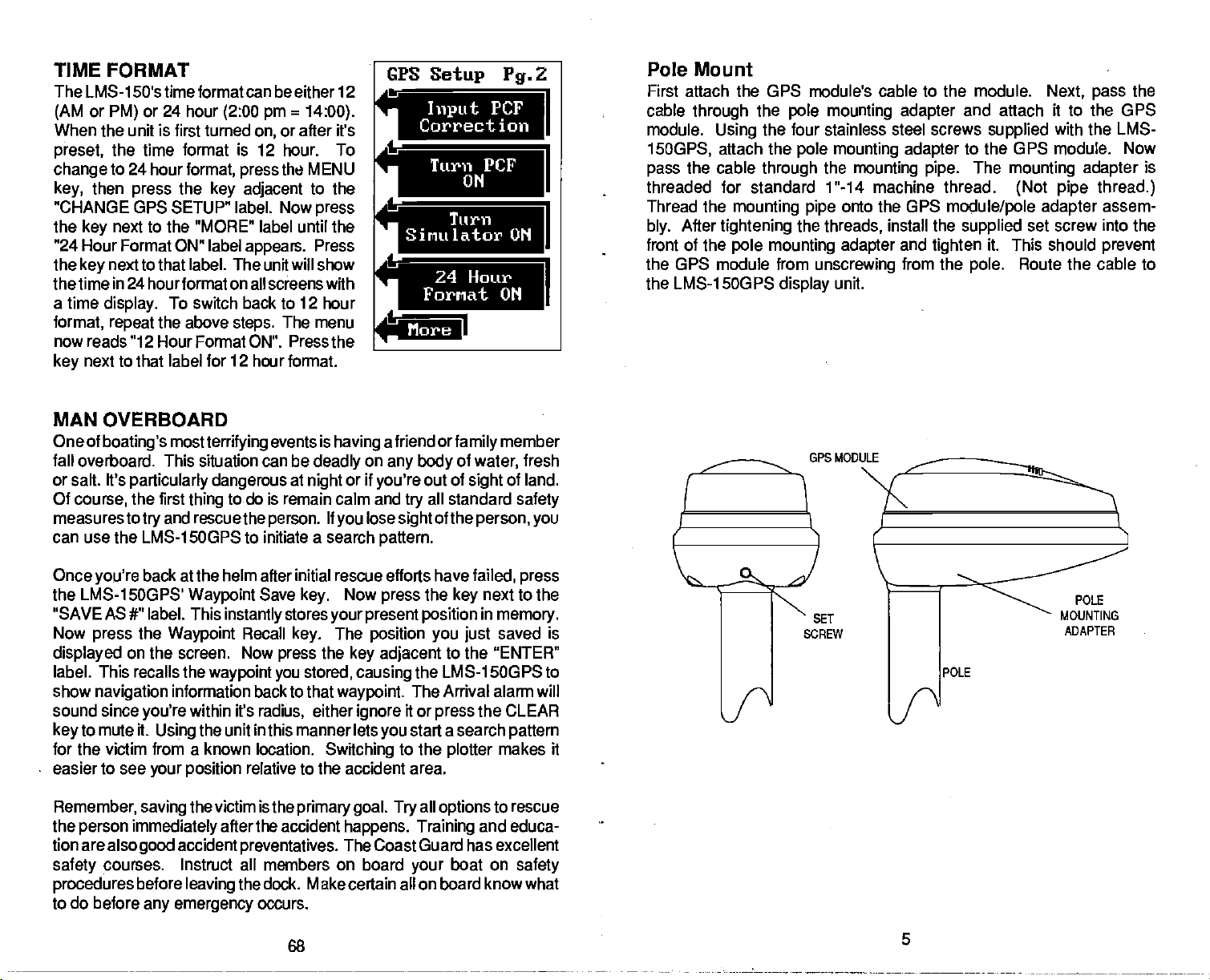
Pole Mount
First attach the GPS module's cable to the module.
cable
through
module.
15OGPS,
the cable
pass
threaded
Thread the
After
bly.
front of the
the
pole mounting adapter
the four stainless
Using
attach the
for
mounting
tightening
pole mounting adapter
pole
through
standard
the
the GPS module from
the LMS-15OGPS
display
steel screws
mounting adapter
the
mounting
1 "-14 machine thread.
onto the GPS
pipe
threads,
unscrewing
unit.
GPS MODULE
install the
and
from the
and attach it to the GPS
supplied
to
the GPS
The
pipe.
module/pole adapter
tighten
mounting adapter
(Not pipe thread.)
supplied
it. This should
pole.
Route the cable to
Next, pass
with the LMS-
module. Now
set screw into the
the
is
assem-
prevent
Once
you're
the LMS-1 5OGPS'
"SAVE AS
Now
press
displayed
label. This recalls the
show
sound since
to mute it.
key
for the victim from a known location.
easier to see
Remember,
the
person immediately
tion are
safety
procedures
to do before
PDF compression, OCR, web-optimization with CVISION's PdfCompressor
back at the helm after initial rescue efforts have
Waypoint
#" label. This
the
Waypoint
on
the screen. Now
waypoint you
navigation
alsogood
courses. Instruct all members on board
information back to that
within it's
you're
the unit in this manner lets
Using
your position
the victim is the
saving
accident
before
leaving
any emergency
Save
instantly
after the accident
stores
Recall
preventatives.
the dock. Make certain all on board know what
key.
press
radiUs,
relative to the accident area.
occurs.
68
Now
key.
your present position
the
stored,
either
Switching
primary goal. Try
press
The
position you just
key adjacent
causing
waypoint.
ignore
you
happens. Training
The Coast Guard has excellent
failed, press
the
next to the
key
in
to the
memory.
saved is
"ENTER"
the LMS-1 5OGPS to
The Arrival alarm will
it or
start a search
to the
all
your
the CLEAR
press
plotter
options
boat on
pattern
makes it
to rescue
and educa-
safety
POLE
MOUNTING
ADAPTER
POLE
Page 10
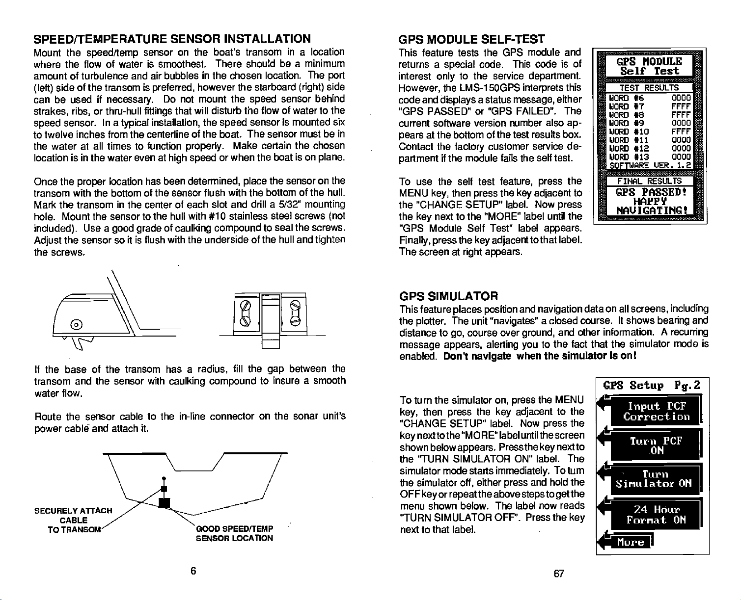
SPEED/TEMPERATURE SENSOR INSTALLATION
Mount the
where
speed/temp
the flow of water is smoothest. There should
amount of turbulence and air bubbles
side of the transom is
(left)
can be used if
strakes, ribs,
sensor. In a
speed
necessary.
or thru-hull
to twelve inches from the centerline
the water at all times to function
location
Once the
transom
is in the water even at
proper
location
with the bottom of the sensor flush with the bottom of the
sensor on the boat's transom
in
the chosen
however the starboard
the
will
that
disturb
the
speed
fittings
typical
preferred,
Do not mount
installation,
of the boat. The sensor must be in
properly.
high speed
has been
determined,
or when the boat is on
speed
the flow of water to the
sensor is mounted six
Make certain the chosen
place
Mark the transom in the center of each slot and drill a 5/321!
Mount the sensor to the hull with #10 stainless
hole.
included).
Adjust
the sensor so it is flush with the underside of the hull and
Use a
good grade
of
caulking
compound
in
a location
be a minimum
location. The
(right)
sensor behind
the sensor on the
steel screws
seal the screws.
to
the screws.
If the base of the transom has a
transom and the sensor with
caulking compound
radius,
fill the
water flow.
Route the sensor cable to the in-line connector
cable7 and attach it.
power
SECURELY
CABLE
TO
GOOD SPEEDITEMP
SENSOR LOCATION
on the sonar unit's
between the
gap
to insure a smooth
port
side
plane.
hull.
mounting
(not
tighten
GPS MODULE
SELF-TEST
This feature tests the GPS module and
returns a
interest
only
However,
code and
special
the LMS-15OGPS
displays
code. This code is of
to the service
a status
department.
interprets
message,
this
either
"GPS PASSED" or "GPS FAILED". The
current software version number also
at the bottom of the test results
pears
Contact the
partment
factory
if the module fails the
To use the self test
MENU
key,
then
customer service de-
self test.
feature, press
the
press
key adjacent
the "CHANGE SETUP" label. Now
the
"GPS Module Self Test" label
Finally, press
The screen at
next to the "MORE" label until the
key
the
key adjacent
right appears.
tothat label.
ap-
box.
the
to
press
appears.
GPS SIMULATOR
This feature
the
plotter.
distance to
message appears,
enabled. Don't
places position
The unit
course over
go,
alerting you
navigate
To turn the simulator
then
key,
"CHANGE SETUP" label. Now
nexttothe "MORE" label until thescreen
key
shown
belowappears. Pressthekeynextto
press
the
the 'TURN SIMULATOR ON" label. The
simulator mode starts
the simulator
OFF
menu shown below. The label now
"TURN SIMULATOR OFF". Press the
next to that label.
key
or
either
oft,
repeatthe
and
navigation
"navigates"
a closed course. It shows
ground,
and other information.
to the fact that the simulator mode is
when the simulator is on!
on,
key adjacent
immediately.
press
above
the MENU
press
press
and hold the
steps
to the
To turn
to
get
reads
the
the
key
CPS MODULE
Self Test
TEST RESULTS
WORD #6 U000
WORD #7
WORD #8 rrrr
WORD #9 0000
WORD #10 vrrr
WORD #11
WORD #12 0000
WORD #13
SOFTWARE
FIHAL RESULTS
GPS PASSED!
HAPPY
NAU IGAT
data on all
screens, including
More
FFFF
0000
0000
tiER. 1.2
INGt
bearing
A
recurring
and
PDF compression, OCR, web-optimization with CVISION's PdfCompressor
6
67
Page 11
NMEA COMMUNICATION
The LMS-15OGPS sends
according
(National
This allows the LMS-1 5OGPS to send
tion, depth,
"listener'
ments,
ments. The LMS-1 500PS uses
NMEA data
ing
0183.
.tion
NMEA 0183 sends
ing, speed,
feature,
must
on the other
tion section for
tion.
Once the
which data format to use. Consult
equipment
as follows:
First,
Next,
adjacent
appears.
appears.
The data format
key adjacent
to standards set
Marine Electronics
and
navigation
such as
units,
autopilots,
NMEA
It's useful
only.
and other marine instru-
protocols:
sends
0180
and more.
the white wire on the
be connected to the NM EA data
instrument. See the installa-
wiring
is connected
wiring
to see the which format
MENU
the
press
press
the
next to the
key
to the"More" label until
Press the
currently
to the desired data
the last used GPS or
PRESET
The Preset feature returns all sonar and
settings.
mode on the sonar
any waypoints
all
navigation
This resets the units of
side,
or
routes,
to a
waypoint
data out the white wire on the
the NMEA
by
Association).
information to
charting
NMEA 0180 and
steering
mainly
depth,
for
position,
In order to use this
connection informa-
instrti-
the follow-
informa-
autopilots.
steer-
cable
power
properly,
the owner's manual of the "listener"
ft needs. Then set the LMS-1 SOGPS
while a GPS or
key
'Change Setup"
the "SELECT NMEA ouTPUT" label
next to this
key
in
shows at the
use
output.
screen,
plotter
display
however. The GPS
or route
and send
measure, speaker
contrast,
will
power
posi-
input
LMS-1 5OGPS must be told
the
plotter
label. The screen shown above
top
The LMS-1 SOGPS will return to
GPS units to their
and more. This doesn't erase
will
be cancelled.
screen is
label. Now
of the screen. Press the
NMEA data out the white
haveto
press
original factory
volume,
be initialized and
cable
displayed.
the
key
automatic
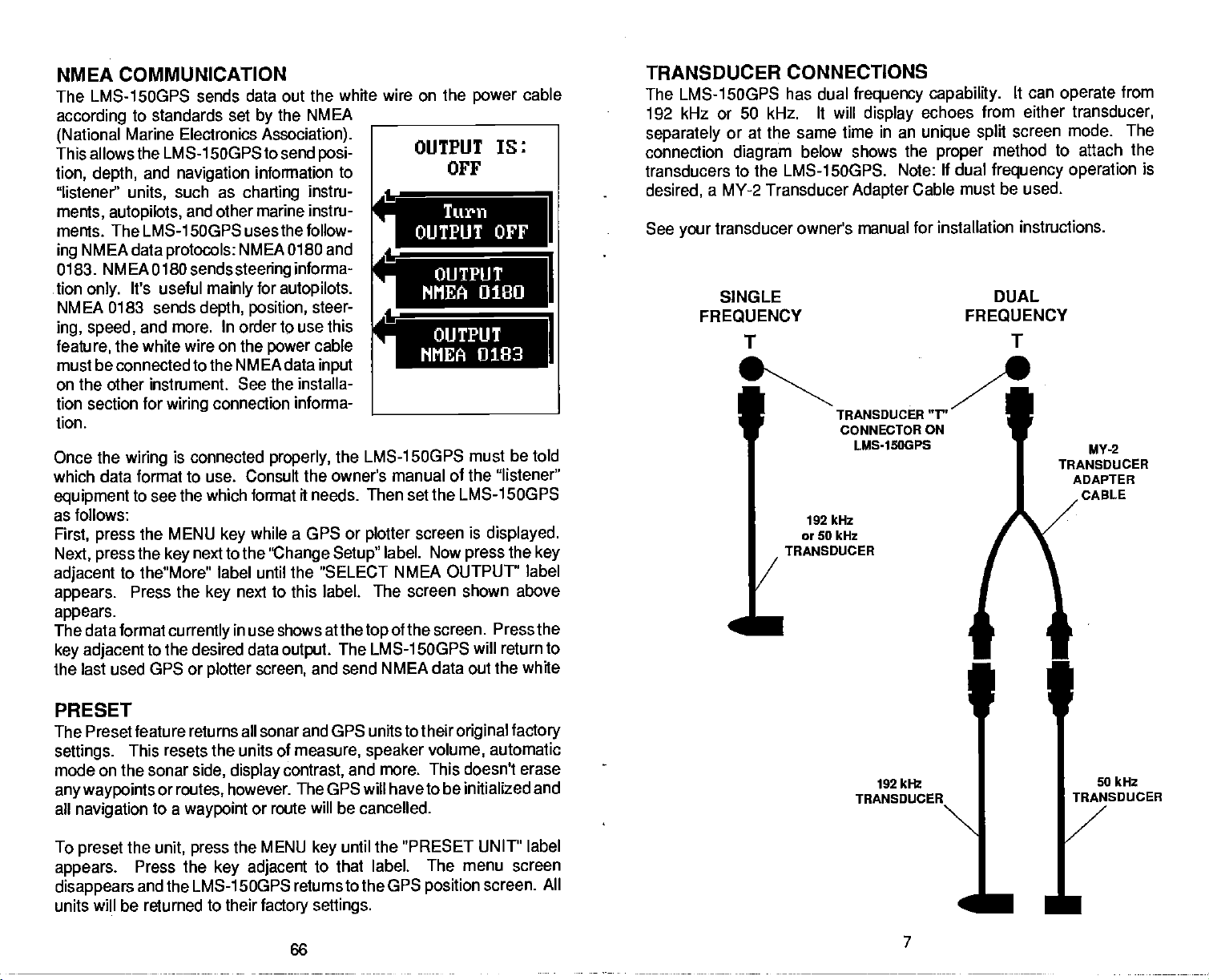
TRANSDUCER
LMS-15OGPS has dual
The
192 kHz or
separately
connection
transducers
desired,
See
your
50 kHz. It will
or at the same time in an
diagram
to the LMS-1 5OGPS. Note:
a MY-2 Transducer
transducer owner's manual for installation
SINGLE
FREQUENCY
T
/
I
CONNECTIONS
frequency capability.
display
below shows the
Adapter
TRANSDUCER
CONNECTOR ON
LMS-1SOGPS
192 kHz
or 50 kHz
TRANSDUCER
TRANSDUCER
Cable
192 kHz
can
It
operate
echoes from either transducer,
unique split
proper
If
method
dual
frequency operation
must be used.
DUAL
FREQUENCY
screen
mode. The
to attach the
instructions.
from
is
T
"V'
MY-2
TRANSDUCER
ADAPTER
CABLE
p
I
50 kIlz
To
preset
appears.
disappears
units will be returned to their
PDF compression, OCR, web-optimization with CVISION's PdfCompressor
the
unit,
Press the
and the LMS-1 SOGPS returns to the GPS
the MENU
press
key adjacent
until the
key
to that label. The menu
factory settings.
66
"PRESET UNIT" label
screen
position
screen. All
I
—
7
Page 12
will add the
match the datum used
0
AUTOS
50.
11
[SONAR1
[ Il
when
change
change you
entering
when the unit is turned off.
the PCF Offset. This is saved in
made to all
chart. Forthis
bythe
positions.
reason,
This makes it more
should be careful
you
memory.
It does not
closely
2
3
4
5
6
7
d
s—.
8
9
—w
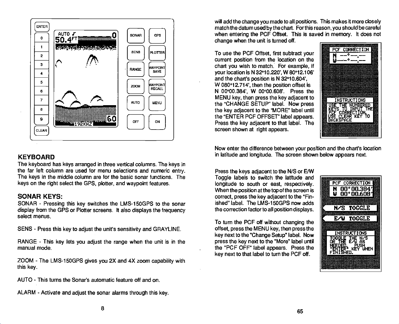
KEYBOARD
The
keyboard
the far left column
The
keys
on the
keys
SONAR KEYS:
SONAR
display
select menus.
SEWS
RANGE - This
manual mode.
ZOOM
this
from the GPS or Plotter screens. It also
-
-
key.
has
in the middle column are for the basic
select the
right
-
Pressing
Press this
key
The LMS-1 5OGPS
SENS
[
]
[PLoA]
cAYPOI
[NeE]
[zMD
/ja
192KHZ
keys arranged
are used for menu selections and numeric
this
key
to
key
adjust
lets
you adjust
—'
/
[AUTO ]
[OFF I
in
three vertical columns. The
sonar functions. The
GPS, plotter,
switches the LMS-1500PS to the sonar
the unit's
gives you
and
sensitivity
the
range
2X and 4X
waypoint
displays
when the unit is in the
SAVE
L
c;AVPOIN1;
LRECALLJ
[MENU I
H
features.
the
and GRAYLINE.
zoom
capability
in
keys
entry.
frequency
with
To use the PCF
current
chart
your
and the chart's
W
N
MENU
the "CHANGE SETUP" label. Now
the
the
Press the
screen shown at
Now enter the difference between
in latitude
Press the
Toggle
longitude
When the
correct,
ished" label. The LMS-1 5OGPS now adds
the correction factorto all
To turn the PCF off without
offset,
key
press
the "PCF OFF" label
key
position
wish to match: For
you
location is N 32°1
080012.714',
00°00.384',
key,
key adjacent
"ENTER
keys adjacent
labels to switch the latitude and
position
press
press
next to the
the
key
next to that label to turn the PCF off.
Offset,
from the location on the
position
then the
W 00°00.608'. Press the
then
press
to the "MORE" label until
PCF OFFSET" label
key adjacent
and
longitude.
to south or
the
the MENU
"Change Setup"
next to the "More" label until
first subtract
0.220',
right appears.
at the
key adjacent
appears.
W 80012.106'
is N 32°1
position
the
key adjacent
to that label. The
The screen shown below
to the N/S or E/W
east,
respectively.
of the screen is
top
position displays.
changing
then
key,
your
example,
0.604',
offset is
to
press
appears.
your position
to the "Fin-
the
the
press
label. Now
Press the
if
and the chart's location
appears
Pcr coRREcTIoN
N 00000.384
U OO°OO.608'
next.
I
N/S TOGGLE
r
E/W TOGGLE
IHSTRIXTIONS
HEEDED. PUSH
"EWER KEY WHEN
FINISHED.
ib
AUTO - This
ALARM
turns the Sonar's automatic feature off and on.
-
Activate and
the sonar alarms
adjust
through
8
this
key.
PDF compression, OCR, web-optimization with CVISION's PdfCompressor
Page 13

GDOP stands for Geometric Dilution Of Pre-
cision. This is a
shows the combination value of horizontal
(HDOP),
The
the
selects satellites based on
it
always
in
GDOP is to
other
creasing,
out of
system may
lites don't
The HDOP
smaller the number
is
page.
time and UTC time
PCF
vertical
smaller the GUOP number
crossing angles
tries to use satellites that will result
good crossing angles.
words,
then the satellites could be
your viewing range. Therefore,
5-10
good,
The UTC OFFSET is the numberof hours difference between
OFFSET
(Position
The GPS
to determine
factor is the Earth's
navigation system
crossing angle
(VDOP),
are. The GPS receiver
The best
anticipate system
if the
crossing
become unusable if more satel-
appear shortly.
is
fair,
shows the
the better
is,
and
anything
(GMT)
display
Correction
your position
shape.
indicator. It
and
Time
(TDOP).
the better
is,
GDOP,
in
therefore
use
wayto
problems.
angles
horizontal
2D,
the
over lOis
Greenwich, England.
In
are de-
moving
the
crossing angles
Engineering
HDOP 001.69
GDOP 003.87
UDOP 002.87
PDOP 003.33
TDOP 001.98
UTC OFFSET
crossing angle. Again,
for all
poor
Factor)
relies on
based on
Since the Earth is not a true
complex
satellite
mathematical calculations
data and other factors. One
Screen
+
E
are.
Typically,
displays
sphere,
5 :130
U
the
1-4
on this
your
variations
in the calculations haveto be madeto accommodate deviations. To make
matters more
what the deviations are. The size
to
approximate
errors if
your
complex,
the earth's surface are
navigation
a different one. The term used for these
To reduce the error factor between
the
capability
match one shown on the chart. The unit adds this offset to all
displays.
For
example, suppose you
marked on a chart. Your LMS-1 5OGPS
is .010
Correction Factor
the same as the chart. If
to move or "offset" the
degrees
not
everyone
device
are anchored at a location that is
less than the one on the chart.
Offset
(PCF)
feature,
raise anchor and
you
uses the same data to determine
and
uses one
datum,
of
shape
the
improved
ellipsoid,
ellipsoids
often. This can lead to
the LMS-15OGPS
position
displays a longitude position
you
shown on the
makethe LMS-1 5OGPS read
move,
your
Using
that are used
chart uses
gives you
display
accurately
the Position
ellipsoids
while
is "datum."
the LMS-1 5OGPS
to
position
that
GPS KEYS:
-
GPS
WAYPOINT
WAYPOINT RECALL
Press this
PLOTTER
-
This
SAVE
to switch to the
key
switches the LMS-1 5OGPS to the
key
-
Press this
-
This
key
activates the
key
OTHER KEYS:
ENTER
CLEAR - Use this
ON
OFF - The Off
MENU
three modes
MENU
appears. Pressing
up
DISPLAY
The
15OGPS on. Menus
press
page.)
If
cally
turn them off at
The Metric menu works the same
Metric label to
the
nautical miles.
-
This
-
The ON
NOTE. You must
KEY
while the sonar screen is
key
is
used to enter selections from menus.
key
to erase a
key
turns the LMS-15OGPS on.
key
turns the LMS-1SOGPS off.
key
press
-
This
key
-
sonar, GPS,
the MENU
the first
you
temperature display
plotter
are on for about ten
lights
the
key adjacent
It controls the
don't want the
turn off. The menus also
menu screen.
-
General
any
change
appear
backlighting
lights on,
time
the
and hold
activates the first menu screen for each of the
and
plotter.
key
seconds when
at the same time. To
to the
Light
wait ten seconds and the
disappear
by pressing
from
depth
to
degrees Celsius,
GPS
displays.
to save
previous keystroke
the OFF
while the
label.
used on the
way.
waypoints.
waypoint
or menu.
to turn the unit off.
key
For
example,
displayed,
(See
after ten seconds. You can
the CLEAR
Press the
feet to meters. This also
the first sonar menu
plotter
speed
is
first turn the LMS-
you
keep
the
picture
display
key.
key adjacent
to
plotter display.
recall menus.
if
you press
displayed brings
the
lights
the
on,
on the next
and
keyboard.
automati-
lights
to the
changes
knots,
and
log
to
PDF compression, OCR, web-optimization with CVISION's PdfCompressor
64
9
Page 14

The ADJ
viewing angle. Pressing
See the
After the menus
next
cates the automatic feature is on.
"AUTO" indicator means the alarm
bottom
Display
Display
page.
depth displays immediately
label lets
Contrast section for more
clear,
The word "AUTO"
0
2
3
4
5
S
7
8
9
you adjust
this
key gives you
the
display appears
in the
MEMORY-PRESET
The LMS-1SOGPS
alarm
settings,
is
retained,
To erase the
settings,
press
the
starting beep,
the
factory
routes.
See the Menu
information.
To turn the
even if the LMS-1 5OGPS is
turn the unit
ON
the
default
There is also a menu selection
battery-backup
saves all
and more in
settings,
at the same time.
key
-
Page
and return
off,
then release it.
settings.
7 "Preset SONAR
settings
battery
then
press
Note: This doesn't
feature
the
display's
information on this feature.
display's upper
A small note
speaker
beneath the AUTO indicator.
io
contrast for the best
the contrast
similar to the one
is enabled. The
adjust
left corner
symbol
next to the
H
H
H
H
WAYPOINT
SAVE
WAYPONT
RECALL
on the
H
H
such as
backed-up memory.
removed from the boat.
the LMS-15OGPS to the
and
Hold the CLEAR
The LMS-15OGPS will restart
see
off,
sensitivity,
hold the CLEAR
erase
that resets the LMS-15OGPS.
& GPS" on
page
H
key
any waypoints
page
37.
chart
This
memory
key
until
you
40 for more
menu.
indi-
digital
speed,
factory
and
hear
using
or
SATELLITE INFORMATION
SCREEN
The Satellite Information
nical data about
range.
LMS-1500PS
satellite
press
until the
bel
label. The screen shown at
This screen shows the
tion:presentposition,
ber
(AZM),
(SN),
The LMS-1 SOGPS has a
appears
The satellite number
channel number.
location. Elevation
the
has three
channel is not
the
appears.
example
searching.
Beneath the Satellite Info
from
Up
data, press
the
"SATELLITE INFORMATION" la-
appears.
(C),
elevation
channel
signal-to-noise
displays
your
each satellite in the
to 5 satellites can be used
at one time. To view the
key adjacent
Press the
satellite number
status(T),
at the
display's
possible
using
for that channel. If it is
Once it's locked on to the
screen on this
location.
ENGINEERING SCREEN
The LMS-1 SOGPS
(HDOP),
(TDOP).
To view this
"More" label until
adjacent
appears
geometric (GDOP).,
These are
screen, press
to that label.
screen showstech-
the MENU
key,
to the "More" label
key adjacent
right appears.
following
receiverchannelnum-
(SAT),
(EL), signal-to-noise
and visible
five-channel receiver. The channel number
left in the "CHANNEL INFO"
in use
(SAT)
Azimuth isthedirection of the satellitefrom
is
the
height
ratio. The
modes: Idle
a
satellite,
page
display
are listed
They
lets
you
displayed
the
"Engineering
The screen shown at the
by
of the satellite above
higher
(-), Searching(S),
then it is idle and
has channels
viewthe Dilution of Precision forthe
vertical
on
MENU
the
IOH
3r09.064'
ti
95°50450'
viewing
by
then
to that
informa-
azimuth
ratio
satellites.
the channel shows
the
searching
satellite,
is the
their satellite number.
by
(VOOP), position (PDOP),
the
Engineering
key
Screen" label
u
the
tëHANNEL
the
SN,
for the
then the
1,3,4
list of satellites that are visable
,then
press
-p -U -U !!
Iu• 1a ,—
13
311
12
324
02 115 46 43
208 28 42
74 1935
VISIBLE
13 02 06 24
12 14
box.
to the
the horizon. SN is
better. Channel status
or
Tracking (T).
dashed lines
satellite,
(T) appears.
and 5
Screen.
the
key
appears.
of the next
top
INFO
60
35
27
29 T 8
1
I
1
SATS
of the
right
yourpresent
If the
appear
the
(5)
The
tracking,
Press the
3 is
horizontal
time
and
next to the
key
page
in
PDF compression, OCR, web-optimization with CVISION's PdfCompressor
10
63
Page 15

GPS ALARMS
The LMS-1500PS has two OPS alarms. One is an arrival alarm that
sounds
is a C.D.I. alarm that sounds when
alarm's
when
setting.
come within a
you
preset
you
distance to a
off course more than the
move
waypoint.
The other
ARRIVAL ALARM
The arrival alarm sounds a tone when
radius of a
.1 nautical mile of a recalled
arrival alarm's
adjustable
To
adjustthe
key,
ALARMS label. The screen shown at
appears.
on for the first
preset
arrival alarm
to the
radius, press
arrow.
"ARRIVAL OFF" label turns it off.
waypoint.
setting
from zero to 9.99 miles.
arrival
then
press
When the LMS-1 SOGPS is turned
.1
to
nautical
radius, press
arrow. To decrease the alarm
up
the
Pressing
For
example,
waypoint
is .1 nautical mile. It's
alarm,
pressthe
the
key adjacenttothe
the arrival alarm is
time,
mile.
To increase the
the
key adjadent
the
key adjacent
the alarm sounds
MENU
key adjacent
to the down
to the
your position
if
the
GPS
right
within the alarm's
is
if
you
'S
ARRIVAL ALEM
—
S
u. MI
Arri ual Off
XTE ALARM
come
within
0.2 iii
—;jj--;j- pnOff
I
Press the CLEAR
menu.
XTE ALARM and RANGE
Changing
screen. To
Then
appears.
The
key adjacent
alarm. The alarm is
The XTE Alarm sounds a tone when
the alarm
nautical mile.
mile,
the XTE alarm also
change
the
press
XTE
alarm
key adjacent
adjustment
to the
setting.
If
you
the XTE alarm sounds an alert tone.
to exit the alarm
key
XTE
the
or down arrow to increase or decrease the XTE
up
adjustable
For
example,
move to the left of course
changes
alarm
to the "GPS ALARMS' label.
menu is
from 0.1 to 9.9 miles.
the XTE
settings,
in
the middle of the screen.
your
suppose
first
cross track error is more than
the XTE alarm is set to 0.1
by
range
press
more
on the
the
MENU
This screen
0.1 nautical
than
Press the
steering
key.
FREQUENCY
Lowrance offers both 50 and 192 kHz transducers for the LMS-1 5OGPS.
The 192
fish, structure,
192 kHz doesn't
go
50s. You can draw a few conclusions from these statements.
1. Use 192 kHz
cone
narrow cone
deep depths.
2. Use the 50 kHz in
desired.
see the
both a 30
The LMS-1 500PS has the
operate
display
both at the same time in an
screen mode. Once the transducers are
connected to
Transducer Connections section for more
information),
kHz
as
deep. Also,
angle
Using
downrigger weights display
degree
at 192 kHz or 50 kHz. It can
echoes from either transducer or
the SONAR
one shown at
Press the
quency
kHz
50
from both transducers at the same time.
Anytime you
This will cause the
disappear
erase them.
key adjacent
or
& 192
SELECT
frequency typically
and bottom definition better than 50 kkz.
penetrate
192 kHz cone
(especially
for the best resolution and
transducer
angle
deep
50 kHz when
has
superior target resolution, showing
water as well as 50
angles
in shallow
(8 degree)
water or where a
fishing
are
typically
water)
target
with
with a wide
definition. Use a 192 kHz
when
very
downriggers generally
on the screen. Lowrance offers
and 45
degree
cone
capability
angles
to ____________
for 50 kI-lz.
AuTo J'
raffic
unique split-
the LMS-1 5OGPS
turn the unit on and
A
key.
screen similar to
right appears.
to the desired fre-
the
press
kHz
wish to switch
after a few seconds or
key adjacent
label to
display
frequencies, simply press
frequency
the
(see
press
the
to the
echoes
switch menus to
can
you
press
However,
therefore it won't
kHz,
narrower than the
(20 degree)
operating
in medium
wide cone
192KHZ
the SONAR
appear. They
the CLEAR
the
angle
lets
you
key.
will
key
0
to
to
is
After
you've
finished with the
settings
on this
page. press
the
CLEAR
key
to return to the OPS screen.
PDF compression, OCR, web-optimization with CVISION's PdfCompressor
62
11
Page 16

AUTOMATIC
When the LMS-15OGPS is first turned
This is shown
Automatic feature
always
To turn Automatic
UAL"
Automatic
shows in the lower half of the screen.
appears,
on,
AUTOMATIC
MODE ON
the word "AUTO" at the
by
adjusts
the
sensitivity
off, simply press
AUTO
the
AUTOS
50.
the unit is
key
3
showing
press
the
again.
Th
r\r
the Automatic feature is on.
on,
of the screen.
top
and
AUTO
in
the
so the bottom
range
key.
manual
The word "MAN-
mode. To turn
n
The
signal
ERASING
To erase a
the "ROUTES" label
the
key
tion screen shown on the
appears.
"Inc RTE#" or "Dec RTE#" arrows to view
A
ROUTE
route,
press
next to that
Press the
the MENU
appears,
label. The route selec-
previous page
keys adjacent
key
then
until
press
to the
a different route number. When the desired
route shows on the
TER
right appears.
press
ROUTE' label. The LMS-15OGPS returns
The route menu screen shown at
key.
the
key adjacent
to the last used GPS or
route is now erased.
display, press
To erase the selected
to the
plotter
the EN-
route,
"ERASE A
display.
The
Route
Add to
Menu
A
Route
I
Follow A
Route
I
Route Bckward
4
Forward
Follow A
Erase A
Route
SENSITIVITY
The
sensitivity
pick up
information,
levels enables
with noise.
bottom
The LMS-1 5OGPS
mode. This
show fish and other detail.
However,
decrease the
more detail. The
echoes.
fish
Typically,
signal
keeps
situations occur where it becomes
on the LMS-1
key
A low
sensitivity
signals,
to see this
you
with GRAYLINE® and some surface clutter.
the best
adjusts
a solid bottom
sensitivity.
procedure
and other
This
5OGPS controls the unit's
level excludes much of the bottom
information.
target
but it can also clutter thO screen
detail,
sensitivity
the
sensitivity
signal displayed, plus
typically happens
to
adjust
level shows a
when it's in the automatic
necessary
it is the same whether the unit is
when
High sensitivity
good
the
capability
to increase
wish to see
you
in the automatic or manual mode.
PDF compression, OCR, web-optimization with CVISION's PdfCompressor
12
ability
solid
to
to
or
CANCEL NAVIGATION
To
on a route or to a
Navigation
the MENU
TION" label
adjacent
immediately stops
mation to the
route,
erase the
the LMS-1 5OGPS
stop
feature. To do
untilthe
key
appears.
to that label. The LMS-1 5OGPS
waypoint.
if it was in use.
waypoint
waypoint,
showing navigation
or route.
from
this, simply press
"CANCEL NAVIGA-
Now
It also cancels the
However,
navigating
use the Cancel
the
press
key
infor-
it doesn't
61
CPS Menu
Engineering
h
a
Screen
Preset
A
Turn
Bachup
More
—
Pg.3
tJnit
Battery
Off
J
Page 17

As each
number in the box near the
have
memory.
waypoint
been
selected, press
is
selected,
ft's number
of the screen. After all of the
top
the CLEAR
key.
FOLLOWING A ROUTE
To follow a
then
press
route,
the
key
right appears.
Waypoints
stored in the route show in the box
route number. Press the
arrows to view a different route number.
the ENTER
press
page appears.
To travel forward
from the first
press
FORWARD" label. To travel backward
through
the
the
waypoint
next tothe "FOLLOW ROUTE
key
route,
the MENU
press
key
next to that label. The
The route number
keys adjacent
The route menu
key.
through
the route
on the list tothe
the
press
key adjacent
until the "ROUTES"
route selection menu shown at
appears
to the
When the desired route
screen shown on the
(i.e.,
last),
to
the "FOLLOW ROUTE BACKWRD" label.
The screen shown below
select the
waypoint
travel to
However,
in the middle of the
adjacent
arrows to move
ROUTE *01
EIN
starting waypoint.
on the list is the one
first,
simply press
if
wish to start with
you
route, press
to the "Inc WPT#" or "Dec WPT#"
through
I
03 12 18
,
Inc IIIPTII
Dec UPTU
WPT *18 OK
N 36°1O.324'
95°50.022'
INSTRUCTIONS
"ENTER" TO
PRESS
BEGIN NAI,JXGATIHG
I
appears.
you
the ENTER
the
waypoint
When the box surrounds the desired start-
ing waypoint
press
returns
screen
waypoint
that
cally
route.
all of the
Now
If the first
wish to
key.
awaypoint
the
key
list.
the ENTER
to the last used GPS or
showing navigation
in the route. After
waypoint,
switches to the next
This
repeats
waypoints
appears
This stores
at the
immediately
beneath
top
the route
waypoints
route
your
label
appears,
of the screen.
beneath the
"Inc RTE#" or "Dec RTE#"
shows,
opposite
*01
ROUTE
00 03 12 18
Inc RTEIt
Dec WEE It
INSTRUCTIONS
USE INC/DEC RTE
KEYS TO SELECT
THE DESIRED
ROUTE.
PUSH "ENTER" TO
SELECT ROUTE,
near the
key.
the LMS-1 500PS automati-
until
in the route.
top
of the
screen,
The LMS-1 5OGPS
plotter
data to the first
arrive at
you
waypoint
you've
in the
travelled to
in
To
adjust
menu
menu is
The
graph.
number above
the
appears
immediately
sensitivity
The
46.7FT
SELlS
.
B?
sensitivity, press
the SENS
on the left side of the screen.
beneath it.
menu has
graph gives
the
arrow shows the
up
and down
up
an indication of the
percentage
A
The
key.
sensitivity adjust
The GRAYLINE®
arrows,
plus
sensitivity
of
sensitivity
adjust
a vertical bar
level. The
in use.
60
192KHZ
sENsITIvITY ADJUST MENU
(Single Frequency)
To increase the
arrow on the left side of the unit. As
up
bar
graph
will
sensitivity
taller and the
grow
level,
press
percentage
can also see the difference on the chart record as it scrolls. When the
sensitivity
To decrease the
arrow. The bar
tivity
When
sound an alert tone.
is at the desired
sensitivity
graph
is at the desired
reach either the maximum or minimum
you
To turn the menus
and
level,
off, press
release the
level,
level,
press
percentage
release the
the
key adjacent
bottom left side of the unit.
When
menu
appears
both
frequencies. Simply press
label to
the LMS-15OGPS
using
that lets
each side.
adjust
you
in the dual
the
adjust
the
key adjacent
SENSI11VITY ADJUST MENU
(Dual Frequency)
the
key adjacent
you press
the
key,
will increase
key.
the
key adjacent
will
decrease.
key.
When the sensi-
the
limit,
to the CLEAR
frequency
sensitivity
and GRAYLINE for
to the 50kHz/i 92 kHz
to the menu's
the menu's
in
value.
You
to the down
key
will
at the
a new
speaker
mode,
60
13 PDF compression, OCR, web-optimization with CVISION's PdfCompressor
Page 18

GRAVLINE
GRAYLINE
"paints"
allows
example,
displays
which causes a wide
signal
If
you
without,
weeds from trees on the
guish
GRAYLINE® is
between
a
different GRAYLINE®
1
500PS at
ment with
lets
you distinguish
on
gray
you
a
with a narrow or no
have two
the
strong
your
targets
to tell the difference between a hard and soft bottom. For
soft, muddy
signals
target
adjustable.
and weak
power
unit to find the GRAYLINE
46.7FT
SEWS
___
that are
or
weedy
gray
gray
of
equal size,
with
gray
Since GRAYLINE® shows the difference
signals, adjusting
level,
on is
usually adequate
A
between
stronger
bottom returns a weaker
line. A hard bottom returns a
line.
is the
bottom,
also. The level chosen
strong
one with
stronger signal.
or fish from structure.
and weak echoes.
than a
preset
gray
This
the
sensitivity may require
for most conditions.
setting
that's best
It
value. This
which
signal
strong
and the other
distin-
helps
LMS-
the
by
Experi-
for
you.
arrows until the desired route number
at the
pears
waypoints
beneath the route number. Once the
pear
desired route number
the
screen,
screen shown at
the
label. The screen shown below
next to the "ADD TO A ROUTE'
key
ROUTE *01
of
the screen.
top
stored in the
displays
the ENTER
press
right appears.
If
there are
route, they
at the
key.
Now
appears.
will
top
press
NO
UPTE IN
ROUTE
__________________
r
Inc UFTU
___________________
Dec WFTU
LIJPT #00 OK
N 360 09,064'
w 950 50,450'
__________________
INSTRUCTIOHS
PUSH "ENTER" TO
This is the
lets
placed
-
number and location
choose which
you
in
of the screen. Use the
"Inc WPT#" or "Dec WPT#" arrows to move
through thewaypoint
to the
route,
I
ap-
ap-
of
The
4
4
)teThrrd
4
Li
p
waypoint
route. The first
your
simply press
Route Menu
Follow A
Route Bckward
Erase A
Route
selection menu. This
waypoints
appears
keys adjacent
list.
Toaddawaypoint
the ENTER
are to be
waypoint's
in the center
to the
key.
0ROUTE
ROUTE *01
00 03 12 18
GRAYLINEtADJUST MENU
(single Frequency)
To
adjust GRAYLINE press
appears
appears immediately
GRAY
in the
arrow to increase the
up
left side of the
upper
beneath it. Now
the down arrow to decrease it. The
changes
graphical
as
you press
indication of the GRAYLINE® level.
the arrow
PDF compression, OCR, web-optimization with CVISION's PdfCompressor
the SENS
display,
level. Press the
gray
percentage
keys.
14
GRAYLINEeADJUST MENU
(Dual Frequency)
The
key.
while the GRAYLINE®label
the
press
sensitivity
key adjacent
key adjacent
of GRAYLINE®in use
The bar chart also
gives
menu
to the
to
a
IMPORTANT!
You must select
they're
words,
sists of
totravel to 3
case,
to be used in the route. In other
suppose you
waypoints
then
first,
must select
you
in that order when
waypoints
want a route that con-
and 5. But
1, 3,
1,
waypoint
creating
in the order
and
finally
the route.
you
5. Inthis
3, 1,
59
wish
and 5
Inc ETEII
Dec ETE ft
LIJPT *18 01<
N 36°1O.324'
w 95°50,022'
I
NSTRU0TIONr'l
PUSH "ENTER" TO
ADO L.JPT TO RUUTE
p
Page 19

Waypoint (BAG)
Across from the
status
display.
position
wrong
message
use
message
enter
played
key.
used GPS or Planer screen with
dataforthe recalled
exit this menu without
press
data is valid. If there
with the
will read "CHECKSUM". Do
this
waypoint
the location. To
waypoint, simply press
The LMS-1 5OGPS
theCLEAR
also show on this
waypoint
It reads "OK" if the
memory storage,
if a checksum
is
displayed!
navigate
will
waypointdisplayed.
recalling a waypoint,
key.
number
Erase it and
return tothe
page.
is the
waypoint
is
anything
the STAT
error
to the dis-
ENTER
the
navigation
not
re-
last
To
UPT *00
36°09.064'
N
OK
u 95°50.450'
(MI) 00.1?
MG
BEG CMB) 031°
r
UPTII
Inc
LJPTU
Dec
t±
Page
Page
Up
Down
a
You can see the
chart
record)
ment, press
RANGE
When first
tom
signal
is
and
while the unit is in automatic.
part
change
as
you press
the
key adjacent
-
Automatic
turned
in the lower half of the screen.
on,
of the automatic function.
on the screen
the LMS-i 5OGPS
RANGE - Manual
The LMS-15OGPS
manual
mode. Both the lower and the
gives you
(both
the
keys.
to the
control over the
After
CLEAR
automatically places
You cannot
upper
on the menu
you've
to erase the menu.
key
This is called Auto
change
range
limit are
and on the
made the
the
when it's
adjustable.
adjust-
bot-
the
Ranging
range
in
the
ROUTES
The [MS-i SOGPS
gives you
a row. This feature is called
1 5OGPS
route's list. When
waypoint,
switches to the next
of the
There are two
number
follow a
in the route
you're going
route or backward. After
steps,
tion information to the
route.
gives you
the arrival alarm sounds,
waypoints
(from
route, you simply
to start with. Then tell the unit if
to travel
[MS-i SOGPS will show
the
CREATING
To create a
then
until the "ROUTE P[ANNING" label
pears.
label. The screen shown at
This is the route selection screen. Press
next to the "Inc RTE#" or "Dec RTE#"
key
press
Now
route,
Ihe
press
navigation
you
waypoint
in the route have been reached.
steps necessary
1 to
20).
forward
A ROUTE
first
press
next to the "More" label
key
the
the
ability
Routes. When
information to the first
come within the arrival alarm's radius
and the LMS-1SOGPS
in the route. The
to create a route.
Then
select the route and determine
completing
first
waypoint
key adjacent
the
pick
through
these
naviga-
in the
the MENU
to that
right appears.
to travel to several
run a
you
process
First select the route's
use in the route. To
waypoints
the
to
RouTE #01
UPTS
ROUTE
Inc ETEIL
Dec RYE
key,
Ta
ap-
the
INSTRUCTIONS
usE INC/DEC RTE
TO SELECT
KEYS
DESIRED ROUTE.
THE
PUSH "ENTER"
SELECT
waypoints
the
route,
waypoint
at the first
automatically
repeats
which
NO
until all
waypoint
IN
it
TO
ROUTE.
in
LMS-
in the
To
change
manual
manual
the lower left
Press the
decrease
40, 60, 100,
5000 feet.
250, 300, 400, 600, 1000,
desired
the
range,
mode. If
mode.
Next,
corner of the
key corresponding
or increase the
150, 200, 300, 500, 800,
(Metric ranges
range, press
first make certain
necessary, press
press
range.
C[EAR
the
MANUAL
51.3
RANGE
ADJUST
MENU
(MANUAL
MODE
ONLY)
the AUTO
the RANGE
display.
are
and
Adjust
These are the
to the
3, 5,
.f•
Shallower or
The available
10, 15, 20, 30, 40, 60, 100, 150,
1500
to erase the
key
t"
Range
Shal louer
Deeper
the [MS-15OGPS is in the
to switch to the
key
Two arrows
key.
range adjust
Deeper
ranges
1000, 1500, 2000, 3000,
meters.)
After
range
appear
are
0-5, 10, 20,
you've
arrows.
arrows.
arrow to
n
in
and
set the
PDF compression, OCR, web-optimization with CVISION's PdfCompressor
58
15
Page 20

To
label. The menus shown below
press
appears:
left
feet.
press
the
adjust
the
key adjacent
"Enter
enter the desired
side,
If
make an
you
ENTER
the
upper
Upper
key.
or lower
limit, press
to the
Limit."
error,
Using
upper
press
The LMS-i 5OGPS
the new value.
MANUALf
___________-b
7,.
Upper
C
Cuer
UPPER/LOWER LIMIT MENU
Liniti
Limitj
60
the
appear.
"Upper
Limit" arrow. A new menu
the number
limit. In this
the CLEAR
MAHUALZ
50.4
JL
'11
UPPER UMIT
key adjacent
To
adjust
the
keys
example,
and start
key
changes
the
192KHZ
ENTRY MENU
to the "More"
upper limit,
at the
display's
we used 21
again.
limit to
upper
n
Now
westto east. If the
the
last used
or
next to the "FINISHED" label. The LMS-15OGPS returns to the
key
position,
screens,
plotter
the location
Erase a
Although you
waypoint
location
Quicksave
empty waypoint
Therefore,
you
To erase a
WAYPOINT SAVE
adjacent
screen shown at
saved
location, simply press
erase the location from
number, press
WPT#"
ber
WPT#" label to
erasing waypoints, press
15OGPS to the last used
Waypoint
number
assigned
the
erase
positions fromthewaypoint
to the ERASE A WPT label. The
waypoint appears
label to increase the
from
(i.e.
position
navigation,
the
LM$-1 5OGPS
entered.
you
can store a location under a
that has
to
feature won't. It
numbers to locations.
Waypoint
waypoint,
key,
right appears.
the ENTER
a different
the
key adjacent
waypoint
number
decrease the
shown
or
plotter
atthetop
screen. If
will
had a
Waypoint
it,
already
the
only assigns
Erase feature lets
table.
first
then
press
press
the
the
key
The last
first. To erase this
To
key.
waypoint
to the "Inc
waypoint
ito
waypoint
the CLEAR
sonar,
num-
Press the
2).
number. When
key.
position, plot,
of the screen is
you
show
navigation
correct,
use
any navigation
information to
key adjacent
you've
This will return the LMS-
or
navigation
press
to the "Dec
finished
screen.
HOW TO RECALL A WAYPOINT
You must recall a
to that
right appears.
waypoint you
20 FOOT
WINDOW
FEET
(21
TO
51
FEEl)
navigate
1
5OGPS. To recall a
the WAYPT RECALL
shown at
The last-saved
this isn't the
keyadjacenttothe up
moves the list of
latitude/longitude
shows
directly
ber. Distance To Go
PDF compression, OCR, web-optimization with CVISION's PdfCompressor
16
waypoint
position
waypoint,
key.
waypoint appears
ordown
waypoints upordown.
stored in this location
beneath the
(DTG)
in order to
with the LMS-
first
press
The screen
first. If
desire,
press
arrows. This
waypoint
and
Bearing
57
The
num-
the
to
WPT *00 OK
H 36°09.064'
u 95°50450'
DTGMn 00.1?
ERG <MAG) 031°
Inc UPTIL
.
Dec !IJPTIt
Page Up
Page
:
Down
Page 21

It
screen.
press
simply
the
location, press
position,
Enter New
To save a location
SAVE
key,
screen shown
numbered
to save. Use
space
words,
tion entered
thousandths
After
the
T000LE"to
to east. It the
the screen is
if
pressing
last number
you've
new arrows
adjacent
key
switch the latitude
Press the
The View/Save
above
appears
the screen. The
of
"SAVE:"
the
described in the View/Save
When the desired
the ENTER
press
number
To Lat Lon
Go
If
wish to
you
Go To Lat Lon feature
adjacent
wish to save this
you
the
key adjacent
the CLEAR
or
plot,
navigation
Waypoint
other than
then
keys,
the
press
at
right appears. Using
key adjacenttothe
enterthe location
the CLEAR
make a mistake.
you
the CLEAR
entered.)
is in
Notice that the
degrees,
of a minute.
entered
automatically appear.
the last
to the "N/S TOGGLE" to
from north to south.
key adjacent
switch the
position
correct,
next. The last saved
message.
selected.
you
simply go
longitude
shown at
pressthe
Waypoint
position you
waypoint
key.
to a
onthe
to the Go To Lat
Now move
This saves the
location under this
ENTER label. To exit
to the
The unit will return to the
key.
screen.
your present position,
"INPUT LL WPT" label. The
the
wish
you
as a back- II
key
key
other
(In
erases
the
posi _____
minutes,
(Not seconds!)
number,
and
two
Press
to the "W/E
from west
the
ENTER
screen
just
Waypoint
number
location,
Waypoint
Lon
label,
of
top
key.
shown
waypoint
entered is in small numbers
through
section on the
appears
position
but not save it as a
Save menu. After
the screen shown
waypoint
number,
without
saving
last used
the WAYPT
press
IIPT coORDINATE
....—°——.—--
_____
_____
______
I
I.-.
rIS iuCTIONS
usE THE
KEYS TO INPUT THE
BACKSPACE.
______
NUMBERED
—
DEPTFI(FT)
__________________
in the list
appears
the list of
previous page.
at the
top
under
waypoint,
pressing
above
32.0
at the
next to
waypoints
of the
screen,
the
waypoint
appears.
top
as
use the
the
key
The lower limit is
limit between
upper
between
range
smallest "window" or distance between
The
five feet.
feet
various
and
For
gives
combinations to show windows from
anywhere
NOTE: The
ducer
installation,
can
expect
water.
adjustable
zero and 4995 feet.
5 and 5000 feet.
example,
a window of 30 feet.
in between.
depth capability
water and bottom
to read
depths
in the same manner.
an
upper
of the LMS-1 5OGPS
more than 350 feet
ZOOM
or
Enlarging
small detail
zoom
adjustment
ZOOM
"zooming"
and fish
sizes, plus
is different in the automatic and
-
AUTOMATIC
To zoom the
first
mode,
gets
normal size
shown
on the
at
right
press
display
display
automatically.
also
the
signals.
a
screen zoom
split
in the automatic
the ZOOM
are
enlarged
appear.
picture
The LMS-15OGPS
MODE
key.
four times
The menus
The lower limit can be
the
limit of
Upper
21
feet
and lower limits can be set in
conditions,
is a common
option.
manual modes.
All tar-
You can choose
any
any
and lower limit is
upper
and a lower limit of 51
the surface to the bottom
depends
and other factors. You
in
method used to show
gives you
The zoom
on the trans-
fresh and salt
both
two different
operation
and
This screen works
numbered
the
the CLEAR
entered
adjacent
Press the
the last
to the "N/S TOGGLE" to
key adjacent
keys,
key
number,
identically
enter the location's
as a
backspace
to the 'W/E
PDF compression, OCR, web-optimization with CVISION's PdfCompressor
the "Enter New
to
if
two arrows
switch the latitude from north
TOGGLE" to switch the
56
Waypoint"
latitude/longitude position.
make a mistake.
you
automatically appear.
screen.
Press the
After
Using
you've
to south.
longitude
Use
key
from
ZOOM
MENUS
•
(AUTOMATIC
MODE)
17
Page 22

To
switch
mal, press
To switch between the
the
key adjacent
into two sections. All
size of the ones on the
echoes on the left side of the screen are shown at twice the
ones on the
exact same echoes
larged
it on the
zoom as
sPLIT-ScREEN
(AUTOMATIC
To turn the Zoom feature
ZOOM
When
screen shown at the
automatically appears.
targets
the
on the left side. This feature tracks the
display
desired,
ZOOM
MODE)
-
MANUAL MODE
you press
to the 2X/4X label. For a
the SPLIT/FULL
bottom
signal
PDF compression, OCR, web-optimization with CVISION's PdfCompressor
between twice their normal size and four times nor-
key adjacent
to the "SPLIT/FULL"
The echoes that scroll across the
right.
on both sides of the screen.
while the automatic feature is on.
press
the zoom
top
label.
while ft's
to the "2X14X" label.
screen zoom and full screen
split
label. The screen
targets
the CLEAR
in
on the left are shown
right.
off,
If
press
while the unit is in the manual
key
of the next
For a 2X
screen
split
Remember,
switch to
you
to erase
key
the RANGE
page appears.
zoom,
simply press
zoom,
the LMS-15OGPS won't track the
the manual mode.
18
instantly splits
at four times the
2X
the
screen are the
They're simply
bottom,
always keeping
Once
you've
the menus.
key.
The 4X zoom mode
the
the
press
key adjacent
zoom,
zoom
key adjacent
press
mode,
size as the
en-
set the
mode,
the
to
SAVE
LMS-1SOGPS
waypoint
"SAVE AS #" label. The
waypoint
waypoint,
Saving
Now
key.
takes the
number to it. The number
each time
the unit returns to the last
press
you
the
key adjacent
present
number
save a
Present Position
View and Save Method
The
"Quick Save" feature doesn't let
select the
use the next
that method. The View and
lets
present position
store a
that
using
position,
The menu shown at
press
WPT"
below
The last-saved
The letters "OK" next to the
properly
the
position.
appears directly
ber in
to
save is shown in small numbers.
the
increase the
Press the
decrease the
you
also
"Page
ten. In other
by
number
the
"Page Up" label,
jump
keys
waypoints
waypoint
available number when
you pick
already
waypoint!
key
view
press
in
the
posftion
has a
this
method.)
press
the
key adjacent
label. A screen similar to the one
appears.
stored
The
position
numbers. The
large
next to the "Inc WPT#" label to
waypoint
key
any waypoint
the
Down" labels to
and
22,
to
waypoint
this
manner,
until the desired
number. You have to
waypoint
is stored in.
under a
number that
(Note:
waypoint
position assigned
To save
the WAYPOINT SAVE
right appears.
to the "VIEW/SAVE
waypoint
in
Erase it and re-enter the
beneath the
next to the "Dec WPT#" to
waypoint
key
words,
you press
number in the list
memory.
next to the
If the letters "CHKSUM"
stored in that number
waypoint
position you
number in the list.
number. This lets
in the list. You can
jump through
if
you're
the
the LMS-1 5OGPS will
number 32.
move
through
waypoint
to the "SAVE AS #" label. The
used
and
sonar, GPS,
position
assigned
automatically goes
waypoint.
-
you
using
Save method
your
You can
number
to ft
your present
key.
Now
appears
waypoint
"Page Up"
number
num-
wish
Press
or
the list
on
waypoint
next to
key
the
Using
the list of
number
55
assigns
to the
the first available
waypoint
shows in the
to the next available
Once
you've
luipt
SAVE AS If U
1•UIEU/SAVE
S
stored the
or
plotter
screen.
Saue Menu
(JPT
I
UAWllfl
nw
A
"±EEASE
I
at the
means the
appear,
I,JpT
*00 OK
N
36°09,064'
A
of the
top
do NOT
position
95°50.450'
N
36°09. 016'
-
°"'E'
Id 95°50,?1?'
flr S
Inc
UPTIt
Dec WPTII
fl
Page Up
at
Down
the
top
Page
appears
!JPT
page.
use
of the
I
is
Page 23

TRUE and MAGNETIC POSITION
Most
people
True north is
Magnetic
passes point.
realizethere isa difference
thetop
is the location our com
north
It lies several hundred
to the south of true
Canada. Charts are
to a Mercator
ing
north. If
you plot
the Mercator
convert
true
magnetic readings
readings.
projection
a course on a chart
projection, you'll
of the world. It's
at a location
north,
out accord-
usually
laid
which uses
either
to true or use _________________
between true and
where all lines of
miles
in
true
using
have to
magnetic
longitude
______________________
CPS
Setup
north.
converge.
Pg.l
øI
__________________
_________________
1p9I!tIUj
'-t.
The LMS-1 5OGPS can
information
turned on forthe
To switch
press
GPS SETUP" label.
adjacent
label. This cause all
true. To switch backto
reads "USE MAGNETIC
for
magnetic
in
totrue,
the
key adjacent
to the
data.
magnetic
first time
press
display navigation
or true. When ft's
magnetic
MENU
the
is used. __________________
then ________________
key,
to the "CHANGE
Now
'USE TRUE BEARING"
navigation displays
magnetic, repeatthe
BEARING". Press the
press
the
key ____________________
to show information
above
WAYPOINT NAVIGATION
HOW TO SAVE
Waypoints
to.
Waypoints
other
15OGPS's
world
to 100
enter
Saving
(Save
The
onlytwo key presses.
of a wreck
To save
are locations on the earth's surfacethat
fishing
memory
simply by pressing
waypoints.
latitude/longitude positions
Present Position
as #
Feature)
LMS-1 5OGPS lets
or other locations
your present position
PDF compression, OCR, web-optimization with CVISION's PdfCompressor
A WAYPOINT
useful for
are
or
navigational
makes it
You
marking shipwrecks,
locations.
easy
few buttons. The LMS-15OGPS can store
a
can store
your
as
as a
save
you
This "Quick Save" feature lets
your present position
quickly
as
Storing waypoint's
to return to
present position
waypoints.
Waypoint
and
easily.
waypoint,
54
first
III
_____________________
More L
dl
in
degrees
menu now
The
steps.
key adjacent
wish to
you
hot
fishing spots,
this menu
to
or return
go
and
in the LMS-
virtually any point
as a
as a
waypoint
save the
you
the WAYPOINT
press
in the
waypoint
with
position
up
or
49.0
-C 4X 192KHZ
5PUT-SCREEN ZOOM
(MANUAL MODE)
To
screen similar to the
appears
the bottom
ones that
keys
adjust
the same time. The zoom
erase a few seconds after
To
unit is in the manual mode.
label two times. The
bottom of the screen. This menu
is in the manual mode. Press the
the zoom
the
adjust
adjacent
the zoom
keep
zoom,
at the
top right
left. The echoes on the left side of the screen are
appear
between
to the arrows to move the zoom bar
bar,
the zoom bar on the
bar.
Repeat
MENUS
The LMS-1 5OGPS uses menus
functions and features
these
features, allowing you
needs and water conditions.
CLEAR
press
screen. There are
features are available
key.
seven menus on the sonar side. All of the
the
press
one at the
side of the screen and
the echoes move on the
"Display
these
of the unit. The menu
key adjacent
and bottom of the zoom bar.
top
adjust
you've pressed
screen,
Next,
Zoom Window
steps
to customize the unit to
If
This returns the LMS-15OGPS to the last used
through
the
ZOOM ADJUST MENU
(MANUAL
MODE)
to the ADJUST label.
A
upper right appears.
adjust
arrows
zoom bar
appear
the same
Press the
or down. As
up
left side of the screen at
menus and zoom bar
the last
press
the
press
only appears
key adjacent
key.
the MENU
key adjacent
Bar" menu
when the LMS-1SOGPS
to this
automatically
while the
key
to the "More"
appears
menu to
to turn the zoom window bar off
extensively
ever
you
menu
key.
19
to
get
key
lost in a
guide you
through
accesses
your
menu, simply
particular
A
at
you
at the
display
the
of
many
following
Page 24

MENU
-
PAGE 1
CHART SPEED
Chart
speed
first
by
"ADJUST CHART SPEED" label.
the left side of the screen. Increase
key adjacent
to the
the
arrow
indication
on the menu and on the chart
(both
After
you've
to
key
The
chart
turned on.
To
stop
Repeat
stopped,
screen. This
is the rate
pressing
down
the menu
to the
up
arrow. The
are
keys
pressed.
of the chart
made the
erase the menu.
speed
the
this
then the CLEAR
is
preset
chart, press
to start the chart
step
a clear view of the
gives
echoes scroll across the screen. It's
then
key,
The chart
arrow. Decrease it
percentage
The bar chart also
speed.
adjustment, press
You can see the
to maximum when the LMS-1S0GPS is first
the
key adjacent
again.
key pressed
pressing
the chart
of chart
record)
the
the
key adjacent
speed
speed
by
pressing
speed
change
as
you press
key adjacent
menu
by pressing
the
key adjacent
in use
changes
gives
on the screen
to the CLEAR
to the "START/STOP" label.
If
desired,
to erase
display.
the chart can be
the menus from the
adjustable
to the
appears
a
graphical
the
keys.
on
the
as
navigation
pressed. Repeat
Plot
Use this menu to
dius. The
when the LMS-1 5OGPS is turned on for the
first time. The available
1/10, 1/4,1/2,1,2,5,10,20,50,
miles
"zoom in"
course or
position, present position, track, course,
and destination.
Plot
The
solid line behind
position
when the unit is turned on for the first time.
To
change
RATE" label on the
able
and 30 seconds.
Simply pressthe key adjacenttothe
update
ately
new time.
data. The unit returns to the
the above
to switch back to
steps
Radius
change
radius is .05 statute miles
plot
nautical
(or
miles).
to see small variations
"zoom out" to see
the
radii are
plot
This lets
your starting
plotters
and 100
Update
plotter
shows
your present position.
is
updated
use the "Select Plot UPDATE
it,
plot update
time. The LMS-1 50GP5 immedi-
returns to the
times are
track
your
once
every
plotter
1, 2, 5,
plotter
by drawing
two seconds
menu. The avail-
Instant, 2,5,10,
and 10 minutes.
screen
using
ra-
1/20,
you
in
your
a
The
desired
the
screen after the
plotter
position
F1ot Hadiufi
120
:
1.'iO MI
•
1/4
1/2 MI
:
:
___
*
:
*
1 MI
2 MI
5 MI
10 MI
Next
Plot
I
nstant
2
Seconds
5 Seconds
10 Seconds
30 Seconds
1
Minute
—
2 Minutes
Minutes
10 Minutes
key
data.
MI
MI
Page
IJpdate
is
Clear Plot
To clearor erasethe solid track line from the
More
MENU-Ist
PAGE
PDF compression, OCR, web-optimization with CVISION's PdfCompressor
CHART SPED ADJUST MENU
20
TRAIL"
this
screen.
menu selection. The
key
is
pressed,
however
will continue to draw
plotter
your
present position
53
screen,
use the "Clear PLOT
yourtrack
will be centered on the
after
Page 25

PLO1TING WITH A WAYPOINT ___________
the
Using
route is an
wind and current on
simplifies
the
plotter
waypointorstarta
Recall section for more
the PLOITTER
press
to the one at
The "S" is
your position
point.
position,
called
it's the first
direct course
get
The destination
corner. In this
present position
present
from the
right
The arrival alarm
preset
section on alarms for more information about
The
and
waypoint).
to the
position
plotter
corner of the
distance to the destination. See the
with a recalled
plotter
easy way
navigation
in this
right appears.
your starling
when
flashing
to see the effects of
boat. It also
your
to a fixed
manner,
route.
key.
you
cross is
point.
first recall a
(Seethe Waypoint
information.)
A screen similar
location. This was
recalled
your present
the "D" is the destination
If
are
you
waypoint
from the
waypoint.
in the route. The dotted
waypoint
example, waypoint
shows
using
starting point
number
at
the
to Distance to
menu.
Speed
plotter
automatically
screen.
waypoint
top
go (DIG)
Over Ground
sounds a tone when
or
To use
N 36° 08852'
w 95°50.596'
n
Then
D
the
way-
(re
a
route,
to the destination. Follow this line to
displays
number 05 is the
of the screen. You can switch from
DEPTI-I(FT) 45
___________________
-
line is the
in the screen's
destination.—Your
and Course over
(SOG)
shows in the
you
PLOT Menu
shortest,
ground (COG)
come
most
upper
upper
within a
Pg.l
the arrival alarm.
E
left
FISH I.D.
Fish 1.0. feature identifies
The
fish. The
clutter, thermoclines,
instances, remaining targets
symbols
four fish
relative size between
symbol
a
larger target,
The
distinguish
turtles,
ing
ID. feature to
the screen when
both the Fish I.D. mode and without
Fish
When the LMS-15OGPS is turned
turn the Fish 1.0. feature
key adjacent
disappears
across the
micro-computer analyzes
on the screen in
symbol
when ft thinks a
micro-computer
submerged
outwards from a
1.0.
feature.
sizes:
etc.
between fish and other
floats,
group
distinguish
actually,
to the "Turn On Fish-ID"
and the sonar screen returns.
screen, however,
SONAR Menu
A
and other
tiny,
targets.
target
is
Pg.1
targets
signals
are fish.
of the actual fish echoes.
place
small, medium,
In other
is a small
sophisticated,
suspended objects
air
bubbles,
of limbs is
from fish. You
there are no fish. Practice with the unit in
on,
first
on,
press
the surface clutter no
that meet
all echoes and eliminates
that are undesirable.
The Fish l.D. feature
words,
fish,
certain conditions as
and
large.
it
These show the
displays
a medium fish
surface
In most
displays
There are
a small fish
symbol
on
but it can be fooled. It can't
such as
etc. Individual tree limbs extend-
the hardest
may
object
see Fish l.D.
trotlines,
for the Fish
symbols
on
to become more familiar with the
the Fish
the MENU
label. The menu
AUTO 1
l.D.
feature
key.
Echoes will continue to scroll
longer
- — — — —
is off. To
Now
press
immediately
shows.
the
Any
U
52.OFT
PLOTrER MENUS
Pressing
displays gives you
shown at the
items on the first menu
the
the MENU
plotter.
of the next
top
Show NAV Data
This menu switches the
the
plotter
Distance
waypoint(BRG). Pressthekeyadjacentto
the
screen from
to
go (DTG)
"Show NAV Data" label to show the
PDF compression, OCR, web-optimization with CVISION's PdfCompressor
while the
key
a new set of
All of
page.
page pertain only
and
at the
Bearing
52
display
present position
plotter
menus;
the
to
of
top
to
to
4t4ai
ttvNI
More 1]
4
4
Alarns
4
I
1
&..J192KH2
FI5H ID. ON
21
-C
Page 26

targets
the
micro-computer
To turn the Fish 1.0.
the
press
AUTO
key adjacent
This turns
key.
feature off
determines are fish show as fish
again,
first
to the "Turn Off Fish-ID" label. Or
the Fish l.D. feature and automatic off at the
same time.
Remember,
is in the manual mode. If
LMS-1 5OGPS is in
feature on. If
the Fish 1.0. feature will
can't use the Fish 1.0.
you
you
manual,
turn automatic off when the Fish l.D. feature is
you
the
be turned off also.
feature when the LMS-1 5OGPS
turn the
micro-computer
CHART CURSOR
The
LMS-1 5OGPS has a chart cursor that allows
The
target's
across the
on the
cursor
To
adjacent
one below
Use the
or down
depth.
display
side
right
is at 16.1 feet.
(line)
display
the chart
to the 'Turn On Chart Cursor" label. A screen
appears.
keys adjacent
to the desired
To turn the chart cursor
MENU
key.
Now
cursor is
from left to
simply
right. A depth
shows the line's
cursor,
press
press
to the
depth.
off,
the
key adjacent
and down arrow to
up
press
to the "Turn Off Chart Cursor" label. The
LMS-1 500PS returns to the sonar screen
without the chart cursor,
NOTE: You
when FASTRAK is
can't use the Chart Cursor
on.
a horizontal line that extends
depth.
the MENU
the
the menu
press
ID.
Fish
feature on when the
will turn the automatic
to
you
box at the end of the line
In the
example
Now
key.
move the cursor
press
similar to the
symbols.
Next,
key.
press
pinpoint
below,
the
the
on,
the
key
up
tSUMIIARY
This
display
Cross
Track Error
point
(BRG),
Speed
time of
and water
Over
day (TIME),
shows Distance To Go
(XTE), Bearing
Course Over Ground
Ground
depth
(SOG),
today's
(DEPTH).
Altitude
date
(DTG),
to
Way-
(COG),
(ALT),
(DATE),
DTGMn 4.26
XTEMu
BEG (NAG) 262°
COG (MAe) 260°
SOC CMPH' 12.4
0.12
ALTrn 650
NOTE:
format on
No
the 2D
a
PLOTFER
The
If
shows
tion,
have to recall a
To use the
TER
appears.
The
The solid line is
just
marked with
The circle's radius
screen.
to the
position
Time
always displays
the
Navigation
altitudedisplays
position
lets
plotter
you've
you
recalled a
mode.
Summary
if the LMS-1 5OGPS is in
see
your
waypoint,
your starting location,
and destination.
plotter, simply press
key. Ascreensimilartotheoneatright
flashing
cross is
However, you
waypoint
your present position.
track,
your
traveled. The circle is a
North,
South, East,
displays
This is the distance from the
of the circle. Your
edge
is shown at the
top
in 24 hour
Screen.
course and direction of travel on the screen.
the
plotter _____________________
present posi-
do not
to use the
plotter.
the PLOT-
or
path you
compass
and
at the
top
center
present
of the screen.
have
rose
West.
of the
TIME
DATE 120591
14:37:05
DEPTHWD 310
NAy. SUMMARY SCREEN
36° 08.852'
FM
50.596'
PLOTrER SCREEN
If
your present position
1
5OGPS clears the
the
center of the screen. Your
on
the
plotter.
To
clear the
PDF compression, OCR, web-optimization with CVISION's PdfCompressor
22
plotter screen,
starts to move outside of
display,
then re-draws
present position
see the Plotter Menus
51
the
circle,
your present position
will
always
section.
be
the LMS-
closer to
displayed
Page 27

As
circles will move closer
travel
circle will move to the
The numbers
are the CDI
an
example,
course line and the outside line and
range
error is 0.1 miles. The CDI
same
section on GPS alarms
range.
Using
display
approach
you
the
past
range
idea of how far off course
if the circle is
is 0.2
as the CDI alarm
the
digital
at the
the
waypoint,
waypoint,
bottom of the
immediately
in miles. This
halfway
then
miles,
displays
lets
top
you accurately
together.
the
waypoint's
below the CDI
gives you
you
between
cross track
your
range
setting.
to
change
at the
top
two
the
If
you
display.
For
are.
the
the CDI
is the
See the
the CDI
of the screen
steer to a
18
0
C
BRCOIAG
DEPTFkrn 54.2
r
ypY..di
t2
-
along
waypoint.
0.0
with the
U
0.00
0.2
graphical
ALARMS
The LMS-15OGPS has three different
sounds
fish. Another alarm is the Zone
echo
the Bottom
useful
All of the alarms
signal
Depth
The
echo will
when the bottom
deep
set
deep
when the Fish l.D. feature determines
Alarm which consists of a bar.
that
appears
Alarm.
as an anchor
can be turned off
inside this bar
the bottom
Only
watch,
have a visual and
through
triggers
a shallow
the
Alarms
Alarms are
Depth
this alarm. The shallow
"trip"
alarm sounds when the bottom
point.
Use the shallow alarm to
alarm to alert
only triggered
signal goes
to
you
deeper
shallower
wam
water,
of alarms. The Fish Alarm
types
a
group
of echoes
the alarm. The last alarm is
will
signal
water
alert,
audio
signal.
ALARM menu.
from the bottom
alarm sounds a
than the alarm set
signal goes deeper
of shallow water. Use the
you
such as a
this alarm. This
"trip"
or for
navigation.
If
desired,
signal.
than the alarm
drop-off.
the audio
No other
warning
point.
is a
Any
is
tone
The
Shallow
3D POSITXON
NAVIGATION SCREEN
The
navigation
navigating
present position,
distance to
ber,
Waypoint (BRG),
Time To Go
(DEPTH).
first recall a
Next,
key.
"NAy. SCREEN" label.
the one at
screen is used when
to a
waypoint.
destination
(DTG), Bearing
go
Cross Track Error
(TTG),
To use the
waypoint,
press
and water
navigation
then
the
key adjacent
A
right appears.
press
screen
It shows
waypoint
screen,
the MENU
similarto
you're
your
num
to
(XTE),
depth
to the
N 36°09064'
'4 95°50450'
___________________
-
UAYPOINT 01
___________________
DTCaID .18
BRCffiAG
_______________
XTEoin 0.00
___________________
TTG
00:00:32
_________________
DEPTIIcFn
NAVIGATION SCREEN
262°
54.2
NAVIGATION SUMMARY SCREEN
Again,
next to
the
it's
key,
the
The
Navigation Summary
Navigation
used when
then
"SUMMARY SCREEN" label. The screen
page appears.
screen. This is the
navigating
the
press
key
next to the "More"
to a
waypoint.
screen
PDF compression, OCR, web-optimization with CVISION's PdfCompressor
shows more information than
first
press
screen.
press
the
the
Navigation Summary
louse
label. Now
50
it,
shown at the
MENU
key
of the next
top
To use the Shallow
key adjacent
appears.
The Shallow and
press
the one shown
Alarm
Alarm,
to the "Sonar
Deep
the
key
adjacent
at the
top
SONAR Menu
I
1
4
More
4
first
Alarms" label. The screen below
Alarm menus are at the
"Set Shallow" label.
to the
of the next
Pg.1
press
the MENU
appears.
page
ALARMS MENU
Depth
key.
of this screen.
top
The screen similar to
Shallou
Set
__________________________________I
Zone Alarm
Adjust
Turn On
Fish Alarm
4
Turn
ALL Alarns
4
Turn
23
Now
press
Alarms
Deep
On
Of F K
the
right
Now
I
Page 28

Now
appears
press
"Enter
the
key adjacent
Shal
the desired shallow
screen.
AUTOS
Shal lou
ularm
On
C
ZEnter
Deptiliti
Alarm",
alarm
to the "Enter
as shown above
depth
using
Depth"
the
n n
arrow. A
Now
right.
on the left side of the
keys
AUTO f
____________
52.31T
new menu
simply
enter
9.064 minutes north latitude. The
grees,
minutes west. Below the
This is
expressed indegreestrue
LMS-15OGPS is in. Course over
travelling.
heading
Speed
speed
In other
due south.
over
ground (503) displays
calculated from GPS coordinates. The time
present position
words,
if the COG is 180
or
longitude
is
course over
magnetic, depending
ground
beneath the
is the direction the
degrees,
COG. This is
time in either 12 or 24 hour format. Beneath the
Fix
quality.
working.
number
position changes
receiver on the
small
Very
normal and
and
HDOP numbers are
on the
availability).
shows how well the
The best fix number is nine
decreases,
the
position's
around a location. In
ground
position changes
happens
display
should also be
Also see the
and turn
will
in all electronic
good,
good, excluding
Engineering
latitude/longitude
the worst is one
(9),
increases. Jitter is the small
'litter"
other
it
on, you'll
constantly
then
seethe
occur. This is
navigation
the
latitudellongitude position
Screen section.
words,
position 'lump
devices. If the fix number
the effect of S/A
is
95degrees,
ground (COG).
50.450
onthe modethe
boat is
then the boat is
boat
your
display
time
is
display
your
is the
local
fix
filter in the receiver is
As the fix
(1).
if
you place
a GPS
around."
called
(selective
jitter;
shown
ft's
SHALLOW ALARM
This
example
depth goes
the Enter
ALARM"
shallower
key.
appear
turns the shallow alarm on.
a tone
arrow
to this arrow
alarm
sounds and the words "SHAL ALARM" flash on the
appears
temporarily
the tone will
trips,
To turn the shallow alarm
key adjacent
to the
MENU
uses a shallow alarm
than ten
The menu
in
the screen's lower left corner. This
automatically
When the bottom
with the word "MUTE"
turns the alarm's sound off. The next time the
sound
first
off,
"Sonar Alarms" label. Then
to the "Set Shallow" label. Now
label. Another
shallow alarm
way
depth
to turn the shallow
to zero
selling
the alarm will sound. Now
feet,
inside.
again.
press
press
SHALLOW ALARM
MENU
ENTRY
of ten feet. If the
erases and the words "SHAL
automatically
signal triggers
Pressing
the MENU
the
alarm off is to
press
key adjacent
key.
this
display.
the
key adjacent
Now
press
the
key adjacent
to the ON/OFF
simply
set the
bottom
press
alarm,
An
the
Waterdepth
from the face of the transducer to the bottom.
STEERING SCREEN
The
steering
travelled. This is called a Course Deviation
Indicator or CDI. This screen also shows
DistanceTo Go
(BRG),
depth (DEPTH).
Your
present
with an arrow inside. The arrow shows the
direction
waypoint.
the arrow
waypoint,
The solid line
Deep
The
except
setting
The
PDF compression, OCR, web-optimization with CVISION's PdfCompressor
Alarm
deep
the initial
is 5000
other
only
alarm
adjusts
selling.
feet.
and activates
When
Setting
the
you
difference is the sound the
exactly
first set the
alarm to 5000 feet turns it off.
deep
24
like the shallow alarm
deep alarm,
alarm makes when the
deep
the
initial
track.
your
to
try
keep
waypoint
of the CDI
top
shows atthe bottom of the screen. This is the
screen shows a
(DTG), BearingtoWaypoint
Cross Track Error
position
the boat is
In
theory,
is shown
heading
if
you
always pointing
then
will arrive
you
extending
To travel
directly
pictorial
(XTE),
and water
by
relative to the
steerthe boat with
towards the
atthewaypoint.
from the circle is
to a
waypoint,
view
the circle
of
the circle on the center line. The
is
depicted
display. (If
another circle at the
by
it's within
range.)
49
boat and course
your
DTGuIn .68
EEGMAG 262°
DEPTHirn 54.2
I'
STEERING SCREEN
of water
depth
0.00
ai,.
CT
0.0 0.2
Page 29

MENUS
The LMS-15OGPS uses menus to
you through
tures.
these
unit to
the
menu
peatedly pressing
ample,
ply press
the
menus, simply press
the unit's functions and fea-
Pressing
features,
your
"pages"
the second menu
to see
the MENU
the MENU
allowing you
needs. There are several
which are accessed
the menu
two times. To exit
key
the CLEAR
accesses
key
to customize
key.
page,
guide
re-
by
For ex-
sim-
key.
CPS Menu
Pg.1
bottom
can tell
goes deeper
the sound which alarm was
by
than the alarm
depth.
triggered.
This tone is different so
you
Zone Alarm
To activate the Zone
key adjacent
to the "Sonar Alarms" label.
Alarm,
the Zone Alarm's ADJUST label. The words "ZONE ALARM" show at
the screens
zone bar shows
tween the
will sound on
top right
immediately
and bottom of this bar
top
fish, structure,
side,
first
press
signifying
beneath it.
bottom
echoes,
the MENU
Next,
key.
press
Now
the
press
key
the
next to
the Zone Alarm is active. The
will
Any
trigger
etc.
echo that
appears
the alarm. This alarm
be-
POSITION/NAVIGATION DISPLAYS
The LMS-15OGPS
plotter,
designed
screens
MENU
The
menu screen.
second menu screen.
menu
A detailed
and a
to show the
(except
then
key,
Position, Steer,
page.
description
POSITION
The
position
after the LMS-1SOGPS is
position display
course
tion,
ground
water
depth
atthetop
2D
(latitude/longitude
tude/longitude plus altitude).
Your
present position displays
the screen
This is
thousandths
this
page,
screen
overground (COG), speed
(SOG), time,
(DEPTH).
of the screen shows if
in
latitude/longitude
expressed
of a minute. For
the
has a
position
steering
indicator screen. These
most
the Plotter
pressing
The
the
and
Navigation
Navigation
Simply press
of each screen follows.
SCREEN
automatically
initialized. The
shows
present position
your present
satellite fix
The
only)
in
degrees, minutes,
important
position display
screen,
screen)
key adjacent
Summary
the Menu
appears
(FIX),
have a
you
or 3D fix
at the
top
coordinates.
example,
is 36 de-
two
data in
is available
large digits.
to the desired screen label.
screen selections are on the
screen selection is on the
keytwiceto
posi-
over
and
(lati-
of
and
on
More
II
navigation
displays
by
3D POSITION
N
36°09.064'
screens,
were
carefully
of these
Each
first
pressing
seethe second
ii 95°50.450'
(MAC)
COG
SOC (MPH)
2600
-
TI ME 14:37
r
FIX (GOOD)
—
DEPTH(
POSITION ScREEN
FT) 32.0
the
first
7
.2.4
7
8
a
To
arrows. To
adjacent
To
Deep
arrow to move the end of the bar
down arrow to move it down.
Once
menus.
adjust
adjust
label
you've
the zone alarm bar
the
adjust
to the Set
ZONE
ALARM
MENU
top
Shal/Deep
press
of the bar shallower or
label until
the boftom of the zone alarm
is
highlighted.
made the
Now
simply press
adjustments, press
the
key adjacent
the word Shal is
bar,
the
Press the
up.
the CLEAR
to the
deeper, press
highlighted.
the
press
key adjacent
key adjacent
key
key
or down
up
the
key
until the
to the
up
to the
to erase the
PDF compression, OCR, web-optimization with CVISION's PdfCompressor
48
25
Page 30

Fish Alarm
Use the fish alarm for a distinctive audible alarm when the Fish
feature detects fish or other
feature,
"Sonar Alarms" label. Now
label in the Fish Alarm section. The screen will clear. Each time a fish
symbol displays
Fish l.D. feature on if it was off.
To turn the Fish Alarm
key adjacent
first
the MENU
press
on the
to the "Turn Off' label. The alarm is now disabled.
suspended objects.
key. Next, press
the
press
screen,
off,
atone
again press
key adjacent
will sound. This will also turn the
the ALARM
To use the Fish Alarm
the
key adjacent
to the
to the "Turn On"
Now
key.
press
the
Audio Alarm On/Off
When the LMS-1SOGPS is first turned
the screen shows the audio alarm is enabled.
To turn the audio alarm on or
key adjacent
to the
alarm
on, press
the sound off now reads "Turn On." Press the
to turn the
The words
use will still flash at the
when the alarm is
speaker
words 'ZONE ALARM" flash when the
zone alarm
to the "Sonar Alarms" label.
"Turn Off' label
ALARM
the
sound
corresponding
is turned off. For
on.
NOTE:
triggered
trips.
off,
press
in
"All
the
to the alarm in
display's
Alarms" section. To turn the audio
key again.
even if the
example,
a note
on,
the MENU
Next,
The label that was
symbol
key.
press
key adjacent
Depth
,Set
Set
Zone Alarn
side
the
Fish Alarm
at the
top
Now
press
the
key adjacent
used
to turn
to this label
Alarms
Shallow
Deep
urtn. I
Turn Oii
the
I
Turn On
ALL Alarms
Turn Off K
ID
of
ii
TIME/DATE
The Time/Date screen needs
time and
next to the TIME/DATE label. With the
numbered
using
Next,
day/year
1991 is entered as 10/04/1991. Make cer-
tain to enter the entire
91.)
the ENTER
and date entries.
After the LMS-1 5OGPS has been
position
screen
and calculated
is
ready
Never
longitude!
more than one method to
If
you
turned off from the last time
LMS-15OGPS,
the unit. If
you
unit. The initial
previous page appears automatically
preset.
an the GPS' second menu
to the initial
Otherwise,
these
present
keys,
24 hour time
enter
format. For
After
entering
screen
flashes, indicating
for
navigate
move a
will
definitely
The "Initial
steps.
date. First
enterthe
(2:00 pm
the
present
the time and
This
key.
appears.
your latitude/longitude.
navigation.
with this unit when the
This means the unit is not usable for
distance with the unit
long
you may
you preset
need to re-initialize the
setup page
Setup"
menu,
setup
shouldn't need to
you
press
present
=
14:00, etc.).
in
date
example,
i.e. 1991
year,
completes
The
that the unit has not locked onto the satellites
WARNING!
navigate.
you
need to re-initialize
the LMS-1
as shown on the
menu selection
page
when needed.
local
your
the
key
time
first,
month/
the
October
date,
present position display
returns
4,
(not
press
the time
initialized,
When the
position
used the
5OGPS,
after a
you
repeat
ALTITUDE
6 FT
INITIAL POSITION
2
N 36°09.063
U1J95°50.327'
I
TIME'DATE
4
HI-I:MM
MMDD !i V V
_III
PUSH "CLEAR" TO
EXIT THIS PAGE.
the CLEAR
press
at the
flashing stops,
screen flashes the latitude/
navigation. Always
POSITION
N 36°09.064'
u 95°50450'
COG (wie) 2600
key.
top
the unit
The
of the
use
C—
SOC (MPH) 12.4
-
TIME 14:37
-
FIXsooo S
r
DEPTH (FT) 32.0
POSITION SCREEN
PDF compression, OCR, web-optimization with CVISION's PdfCompressor
26
47
Page 31

enter
key
at the
Press the
the altitude
negative.
Death
is 35 feet below sea level. You would
to enter the numbers
key adjacent
-35 feet. After this
the ENTER
tude
altitude data. Press the ENTER
your
when
bottom of the screen:
Valleyand
done. A new label
you're
key adjacentto
entered
you
For
example, suppose you're
the
spot you're standing
to the +1- label to
step
This
key.
entry.
appears
(+1- TOGGLE).
this label to switch
from
positive
then
"35",
is
completed, press
completes
press
change
the Alti-
INITIAL POSITION
the
Press
below left
in
degrees,
the CLEAR
number,
Press the
north to south. Press the
the
longitude
POSTIION" box is
Initial Position
next to the "INITIAL POSITION"
key
Now
appears.
minutes,
to as
key
two labels
key adjacent
from west
entry.
ALTITUDE
S
INITIAL POSITION
2
N
TIME/DATE
4
04:18
enteryour present position
and thousandths ot
a
backspace
automatically appear
to the "N/S TOGGLE"
key adjacent
to east. If the
correct, press
6FT
the ENTER
12/03/0000
ALTITUDE
+ 6 FT
INITIAL
POSITION
N 0000.0007
U 0°00.000'
I
I
TIME/DATE
04:18
12/03/0000
to
in
in
need
the
0
2
4
it to
uII,
L T
label. The screen shown
in
a minute.
After
key.
at the bottom of the screen.
to the "W/E TOGGLE" to switch
position
(Not seconds!)
you've
to switch the latitude
shown in the "INITIAL
key.
INITIAL POSITION
2
N 36°09.063'
U 095° 50.327'
TIME/DATE
4
12/03/0000
TOGGLE
Latitude/Longitude
entered the last
This
conpletes
ALTITUDE
6FT
04:18
Use
trom
the
MENU
CONSTRUCT DIGITAL
The LMS-1 5OGPS can
perature,
the screen. When the LMS-1SOGPS
depth
The
-
PAGE 2
distance
shows.
battery backup
You can turn each
SONAR Menu
BLOCK
display
and
log,
will retain these
Pg.2
the
present position
depth, speed,
is first turned
digital display
settings.
Construct
Digital
A
Block
Select
Digital
A
Turn On
Sizes
Fastrak
A
Turn Of £
ASP
4
More
MENU
To select the
key adjacent
"CONSTRUCT DIGITAL BLOCK" menu
screen similar to the one above
Now
turn the
Temp."
and read "Remove
vidually.
the
press
temperature display
label. Once
I
-
2nd PAGE
digital displays,
first
to the "More" label.
key adjacent
you
Temp."
to the desired
on,
do
this,
You can turn each
press
Next,
appears.
press
the
display
surface water tem-
on the
upper
on,
on or off as desired.
AUTO J'
50.3nT
A
Renove
Show
A
Show
Show
Show Position
—
DIGITAL BLOCK MENU
menu
the
press
at
the
the
key adjacent
key,
the
key adjacent
of the screen. A
top
display.
will show the
display
left
portion
the
only
Depth
Tenp.
Speed
Log
then
press
For
example,
to the 'Show
temperature
off indi-
on or
of
digital
L
IJ
LI
the
to the
to
To show the
! UI
uI
PUSH "CLEAR" TO
EXIT THIS PAGE.
PDF compression, OCR, web-optimization with CVISION's PdfCompressor
46
I
S
N/S TOGGLE
E/U TOGGLE
:
—
Position" label. Note: If DTG and BRG is
then this label
Press the CLEAR
and the menus will
present position, press
will
"Show DIG/BAG" instead.
say
to exit from this menu or wait about ten seconds
key
automatically
clear.
27
the
key adjacent
displayed
to the "Show
on the GPS
side,
Page 32

Select_Size
[Small
57.4
1
IMediun
-4
I
Large
57.4
Size Is Mediumi
flu
Medium
Large
digital
press
SIZE
MENU
can show in three different sizes
size. To
Next,
key.
the
key adjacent
of this
top
page appears.
DIGITAL
SELECT DIGITAL SIZES
The
digital displays
or
large.
in the medium
first
label. Now
The
When the LMS-15OGPS is turned
the MENU
press
screen at the
r
L eJ
change
the size of the
the
press
to the 'Select
Depth
Tenp
Speed
Log
ALL DIGITAL DISPLAY
(LARGE
the
on,
key adjacent
Ft
°F
MPH
Mi
DIGITAL
Digital
SIZE)
-
small, medium,
digital depth
digital display,
to the "More"
Sizes" menu.
.'
shows
GE111NG STARTED
Initialization - Power
The [MS-i 5OGPS must be initialized or
turned on. This initialization
requires
1.
2. Elevation above sea level
3.
After
module are
screen shown at
the unit into the
depth
speed
the "Metric On"
contrast,
Display"
you
screen to
display
key adjacent
removethis
key.
the
following
Present
Today's
position
date and time
the
power
installed,
in
meters,
in
knots),
press
label. A new menu
use the
Now
NOTICE!
keys
adjust
and
keyboard lights on, press
menu,
press
DON'1 INITIALIZE THE UNIT WHILE THE LMS-15OGP5'S GPS
in
cable and GPS antenna
right
metric mode
distance in nautical
press
label. To
the
key adjacent
on the
the contrast. To
to the
simply pressthe
the GPS
On
process
data:
latitude/longitude
(altitude)
pressthe
appears.
ON
(Altitude
the
key adjacent
adjust
key.
To switch
the
display
to the
appears, letting
left side of the
keep
On" label.
"[ight
"C[EAR"
The screen shown below
key.
SIMULATOR IS ON!
miles,
"told where it is" the first time it's
is
usually
done
AUTO
only
once and
468
The
and
to
"Adj
the
the
To
(4. Metric
Light
ç
.ChaJ.
D
192KHZ
[SISI
IOn
On[*T
Isp
lay
appears
next.
0
A
sample
Now
you press
show in small numbers.
The
plays
gives only
menu
back in the medium size. It
adjust
menu
of the
digital
simply press
the
key adjacent
large digital
in
lets
the
operation.
numbers as shown
large
one menu
you go
depth
sizes
the
key
adjacent
selection erases the chart and shows the
which is different from other menus. This
page
back to chart
alarm.
Returning
appears
at the
top
to the desired label. For
to the "SMA[L"
above
information,
also lets
label,
right. Pressing
placing
select
you
to the chart restores the normal
28
of
the
display.
the
digital displays
the menu
the
digital display
digital displays
example,
dis-
digital
key
and
if
This is the
screen to
needs to
once.
stores the
data in
the
next time
To
initialize the
adjacent
Initialization screen. Use this
enter the data the LMS-1 5OGPS
start.
Normally
After the unit finds it's
position,
memory.
time, date,
This screen will not
turn the Unit on.
you
unit,
to the "ALTITUDE" label. The
[MS-i 5OGPS needs to
tion above sea
the
ground.)
sufficient. Use the
ally
level.
An
approximate
(Not your
this is done
and altitude
first
press
know
your
height
altitude is usu-
numbered
S
only
location,
appear
the
key
eleva-
above
keys
45 PDF compression, OCR, web-optimization with CVISION's PdfCompressor
2
it
4
to
Initialization Screen
ALTITUDE
OFT
INITIAL
N 0° 00.000'
U
POSITION
tl°EI0.000'
TIME'DATE
04:18
[2/03/0000
PUSH CLEAR" TO
EXIT THIS PAGE.
Page 33

ACCURACY
You
The DOD
However,
other unauthorized
encoding
is
encrypted.
accuracy
manner,
Meanwhile,
potential
fixes
However
accuracy
called "Selective
intentionally
100 meters. Of
above the
at one time
on the
position
GPS
Loran),
still betterthan most other
the finest
enjoy
have heard tales of
may
requires accuracy
the
only
the
is
civilian users worldwide can benefit from
enemies.
to 15 meters. This is more than
up
(as
military
people
signal.
Civilian GPS receivers use what's known as "CIA Code." It's
intentionally
the
of
In other
military keeps
Theoretically,
this
writing),
inthe hands of the world.
Availability"
added to the
course,
horizon,
(the
plotter may
will move off the
nature has much faster
by
and
typically
navigation
it for
many years
accuracy alsodepends
signal-to-noise
more the
not be usable at
is much easier to use.
instruments on the market
to come.
extraordinary accuracy
of 10 to 15 meters
this
gets
worse than the
from
words,
precision.
the more
using
data
the
military's
the most accurate
can
adequate
isn't satisfied with C/A's
it's
degrading
the
C/A code
military
So,
or SA. This is
system
better),
screen,
navigation systems.
so
your accuracy
the number of satellites
ratio,
and other factors. The smaller
SA
high
even if
updates
you're sitting
than other
Acuracy,
from GPS receivers.
from the satellite
The
military keeps
precise system by
coming
from the satellites
"P Code." In this
good position
system away
accurate
give
for most
itfurther with what's
small,
on the
levels,
You've
today.
random errors
will
typically
of the satellite
angle
since
your present
still.
systems (such
with SA on is
even
purchased
We
system.
us and
fixes.
from
position
people.
potential
be within
tracked
ranges
as
one of
hope you'll
FASTRAK
This feature converts all echoes
right
side. The
a
rapid update
far
gives you
makes it useful for ice
SONAR Menu
graph
fishing,
P9.2
continues to
of conditions
or
'—I-nThIlrlut_!
1.
N
—
MENU -2nd PAGE
to short horizontal lines on the
FASTRAK
when
you're fishing
operate normally.
directly
under the boat.
at anchor.
AUTO F
____________
52.2FT'1
FASTRAI( ON
display's
This
U
I
0
U
NOTE:
by
altitude
The altitude
display
the GPS receiver to calculate both
display
can be caused
See the PCF section in this manual for more information on the
The LOWRANCE GPS Module
This GPS receiver
Lowrance GPS receivers. It's
design
position
rating
art
sumer the
available.
lets it
information to the LMS-1 SOGPS once
Rockwell's GPS
design
and
most advanced line of GPS marine
(manufactured by Rockwell) currently
acquire
and track
receivertechnology
manufacturing capabilities,
PDF compression, OCR, web-optimization with CVISION's PdfCompressor
also affected
is
position
variations in the SA and the
by
SA and the
by
and altitude.
ellipsoid
Errors in the
is used in all
fast. The five channel
small, rugged,
to five satellites at onetime. It transmits
up
and
every
second.
with Lowrance's state-of-the-
Lowrance
brings
navigation systems
44
used
ellipsoid.
ellipsoids.
By incorpo-
to the con-
Since the boat
normal chart
graph that,
location.
ary
NOTE: Fish l.D. is
To turn FASTRAK
is not
display.
with
practice,
automatically
on, press
to the "More" label.
Fastrak"
Fastrak" label
label. To turn it
appears
moving,
fish
signals
FASTRAK converts the
makes a useful addition to
are
turned off when FASTRAK is on.
the menu
Now
press
off, repeat
instead
of the 'Turn On Fastrak" label.
key,
the
key adjacent
the same
29
long,
then
drawn
graph
fishing
press
steps.
out lines on a
to a vertical
at a station-
the
key adjacent
to the "Turn
The "Turn Off
bar
On
Page 34

ASP
(Advanced Signal Processing)
The LMS-15OGPS has
method of noise reduction. This advanced
system
noise
displayed
effectively
reduces or eliminates
on
the screen. When the
unit is turned on for the first
enabled. To turn it
then
key,
press
off,
the
key adjacent
ASP,
press
a
proprietary
ASP is
time,
the MENU
to the
More label until sonar menu number 2
appears
key
as shown above. Now
adjacent
screen will
display.
repeat
To turn ASP on
the above
to the TMTurn
Off ASP". The
clear and return to the sonar
again, simply
steps.
The screen will
press
the
now show "Turn ON ASP".
MENU - PAGE 3
NOISE REJECTION
The LMS-1 5OGPS's noise
bating
caused
noise. In sonar
electrical and
by
engine ignition systems
bubbles
ducer,
all
cases,
on the
passing
even vibration from the
display.
noise
over the face of the trans-
produces
rejection
terms,
mechanical sources such as
and
unwanted marks
The LMS-1 5OGPS has a two
rejection system.
the noise
on,
have noise
dom
lines or dots on the
changing
To
then the
the noise
do
this,
key adjacent
two times. The
Now
press
Noise
Rejection"
When the unit is turned
rejection
problems (identified by
first
is normal. If
rejection
press
display), try
level to
the MENU
to the "More" label
screen at
the
key adjacent
label. The screen at
right appears.
feature is an effective tool in com-
noise is
wiring,
engine.
step
air
In
noise
you
ran-
high.
key,
to the "Set
—
SONAR Menu
__________________
Construct
Digital
____________________
A
Select
Digital
___________________
A
Turn On
Fastrak
A
Turn Of £
ASP
More
—
undesired
any
SONAR Menu
ru
A
Li
U
signal.
bilge pumps,
Set Noise
Rejection
Set Surf' ace
Clarity
Display
Alarn Bar
A
More
-
MENU
(AUTOMATIC ON)
(FISH
3rd PAGE
ID
OFF)
Fg,2
Block
Sizes
It is
Pg.3
Zone
GPS - HOW IT WORKS
The Global
approach
Defense
answer to their needs of 24 hour
Basically,
Earth
system
Positioning System (GPS)
to
navigation yet
the
and the United States
system
miles in
works
space.
(DOD)
11,000
is
fully operational.
devised.
global positioning,
by using
There
Three more satellites will act as
total of 24. When all satellites are in
view
nearly anywhere
receiver
position
altitude.)
requires
in
When it locks on to at least four
latitude/longitude.
on Earth
at leastthree satellites to
A
I
It takes three satellites 10 determine
As the receiver locks on to each
the satellite
reach it. Each satellite has an
by measuring
the
satellite,
length
extremely
receiverwhen the radiotransmission started. The
time
against
(travelling
then
you
then the receiver can determine
its own
at the
speed
thus it knows how
clock,
of
light!)
to reach it. If
can calculate distance. Once
position.
is the
newest,
Conceived
military,
the
by
the GPS
365
a
constellation of satellites
will
21
be
satellites
at least four of them will be in
place,
twenty-four
fix
3D
hours a
a "2D"fix.
give
is
your
satellites,
position.
latitude/longitude plus
it
it calculates the distance from
of time it takes the
accurate clock which
receivercomparesthat
it took the radio
long
know time and
you
havethis from three
you
most
high-tech
Department
system
a
days
in
day.
(A
displays
year.
orbiting
orbit when the
spares,
The GPS
2D fix is
a
radio
signal
tells the
satellites,
of
is an
for a
your
3D fix.
to
signal
speed,
PDF compression, OCR, web-optimization with CVISION's PdfCompressor
30
43
Page 35

GPS TABLE OF CONTENTS
GPS -HOW IT WORKS
ACCURACY
THE LOWRANCE GPS MODULE
CEiliNG STARTED
INITIALIZATION 45
INITIALIZATION
ALTITUDE
INITIAL POSITION
TIME/DATE
MENUS 48
POSITION/NA VIGA11ON DISPLAYS
POSITION DISPLAY
STEERING
NAVIGATION SCREEN
NAVIGATION SUMMARY SCREEN
PLOTTER
USING THE PLOTTER WITH A WAYPOINT
PLOTTER MENUS 52
TRUE AND
HOW TO SAVE A WAYPOINT
SAVING CURRENT POSITION
SAVE AS#
VIEW AND SAVE WAYPOINT 55
ENTER NEW WAYPOINT
GOTOLAT/LON
ERASE A WAYPOINT 57
WAYPOINT
ROUTES
CREATING A ROUTE
FOLLOWING A ROUTE
ERASING A ROUTE
CANCELLING A ROUTE 61
GPS
ALARMS
ARRIVAL ALARM
XTE ALARM AND RANGE
SATELLITE INFORMATION SCREEN
ENGINEERING
PCF OFFSET
NMEA COMMUNICATION 66
PRESET
GPS MODULE SELF TEST
GPS SIMULATOR
TIME FORMAT
OVERBOARD 68
MAN
SPECIFICATIONS
SCREEN 49
SHOW NAV DATA
PLOTTER RADIUS
UPDATE INTERVAL
CLEAR PLOT
MAGNETIC POSITION 54
RECALL
SCREEN
SCREEN 63
43
44
44
45
45
45
46
47
48
48
50
50
51
52
52
53
53
53
54
54
54
56
56
57
58
58
60
61
62
62
62
63
64
66
67
67
68
69
right appears.
cent to the
"High"
Now
label. The screen will
press
the
key
adja-
clear and return to the chart screen. The
noise should clear from the
new echoes scroll across the screen.
doesn't,
electrical
stallation. Check with
Lowrance service
factory
help.
you may
wiring, engine,
customer service
have a
your
center,
display
problem
transducer in-
or
local
or the Lowrance
department
SET SURFACE CLARITY
The
markings extending
feet below the surface. These
many
and are caused
other
activity.
Surface
eliminates undesired
play.
receiver, decreasing
and
increases.
Clarity
SCC varies the
gradually increasing
Typically,
wave
by
Control
that SCC affects is 75% of the
For
example,
maximum
from
the surface to about 45 feet.
on a 0-60 foot
surface clutter is reduced
SCC,
There are three levels of
and
dium,
available when the Fish I.D. feature is on.
high.
Note that SCC is not
downwards from the zero line can extend
action,
(SCC)
signals
sensitivity
boat
reduces or
from the dis-
it near the surface
it as the
maximum
the
range
5CC; low,
as
If it
with
dealer,
for
(SCC)
markings
wakes,
of the
range
depth
range.
with
me-
The SCC menu doesn't show until the
ID.
Fish
feature is turned off.
The Chart Noise
Rejection
Is
Norna 1
Select
Normal P
IL—linE—I
NOISE REJECTION
MENU
are called surface clutter
temperature
inversions,
SONAR Menu
A
Display
Alarm
4
More
MENU-3rd PAGE
(AUTOMATIC ON)
ID
(FISH
OFF)
Zcme
Bar
or
Pg.3
I
PDF compression, OCR, web-optimization with CVISION's PdfCompressor
42
31
Page 36

To
adjust
tam that the Fish I.D. feature is off. Now
press
cent to the 'More" label two times. Now
press
face
The menu shown at
ply press
SOC
High.
play,
the SCC level
the SOC
the MENU
the
key adjacent
Clarity"
the
level,
The LMS-15OGPS clears the dis-
and returns to the chart mode
key,
label.
key adjacent
either
Off, Low, Medium,
entered.
you
first make cer-
level,
then the
key adja-
to the 'Set Sur-
right appears.
to the desired
using
Sim-
or
The Chart
Surface
Control Is
Low
Select
"I'M—
Medium
Uigh
—
5CC ADJUST
MENU
Clarity
LMS-1 50GPS
GPS
OPERATION
WARNING!
USE THIS GPS RECEIVER ONLY AS AN AID TO NAVIGATION. A
CAREFUL NAVIGATOR NEVER RELIES ON ONLY ONE
OBTAIN
POSITION INFORMATION.
METHOD TO
DISPLAY ZONE ALARM BAR
The bar used in the zone alarm nor-
mally disappears
alarm. You can turn it on continu-
ously,
alarm bar
then the
label three times. Now
adjacent
label. The menu screen
and the zone alarm bar
the screen's
turn the zone alarm on if it wasn't al-
ready
if desired. To turn the zone•
on,
key adjacent
to the "DISPLAY ZONE BAR"
right
on.
Repeat
after
setting
the MENU
press
to the "More"
press
disappears
displays
side. This will also
these
steps
the
key,
the
key-
to tum
on
the zone alarm bar off or use the
ALARM menu.
bar off also turns the zone alarm off.
Turning
PDF compression, OCR, web-optimization with CVISION's PdfCompressor
the Zone Alarm
32
AUTO J
50,4F1
E
A
L
A
R ________
M
ZONE ALARM
ON
E
A
L
A
R
I
This GPS
shortest,
waypoint regardless
not
only
a
waypoint,
to the
As of this
GPS
phase.
the
system operators.
receiver is
receiver, (like
most
direct
take
advantage
will
but
waypoint
navigatipn system
Satellites can be turned off or
is
always
writing,
the
as accurate as the
only
path
of obstructions. Therefore, the
also
Department
CAUTION
all GPS
to a
of all available
visually
available.
navigation equipment)
waypoint.
check to make certain a
NOTICE!
It
provides navigation
navigation
of Defense
as
operational.
Remember that the
The
accuracy
system
41
it's
will show the
prudent navigatorwill
tools when
clear,
(DOD)
LMS-15OGPS,
has not declared the
system
can be
using.
is still in a
degraded
datato the
travelling
safe
testing
at will
or
any
GPS
to
path
by
Page 37

Sonar Menu
-
Page
7
SUSPEND SONAR OPERATION
The unit's
tion can be
turns the LMS-15OGPS into a
gation only
operation,
the
press
bel until the seventh sonar
appears.
key adjacent
Now
the "Turn Off Chart &
(GPS ONLY)"
and
digital
To turn the sonar
the
the
of
top
page
key adjacent
and
digital
stopped,
device. To
first
press
the MENU
sonar
chart
if desired. This
GPS navi-
the sonar
stop
key,
to the "More"
menu
the
press
label. This
sonar at the same time.
operation
7 now
adjacent
key
Digital
says
SONARS
stops
on,
"Turn On Chart
the chart
to this label.
opera-
then
la-
page
to
repeat
SONAR Ilenu
Chart
(C,PS ONLY )
A
SOHAH
4
the
above
&
steps.
Digital
Pg.?
Turn Of £
&
0 i I ta 1
SONABS
Preset
& €WS
I More
The label at
SONARS". Press
SONAR Menu
P9.3
Set Noise
Rejection
4
Set Surf ace
Clarity
1
I
Ht,
•'lwlI
i[I)4D1
IIzijI
MENU-4th
(AUTOMATIC OFF)
PAGE
4fl
MANUALS lllul)Tll1l1Pllll1
AZ
"to
o
52.lrT $S
ft
Adjust
192KHZ
ZOOM ADJUST MENU
Zoom
4X 192KH2S....
(MANUAL MODE)
PRESET SONAR
The
settings
can be
erase
any wayponts
Presetting
This
stops
GPS after
To reset the
adjacent
the
press
stored in the LMS-15OGPS's
erased and reset to the
LMS-15OGPS will reset the GPS to
the
the GPS from
a
preset.
LMS-1SOGPS,
to the "More" label until Sonar
key adjacent
and GPS
factory
or routes.
navigating.
press
to the "Preset SONAR
defauRs.
You
the MENU
battery backed-up memory
However,
the
will
have
then
key,
Menu, Page
this doesn't
factory settings.
to re-initialize the
the
press
7
appears.
& GPS" label.
key
Now
DISPLAY
The bar used to
disappears
MANUALS _________ 0
ZOOM WINDOW BAR
the zoom window in the manual mode
adjust
after
setting
34sUiU2
normally
the zoom window. YOU can turn it on Continu-
ously,
window bar
0
the screen.
which
screen zoom mode. To turn the
LMS-15OGPS is in the manual
Next,
press
adjacent
Now
press
PLAY ZOOM WINDOW
menu screen
window bar
keeps
on,
the MENU
to the "More"
the
displays
Repeat
the unit
make certain the
first
key adjacent
disappears
on the
these
in the
then the
key,
label two times.
split
zoom
mode.
key
to the "DIS-
BAR" label. The
and the zoom
side of
right
to turn
steps
the zoom window bar off.
WINDOW BAR
ZOOM
PDF compression, OCR, web-optimization with CVISION's PdfCompressor
40
33
Page 38

MENU
-
PAGE
4
DIGITAL SONAR
When the LMS-15OGPS is turned on for the first
display
a
bottom
the
display
shows at the screen's
separate digital
depth.
display.
the bottom
sonar built into the LMS-15OGPS. It
If it loses
When the
the
digital
depth again.
left corner. This
top
bottom,
the last known
finds the
time,
bottom,
SONAR Menu
La
You can turn the
ever this
tures off
auto
also turns all automatic fea-
also,
ranging,
To turn the
MENU
"More" label three times. Now
key adjacent
TAL SONAR"
steps
key,
to turn it on
digital
such as auto
and
digital
then the
to the 'TURN OFF DIGI-
label.
again.
DIGITAL SONAR
The
kkz transducers are connected to the LMS-1 5OGPS.
frequency
depths.
kHz
quencies,
sonar can
digital
for the
However,
at
high speed.
using
digital
the best one for conditions.
sonar
off,
how-
Digital
l.D.
Fish
sonar
off, press
key adjacent
Repeat
sensitivity,
the
to the
the
press
the same
TIJRNIHI3
DIGIThL WILL TURN
OFF iiLL LJTOF'1ITIC
4
Swap Digital
Sonar From
More
FREQUENCY
operate
typically
The LMS-1 5OGPS lets
at 50 or
sonar allows the LMS-1 5OGPS to reach
the 50 kHz doesn't work as well as the 192
192
kHz if
you
both 50
switch between fre-
the
digital depth
display
it
comes from
displays only
will flash on
depth
will
automatically
Turn Of F
Sonar
I,IiiRI•4 INC I
ClEF THE
FEITUS
192 H Hz
To
50 RH z
kHz
the 50 kHz
Using
the
Pg.4
and 192
greater
DISPLAY CONTRAST
The unit's
to
suit different
To
adjust it, press
press
bel until "Sonar Menu
Now
just Display"
arrows
screen. To increase the
the
decrease
display
the
key adjacent
the
press
appear
key adjacent
it,
the down arrow. Press the CLEAR
to erase
seconds and
the
contrast is
lighting
the MENU
or
adjustable
viewing angles.
key,
to the "More" la-
6"
key adjacent
label. The
Pg.
display
appears.
to the "Ad-
on the left side of the
contrast,
to the
press
menu,
will
it
automatically
the
or wait about ten
arrow. To
up
key adjacent
then
contrast
press
to
key
clear.
SPEAKER VOLUME
The
speaker
and
high.
when the unit is first turned on. To
change it,
the
press
bel until
Now
press
Speaker
back
to the
steps.
volume has two
The
speaker
first
press
key
adjacent
"Sonar Menu
the
key adjacent
Volume Low" label. To switch
high volume, repeat
volume is
the MENU
to the "More" la-
6"
Pg.
-
steps
low
high
then
key,
appears.
to the "Set
the above
AUT0f
cu
SONAR Mernt
La
Select Units
Of Measure
4
__________________
Adjust
4
La
A
vu
4
Displa5j
__________________
Set
Speaker
Volume Low
___________________
Turn On
Back!
________
ig}it
I Morc
-
MENU
6th PAGE
0
Pg.6
To
change
press
Now
To 50 kHz"
frequency
the above
From
PDF compression, OCR, web-optimization with CVISION's PdfCompressor
the
digital
the
key adjacent
the
press
50 kHz To 192 kHz" label.
key adjacent
label. The
and transducer. To switch back to 192
steps
sonar's
frequency, press
to the "More" label until Sonar Menu 4
to the
"Swap Digital
sonar will
digital
and
press
the
key adjacent
34
the MENU
Sonar From 192 kHz
immediately
kHz,
to the
"Swap Digital
then
key,
appears.
use the 50 kHz
simply repeat
Sonar
BACKLIGHTS
The LMS-1 5OGPS has internal
turn these
the
"More" label until "Sonar Menu
adjacent
off,
repeat
on,
first
press
the menu
to the "TURN ON BACKLIGHT" label. To turn the
the same
steps.
lights
key
Pg.
39
for the
then
6"
appears.
display
the
press
and
keyboard.
key adjacent
Now
press
backlights
the
To
to
key
Page 39

MENU - PAGE 6
SELECT UNIT OF MEASURE
The LMS-15OGPS can
surface water
shows
nautical miles. This menu switches all
displays
and back
display individually.
To
press
adjacent
sonar menu
key adjacent
MEASURE"
low
speed
change
the MENU
appears.
temperature
in miles
to the metric/nautical versions
again.
to the "More" label until the sixth
You cannot switch each
the units of
appears. Next, press
to the "SELECT UNITS OF
label. The menu shown be-
key,
display
per
then
the water
in
degrees
hour or knots and distance
the
first
key
the
measure,
press
in feet or
depth
Fahrenheit or Celsius. It also
meters,
(log)
in miles or
SONAR Menu
and
Pg.G
Select Units
Of Measure
4
La
Aajttst
4
Li
4
Li
4
—
Display
Set
Speaker
Volune Low
Turn On
Back 1
More
MENU
ight
-
6th PAGE
MENU
-
PAGE
5
KEEL OFFSET
Keel Offset is a term used
the difference between the
reading
depth.
LMS-15OGPS)
from the face of the transducer
bottom of the
is both a
Offset. The
correct the small error between the
and the
All
depth
postive
of the transducer
face. For
transducer is two feet below
of the
bottom
actual water
between the lowest
rudder of the boat is two feet
subtracting
example,
water,
depth reading
two feet from the
the actual distance
be useful
if
you operate
actual bottom water
sounders
measure the water
lake, river,
and a
positive
and the water's sur-
it the face of the
adding
depth.
two
The
part
from the bottom of the boat to the bottom. This can
to describe
digital depth
(including
depth
to the
or ocean.
negative
offset
feet to the
will
give you
negative
There
is used to
the surface
digital
offset is used to show the
of the boat and the bottom, For
deeper
digital
much of the time in shallow water.
SONAR Menu
the
Keel
La
face
Turn
Backup
A
rL
More
—
___________
the
that the face of the
bottom
depth reading
Pg.5
Battery
OFF
I
distance
example,
will
if the
transducer,
give
you
To set the Keel
adjacent
shown above. Then
The Units Of
Measure Are
FT (Feet)
°F (Fahrenheit)
MPH (Mi1esHour)
MI (Miles)
Change
A
To
Now
press
"Change
Naut. Miles" label, The unit
will
change
the same
peat
of measure
the
key adjacent
To
Meters, Celsius, Knots,
to the metric
steps
again.
equivalent.
to switch
of measure
the
to
Re-
the units
(Meters)
(Ce ls iu.ts)
(Knots)
(Naut. Miles)
PDF compression, OCR, web-optimization with CVISION's PdfCompressor
38
cent to the "Set Keel
menu shown at
Use the numbered
of the screen to enter the desired keel
offset. Press the AUTO
from
a
positive
When the desired keel offset
the
tivate the selection. The LMS-1SOGPS's
digital
other
was 50
to the
negative
keel offset of 2.5 feet is used.
window,
sonar shows the keel offset.
words,
feet,
Offset, press
"More" label until the Sonar Menu
press
Offset" label. The
right appears.
on the
keys
to
positive.
press
if the
and a
In this
the ENTER
digital
positive
the MENU
the
key adja-
left side
to switch
key
example,
is shown in
key
bottom
offset of
keel
to ac-
In
depth
35
then
key,
4S7FT
Pg.
press
5
appears
the
key
as
II
tZL0
Page 40

AUTO J
50.OFT
-
—
— — —
0
AUTO
52.OnT
— — — —
0
46.71
6.0MPH •si•
s
S
e
J1
-....
BEFORE
KEEL OFFSET
2
feet was
chart scales are not affected
entered,
CALIBRATE SPEED
Due
to
many factors,
boat
shape,
The Calibrate
you compensate
the new
the LMS-15OGPS's
Speed
for
60
such as
menu
any inaccuracy.
a
2 FEET POSITIVE
KEEL OFFSET
digital
depth reading
the keel offset.
by
placement
selection on the fifth sonar menu
of the
speedometer
would be 52 feet. The
speed/temp
not be accurate.
may
SONAR Menu
'
e
sensor and
lets
page
Pg.5
Now enter the desired
to the
numeric
screen. For
is
LMS-1
hour,
a
LMS-15OGPS's
change
key.
After
The LMS-15OGPS will
you
speedometer's display using
keys
example,
actually
speed
entered.
ten miles
5OGPS is
then it is
calibration of -10% to correct the
from + to
entering
the desired
percentage change
on the left side of the
if
your
per hour,
displaying
reading
speedometer.
-
11
10%
,
press
speed correction, press
adjust
CLEAR DISTANCE LOG
To reset the distance
key adjacent
cent to the "Clear Distance
returns to the chart
to the "More" label four times. Now
to
log
display.
zero,
Log"
the
boat
speed
the
but
miles
per
Enter
high.
________
_____'-j__-L,
To
the AUTO
_______________________
the
the
digital speedometer by
the MENU
press
label. This resets the distance
key,
press
ENTER
the amount
then
press
the
key adja-
log
key.
the
and
To
adjust
MENU
to
the "More" label until the fifth sonar
menu
adjacent
A
screen similar to the one at the
the next
the
then
key,
page
appears.
to
the "Calibrate
page
speedometer,
the
press
Now
appears.
the
press
key adjacent
the
press
Speed"
key
label.
top
of
A
•:g kn.u
TURN BA1TERY BACKUP OFF
The
battery backup
off and back on
or zoom
range
on when the LMS-15OGPS is turned on for the first time. To turn the
battery-backup
adjacent
appears
turn it on
Backup
backup
to the "More" label until the "Tum
on sonar menu #5. Press the
again, repeat
ON". Press the
feature on.
feature stores all
again,
settings, position
feature
it returns to the last used
off,
press
these
steps.
key adjacent
settings.
and alarm
the MENU
The label now reads "Turn
to this label to turn the
When the unit is turned
screen,
settings,
Battery Backup
key adjacent
etc. This feature is
then
key,
complete
press
with
the
key
OFF" label
to this label. To
Battery
battery
'In'
PDF compression, OCR, web-optimization with CVISION's PdfCompressor
36 37
 Loading...