

Page 1
LMS-1O
Loran -c
Receiver
AND OPERATION
ELECTRONICS,
DR., TULSA,
OK 74128
INC.
LITI-lO IN U.S.A. 988-0116-03
INSTALLATION
INSTRUCTIONS
•LOWRANCE
12000 E. SKELLY
PDF compression, OCR, web-optimization with CVISION's PdfCompressor
Page 2
WARNING!
THIS LORAN SHOULD BE USED ONLY AS AN AID
TO NAVIGATION. A
SHOULD NEVER RELY ON ONLY ONE METHOD
TO OBTAIN POSITION
MAKE CERTAIN THE
CORRECT POSITION IN
BEFORE
POSITION MUST BE CORRECT FOR THE
NAVIGATING WITH THIS PRODUCT. THE
TION
FEATURES
PROPERLY.
CAREFUL NAVIGATOR
INFORMATION.
NOTICE:
LORAN IS DISPLAYING THE
LATITUDE/LONGITUDE
NAVIGA-
IN
THIS UNIT TO WORK
170°
75
PDF compression, OCR, web-optimization with CVISION's PdfCompressor
Page 3
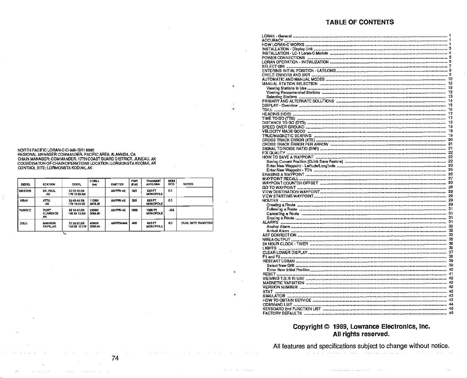
TABLE OF CONTENTS
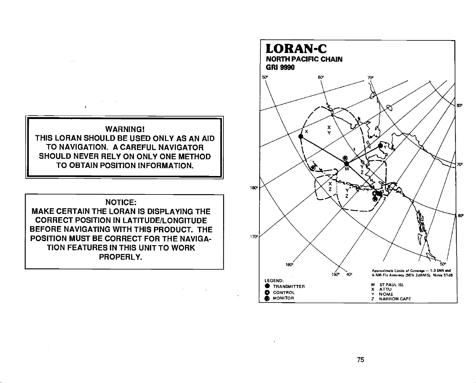
NORTH PACIFIC LORAN-C CHAIN GR1 9990
REGONAL MANAGER COMMANDER. PACIFIC MREA.
CHAIN MANAGER:CDMMANDER. 17TH CDASTGUARD DISTRICT.
COORDINATOR
CONTROL SITE: LORMDNSTA
D53IG. STATIIY4 COOn.
MASTER St PALL
XRAY ATru
YANKEE
ZULU NR0W
OF CHAIN
AK
AK
PORT
CLARENCE
AK
CAPEAK
OPERATIONS
170 l000.eW
173 1040.0!
1605312.6W 3058,05
162= 113W 3600.45
AK
KODIAK,
COSU.
670912301
624944.ON
0t14403N 2t000/
57262029) 43000/
11000/
3a7L25
LOCATION:
luuI
ALAMEDA.
LORMONSTA KODIAK.
XMTTrER
ANTFFN.42 325 625 FT
ANTFPW-42 320 62SF]
MVFR4-42
AN/FPN44A
CA
PWR
1KW)
JUNEAU,
ANTENNA
AK
AK
TRANOENT
MOIOPOI.E
601OLE
10 1350 Ft
601tW0L5
400 626
0fl4oPCt0
604
ECD
0.0
0.0
.0,6
0.0 OUAL RA1E W/OHI7000
FT
NOTES
LORAN-Genera]
ACCURACY
HOW LORAN-C WORKS
INSTALLATION
INSTALLATION - LC-1
POWER CONNECTIONS
LORAN OPERA11ON- INITIALIZATION
SELECT CR1
ENTERING INITIAL POSITION - LAT/LONG
CYCLE ERRORS AND SNR
AUTOMATICAND MANUAL
MANUAL STATION SELECTION
Viewing
Viewing
Selecting
PRIMARYANDALTERNATESOLUTICNS
DISPLAY - Overview
TD/LL
HEADING
TIMETO GO
DISTANCET000(DTG)
SPEED OVER GROUND
VELOCITY MADE GOOD 19
TRUE/MAGNETIC BEARING
CROSS TRACK ERROR
CROSSTRACKERRORPERARROW
SIGNALTO NOISE RATIO
Fix DUALITY 22
I-IOWTOSAVEAWAYPOINT
Saving
Enter New
Enter New
ERASING A WAYPDINT 28
WAYPOINTRECALL
WAYPDINTCOUNTEROFFSET
GOTOWAYPOINT 28
VIEW DESTINATION WAYPDINT 29
VIEW STARTING WAYPOINT 29
ROUTES 29
Creating
Following
Can00lling
Eraaing
ALARMS
AnochorAlarrn 32
Arrival
ASF CORRECTION
NMEA OUTPUT
24HOURCLDCK-TIMER 36
LIGHTS
CLEAR LOWER DISPLAY 37
Fl and F2 38
RESTARTLDRAN
SeledNewORI 39
Enter New Initial Poaition
RESET 41
VIEWING T.D.S IN USE
MAGNETIC VARIATION 42
VERSION NUMBER
STAT
SIMULATOR
HOW TO OBTAIN SERVICE
COMMAND LIST
KEYBOARD 2nd FUNCTION LIST 45
FACTORY DEFAULTS
-
Unil
DpIay
Loran-C Module 4
MODES ID
Stations in Use
Reornerided Stations
Stations
(HDG)
(TIC)
(X1E)
(SNR)
Current Position
Waypoint - LatitudelLongitude
Waypoinl
a Route
a Rowe 31
a Route
a Route
Alarni
-
TDs
(Quick
Save
Feature)
3
7
12
12
12
13
14
15
16
17
17
18
18
19
20
21
21
22
22
23
25
27
28
29
31
31
31
32
35
36
39
40
42
42
42
43
43
44
45
1
1
1
8
Copyright
All features and
©
1989,
All
rights
Lowrance
reserved.
specifications subject
Electronics,
to
change
Inc.
without notice.
74
PDF compression, OCR, web-optimization with CVISION's PdfCompressor
Page 4
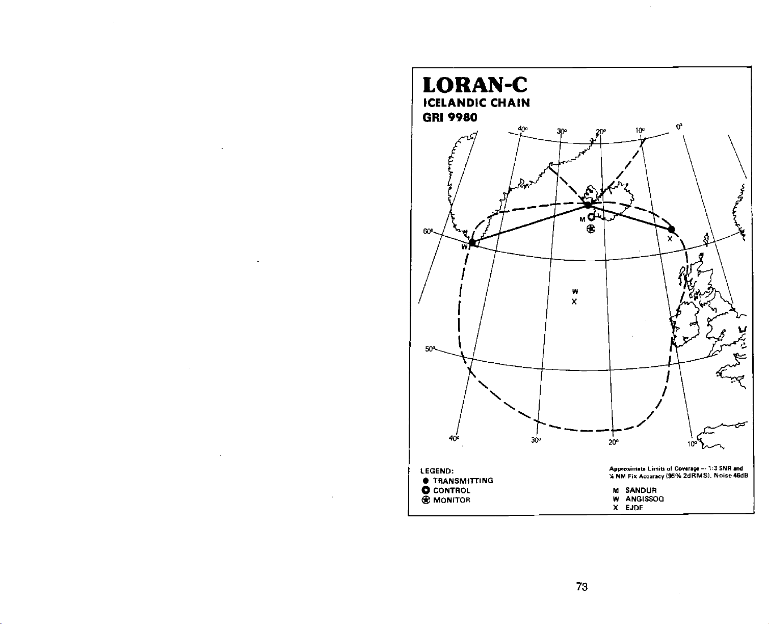
LORAN-C
ICELANDIC CHAIN
9980
GRI
LEGEND:
• TRANSMITTiNG
CONTROL
o
MONITOR
*
73
Approximat.
4 NM Fix
M SANDUR
W ANGISSOQ
X EJDE
Limit of
Accurmey jSG%
—-1:3 SNP
Conre
2dRMS). Noise 46dB
md
PDF compression, OCR, web-optimization with CVISION's PdfCompressor
Page 5
LORAN - GENERAL
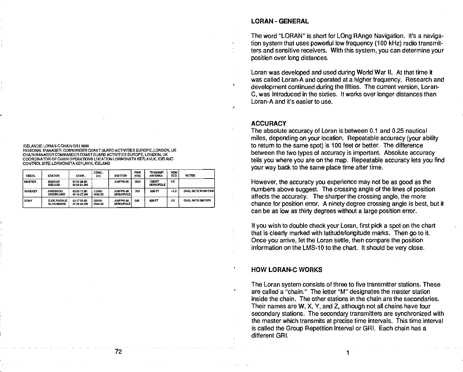
ICELANDIC LORAM.C CHAIN GRI 9980
REGIONAL MANAGER. COMMANDER COASTGUARDACTIVITIES
CHAIN MANAGER COMMANDER COASTGUARO ACTIVITIES EUROPE. LONDON,
COORDINATOR OF CHAIN OPERATIONS LOCATION LORMONSTA KEFLAVLK.
CONTROLSITE;LORMONSTAKEFLAVIK
D55. &ATJa1 C(R.
56867EA SN4DUA
W24EKEY ANGIS000
XAAY
ICELAND
OAES4LAND
EJDE.FAEAOE
IS..OESWFK
6454 26.64
5521,5W
5959 I7N
451627.5W
6217 55.64
0704 26,5W
ICELAND
CDULS.
Iv,) (MITtEn
AWFFSJ.45 '500 I350FT
11055!-
4068.62
35555!
2814$4
NQFFW4S
5flIOLE
NWFPN-44
MIY4C9OLE
EUROPE, LONDON,
PWR
TRMSSMff
ANTB4MA
1KW)
Ma40Pa6
765 625 FT +1.0 DUAL RATE W?09l7920
325 625 FT 0.0 DUAL RATEOWI757O
UK
ICELAND
UK
N62I
LCD NOISE
0,0
The word "LORAN" is short
lion
system
that uses
ters and sensitive receivers. With this
position
Loran was
was
over
developed
called Loran-A and
development
was introduced in the sixties. It works over
C,
distances.
long
continued
for
powerful
and used
operated
during
LOng RAnge Navigation.
low
frequency (100
system, you
during
the
World War II.
at a
higher frequency.
fifties. The
Loran-A and it's easier to use.
ACCURACY
The absolute
accuracy
miles, depending
to return to the same
between the two
tells
your way
However,
numbers above
affects the
chance for
where
you
back to the same
the
accuracy you experience may
accuracy.
position
you
suggest.
can be as low as
of Loran is between 0.1 and 0.25 nautical
on
types
thirty degrees
location.
your
is 100 feet
spot)
of
accuracy
are on the
place
The
The
sharper
error. A
ninety degree crossing angle
Repealable accuracy (your ability
or
is
important.
map. Repeatable
time after time.
crossing angle
the
crossing angle,
without a
kHz)
can determine
current
longer
better.
The
Absolute
accuracy
not be as
of the lines of
large position
It's a
naviga-
radio transmit-
your
At that
time it
Research
version,
Loran-
distances than
difference
accuracy
lets
you
as the
good
position
the more
is
error.
best,
but it
and
find
If
wish to double check
you
that is
Once
clearly
marked with
you arrive,
let the Loran
your Loran,
latitude/longitude
settle,
information on the LMS-1 0 to the chart. It should be
first
then
pick a spot
marks. Then
compare
the
on the chart
go
position
close.
very
to it.
HOW LORAN-C WORKS
The Loran
system
are called a "chain." The letter
inside the chain. The other stations
Their names are
secondary
stations. The
the master which transmits at
is called the
consists of three to five transmitter stations. These
W, X, Y,
and
secondary
Group Repetition
"M"
designates
in
the chain are the secondaries.
Z,
although
transmitters are
precise
time intervals. This time interval
Interval or GRI. Each chain has a
the master station
not all chains have four
synchronized
with
different GIRl.
72
1
PDF compression, OCR, web-optimization with CVISION's PdfCompressor
Page 6
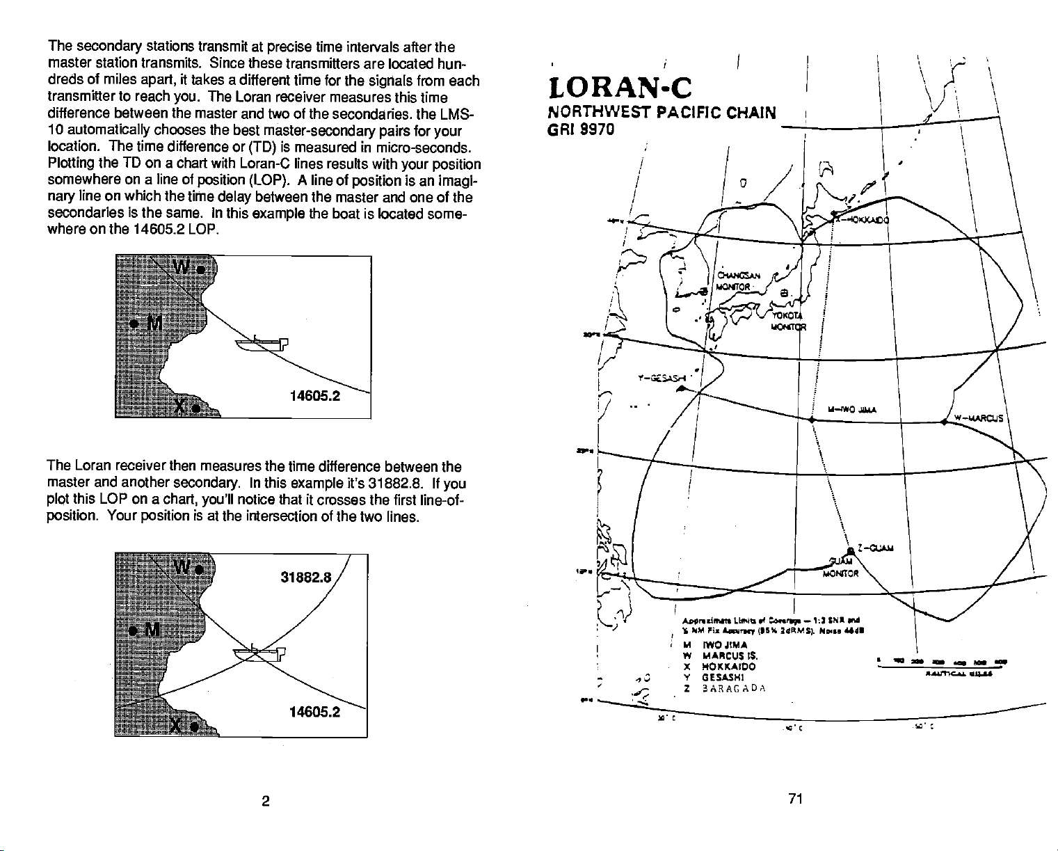
The
secondary
stations transmit at
precise
time intervals after the
master station transmits. Since these transmitters are
dreds of miles
transmitter
to
reach
difference between the master and two of the
10
automatically
location. The
Plotting
time difference or
TO
the
somewhere on a line of
line on which
nary
secondaries is the
it takes a different time for
apart,
The Loran
you.
receiver measures this time
the
secondaries, the LMS-
chooses the best
master-secondary pairs
is measured in
(TO)
on a chart with Loran-C lines results
position (LOP).
the time
same.
In
delay
this
example
A line of
between the master and one of the
position
the boat is located some-
signals
with
where on the 14605.2 LOP.
located hun-
from each
for
your
micro-seconds.
your position
is an
imagi-
LORAN-C
NORTHWEST PACIFIC CHAIN
9970
GRI
The Loran receiver then measures
master and another
this LOP on a
plot
position.
Your
secondary.
chart,
position
you'll
is at the
the time difference between the
In this
notice
intersection of the two lines.
example
that it crosses the first line-of-
it's 31882.8. If
2
you
0
I
—
—.
.,
1
—-_
Asprnlwdn
)M
S
II
W
X HOXXAIDO
LS,t of
Fis
£ncy (P5% 2flMS(.
IWOJIMA
MARCUS IS.
t GESASHI
2 3ARAGADA
__..._.___.___
t.nr.p
'C.
71
—
13 $fl rid
Pa... 44d1
C
-.
PDF compression, OCR, web-optimization with CVISION's PdfCompressor
Page 7
All Loran-C receivers work on this
also
display latitudeflongitude.
and, using
longitude position
longitude
a
complex
data. You can
on the LMS-1 0 to determine
mathematical
The receiver takes
principle.
formula,
display
your
Most modern receivers
the TD information
converts it to latitudef
both TD's and latitude!
position.
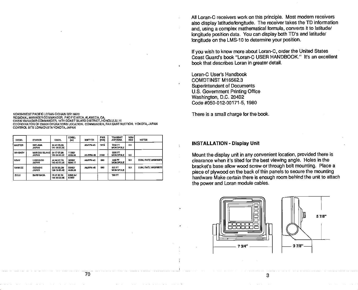
NORThWEST PACIFIC LORAN.C CHAIN CR1 9970
REGIONAL MANAGER COMMANDER. PACIFICAREA, ALMAEDA, CA.
CHAIN MANAGER
COORDINATOR OFCHAIN OPERATIONS LOCA11ON. COMMANDER. FAR EASTSECTION. YOKOTA,
CONTROL SITE
DES'S. &ATTa4 CDOR.
MASTER M0JI
WHEXEY IMRCUEISLAND
XMY HOKKAIOO
YANKEE GESASHI
ZULU BARRIGADA 1327E0.IN
COMMANDER,
LORMONSTAYOKOTA,
JAPAN
JAPAN
JAPAN
JAPAN
14THCOASTGUARD DISTRICT,I-IONOLULU, HI
JAPAN
244E03.E14
141193020
241707.914
153 58 53,2E
424437.111
1134309.25
283825.011
1280886.45
444933.00
COBIL
lusI
110801
4283.58 ANIFPR145
38080!
8686.17
58080/
448328
2528.84$
81080
XMITrER
AWFFN-45 1815
AN/FPW4S 800
ANPPN'IS 828 FT
PWR
(XW}
2150
500
WNSMFr
ANTENLA
1380FT
Magopa.E
1280 FT
MWOPOLE 0.0
G2SFT
Ma4OPOLE
Ma40LE
7SOFT
N0l
EUD NOTEE
0.0
0.8 DUALRATEW/0RI5970
0.0 DUAL RATE W10918970
JAPAN
It
wish to know more about
you
Coast Guard's book
book that describes Loran in
"Loran-C USER HANDBOOK."
greater
Loran-C User's Handbook
COMDTINST
Superintendent
U.S. Government
Washington,
Code
#050-012-00171-5,
There is a small
INSTALLATION
Mount the
clearance when it's tilted
Ml 6562.3
Documents
of
Printing
D.C. 20402
charge
-
Display
display
unit in
Office
1980
for the book.
Unit
convenient location,
any
for the best
bracket's base allow wood screw
of
piece
plywood
hardware Make certain
the
power
and Loran module
on the back of thin
there is
cables.
Loran-C,
detail.
viewing angle.
or
through
panels
enough
order the United
States
It's an excellent
provided
there is
Holes in the
bolt
mounting.
to secure the
room behind the unit to
Place a
mounting
attach
70
3
PDF compression, OCR, web-optimization with CVISION's PdfCompressor
Page 8
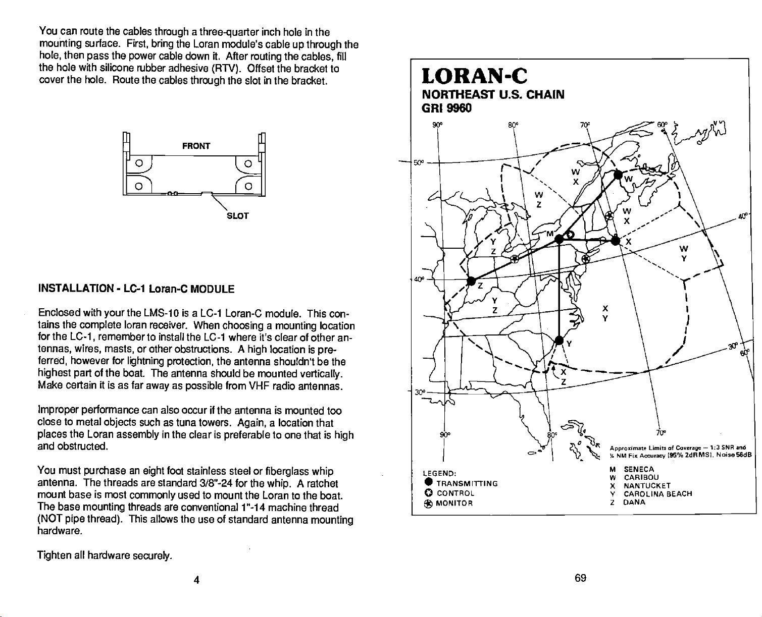
You can
mounting
hole,
the
cover the hole.
route the cables
surface.
then
pass
the
through a three-quarter
First,
bring
cable down it. After
power
hole with silicone rubber adhesive
Route the cables
the Loran
(RN).
through
inch
hole
module's cable
routing
the
Offset the bracket to
the slot
SLOT
in
the bracket.
in
up
through
cables,
the
the
fill
INSTALLATION
Enclosed with
tains the
for the
tennas, wires, masts,
ferred,
complete
LC-1,
however for
highest part
Make certain it is as far
Improper performance
close to
places
and
You must
antenna.
metal
the Loran
obstructed.
purchase
The threads are standard 318"-24 for the
mount base is most
The base
mounting
(NOT pipe thread).
hardware.
Tighten
all hardware
-
LC-1 Loran-C MODULE
the LMS-1O is a LC-1 Loran-C module. This con-
your
loran
receiver. When
remember to install the
or other
lightning protection,
obstructions.
of the boat. The antenna
as
away
can also occur if the antenna is mounted too
objects
such as tuna towers.
assembly
an
eight
commonly
threads are conventional 1"-14 machine thread
This allows the use of standard antenna
securely.
possible
in the clear is
foot stainless steel or
used to mount the Loran
4
choosing a mounting
LC-1 where it's clear of other an-
A
high
location is
location
pre-
the antenna shouldn't be the
should be mounted
vertically.
from VHF radio antennas.
Again,
preferable
a location
to
one that is
that
high
fiberglass whip
A
whip.
ratchet
to the boat.
mounting
69
PDF compression, OCR, web-optimization with CVISION's PdfCompressor
Page 9
The cable
supplied
cable lilt's too
with the LC-1 is
Instead,
tong.
coil and store it out
thirty
feet
Do not cut the
long.
of
the
extension cable is available it the cable is too short. Ask
call
your
Service
local service center or the Lowrance
department
for more information.
Factory
Customer
way.
your
An
dealer or
NORTHEAST U.S. LORAN-C CHAIN GRI 9960
REGIONALMANAGERCOMMANDER.
CHAIN MANAGER
COORDINATOR OF CHAIN OPERATIONS
CONTROL SITE: LORSTA
00210. STATIa4
WASTER
WHISKEY
XRAY NNJI1JCKET
YAM(EE CARQJ(A
ZLLU DANA *4 3551 (7.91 540
COMMANDER. ATLANTICAREA, NEWYORK, NY
SENECA, NY
NY 424250.621
SENECA,
I.E
CARIBOU,
MA
EECH,NC
ATLJTICAREA.
LOCATION: LORSTA SENECA, NY
CDEU.
COCA.
754933.9W
4648271
575537.7W
4115 ThEI.
555835.1W
340346.IN
775446.7W
6729121W 3152.20
(56)
Il0
2757.20
250
1502.93
39060!
3221.64
PWR
(KWI
NY
IRAPffiMIT
ANTBNA
700FT'
-
MGIOFOLE
MG4OFOLE
M4OPQ.E
POH
ECU NOIES
0.0 DUAL RATE 500915972
DUAL RATE W/0RI5930
'5.5 DUAL RATE W!0R18570
NEWYORK.
XMTTER
MOIFFT'144 800
(56HC0SI
N4WP9442 360 SLT 0.0 DUAJ. BAlE W/OBE93O
MUFPR412 320 525 FT 05
WFFI4A2 550 'TIP 0.0 DUALRATEW/ORI7SSO
A9UFFS+44 460 625 PT
The LC-1 can
it desired.
mast,
be attached to a swivel bracket or hollow extension
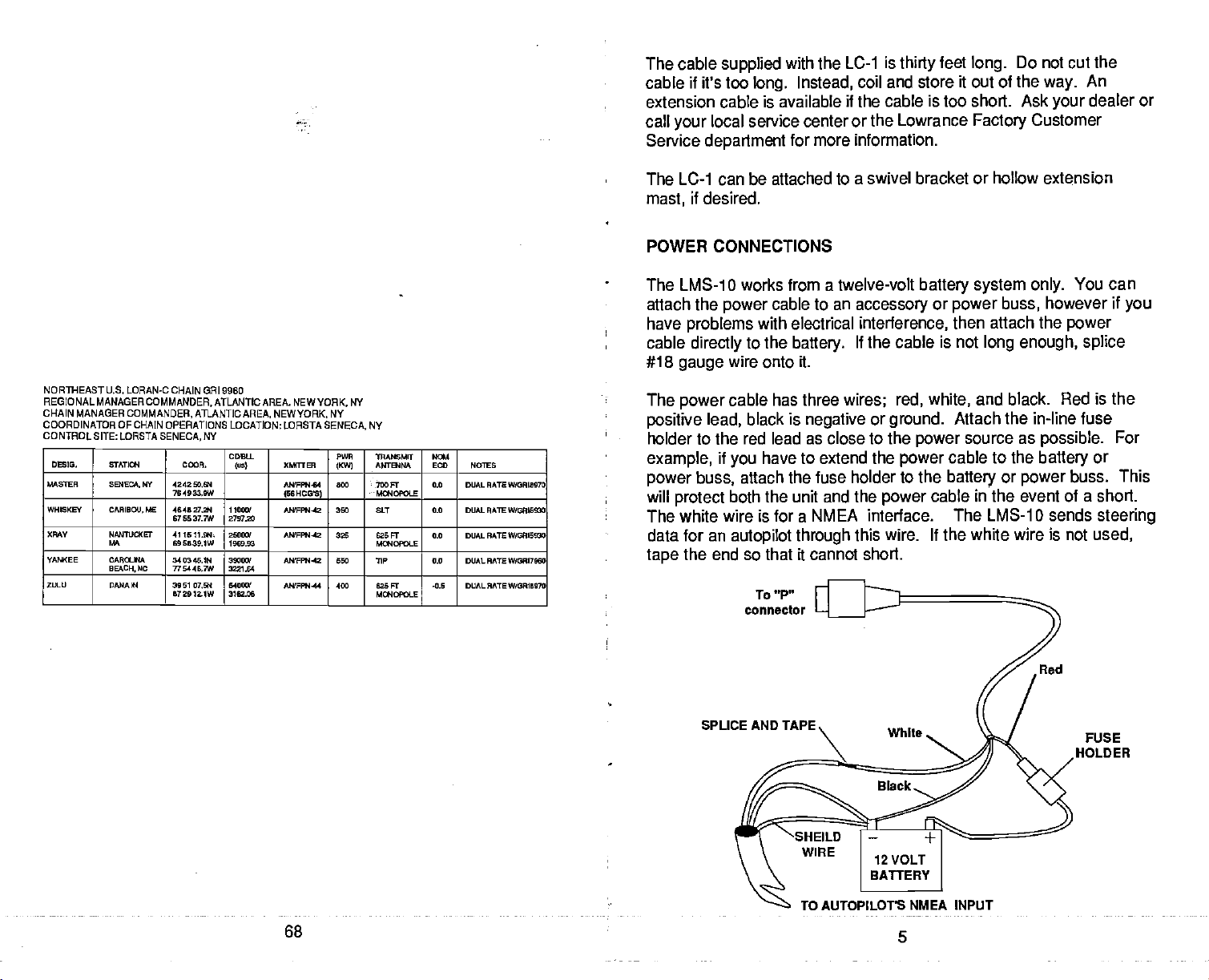
POWER CONNECTIONS
The LMS-1
attach the
have
cable
#18
The
positive lead,
0 works from a twelve-volt
power
problems
directly
gauge
power
to an
cable
with electrical
to the
battery.
wire onto it.
cable has three
black is
negative
accessory
interference,
If the cable is not
wires; red, white,
or
ground.
holder to the red lead as close to the
if
example,
power
will
buss,
protect
The white wire is for a
data for an
end so that it cannot short.
the
tape
have to extend the
you
attach the fuse
both the
unit and the
NMEA interface. The LMS-1 0 sends
autopilot through
To "P"
connector
power
holder to the
power
this wire. If the white wire is not
battery system only.
or
power
buss,
then attach the
long enough,
You can
however if
power
splice
and black. Red is
Attach the
power
cable to the
battery
source as
in-line fuse
battery
or
power
possible.
or
buss. This
cable in the event of a short.
used,
you
the
For
steering
SPUCE AND TAPE.
TO AUTOPILOT'S
68
PDF compression, OCR, web-optimization with CVISION's PdfCompressor
NMEA INPUT
5
FUSE
HOLDER
Page 10
To connect an
cable from the
Guide's
and the shield to the black wire on
power
the shield to the
instructions.
wiring
autopilot
autopilot's
cable. Solder the
autopilot.
to the
NMEA
See
LMS-1O,
your autopilot's
attach a
to the white wire on the Nay-
intput
the
conductor
power
ground
shielded,
of the twisted
cable. Do not connect
manual for more
twisted
pair
pair
Once the cable is
See the NMEA
LORAN OPERATION
connected,
Output
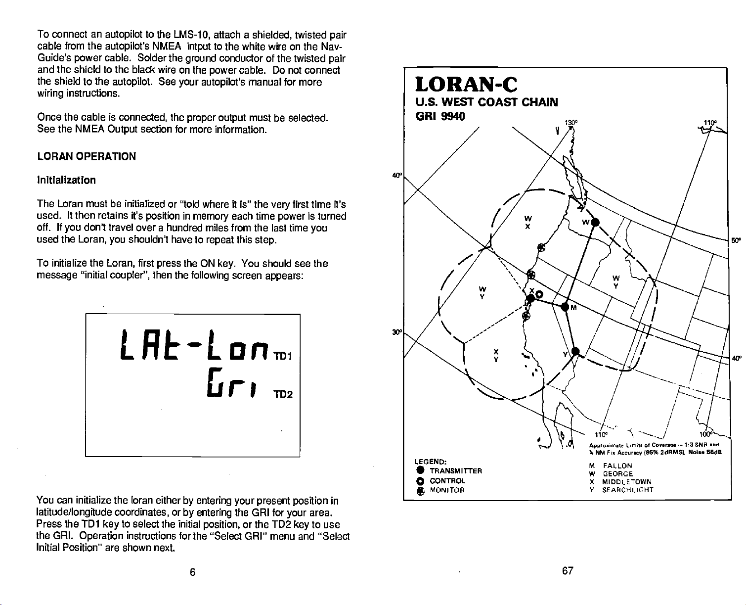
Initialization
The Loran must be
used. It then
off. If
used the
To initialize the
message
don't travel
you
Loran,
"initial
initialized or "told where it is" the
retains ft's
you
Loran,
coupler",
LREOLORTD1
the
proper
section for
have to
press
in
the ON
position
over a hundred miles from the last time
shouldn't
first
then the
output
more information.
memory
repeat
key.
following
5
must be selected.
very
each time
this
You should see the
screen
power
step.
appears:
TD2
first time it's
is turned
you
5Q0
40°
You can initialize the loran either
latitude/longitude
Press the TDI
the GRI.
Initial Position" are shown next.
Operation
coordinates,
to select the initial
key
instructions for the "Select GRI" menu and "Select
or
by entering your present position
by entering
position,
6
the GRI for
or the TD2
your
key
in
area.
to use
67
PDF compression, OCR, web-optimization with CVISION's PdfCompressor
Page 11
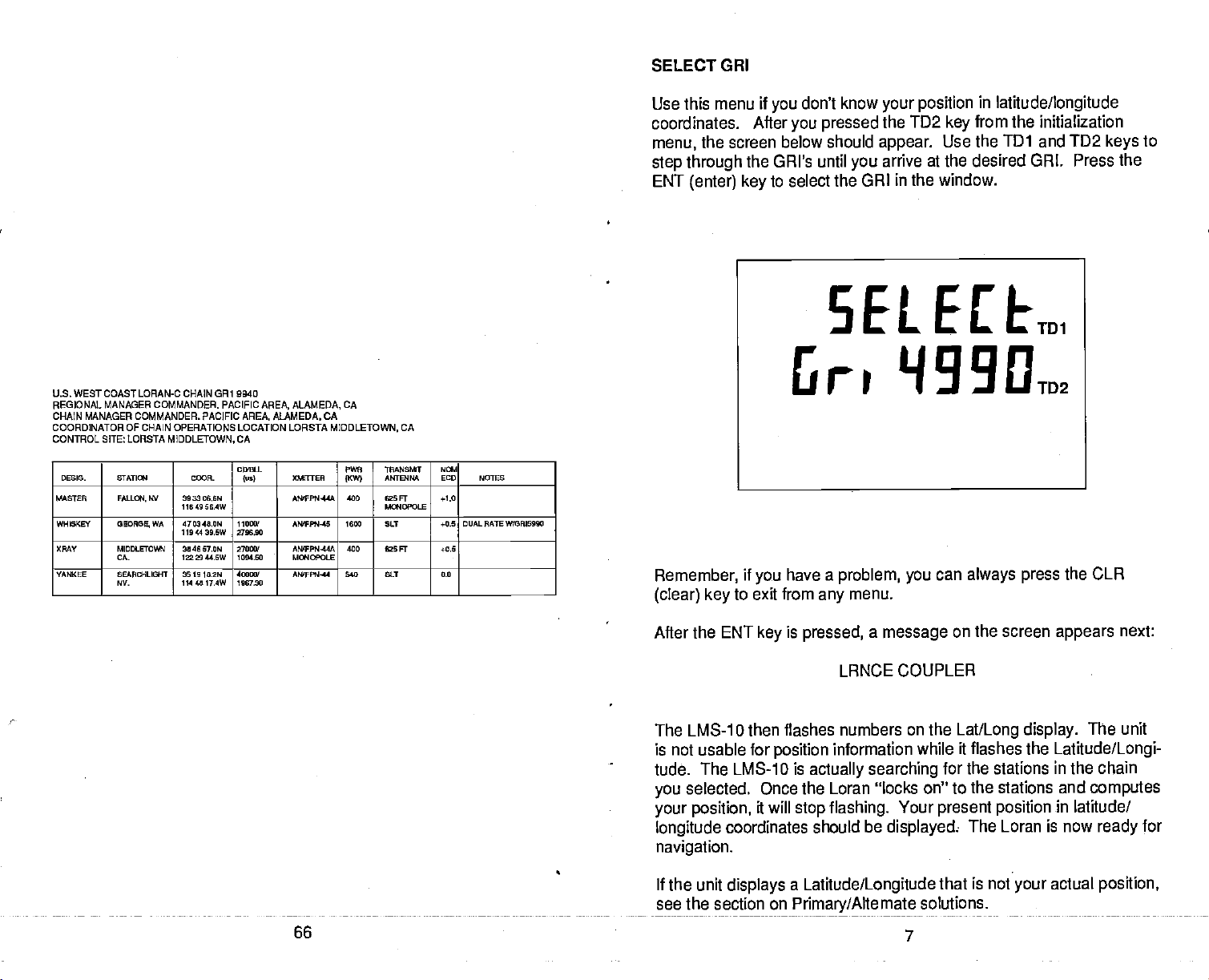
SELECT
GRI
U.S. WEST COAST LORAN-C CHAIN CR1 DO40
REGIONAL MANAGER COMMANDER. PACIFIC AREA. ALAMEDA, CA
CHAIN MANAGER COMMANDER. PACIFIC AREA. ALAMEDA. CA
COORDINATOR OF CHAIN OPERATIONS LOCATION LDRSTA MIDDLETOWN, CA
CONTROL SITE: LCRSTA
DESIS- SIATIaI ODOR-
MASTER FALOCH.
WHIGKEY
OMY MIDDLETOWN
YANKEE SEARCHLIGHT
0EOR00
CA-
NV-
MIDDLETOWN,
WV 3033066W
11649 56.4W
WA 470348.0W
1104439.6W
3046 570W
1332944.5W
361910.2W
1144817.4W
CA
C040.L
los)
110001
270690
270
1254.00
400
1067.30
PINE
008T1E5
MJIFPN44A
AI81Pt445 1600 50.T i-OS DUALRATEW(ORIS990
AMIFPO4-44A
Ma4OPOLE
AW'Ffl14l 640 SIT 0.0
111.445081
ANTEHNA
0KW)
400 5
400 030 Fr +0.5
F
Ma4DPOLE
NGl
ECD NOTES
+1.0
Use this menu if
coordinates.
menu,
the screen below
step through
ENT
(enter)
Remember,
(clear) key
After
the GRI's until
key
if
you
to exit from
don't know
you
you pressed
should
to select
the GRI in the window.
have a
any
your position
the TD2
appear.
arrive at the desired GRI. Press the
you
problem, you
in
latitude/longitude
from the initialization
key
Use the
can
TD1
always press
and
menu.
TD2
keys
the CLR
to
After the ENT
key
is
pressed,
a
message
on the screen
appears
next:
LRNCE COUPLER
The LMS-tD then flashes numbers on the
is not usable for
position
tude. The LMS-1 0 is
selected.
you
your position,
longitude
Once the Loran 'locks on" to the stations and
will
it
coordinates should be
information while it flashes the
actually searching
stop flashing.
for the stations
Your
present position
displayed:
Lat/Long display.
The Loran is now
The unit
Latitude/Longi-
in
chain
the
computes
in
latitude/
for
ready
navigation.
If the unit
see the section on
displays a Latitude/Longitude
Primary/Alternate
66
PDF compression, OCR, web-optimization with CVISION's PdfCompressor
that is not
solutions.
7
your
actual
position,
Page 12
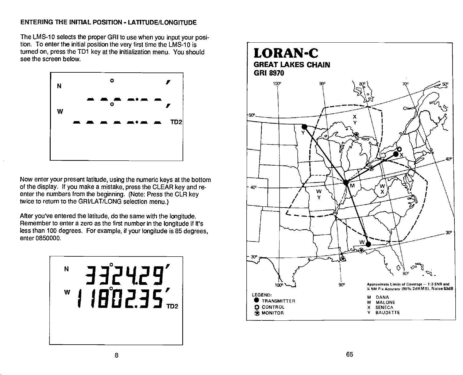
ENTERING THE INITIAL POSITION
-
LATITUDE/LONGITUDE
The LMS-10 selects the
tion. To enter the initial
turned
see the screen below.
on,
press
N
the TD1
proper
position
GRI
to use when
the
very
at the initialization
key
first time the
a a a a. a a
0
w
a a a a a a a TD2
Now enter
of the
enter the numbers from the
twice to return to the GRI/LAT/LONG selection
your present latitude, using
If
display.
you
make a
beginning. (Note:
mistake,
the numeric
the CLEAR
press
you input your posi-
LMS-1 0 is
menu. You should
at the
key
bottom
and re-
key
keys
Press the CLR
menu.)
After
you've
Remember to enter a
less than 100
enter 0850000.
entered the
zero as the first number in the
degrees.
N
latitude,
For
example,
do the same with the
longitude
if
your longitude
longitude.
if it's
is 85
degrees,
33°2'{29'
w
J
IB°Q2.3S.
8
PDF compression, OCR, web-optimization with CVISION's PdfCompressor
65
Page 13

The
LMS-1O,
like most Loran receivers,
hundredths of a minute. Charts
seconds. It's not
minute for
your
initial
necessary
position.
to convert seconds to hundredths of
NOTE
typically
uses
use
degrees,
degrees,
minutes,
minutes,
and
and
a
GREAT LAKES LORAN-C CHAIN GRI 8070
REGIONAL MANAGER COMMflDER, ATLANTIC AREA, NEWYORK,
CHAIN MANAGER
COORDINATOR OF CHAIN OPERATIONS LOCATION: LORSTA SENECA, NY
CONTROL SITE: LORSTA
0610. STATI4 CR.
WOOER DANA, IN 3951 DIal
WHISKEY OAALGIE. ft
XRAY
YANKEE BAU000TE 4590 49.0K 44020/ AWFPI4I2 550 730 FT 010
COMMANDER,
-
W/ 424200.SN
SE4ECA,
ATLANTICAREA. NEWYORK, NY
NY
SENECA,
0D90.
("SI
512912.1W
3050 30.771
251009.9W
764092.962
11000/
9355.11
25020/
3062.50
XMIUER
ANfFPO+44 450
NWFFII-64
ISSHCOS)
UFPN64
ISSHCGS)
NY
PWR
7M?5&T
ANTE4NA
01'WI
625 F
M0/IOPOLE
550 700 Ft
MC*IOPOLE
550 700 FE
I.fllOPLE
NaA
EDO NOTES
0.0 DUAl. RATEW/0R19960
DUAL RATEW/0017550
0.0
0.0 0tLL AAIEW/GR9060
You don't have to use
that is close
mate
position,
latitude/longitude.
is
usually
by
the
call
Then use the
exact
your
sufficient. If
airport
closest to
position.
Your screen should look like the
you've
England,
"1D2"
Once
ENTER
display.
entered the
no
change
This switches the
key.
you've
entered the correct
The LMS-1 0 then
key.
The unit is
position.
is
searching
the LMS-10 "locks on" to
numbers
take
up
stop
to five
flashing
minutes,
about two to three minutes
Remember,
flashes the
Now that
unless
stores the last known
unit
on,
the Loran is
latitude/longitude.
you've
you
come thié
move a
long
it will use the last GRI and
If
your longitude
necessary.
longitude
for the stations in the loran chain. Once
the stations and
and
your
perhaps
to "lock on" to
not usable for
far, you
distance with
position
in its
position
to initialize the
don't
you
and ask their
you
know
position they give you
one at the bottom of
is west of
If it's east
longitude, press
Loran;
approxi-
your
position
as a initial
8 after
page
Greenwich,
the
to east.
latitude/longitude position, press
flashes numbers on the
Lat/Long
computes your position,
unit is
ready
for
longer. Typically,
navigation.
the LMS-10 takes
This
your position.
navigation during
shouldn't need to do it
the time it
again,
the Loran oft. The LMS-1 0
memory,
position
so each time
that was in use.
you
one
in
the
the
may
turn the
a new GRI
page
(SNR)
are
displayed.
39.
64
If
need to re-initialize
you
or Initial
Position,
CYCLE ERROR
The LMS-1 0
and
cycle
displays cycle
errors with labels on
see the RESTART LORAN section on
AND SNR
the
errors and low
NOTE: These errors won't be
Press the TD/LL
to show TDs
key
either
loran,
the
display.
shown if
latitude/longitude
and error labels
9
by entering
to noise ratios
signal
(if activated).
PDF compression, OCR, web-optimization with CVISION's PdfCompressor
Page 14

If a low
the CYC label. In
plays
line. Press the TD1
top
which
one(s)
TD that has a
choose another
to noise ratio or
signal
have low
poor
SNR. If
station
error is
cycle
this
example,
or TD2
to noise ratios. Do not
signal
the SNR label shows next to
to rotate
key
the unit is in
automatically.
found,
through
automatic,
the
LMS-1 0 dis-
the TDs to see
navigate
with a
the LMS-1 0
the
should
SNRq535 935
CYCEEIBE 5.23
The
rotate
have a
navigation.
AUTOMATIC and MANUAL MODES
The LMS-1 0 chooses the
signal strengths
monitors the
best stations to use.
cycle
through
cycle
error
display
the
displays using
error.
Again,
to use when
crossing angles
works
identically
the TD
do not use
stations with the best
in
ft's
the automatic mode. It
and
signal strengths
to the SNR
to find which stations
keys
stations with a
crossing angles
to determine the
TD1
102
display. Simply
error for
cycle
and
continuafly
400
r
However,
stations. For
tions,
waypoint. Navigating
waypoint
mode
also
there are
need to use those same
you
may
it from
stops
places
theunit in the
times when
example,
with
result in
changing
don't want the unit to switch
if
position
you
save
you
stations other than the ones used to save a
manual mode.
a
stations to
errors.
stations.
10
waypoint using
Placing
Choosing
one set of sta-
navigate
the unit in the manual
back to that
the stations
yourself
63
PDF compression, OCR, web-optimization with CVISION's PdfCompressor
Page 15

To
change
press
from automatic to manual,
the TD/LL
key.
The screen
USEd
SELECE
first
press
shown below
the 2nd
appears.
e
a
TUl
e
a
TD2
key.
Next,
MEDITERRANEAN SEA LORAN-C CHAIN GRE 7990
REGIONAL MANAGER
CHAN MANAGER COMMANDER. COAST GUARD ACTIVITIES
COORDINATOR
CONTROL SITE:
DEBIt SrATIa4 CCOR.
MASTER SEUJA
XPAY
YAM(EE
2ItU ESTTr
COMMANDER,
OF CHAIN OPERATIONS LOCATION: LORSTASELLIA
LORSTA SELLIA
MItNA,FThLV
LM'PEDLJSA
FTALY
IOAROABLJRUN
TURKEY
SPAIN
COASTGUARD ACTIVITIES
MARINA, ITALY
0(05th
(us)
265220,6H
1643(6.26
3531 BOON
12313020
4056 BOON
275200.SE
42 03 BOON
0312 lOSE
110001
0705,96
200001
327326
470001
3909.74
XMT(6R
ANPFP4-39 166 625FT
A'TtS 326 625 Fr
M'UFPN-39 16$ 625 FT
M0F90630 lEO 635 Ft
EUROPE. LONDON,
LONDON. UK
EUROPE,
MARINA,
PWR
1KW)
ITALY
TAANSMFr
A&TS'tA
M4OLE
M014OPOLE
M01DPOLE
MOFOLS
UK
9O
EGO NOTES
50
0.0
0,0
00
Press the TD1
mode. Press the TD2
to see if the unit is
key
key
the screen shown below
no nRUE
Now
press
TD2
key
is
pressed,
key
To exit from these
CLR
(clear)
TD1
if
the
you
key
want the non-auto
unit returns to the
the
menus without
key.
in
to switch modes.
appears.
RUED
if
want the automatic
you
(manual)
position display.
changing
the
automatic
If
the
or manual
TD2
key
is
El
mode,
mode. After the desired
the
mode, simply press
or
press
pressed,
the
the
it
Another
is to
press
NON
AUTO",
to see
way
5,6,ENT.
depending
62
PDF compression, OCR, web-optimization with CVISION's PdfCompressor
LMS-1 0 is in the manual or automatic mode
the
The
display
on
will show "USING AUTO" or "USING
the current mode.
11
Page 16

MANUAL STATION
SELECTION
Viewing
If
you
use the Manual Station
currently
below
Stations In Use
wish to
appears.
use stations other than the ones chosen
in use
by pressing 1,4,
Selection
option.
ENT. A
You can view the stations
screen similar to the one
DIaL'S
The "U" stands for "stations in use". The TD
represented by
always
next station's TD is
station's TO is
tions used
example,
return to the
shown with a "0". In this
the first
31883.30,
the LMS-1 0 are shown with
by
the unit is
Lat/Long display.
number
14598.78,
using
so
so it's
represented
stations
in
the TD. The master station is
sample
it is
screen,
represented by
a dash above them. In this
and 6. Press the GLR
0, 4,
the
by
for each station is
the master is
"1 ". The next
a
and so on. Sta-
3,
by
LMS-1O,
the
0,
to
key
Viewing
You can view the
1
,5,ENT.
appears.
"Recommend".
number in the TD.
this
sented
The stations the
above them.
0, 4,
Recommended Stations
stations the LMS-1 0 recommends
A
screen similar to the one at the
The
symbol
by
screen,
"1".
The next station's TD is
In
sample
and 6. Press the CLR
that looks like an
The TD for each station is
The master station is
the master is
LMS-1 0 recommends for use
this
example,
the next station's TD is
0,
the LMS-1 0
to return
key
12
by pressing
of the next
top
upside
represented by
down "L" stands for
represented
always
to the
shown
are shown with a dash
recommends
Lat/Long
page
the first
by
with a "0". In
repre-
a
and so on.
3,
stations
using
display.
61
PDF compression, OCR, web-optimization with CVISION's PdfCompressor
Page 17

Selecting
Stations
SOUTHEAST U.S. LORAN-C CHAIN FRi 7980
REGIONAL MANAGER COMMANDER. ATLANTICAREA.
CHAIN MANAGER COMMANDER. ATLANTICAREA.
COORDINATOR OF CHAIN OPERATIONS
CONTROL SITE: LORSTA
DESEG. ETATI4 COCA.
MASTER MALIE. H. 305028.7W
WHISKEY
XMY RAflIOM0'
YA9EEE
ZILU CARaIMA
O60NGEVILLE
LA
VOLE,1X
JUFOTER.R.
NC
EEACH,
MALONE.
031009.3W
304223.81
901943.EW
2531 0611,1
975000.10!
2701 GnAW
900653.40!
340340.1W
775446.70!
FL
NEWYORK. NY
LOCATION:LORSTA MALONE, FL
CG'SLS.
(us)
11009/
1Oct54
22020!
444370
43020/
2201.89
59000/
0642.70
NEWYORK,
XMF1TEH
ANIFF14-E4
lEE HOG'S)
AWFFI4-E4
108H0G'S)
ANIFFN'64
132HCG'S)
AOVFFF4'lZ 309
AOVFFtI'42 560 liP tO DIJALRATEW/0818860
NY
PWR
TRA)$M/T
ANTesa
(10W)
809 700 Fl'
MGIDPCLE
800 700FF
MeIOPOLE
400 700 Fr
MaIDPOLE
625FF
M0100POLE
N4
ECD NOIES
0.9 DUAL RATE W/ORI 8970
'0$
0.0
0.0
NOTE:
Selecting
To select the
the
Again,
of the screen indicates this is the station select screen.
right
the TDs for each station are
the ID. For
stations
stations,
example,
places
press
a 3 is
the
displayed
31883.25.
To select the
sponds
0
to select the Master station. A dash
key
display, signifying
with a ID
stations,
to the first number in the desired
it's selected. Press the 3
beginning
with
the number on the
press
and so on.
3,
- S
13 I3E
the LMS-1 0
ENT
and
1,7,
represented by
for a station whose
TD. For
appears
key
in
the manual mode.
The letter '5" at
keys.
the first
number in
TD
keypad
that corre-
example, press
over the 0 on the
to select the station
is
the
After
you've
stations
should
PDF compression, OCR, web-optimization with CVISION's PdfCompressor
60
selected the desired
you've
display
chosen
a
latitude/longitude
stations, press
are locked with
after a short wait.
13
good signal strengths,
the ENT
key.
If the
the unit
Page 18

PRIMARY AND ALTERNATE SOLUTIONS
The Loran
difference between
difference results in a line of
position
normally
cross is
A mathematical formula in
the
latitude/longitude position.
position
(The
line.)
qualities
other side of the
positions
usually
position
baseline,
could be
your position
If
the
TD1
primary
then show a new
label 'ALT"
nate solution is in effect. If the "ALT"
solution is in effect.
in
latitude/longitude
baseline is
It's
possible
and
are called
far
apart, making
far from
the difference between
only
need to switch from the
you
6
2nd,
keys.
if
key
you
solution. The
appears
determines its
the master and two other stations. Each time
your present position.
the Loran receiver uses To's to determine
an
imaginary
for the Loran to lock onto the
signal strengths,
baseline from
the
primary
it
easy
actual
your
a few miles. For this reason
when
initializing
The screen shown
want the
alternate solution or
latitude/longitude
in the
This
upper
position.
position by measuring
position.
Due to the nature of
can be on either side of the baseline.
line
connecting
but show the
your present position.
and altemate solutions.
to tell if the Loran is
location.
the alternate and
or
using
primary
process
left corner of
the time
Where these two lines of
This is called a "fix."
Loran, your
two
stations
stations,
latitude/longitude
However,
if
alone,
you're
it's
give good
These two
They're
displaying
close to the
primary
important
the Loran.
to the
alternate
below
appears. Next,
press
will
flash for a few
takes a few seconds. The
solution,
the TD2
the screen
label is not
on,
the
primary
in
a
straight
on the
a
solution
to know
press
press
for the
key
seconds,
if
the alter-
fix
700
@3°
the
RLEe a
Pr
i
14
TD1
:TD2
PDF compression, OCR, web-optimization with CVISION's PdfCompressor
Page 19

To switch back to the
primary
solution,
simply repeat
the
above
steps.
NORWEGIAN
REGIONAL MANAGER.
CHAIN MANAGER
COORDINATOR OF CHAIN OPERATIONS LOCATION: LORAN-C DETAIL
CONTROL SITE: LORMONSTA
06510. STATI04
OMSOWA EJOE,FAEAOE
XFLAY
WHISKEY SYLT
YANKEE 5NODUR
ZULU .065 MAY84
SEA
LORAN-c CHAIN GRI 7970
COMMANDER.
COMMANDER,
DEFIAVIK,
tOGA.
65..DENMAAK
BONORWAY 662606J
0EAMAOff
C0.AND
NWAY
6217 SOON
070426.5W
14 2747,0E
5446 8.001
0617303E
646426,601
85621.6W
72 6462.7W
064350.7W
COAST GUARD ACTIVITIES
COAST GUARD ACTIVITIES
ICELAND
CDLLL
110004
4046,10
260004
4065.62
460%!
2944$4
60000!
3216S1
XMITTEH
us)
AN!ffP6f44 325 025 FT
AFSFFN-31 166 625Fr
ANIFFN.42 325 626 Fl'
AN/F004'45 1600 1SEOFT
AN'FFAI'39 166 626 FT
EUROPE, LONDON,
EUROPE. LOND. UK
PWR
1KW)
KEFLAVIK,
1B4N6140
ANTBINA
MCX'ODVOLE
MOIDFOLE
MONOPOLE
54a4DPOLE
%fl4DPOLE
UK
ICELAND
NQI
LCD NOTES
32 DUALMTE W!0R1780
0.0
0.0
0.0 DUALA4TEW/0R17530
0.0
Check
latitude/longitude.
your
known
position
They
navigate normally.
DISPLAY-Overview
The LMS-lO
show
your present position
lines can show
Go,
Speed
Good,
display
Heading,
Over
and more.
Ground,
ALT
SNR535
CVCSIJBS
CMD
5-I
WPT gq3vMc
against
the Loran after it
should be the same. If
has four lines of
in
latitude/longitude
Cross
True or
information. The
Track
Error,
Magnetic Bearing, Velocity
'411
5.23
XTE
1112
displays
use the Loran and
so,
or TD5. The lower two
Time To
Go,
935
a new
two lines
upper
Distance To
Made
.4,
TD1
The arrows at the
used when a
the anchor
waypoint
alarm is
The SNR and CYC
error
cycle
The
problem
at the bottom
digits
of the
top
recalled. The anchor
is
triggered.
symbols
is found on a station
left corner of the screen are used
number is entered from the
display
are used when a
keypad,
are
steering
currently
or when a
indicators.
They're
symbol displays
noise ratio or
to
signal
in use.
whenever a
waypoint
number is
when
displayed.
PDF compression, OCR, web-optimization with CVISION's PdfCompressor
58
15
Page 20

TD/LL
Your
present
time differences
lines
display
position
the
can be
(TD's).
position
displayed
After the LMS-1 0 is
in
latitude/longitude
either in
Latitude/Longitude
initialized,
coordinates.
the
top
or
two
To switch to the ID
lines switches to the TD's of the secondaries
N
display,
simply press
the TD/LL
33°2V9'
w
IBD2.35'
LATITuDEJL0NC3ITuDE DISPLAY
To switch back to the
LL
key again.
stations when TD5 are
Press the
latitude/longitude display, simply press
TD1
and 102
displayed.
keys
currently
to rotate
The
key.
in
use.
through
two
top
the TD/
the
TD1
EBBS
T.D. DISPLAY
5.23
16
57
PDF compression, OCR, web-optimization with CVISION's PdfCompressor
Page 21

HEADING
(MDC)
GULF OF ALASKA LORAN-C CHAIN G 7960
REGIONAL MANGER COMMANDER. PACIFIC AREA.
CHAIN MANAGER: COMMANDER 17TH COAST GUARD DISTRICT. JUNEAU, AK
COORDINATOR
CONTROL
D6W0. S1ATIU4 COOR.
MASTER TO(
XY NARROW
YANKEE 6110*1-COVE
CFCHA(N OPERATIONS LOCATION: LORMONSTA
SITE: LORMONSTA
M(
CA?
4K
-
AK
KODIAK,
631E42.EN
1424031.9W
572020.294
1522511.2W
652620.094
131 1519.6W
AK
CDBIi
2564.45
2609W
2651.14
ALAMEDA,
(us)
1109W
CA
KODIAK.
PWR
XRMTTER
AWFPN44A 540 SLT
AIQFPN-44A 460 O2SFT
AI4IFPN.44A 546 OLT EU DUAL RA1E WIGRI1950
(NW)
7RAN6911
ANrEINA
M&4090L5
AK
NGI
ECU NCIEE
+1.0
0.0 DUALRATEW400II940
To show
The
heading displays
boat is
magnetic.
current
your
travelling.
You don't have
heading, press
on the third line.
The LMS-1O
N
TIME TO GO
When a
reach the
then the TD2
key,
[FTC)
waypoint
waypoint
is
recalled,
can be
key.
You will need to recall a
the 2nd
key,
Heading
the
displays
to recall a
heading
waypoint
to use
1B°43J3
I2I°
amount of time
the
displayed
Time To Go is
waypoint
on the third line. Press the 2nd
displayed
to use this feature.
then the
TD1
key.
is the direction the
in
degrees
this feature.
I'.
until
remaining
in hours and
you
minutes.
PDF compression, OCR, web-optimization with CVISION's PdfCompressor
56
17
Page 22

DISTANCE TO GO
The
distance between
Distance
the
The Distance To
key.
To
Go or DTG. To view
N
Vt
(DTC)
it,
press
and a
the 2nd
your
present position
Go
displays
on the third line in nautical miles.
2103.61'
B2NS.19'
3ISDTG
waypoint
key,
is called
then
the 0
Speed
The
Ground or 50G. For
against
Press the 2nd
displays
point
Over Ground
averaged speed
a two knot
key,
on the fourth line in knots. You don't need to recall
to use this feature.
(SOG)
over
ground you
example,
current,
then the 3
then
are
if
are
you
your ground
to
key
get your Speed
making
travelling
speed
is called
Speed
at ten knots
is
eight
Over Ground. It
directly
knots.
a
way-
Over
165 92.92'.
2B
PDF compression, OCR, web-optimization with CVISION's PdfCompressor
I33.qsc,
SOC
1.2
18
Page 23

Velocity
Made Good
(VMG)
LABRADOR SEA LORAN-c CHAIN CR17930
REGIONAL MANAGER COMMANDER ATLANTIC AREA NEW YORK, NY
CHAIN MANAGER COMMANDER, ATLANTIC AREA, NEW YORK, NY
COORDINATOR OF CHAIN OPERATIONS LOCATION: LORMONSTA ST. ANThONY. NEWFOUNDLAND,
CONTROL SITE: LORMONSTA St ANTHONY, NEWFOUNDLAND
D03I0.
MASTER FOX HARBOUR
003IISKEY CAPERACE
(PAY N,1e10500
&TATI1 COCA.
NR.D,CANANDA
NR.D.CANADA
OIREENLAND
5222252,1
0542204W
4646222,1
031020.2W
506017314
451027.5W
CD'B.I.
(us)
11200/
210721
26000
250520
XMFTX0R
MIIFFR8-64
I06HCEI
AlOfFFtI-40 1080 1350F1'
M4IFPN-45 760 035FF
FlAB
TIOANSMff
ANTENNA
1KW)
800 700 Fr
MaIOPOLE
MaDFOLE
MOPOLE
NG4
ECD HOlES
0,0 DUAL RATE W(GRISS3O
DUALRATEW/ORISS2O
0.0
00 DUAL RATE W1U8I0000
CANADA
Made Good is the
example,
if
you
and there isn't
Moving directly
•
Velocity
For
waypoint
knots.
conditions results
line in knots. To show the
then the 1
TRUE/MAGNETIC BEARING
key.
speed you
are
travelling
any
away
in
VMG of -10 knots. VMG
a
at ten knots
wind or
trom the
Velocity
current,
waypoint
Made
1653
are
making
Good,
1.BQTD1
towards a
directly
then
towards
VMG is ten
your
under the same
displays
press
on the fourth
the 2nd
LI 113 1E15TD2
waypoint.
a
key,
Bearing
can
display
bearing
2nd
key,
is the direction from the
the
bearing
in
degrees
then the 5
true,
key
in
degrees
the
press
to show
boat to the
or
true
2nd
bearing
magnetic.
key,
in
waypoint.
then the 4
degrees magnetic.
The LMS-1 0
To show the
Press the
key.
25° huB'm1
B13°21H3'TD.
BRG 1311°
54
PDF compression, OCR, web-optimization with CVISION's PdfCompressor
19
Page 24

CROSS TRACK ERROR
(XTE)
Your
position
called the cross track error. This is shown
nautical miles.
error
feature.
to the left or
A
waypoint
AVPOINT
of the
right
must be recalled to use the
desired course to a
N
BOA
TRACK
ERROR
To show the cross track
The cross track error will
key.
line.
error
STEERING
ARROW-
ACTUAL
COURSE
(XTE), press
immediately
on the
DESIRED
the 2nd
be
displayed
display's
cross track
'STARTING
POSITION
then the CLR
key,
on the third
waypoint
third line in
is
The arrows at
They point
These are called
to the
right, you
are activated
the
in
the direction
automatically
2 'l°fi
B
of the screen also show
top
steering
must steer to the
1"11122'TD2
XTE
must steer to
you
indicators. For
right
when a
waypoint
20
I.E 3'i
11211
the cross track error.
back on
get
example,
to
back on
get
or
route is recalled.
course.
if
the arrow
course. These
points
PDF compression, OCR, web-optimization with CVISION's PdfCompressor
Page 25

CROSS
TRACK ERROR PER ARROW
CANADIAN WESICOAST LORAN.C CHAIN SRi 5990
REGIONAL MANAGER COMMANDER. PACIFIC AREA. ALMAEDA. CA
CHAIN MANAGER COMMANDER. PACIFIC AREA, ALAMEDA, CA
COORDINATOR OF CHAIN OPERATIONS LOCATION: LORSTA
CONTROL SITE: LORSTA WILLIAMS
DESIG. STM4 COCA.
MASTER WLUAMS
OMY SHOALCOVE
YAN(EE
ZUlu FORTHAAUY
LAKE.
CNAD
AK
0EOA0WA
C'JADA
AC,
BC.
SI 5759.9)4
Inn 02.2W
552621.SN
13! 1519.7W
470349.ON
1194439.5W
503620.7N
12721 29.0W
LAKE. BC,
CO/ELL
(us)
11000/
2543.90
2700W
102728
41000'
1290,01
CANADA
MIDDLETOWN,
OMITrEA
AN'FI'N-44A 400 IGS Fl'
AWFPW44A 540 ELI 0.0 DUALAAIE W(0Ah7900
AIFPN'lS 1600 SLT +2.5 DUALRATEW/OAIOO4O
AN'FFH-SO
)32HC08)
POOR
IKOO9
490 62EF1
CA
TANISI&T
ANrn4NA 5 ECD NOTES
MU4DPCLE
M4DFCLE
+ 1.0
0.0 ALEATBAY
Each arrow stands
for the
right,
arrow is
per
To
change
very
then
first
you
this,
The current cross
screen. To
keypad.
change it, simply
For
simply press
accepts
the
for .10 nautical mile
time. In other
are .20
adjustable
press
track error
example,
0,0,5.
entry
As soon as the last
and returns to the
use the new numbers.
SIGNAL TO NOISE
The
chain
of the screen. It's
top
example,
SNRs is from
simply press
chain.
to noise ratio
signal
by pressing
the SNR for this
00
the
2nd,
(Poor)
TD1
when the [MS-b is turned on
words,
if two arrows
mile off course. The amount
from .01 nautical mile to
2,2,ENT.
arrow is
per
displayed
enter the new number
to
change
RATIO
(SNR)
to 0.05
(SNR)
can
nautical mile
is
key
pressed,
position
screen.
be viewed for each
2. The TD for the first station
SNR is
key.
displayed directly
TD is
95,
to 99
(Good).
This rotates
which is
To view
through
good.
are
pointing
to the
of cross track error
9.99 nautical miles.
at the
using
per
of the
top
the numeric
arrow,
the [MS-i 0
The unit will now
station in the
appears
underneath
The
another TD's SNR
all stations
at the
it. In this
of
range
used in the
16592.6
Stir:
To exit from the SNR status
PDF compression, OCR, web-optimization with CVISION's PdfCompressor
52
I
menu,
2i
press
the CLR
ITO1
86
key.
Page 26

FIX QUALITY
Fix
quality
fix
quality range
navigation
fair,
position
vary
operate
To view the fix
following
from this
HOW TO SAVE A
Waypoints
can then
marking shipwrecks,
The LMS-10
your present
positions
Saving
The LMS-10 lets
presses.
wreck or other
position
is a
measure of the lines of
is from
and
the
-
and 7
with
9 is
information with
poor crossing angles.
until the I ix
"F
menu.
are
navigate
as
Current Position
This "Quick Save" feature lets
as a
display
good.
quality, press 5,2,ENT.
=
9" if the fix
WAYPOINT
positions
to these
can store
position
waypoints.
you
objects easily
waypoint, simply press
the one shown below
position crossing angles.
0 to 9. 0 means the loran is not usable for
will
flash,
If the fix
caution. The
quality
that
buoys,
up
in a
save
appears.
quality
is one or
quality
you
positions. Waypoints
and other
to 100
waypoint,
(Quick
current
your
and
-
1
3 is a
is in the
displayed position
None of the
higher.
The
display
is nine. Press the GLR
in
store
waypoints (0-99).
Save
quickly.
the LMS-1O's
fishing
or enter TD's or
Feature)
position
you
To save
the STO
fix
poor
navigation displays
or
save the
key. A display
quality,
poor range,
will show
are
useful for
navigational
You can store
latitude/longitude
with
only
your present
memory.
position
The
-
4
6 is
use the
can and will
will
the
to exit
key
You
locations.
two
key
of a
similar to
400
N
32°3&2B'
W
Bf1°2 1.43'
£11
WPT
22 51
PDF compression, OCR, web-optimization with CVISION's PdfCompressor
Page 27

N
32°3&2B'
COMMANIDO LION LORAN.C GRI 5970
REGIONAL MANGER COMMANDER. PACIFIC AREA. ALAMEDA
CAIN MANAGER COMMANDER. 14TH COASTGUARD DISTRICT. HONOLULU,
COORDINATOR OF CHAIN OPERATIONS LOCATION:
CONTROL SITE: LORMONSTA VOKOTA. JAPAN
DI0. 51ATfl4 COOP.
UASTER POHMJO
WHISKEY
FRAY
YAM<E0 0ESASHI
KOREA
HOKKAIDO
JAPAN
KWMIOJU
KOREA 120322&7E 047.01 M4OPOLE
JAPAN
3011 002N
100 2027.3E
4244 37.111
I12430t2E
350223SH
26S625.94 42000!
199 00564E also
CDELL
I'l
______ _______ ___________
11000!
470394
31000!
______ _______ ___________
CA
COMMANDER.
XMTTSR
ANfrRN-30
AI9FFH45
MITPN30
ANIFFII.45 1000 019 Fl
FAR EASTSECTION, VOKATA,
PW
THMSMFT
ANTENFIA
1KW)
35 400FF
MUIOPOLO
1Q00
025 Fl .0S
M10POLE
SO
400FT .1.75
MOROFOLE
HI
NA
ECD NOTES
.1.5 IJSAFMANNED
0.0 DUAL RATE 90/SRI 007
JAPAN
DUAL RATE W!ORI 007
USAFMANNED
BIJ°2
CI
WpT
Your current
available
screen. To store this
simply press
another
number
position displays
waypoint
the ENT
number,
using
press
the number
number shows
position
key.
the OLR
the lower left corner of the screen
number from 00 to 99. Make
numbers less than ten. For
position
If
make a
you
without
The
waypoint
don't have to
you
the
stored
as
waypoint
saving a waypoint, press
number increments
waypoint,
number
mistake,
keep
the [MS-lU
at
under the
If
you
keypad.
certain to add a "0" to the
example,
one, press
the
press
track of the
N3'
the
key,
the
of the screen. The first
top
in the bottom left corner
displayed
wish to store this
then enter the
Your
waypoint
as
enter it. You can use
you
if
you
the "0"
CLR
key.
CLR
key
each time
waypoint
returns
you
waypoint number,
waypoint
desired
number
wish to store
then
key,
To exit from this screen
twice.
save a
you
numbers. Once
to the Loran
of the
under
waypoirit
appears
any
beginning
current
your
the "1"
waypoint,
you've
display.
in
of
key.
so
TIP
Save
your
home
port
as
waypoint
home is number one each time
ENTER NEW WAYPOINT
To save a
tude,
first
waypoint
press
appears. (See
PDF compression, OCR, web-optimization with CVISION's PdfCompressor
50 23
other than
the 1
,9,ENT
the screen at the
number 01. It's
want to return to it.
you
-
LATITUDE/LONGITUDE
your present position
keys.
top
The "Save
of the next
Waypoint"
page.)
to remember
easy
in
latitude/longi-
menu
Page 28

N
°
a a a as a a
w
a
a a a as a
Now enter
the
display.
if it is less than
waypoint
minutes
The screen looks like this after
your waypoint
Remember
100
is 32
degrees,
longitude.
N
position using
to enter a "0" at the
degrees.
So we
Our
36.28 minutes latitude and 82
entered
32°35.2B'
0
a
the numeric
beginning
example latitude/longitude
323628,
you
enter the
then 0802143.
longitude.
keypad
TD2
beneath
of the
longitude
of the
degrees,
21.43
If
you're
changes
it.
Now
press
the unit
WCBIJO2
east of
the
converts the data
Greenwich,
longitude
the ENT
to east. If
key.
England, press
your longitude
The
message
entered.
you
24
I.q3'
the T02
"Please Hold"
is
west,
key.
don't
appears
This
change
while
49
PDF compression, OCR, web-optimization with CVISION's PdfCompressor
Page 29

N
DI
WPT
32°3E28'
Sf12 i.qa'
CANADIAN EAST COAST LORAN-c CHAIN GR1
REGIONAL MANAGER COMMANDER
CHAIN MANAGER COMMANDER ATLANTIC AREA, NEWYORK,
COORDINATOR OF CHAIN OPERATIONS LOCATION
CONTROL
DOBBS. SIATI00 COOS.
MASTER CAREOU ME 46462121
ERAY NW(I1JD<ET
VASR(EE
ZE.U FOX HARBOUR
NEWFOUNDLAND.
SITE: LORMONSTA ST.
MA
CS RACE
NFLDCANADA
NR.DCANADA
CANADA
ANTHONY.
675631.7W
411511W
695820,1W
48463221
BS102&2N
52223521
584220.4W
5930
ATLANTIC AREA.
NEWFOUNDLAND.
COELL
(us)
110001
2131.88
2500W
2700.02
2000!
2594.59
NEWYORK,
LORMONSTA
XMTrER
MJ1FW442 250 SIT 60 DUALMTEW23RP9560
ANIFF04.42 325 825FT
AWFPN'lS 1500 1350 FT
AWFPN'M
ISSHCGSI
NY
NY
STANTHONY,
CANADA
PER
(KW)
800 700 FT
TRANSMIT
AEIFENNA
MaIOPOLE
MCe1DPOtE
MCSIOPOLE
NCM
BOO NOTES
DUALIIA7EWIOHISR60
ID
0.0 DUAL ft8fl5 W/ORI7O3O
0.0 DUAL RATE W130h7020
The LMS-1O returns
The
position.
latitude/longitude
appears
under this
the
save
CLR
key,
automatically
tion
display.
ENTER
To enter a
the 1
press
appears.
position you
coordinates. The first available
in the lower left corner
waypoint
position
under a different
then enter the desired
take the number as it
NEW WAYPOINT - TD's
waypoint
,3,ENT keys.
to the Save
entered shows
Waypoint
screen
at the
of the screen. To save the
number,
simply
waypoint
waypoint
the ENT
press
number,
number. The LMS-1
is entered and return to the
other than
The "Save
your present
Waypoint"
position
a a a a a• a
after it converts the
of the screen
top
waypoint
key.
first
number
position
If
you
press
in
wish to
the
0 will
posi-
in
TD's,
first
menu shown below
a
a a a a as a a
48
PDF compression, OCR, web-optimization with CVISION's PdfCompressor
.
25
Page 30

Now
the
enter
display.
your waypoint position using
Our
example waypoint
TO is
the numeric
16531.80 and 41014.75.
keypad
beneath
1653
q iü
ci
WPT
Note: You must
using.
you
Now
For
must enter a
press
the unit converts the
The LMS-1 0 returns to
position.
TOs. The first available
corner of the screen. To save the
ber,
a
different
desired
number as it is entered
The
simply press
waypoint
enter T.D.'s for the stations the LMS-1
example,
the ENT
position you
waypoint number,
if the LMS-1 0 is
waypoint
the ENT
number. The
while the unit is
The
key.
data
you
the Save
entered shows at the
waypoint
key.
first
and return to the
message
entered.
Waypoint
If
LMS-10 will
1.8 £1
iqjs
the
using
"Please
number
position
wish to save the
you
the CLR
press
position display.
master,
using
screen
appears
under this
automatically
0 is
currently
W
and
X,
those stations.
Hold"
appears
after it converts the
of the
top
in the lower
waypoint
position
then enter the
key,
while
screen
left
num-
under
take the
then
in
To exit from this
twice.
key
ERASING A WAYPOINT
Actually, a waypoint
can
be re-used
number
position
position
NOTE: Make certain a
the
currently
stored in
number 5. The LMS-1O
position
screen without
can't
simply by saving
in use. For
waypoint
waypoint
stored under
saving
be erased.
a new
example,
number
writes over the old
isn't used in a route before
a
waypoint
26
the
waypoint,
However,
waypoint using
if
wish to
you
5,
simply
number!
store a new
the CLR
press
the
waypoint
a
waypoint
change
waypoint
waypoint position.
changing
number
the
in
PDF compression, OCR, web-optimization with CVISION's PdfCompressor
Page 31

WAYPOINT RECALL
CENTRAL PACIFIC LORAN-C CHAIN GR14990
REGIONAL
CHAIN MANAGER 14Th COAST GUARD DISTRICT.
COORDINATOR OF CHAIN OPERATIONS LOCATION: OMSTA KANEOHE, HI
CONTROL SITE:OMSTA KANEOHE,
MANAGER: COMMANDER. PACIFIC AREA. ALAMEDA CA
OSlO. STATI4 CR.
MASTER JO}*STO'I
XRAV UP.U POINT
VM1<EE
SLANO,HI
HI
KURE SAND
HI
164444.ON
1652031.2W
2014192N
1656309.7W
262241 ON
1761728.2W
HONOLULU,
HI
000IL
(U8)
I1Q'
4972fl
2O0'
6262.18
HI
XMTTER
VPN1.4a 3 62SFT
ANIFR'I42
ANTPN-42 320 626 FT
PWA
IKWI
220 626FT
ThANSMIT
MIT5NA
Ma4OtE
MaJ'CLF
MGOPOLE
NOl
ECD NOTES
0.0
0.0
0.0
You must either recall
to use the
2nd
appears.
key,
navigation
then
press
a
waypoint
functions. To recall a
STO
the
N
key.
e e e e e e a ID 1
w
a a
WPT
Enter the
you
ample, waypoint
If this isn't the desired
number
scroll
number
Pressing
increases them. Press the ENT
shown.
waypoint's
make a
using
through
05,
the TD1
mistake,
number 01 is recalled.
the numeric
the
then
press
a a a a a a TD 2
a
number
the CLR
press
waypoint, you
keypad
waypoints.
key
TD1
the
decreases
using
For
or use the Go To
Waypoint
feature
waypoint, simply press
A screen similar to the one below
0
the
key
on the numeric
keys
and
try again.
can either enter another
or
press
example,
key, waypoint
thç waypoint
when the desired
key
TD1
the
if
you
number 04 will
numbers,
p
and
enter
keypad.
In this ex-
waypoint
TD2
keys
waypoint
appear.
the TD2
waypoint
the
If
to
key
is
N
32°3&2B'
BC? P13'
CI
ALM
46
PDF compression, OCR, web-optimization with CVISION's PdfCompressor
.
27
Page 32

The unit returns to the
the lower left
letters
activated.
WAYPOINT COUNTER OFFSET
The counter for the list of
example,
set the
the
point,
To
set
appears.
clear. From now
number will be the one
point
corner.
"ALM" should
if
you usually
waypoint
starting waypoint
the
waypoint
Now enter the
position display,
the screen at the bottom of
(See
appear shortly.
waypoints
use
waypoints
counter to 50. This
will
be number 50 instead of number 1.
counter
each time
on,
offset, press 4, 6,
offset number. The screen will
you
you
11FF SEE:
with the
This means the arrival alarm is
can be
numbers 50
way, every
store a
entered.
waypoint
moved,
time
ENT. The screen below
waypoint,
number
page 27.)
if desired. For
through
store a
you
automatically
th
starting way-
D'I
55,
in
The
you
way-
can
54
55
56
KEYBOARD 2nd FUNCTION COMMANDS
-
2nd
TD1.
-
2nd
TD2.
-
2nd
TD/LL
2nd-STO
-
2nd
0
-
2nd
1
2nd - 2
2nd - 3
-
4
2nd
2nd - 5
2nd - 6
-
2nd
8
-
2nd
9
-
2nd
ENT
2nd-CLR
Display
Display
Version Number
Display
Display Heading
Display
Switch Automatic or Manual
Recall a
Display
Display Velocity
Display Signal
Display Speed
Display
Display Magnetic Bearing
Switch Between Alternate or
Solution
Change
Fl
F2
[MS-iD Status
Display
Start Position
Loran Module's
Automatic/Manual Mode
Time To Go
Waypoint
Distance To Go
True
GRI
Display
Display
Cross Track Error
(TTG)
(DTG)
Made Good
To Noise Ratio
Over Ground
Bearing
(VMG)
(SNR)
(SOG)
Primary
(XTE)
FACTORY DEFAULTS
GO TO WAYPOINT
If
wish to
you
ory1 press
appears.
Now enter the
keypad.
position
tion to the
simply go
the 1
,6,ENT
This screen looks identical to the one at the
waypoint's
Then
press
screen. You can now use the unit to show
waypoint.
to a
waypoint
keys.
latitude and
the ENT
that isn't
The Go To
longitude using
The LMS-1 0 will return to the
key.
28
in
the LMS-l 0's mem-
Waypoint entry
navigation
screen
of
top
page
the numeric
informa-
27.
Arrival Radius
Anchor
Cross Track Increments
NMEA
ASE offsets
ASF
Waypoint
Aft/Primary
Auto/Manual Mode
Radius
Output
corrections
Offset
Solution
.10 nautical mile
.20 nautical mile
.10 nautical mile
Off
Reset to zero
Off
Zero
Primary
Automatic
45
PDF compression, OCR, web-optimization with CVISION's PdfCompressor
Page 33

COMMAND
LIST
VIEW DESTINATION WAYPOINT
The
following
the numeric
10
11
12
13
14
15
16
17
19
21
22
23
24
25
26
27
28
30
31
33
34
35
36
37
38
39
40
41
42
44
45
46
47
48
50
51
52
53
list of commands
keypad,
then
pressing
are used
by entering
the ENT
24
Turn
Turn
Enter
Enter
Display
Display
Go To
Hour
24 Hour Clock Off
Initial Position
Waypoint
Stations in Use
Recommended Stations
Waypoint
key.
Clock On
Position
-
the number
-
IJL
on
ID's
Select Stations for Use
-
Enter
Waypoint
Set Clock's Time
Set Cross Track Error Per Arrow
PositUon
L/L
Turn Anchor Alarm On
Turn Anchor Alarm Off
Create
Route
Start Route Forward
Route Reverse
Start
Lights
On or Off
Output
Output
Off
Output
X-1
6
Output
Turn
Select NMEA 0180
Turn NMEA
Select NMEA 0183
Select Lowrance
Enter ASF Correction - IJL
Enter
ASF
Correction
-TD 1st Station
Enter ASF Correction -TD 2nd Station
Enter ASF Correction
-TD
3rd
Station
Enter ASF Correction -TD 4th Station
Turn ASF Correction On
Turn ASF Correction
Lower
Clear
Enter Anchor
Displays
Alarm Radius
Off
Enter Arrival Alarm Radius
Enter
Waypoint
Reset
Cancel Route
Display Magnetic
Display
Display
Display
LMS-10 Version Number
Fix
Destination Position
Counter Offset
Variation
Quality
To view
The destination
CLR
VIEW STARTING
To view
point
position
to the
ROUTES
The LMS-10
having
consists of two or more
gives navigation
reach the first
waypoint
tion is
process repeats.
arrival alarm
The LMS-1
route.
Creating
To create a
flashing
this
will need to enter
waypoint
assign up
the recalled
to return
key
your position
position you
displays
navigation
gives
to
re-program
waypoint,
is
automatically
displayed
sounds until
0 has the
a Route
route,
bar next to the
example,
we'll use
counter is
to len
waypoint (destination waypoint),
waypoint appears
to the
WAYPOINT
when
arrived at
at the
screen.
you
the unit.
information
this
for
When
capability
first
the
displayed
waypoints
NOTE: Make certain to
intend to travel. For
and
23,
order.
40,
in that
example,
order,
navigation
you
in
a
of the screen.
top
the
ability
at the
screen.
recalled a
route,
to
go
of the
top
waypoint,
5,4,ENT.
press
Press the CLR
to several
display.
or the last
waypoints
This is called Routes.
waypoints.
to the first
arrival alarm
the
selected
waypoint
reach the last
you
you
When
waypoint
the unit.
by
until the arrival alarm
turn it off.
for 25 routes
press 2, 5,
letters "rtE". Now enter the route
01. After
waypoint
ENT. A screen
you've
numbers to be used
run a
you
sounds,
Navigational
waypoint
with 10
entered
route,
in the route. As
then
in a
waypoints per
appears
the route
in the route. The
beneath the route number.
to the route.
assign waypoints
if
you
enter them into the route in the same
then
to the route in the order
travel to
waypoints
5,3,ENT.
press
Press the
way-
The
starting
to return
key
without
A route
typically
LMS-1 0
the
you
the next
informa-
sounds and the
the
route,
with a
number. In
number, you
You can
numbers
3,
you
PDF compression, OCR, web-optimization with CVISION's PdfCompressor
44
29
Page 34

ROUTE
SIMULATOR
a a
WPT
Assign waypoint
number
waypoint
0,8
keys.
enter the next
Continue
entered.
the
using
number 8 as the first
The LMS-1 0 will then be
waypoint's
doing
fr E Q r
I I
LI
numbers to the
keyboard.
this until all of the
For
waypoint
number that
r fr E
route
by
example,
in
ready
you
waypoints
ml
.wAYP0INT loran module cable. Press the ON
11 1
entering
if
you
the
route,
for the next
wish to have in the route.
TD2
the
waypoint
wish to
simply
waypoint.
COUNTER
assign
press
Now
for the route have been
ROuTE
—Ni.JMDEH
Q
the
The LMS-1 0 has a built-in
features while at the dock or in
connect the
mode,
few
seconds,
2nd
tude
LMS-l0 will
stations. You can now use the LMS-l
waypoint.
and the
go,
To turn
gate
then the 5
key,
like a real initial
just
display a latitude/longitude
The route it "travels" is a
starting
and
other features
the simulator mode
with the
power
the colon starts
location. The unit will show
make
unit,
the LMS-1 0. Then turn
HOW TO OBTAIN
SERVICE
simulator that allows
home. To use
your
cable to the
key
flashing
The LMS-10 will start
key.
power-on sequence.
triangular
like the real
just
off,
simply press
certain to attach the loran module's cable to
it on and use it
to use the unit's
you
the simulator
but do
unit,
not connect the
to turn the LMS-1 0 on. After a
on the third
as if ft
if
0 as
thing.
normally.
line. Now
flashing a latitude/longi-
After a few
has "locked on" to the
are
you
speed, heading,
one
navigating
with two
the OFF
press
seconds the
waypoints
To navi-
key.
to a
time to
the
WAYPOINT
NUMBER"
WPT
You can edit the
This
keys.
if
you
15 to
displays
changes
number.
rotates the
need to
first
16,
"4".
the
change
press
Now
waypoint
fl o
waypoints
the TD1 or TD2
press keys
in the route
waypoint
the
waypoint
from 15 to
LI
by
counter
that's
1
and 6. The LMS-1 0
16,
30
pressing
back and forth. For
assigned
until the
keys
and moves to the next
WAYP0INT If
T02
the TD1 and TD2
COUNTER
example,
to number 4 from
waypoint
counter
accepts
waypoint
the
entry,
have a
you
before
help
Assistance can often be
Customer
dents call collect 918 437-6881.
Please detail the
ment
may
If the unit must be
It is advisable to insure
Mail the unit to: Lowrance Electronics
problem
you
Service
be able to save
with
send
Department
problem you
returned,
your
in
it
for
given by telephone
you
in
it
12000 E
Tulsa,
LMS-1
0,
please give
repair.
or letter. Call the
at 1 800 331-3889. Oklahoma resi-
are
experiencing.
the inconvenience of
it
pack
case it's lost or
carefully
damaged during
Dr
Skelly
OK 74128-2486
43
us a
The service
returning your
so it won't be
chance to
Factory
depart-
unit.
damaged.
transit.
PDF compression, OCR, web-optimization with CVISION's PdfCompressor
Page 35

Tfl'e 1k) i
To view the
TD's the [MS-b is
ID's will be shown
this
screen,
press
on
the
the CLR
currently using, press
two lines of the
upper
key.
4,9,ENT.
display.
The
To exit from
After
you've
The [MS-i 0 returns to
key.
memory.
Following
entered all of the
a Route
waypoints
the
position
in the
route,
screen. Your route is
press
the ENT
now in
MAGNETIC
The difference between the
magnetic
from one
coast of the United
west,
The LMS-b0 has a
To view the
5,0,ENT.
VERSION NUMBER
The
software,
are numbered. This
troubleshooting your
number,
press
STAT
If the LMS-1 0 loses the
pears
press
VARIATION
north
pole (true north)
north is
part
called
of the
magnetic
country
States,
the
while on the west coast it
magnetic
magnetic
Press the CLR
or
variation at
program
helps
key
inside
our customer service
unit. To
press
5.5,ENT.
5,1 ,ENT.
Press the CLR
To view the loran
CR1,
variation. The variation
to another.
magnetic
might
variation chart in fts
For
variation
be 20
example,
degrees
permanent
your present position,
to restore the
your
navigation
LMS-1 0 and the loran module
department
view the LMS-10's software version
module's version
to clear either screen.
key
or has another
problem,
when the STAT function is used. To view the status
2nd,
ENT
keys.
A screen
appears
with
the
found" if the communications between the LMS-b 0
are correct. Other
munications or other
messages
problem
show error or
warnings
with the loran module
and the location of
changes
on the east
be 4
might
east.
degrees
memory.
press
screen.
when
number,
a
message ap-
screen,
if
there
"CR1
is a com-
message
and loran module
as shown below.
To follow a
route or
at the first
waypoints
means
through
Press
Press
backwards.
waypoint
to the last one.
starting
the
2,6,ENT
2,7,ENT
Cancelling
•To cancel a
quencing
the
This
Erasing
To erase
to the
screen,
does not erase the route.
a Route
a
enter the route's
to erase the first
key
first decide if
route,
at the last route on the
waypoints
to travel forwards
to travel backwards
a Route
route, press 4,8,ENT.
next
the
with
route, simply
number that
waypoint by pressing
the
waypoint.
the route. Now
and returns
Continue
press
to the
you
you
Travelling
forward
on the list and
Travelling
to the first
waypoint.
exception
recall the route
waypoint
TD1
the
doing
the ENT
navigation
one.
through
It clears all
of the
you
from the route.
key. Again, press
so until all
key.
want to travel forward
through
a route means
through
starting
travelling consecutively through
backwards
list and
travelling consecutively
through
the route
the route.
through
This
wish to erase.
This clears the route
screen.
the route.
LMS-b0 from se-
the
stops
navigation
latitude/longitude
by pressing
Now
Rotate to the next
the CLR
waypoints
are erased from
information from
or TD
display.
2,5,ENT. Next,
the CLR
press
to erase
key
menu
entry
the
the
LOST CR1
NOT ADD UP
PDF compression, OCR, web-optimization with CVISION's PdfCompressor
The unit lost the CR1.
There is a
problem
with the LMS-10
42
(Not
the
LC-1).
ALARMS
The [MS-i 0 has two
alarm. The anchor alarm
moves outside a
Loran
preset
alarms;
sounds an audible tone when the boat
This can warn
limit.
The arrival alarm sounds a tone
of a
waypoint.
an anchor alarm and an arrival
if
your
preset
anchor
when
31
you're
you
within a
drags.
distance
Page 36

Anchor Alarm
To
adjustment
nautical
entered,
screen. The anchor
ing
the anchor alarm's
adjust
menu
appears.
miles. Enter the desired
the LMS-1 0
the
anchor alarm is on.
q53593E
EBBS 5.23
radius, press 4,4,ENT.
The
radius is
radius. As soon as the last
accepts
symbol appears
the radius
adjustable
and returns to the
in
the
upper right
The anchor
from .01 to 9.99
corner,
alarm
digit
position
signify-
ANCHOR
ALARM
is
After
you've
Remember to enter a zero as the first number in the
less than 100
enter 0850000.
Your screen should look like the one below after
position.
necessary.
the
longitude
entered the
degrees.
If
your longitude
If ft's east
to east.
latitude,
For
longitude, press
do the same with the
example,
is west of
Greenwich,
if
your longitude
you've
England,
the "TD2"
key.
longitude.
longitude
is 85
degrees,
entered the
no
This
changes
if it's
change
is
ARRIVAL
ALARM —
To activate
moves more than
example,
sound if
mately
To turn the anchor alarm
Arrival Alarm
The arrival alarm
alarm's radius of a
come within
is .5
nautical mile.
To
adjust
ment
nautical
keypad.
radius and returns
El
_—ALM
the anchor
if
the anchor alarm is set to .05 nautical
the
position
300 feet.
.5 nautical miles of a
the arrival alarm's
screen
appears.
miles. Enter the desired radius
As soon as the last
alarm,
the anchor alarm
moves more than .05
sounds a tone when
waypoint.
The radius is
to the
press
off,
press
For
radius,
digit
position
the
2,3,ENT keys.
radius,
the
example,
waypoint,
press 4,5,ENT.
is
entered,
screen.
the alarm will sound. For
nautical mile or
2,4,ENT
your position
the alarm will
if the
adjustable
using
the LMS-10
Now if the boat
the alarm will
mile,
approxi-
keys.
is within the
sound
arrival alarm's
The alarm
from .01 to 9.99
the
on the numeric
keys
accepts
if
you
setting
adjust-
the
Once
you've
ENT
key.
The
unit is
the Loran "locks on"
LMS-1 0 is
RESET
To reset the LMS-10 to its
NOTE: This does NOT erase
but it does turn the NMEA
entered
The LMS-1 0 then flashes numbers on the
searching
ready
the correct
for the stations in the chain
to the stations and
for
navigation.
factory settings, press 4,7,ENT.
output
latitude/longitude position, press
Lat/Long display.
selected. Once
you
computes your position, your
or
any waypoints
off.
routes from
the
memory,
32
41
PDF compression, OCR, web-optimization with CVISION's PdfCompressor
Page 37

If
you pressed
TD1 or TD2
appears.
keys
Now
the TD2
to scroll
the ENT
press
the Enter CR1 screen
key,
through
the GRIs until the desired CR1
The [MS-iD
key.
appears.
will
begin searching
Press the
for the stations in the new GAl. Once it finds and locks on to the
stations,
it
will
show
position
information based
upon
this
chain.
new
The
ASF Correction
Since
affected
cities,
arrival
many
by
all effect
alarm is
Loran transmitters are located
the terrain that
the
automatically
they
and
signal
they
set when a
travel over.
each effect it in a different
waypoint
inland,
their
Plains, lakes,
is recalled.
signals
are
mountains,
way.
SEL
fir, 199CTD2
Enter New Initial Position
If
wish to restart the LMS-i 0
you
the 1
press
enter
display.
numbers from the
menu.
,2,ENT
your present
If
make a
you
N
w
beginning.
a a a a as a a
The screen shown below
keys.
latitude,
mistake,
a a a as a a TD 1
ECETD1
by entering
the numeric
using
the C[R
press
Press the CLR
0
0
a new initial
keys
key
twice to exit from this
key
position,
appears.
at the bottom of the
and re-enter the
,
F
2
TD
Now
This effect is
usually
from
place
the real world.
There can also be a difference
displayed by
aren't affected the
should.
they
that is not the actual
The [MS-iD has an ASF correction
the addition
instead of the one that resides
by changing
position.
ASF corrections entered
use at the time and for the location
from the
not be usable if
may
changes
longitude position
correction to the stations
stations,
re-entered.
There are two
micro-seconds for each
tude.
called the additional
factored
in
when a
to
place,
the
Loran,
way
Therefore,
secondary
so there can be differences between the chart and
due to ASF. In this
the
the Loran shows a TD or
position.
factor. This forces the Loran to use a new
the TD offset or
by
the ASF correction
area,
you change
stations. This holds
to
change
and
especially
ways
to
change
if
TD,
secondary phase
Loran chart is
in
your
program
in its
entering your
by
IMPORTANT:
the user are
stations,
especially
ASE. The LMS-10 will
in
you
not all of them.
use,
change
the ASF. You can enter the offset in
or
you
factor,
made.
actual
inside the Loran receiver thinks
feature that allows
memory.
good only
corrected. If
being
not be valid. ASF corrections
may
true if
GRI's,
can
simply
However,
position
the Loran
case,
latitude/longitude
You can shift the ASF
actual
for the stations in
or if the unit
enter a latitude/
you
Again,
the ASF will have to be
enter a
or ASF. It's
ASF's
and the one
signals
to
change
you
latitude/longitude
travel
you
automatically
only apply
if
you change
latitude/longi-
vary
ASF
away
the ASF
To
change
are
physically
PDF compression, OCR, web-optimization with CVISION's PdfCompressor
40
the ASF
using
at the location
the
latitude/longitude,
want corrected.
you
33
first make certain
press
the
Next,
you
Page 38

3,5,ENT
the corrected latitude and
certain to add a zero to the
Press the T02
Once
you
The
key.
sequent position
A screen similar to the one below
keys.
longitude
if
key
have the correct
0 will
LMS-1
information.
N
need to switch from west to east
you
automatically
a a a as a a
w
a a a a a.
for
your present position.
longitude
latitude/longitude
if it is less than 100
add the ASF correction to all sub-
0
appears.
entered,
a a
degrees.
longitude.
press
F
TD 2
Now enter
Make
the ENT
RESTART LORAN
Select New CR1
If
wish to
you
screen shown below
currently
change
in use or
GRI's,
appears.
press
the TD2
LIaILLI a
inPub
the 2nd
press
Press the TD1
to enter a new CR1.
key
key,
key
then
7
the
to view the CR1
key.
0
TOl
The
Changing
the
ID. First
then enter the offset. Continue until the ASF for all of
has been entered. Each time an ASF is
matically
the TDs.
For
screen similar to the one below
the ASF
lat/long
example, press
method. A different command number is used for each
the command number
press
uses it for that station. You can enter an ASF for
TD offsets
using
3,6,ENT
requires
to set the ASF for the first
appears.
a different
according
entered,
to the desired
the LMS-1 0 auto-
approach
TDs in
the
one
station.
than
TD,
use
or all of
A
If
you pressed
the TD1
press
the GAl the LMS-1 0 recommends. Press
of these screens.
the TD1
to see the GAl in use or
key
the screen shown below
key,
the TD2
press
the CLR
appears.
to exit from
key
key
Now
to see
any
0
TOl
e
a TD2
QIIDTD1
LI LI a
1
I'-ISBEBS
34
PDF compression, OCR, web-optimization with CVISION's PdfCompressor
39
Page 39

Fl and F2
The LMS-l 0
For
example, suppose you usually
with
along
current
your
velocity
and the other set to the F2
desired.
heading
made
gives you
position
good.
the
and
speed
in
latitude/longitude,
You can
to customize two different screens.
ability
view
over
ground,
assign
key.
one set of
Then switch between the
current
your
but
you
cross track
displays
position
also like to see
error,
in
TDs,
and
to the Fl
displays
key
as
The TD for the first station
desired ASF correction
the TD1
have the desired correction
you
key
to
change
[MS-i 0 will return to the
correction into effect.
using
from a
navigation
displays
the
keys
positive
entered,
on the second line. Enter
on the numeric
offset to a
the
press
screen,
automatically putting your
keypad.
negative
ENT
key.
one.
the
Press
When
The
To
assign a display
Then
press
the
to the Fl
2nd,8
key,
The screen shown below
keys.
rn
Lin a
Press the TD2
then return to the
plays by
navigation display appears, using
recalling
except you press
first
screens
to store the screen into
key
the
2nd,
the F2
screen. Now
navigation
pressing
using
the
2nd, 9 keys
8
key
first set the screen
fl
a TD2
memory.
can
you
then
keys,
the features
works
instead of the
press
you
identically
2nd, 8 keys.
as desired.
up
appears.
TD1
The LMS-i 0 will
change
the TD1
stored.
to the Fl
the dis-
key.
Storing
key,
The
and
01.15
issass
Use the same method for all of the other stations. The command
numbers for all of the stations are:
36- 1st Station
-
2nd Station
37
38 - 3rd Station
-
4th Station
39
Simply press
ASE correction.
order,
The ASFs
4,1 ,ENT
ing
on.
the command
nor are
they displayed according
can be turned off or on
turns the ASF correction
number,
NOTE: The TD's for each station are not
then the SIT
to station's letter
again using
off, 4,0,ENT
to enter the
key
displayed
designator.
two commands.
turns the correction
in
Press-
NMEA OUTPUT
output
35
to NMEA
0180, 0183,
is off when the [MS-i 0 is
The [MS-b can
[owrance X-i 6 formats. The
turned on for the first
the [MS-i 0's
instructions.
wiring
PDF compression, OCR, web-optimization with CVISION's PdfCompressor
38
output
power
data
according
NMEA
time. The unit sends data out the white wire on
cable. See
the Power Connections section for
or
Page 40

To
change
0183, 3.4,ENT
The unit will return
serial data line.
If
you
wish
to a
different data
for the X-1 6
turn
to
output, press 3,3,ENT key
format1
or
3,0,ENT
for NMEA
to the last used Loran screen and send
the
output off,
press
3,1 ,ENT.
for NMEA CLEAR
0180 format.
data out the
If
wish to turn the
you
4,2,ENT
turns these two
LOWER DISPLAY
lower two lines of the
This won't affect alarms or other
keys.
displays
off.
111
"1535936 TD1
display
features,
off,
press
it
simply
the
24 HOUR
The LMS-1 0 has a
CLOCK
the clock will
LMS-1 0
clock has to be reset each
first turned
since the unit was turned on.
To set the
and minutes
last minute is
To turn the clock
1,1,ENT
To use the clock as a
show
forgets
on,
clock,
keys.
elapsed
-
TIMER
twenty
accurate
keep
the
the clock
press
the
using
entered,
on, press
time since it was
four hour clock and timer built in. Once
time when the unit is turned off.
time the unit is turned on. When the unit is
acts as a timer and
the
2,1 ,ENT
keys
the
unit returns to the
the 1
timer,
however
time,
on
reset the
keys.
the numeric
,OIENT
reset.
set,
please
Now enter the time in hours
keys.
clock's time to 00:00. It will then
remember that the
Therefore,
displays elapsed
keypad.
position
As soon as the
screen.
To turn it
off,
the
time
press
the
LUBE 5.23 T02
XTEGI2
'qaVTMG
LOWER DISPLAYS ON
*11
"1535936
ELIBE 5.23 TD2
TD1
LOWER DISPLAYS OFF
LIGHTS
The LMS-1 0 has a
it is
When
find the
Press the
first turned
that turn the
keys
2,8,ENT keys
backlighted display
the
on,
lights
lights
on
to turn the
and
keyboard
flash for a few seconds so
continuously.
on or off.
lights
36 37
for
night
use.
you
can
PDF compression, OCR, web-optimization with CVISION's PdfCompressor
 Loading...