

Lowrance LMF-200 User Manual

www.lowrance.com
Pub. 988-0064-361
LMF-200
Multi-function Gauge
Installation and Operation
Instructions

Copyright © 2005 Lowrance Electronics, Inc.
All rights reserved.
No part of this manual may be copied, reproduced, republished,
transmitted or distributed for any purpose, without prior written
consent of Lowrance Electronics. Any unauthorized commercial
distribution of this manual is strictly prohibited.
Lowrance
trademark of Lowrance Electronics, Inc. NMEA 2000
is a registered trademark and LowranceNet is a
is a registered
trademark of the National Marine Electronics Association.
Lowrance Electronics may find it necessary to change or end our
policies, regulations and special offers at any time. We reserve the right
to do so without notice. All features and specifications subject to change
without notice. On the cover: LMF-200 shown.
For free owner's manuals and other information,
visit our web site:
www.lowrance.com
Lowrance Electronics Inc.
12000 E. Skelly Dr.
Tulsa, OK USA 74128-2486
Printed in USA.

Table of Contents
Section 1: Introduction ............................................................ 3
Section 2: Installation .............................................................. 5
Mounting Preparations................................................................. 5
Recommended Tools and Supplies ........................................... 6
Mounting the Gauge ................................................................. 7
Wiring............................................................................................ 7
Connecting to a NMEA 2000 Network..................................... 8
Network Nodes.......................................................................... 8
Adding a Network Node............................................................ 9
Additional Network Information............................................ 10
Section 3: Operation ............................................................... 11
Boat Setup................................................................................... 11
Pages ........................................................................................... 12
Engine Trim ............................................................................12
Engine Diagnostic ................................................................... 12
Fuel Manager .......................................................................... 12
GPS Position ........................................................................... 13
Single Digital .......................................................................... 13
Dual Digital............................................................................. 13
Gauge....................................................................................... 13
Synchronizer ........................................................................... 13
Trim Tabs ................................................................................ 13
Viewing options........................................................................... 14
Timeout.................................................................................... 14
Basic Menu.................................................................................. 14
Adding Pages........................................................................... 14
Removing Pages ...................................................................... 15
Autoscroll................................................................................. 15
Screen .......................................................................................... 15
Audio Setup................................................................................. 16
System Setup .............................................................................. 17
Section 4: EP Configuration & Calibration ....................... 19
Temperature Sensors.............................................................. 20
Fuel Flow (Port, Center and Stbd) ......................................... 21
Fluid Level .................................................................................. 22
Reset ........................................................................................ 25
GPS Module, Paddle Wheel Speed and Trim Tabs ...............25
Calibration .................................................................................. 26
Refill Tank........................................................................... 28
Partial Fill ........................................................................... 28
Trim Tabs ................................................................................ 29
1

Section 5: Advanced Operation............................................ 31
Customizing Pages...................................................................... 31
Single Digital .............................................................................. 31
Dual Digital................................................................................. 32
Trim Tabs .................................................................................... 32
GPS Position ............................................................................... 33
Gauge........................................................................................... 33
Fuel Manager.............................................................................. 33
Fuel Flow Source................................................................. 34
Fuel Remaining Source....................................................... 34
Reset Seasonal .................................................................... 34
Adjust Calibration............................................................... 34
Refill Tank........................................................................... 35
Partial Fill ........................................................................... 35
Economy Speed Source .......................................................35
Reset Trip Fuel ....................................................................... 35
System Setup Menu.................................................................... 35
Engine Displayed .................................................................... 35
Units ........................................................................................ 36
Speed and Distance............................................................. 36
Temperature........................................................................ 36
Pressure............................................................................... 36
Depth ...................................................................................36
GPS ...................................................................................... 37
Bus Devices .............................................................................37
Sonar Alarms .......................................................................... 37
Reset ........................................................................................ 37
System Information ................................................................ 38
2
Section 1: Introduction
Thank you for buying the Lowrance LMF-200! Your unit is a highquality, multi-function, digital gauge designed to work with a
LowranceNET network. This is the NMEA 2000
developed by Lowrance Electronics.
Caution:
Installing LowranceNET NMEA 2000 devices is significantly
different from installing earlier Lowrance components without
NMEA 2000 features. You should read all of the installation
instructions before proceeding.
This gauge will only work with a NMEA 2000 network. It MUST be
connected to a NMEA 2000 network or it WILL NOT function. When
properly installed, the LMF-200 will display information from a variety
of Lowrance Electronic Probe (EP) sensors connected to the network.
networking system
A NMEA 2000 network using LowranceNET components.
All Lowrance NMEA 2000 capable devices are either NMEA 2000
certified or certification is pending. See our web site,
for the latest product status information.
To get started with your Lowrance gauge, first read the installation
section. It contains instructions for installing the LMF-200.
After you've read those instructions, install the gauge and any EP
sensors you may have purchased, then read the rest of this manual.
Each sensor comes with its own installation instruction sheet, but this
manual describes how the gauge operates with each sensor, and how to
calibrate the sensors. The more you know about the gauge, the better it
will work for you.
Your package also includes another manual, part 988-0154-172, which
contains complete instructions for creating or expanding a NMEA 2000
3
www.lowrance.com,

network.
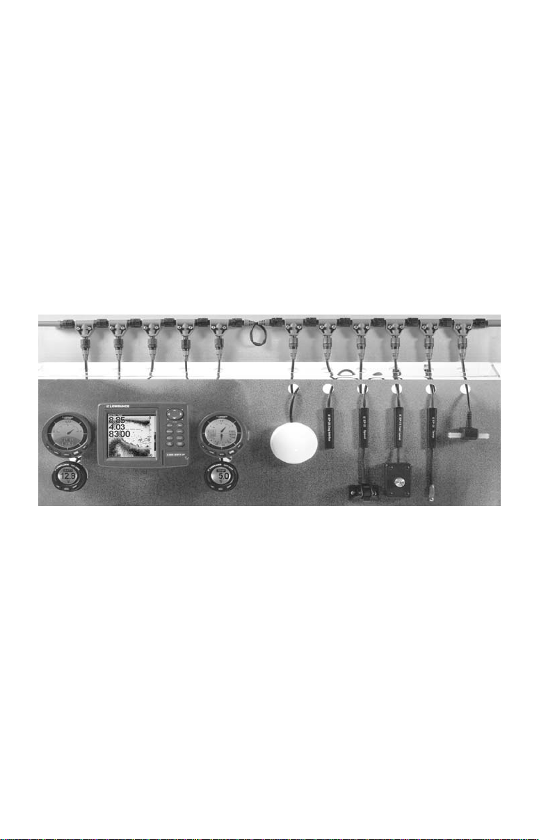
LowranceNET teams up the powerful NMEA 2000 network standard
with a fast-growing, cutting-edge family of Lowrance Electronic Probe
Sensors. At press time, the product line includes the EP-10 Fuel Flow,
EP-15 Fluid Level, EP-20 Engine interface, EP-25 Speed, EP-30 Trim
Tab, EP-35 Temp and EP-45 Water Pressure sensors.
And what's more exciting, there are others on the way! Be sure to log
onto
www.lowrance.com from time to time for the latest developments,
including updated operation manuals and instruction sheets you can
download free of charge. When you're ready to expand your network,
see the accessory ordering information on the back cover of this
manual.
NOTICE!
The storage and operation temperature range for your unit is from
-4 degrees to +167 degrees Fahrenheit (-20 degrees to +75 degrees
Celsius). Extended storage or operation in temperatures higher or
lower than specified will damage the liquid crystal display in your unit.
This type of damage is not covered by the warranty. For more
information, contact the factory's Customer Service Department; phone
numbers are inside the manual's back cover.
4
Section 2: Installation
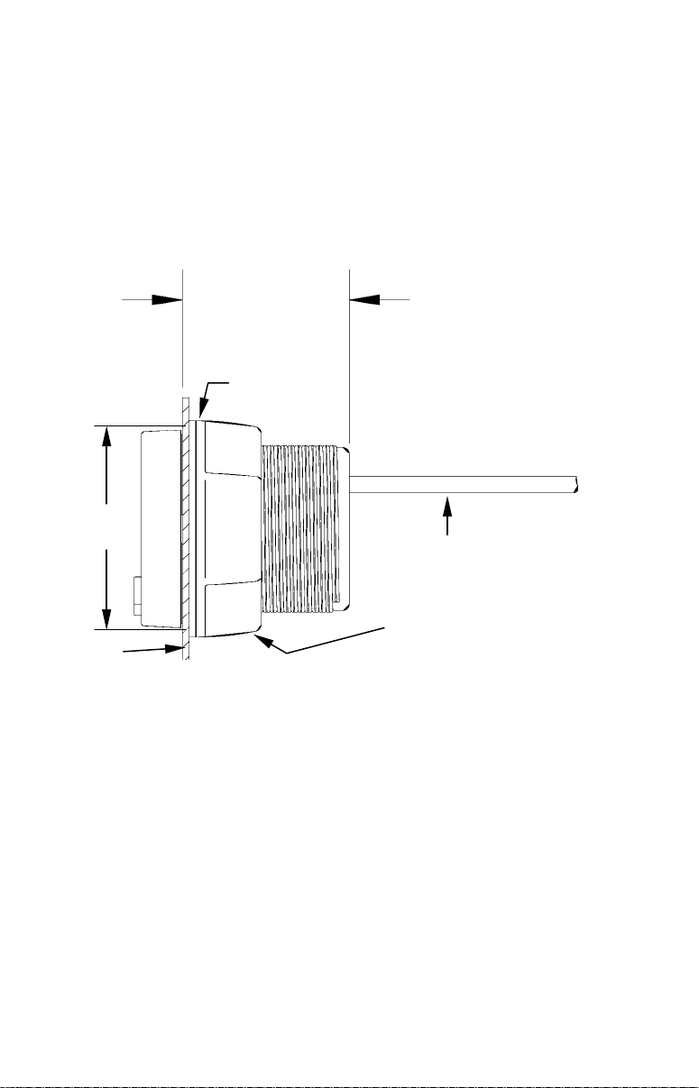
Gasket
Mounting Preparations
When installed, the gauge will cover an area on the dash 2-3/8" (60.3
mm) in diameter. To mount the unit, first make sure there is at least 23/4" (70 mm) from the front of the dash to any obstruction behind the
dash. The maximum usable dash thickness is 1-1/8" (28.5 mm). Also, be
sure there is room to route the network and buzzer cables. The
following figure shows gauge dimensions.
2-3/4"
(70 mm)
2-3/8"
(60.3 mm)
Cables
Threaded mounting collar
Dash
Dash installation, cross-section view.
Caution:
You should read over the entire installation section before
drilling any holes in your vessel!
You can install this gauge in some other order if you prefer, but we
recommend this installation sequence, which is summarized below:
1. Determine the location for the gauge so you can plan how and where
to route the cables. This will help you make sure you have enough cable
length for the desired configuration.
2. Determine the location of the nearest node on the boat's NMEA 2000
network, along with the route of the gauge's network cable.
3. Determine the location for the alarm buzzer and its wire route.
5
4. If you want to turn on the gauge backlights whenever you turn on
your dashboard lights, locate your boat's dash light switch and
determine how to route the dash light wires to it.
5. Install the gauge in the dash.
6. Connect the buzzer wires and install the buzzer. If desired, connect
the dash light wires to the boat's dash light switch.
7. Connect the network cable to the NMEA 2000 network.
Recommended Tools and Supplies
Your LMF-200 packs with a T connector needed to attach it to a
LowranceNET NMEA 2000 network. If you are connecting to an
existing LowranceNET network, those are all the electronic
components you need. If you are creating a new LowranceNET
network, you will also need a one-time purchase of a LowranceNET
Node Kit.
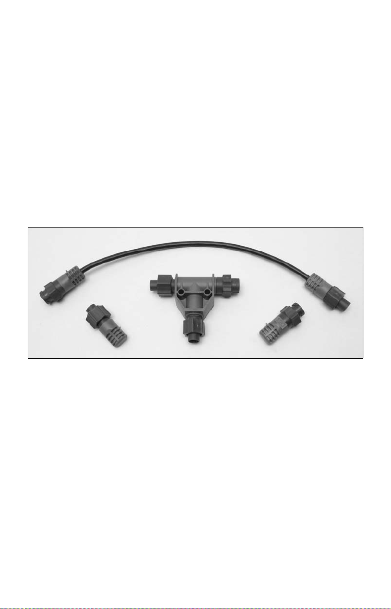
LowranceNET Node Kit for a NMEA 2000 network. Includes a 2 foot
extension cable, T connector, 120-ohm male terminator and 120-ohm
female terminator.
For complete instructions on setting up a new NMEA 2000 network or
expanding an existing one, see the other document packed with your
gauge, "Setup and Installation of NMEA 2000 Networks, General
Information" part number 988-0154-172. If that document is missing, it
can be downloaded free from the Lowrance web site.
Other supplies are not included, unless otherwise indicated. If you need
to route the gauge's network cable connector through a bulkhead, you
will need a drill and a 3/4" drill bit.
If the dash does not have a standard 2-1/8" (54 mm) hole, you will need
a drill or saw to make the hole. Carefully measure the dash thickness
and the hole area before cutting or drilling.
6
The buzzer installation requires two cable ties and two wire nuts or
other wire connectors.
If you need to extend any of the buzzer or dash light wires, use a
minimum of 24 gauge wire and wire connectors of your choice. Wire
nuts or electrical tape are required to cap any unused bare wires.
Mounting the Gauge
When you determine the location for the LMF-200, drill a 2-1/8" (54
mm) hole in the dash or use an existing gauge hole. Slide the unit's
cables through the hole from the front side of the dash, then push the
LMF-200 housing through the hole until it is flush with the dash
surface. Make sure the face of the gauge is aligned correctly.
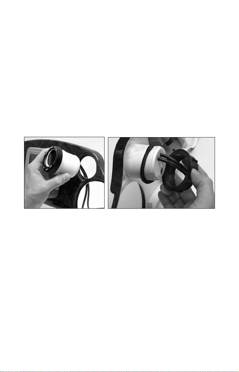
Next, slide the rubber gasket and plastic-mounting collar over the
cables and onto the back side of the gauge.
Insert gauge through the hole in the front side of the dash (left). Slide
the rubber gasket over the cables, followed by the plastic collar (right).
Slide the gasket forward so it is flush with the back of the dash, then
screw on the mounting collar, turning it until it is snug against the
gasket and the back of the dash.
Find a buzzer location that is protected from the elements, but still lets
you hear it. We recommend that you connect the buzzer wires according
to the figure on the following page, then use two cable ties and attach
the buzzer to one or both of the cables at the back of the gauge.
If desired, connect the dash light wires as shown in the following figure.
Finish the installation by plugging the network cable into the network.
Wiring
The LMF-200 draws operating power from the NMEA 2000 network.
The gauge does not have an on/off switch — whenever the network has
power, the LMF-200 is on and drawing current.
7
Ideally, the NMEA 2000 network itself is powered from a switch on the
Buzzer
boat's accessory panel, allowing network power to be turned on and off.
To automatically turn on the gauge backlights when you turn on your
other dashboard lights, connect the red dash light wire to the switch
controlling the dash lights and connect the black dash light wire to
ground.
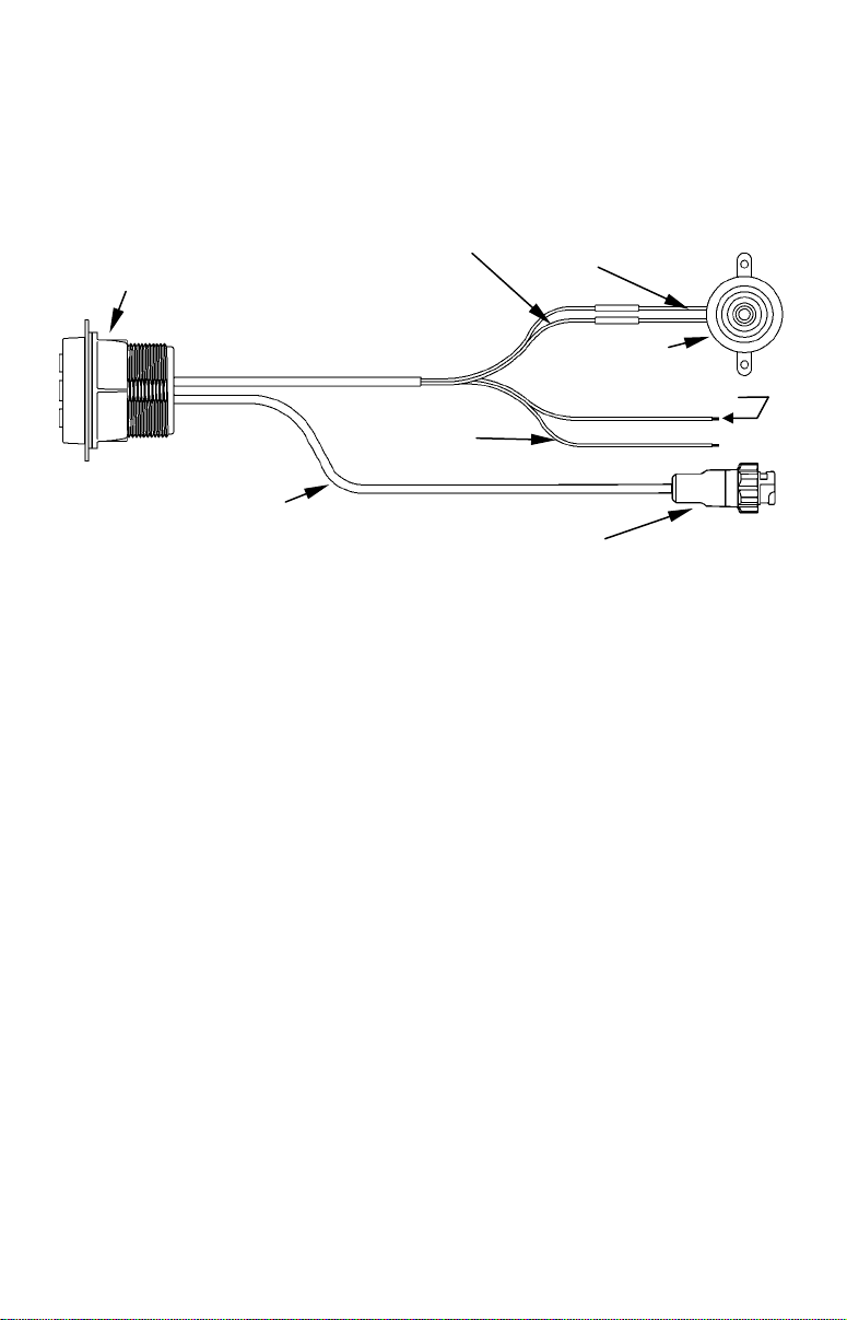
LMF-200 housing
NMEA 2000
Network cable
LMF white wire to
buzzer black wire
Cap unused wires
with wire nuts or tape.
Dash light black
(to ground)
Blue female NMEA
2000 connector
LMF-200 cable connections.
LMF green wire to
buzzer red wire
Dash light red
(to dash light switch)
Caution:
The bare ends on any unused wires could cause an electrical
short if left exposed. To prevent this, you should cover the
individual wire ends — either by capping them with wire nuts
or wrapping them with electrical tape. (You should cut off the
bare wire before taping off the ends.)
Connecting to a NMEA 2000 Network
A network bus is an installed and operational network cable (backbone)
running the length of your boat, already connected to a power supply
and properly terminated. Such a bus provides network connection
nodes at various locations around your boat.
This is similar to the telephone wiring in a house. If you pick up a
phone in your living room, you can hear someone talking into the phone
in the bedroom.
Network Nodes
A network bus is built of network nodes spread along a backbone.
Network nodes are made by fitting T-shaped connectors into the
backbone (using the sockets on the sides), and attaching a display unit or
sensor at the bottom of the "T."
Using our telephone example, the T connectors are similar to telephone
jacks. The backbone is like the phone wiring running through a house.
8
Phones in a house must be connected to each other to communicate, and
in the same way only sensors and display units plugged into the NMEA
network can share information.
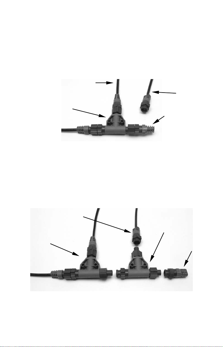
Connections found in the middle of the bus will have one or more of these
T-shaped connectors with the backbone cables plugged into both sides.
Connections at the end of a network will have the backbone plugged into
one side, and a terminator plugged into the other, as shown in the
following figure.
Cable from
sensor or
display unit
LEI or Lowrance
device needs an
open T.
T connector
Backbone cable
(to rest of bus)
NMEA 2000 network node located at the end of a NMEA 2000 bus.
Terminator at
the very end
of the bus
Adding a Network Node
You can add a node anywhere along the network backbone where a
connection already exists. This connection could be at the end of the
network (between a T connector and a terminator), between two T
connectors, between a T connector and a backbone extension cable, or
between two extension cables. Wherever you want to add the new node,
simply separate the sockets of the old connection and attach your new T
connector between them.
Lowrance or LEI device con-
nects to new T connector.
Existing network
node
Add T-shaped connector to add device
to bus.
Attach
terminator at
end of bus.
Add a new device to a NMEA 2000 bus by attaching a T connector
between two T connectors, between a T connector and the end
terminator, or between two backbone extension cables.
9

If you want to add a node at the end of the line (as shown in the previous
figure), remove the terminator from the very last connector, securely
attach the new T connector, and then attach the terminator on the new
connector. Either method will allow you to add a device.
Additional Network Information
Further instructions on creating or expanding a LowranceNET network
are illustrated in the NMEA 2000 network setup booklet, part number
988-0154-172, which came packed with this manual.
10

Section 3: Operation
The displays and settings in this digital gauge are controlled by a
three-button keypad. The buttons are
key calls up the basic menu, which allows you to set up pages for
display. The
menu items.
UP and DOWN keys are used to scroll through and highlight
LMF-200 keypad.
Boat Setup
When the LMF-200 powers up for the first time, the screen will show
the
Boat Setup menu. You will not be able to proceed without
completing boat setup. This will only appear again if you reset values or
if configuration is lost.
To complete Boat Setup:
1. With Boat Setup highlighted on the screen, press
Setup menu will appear, allowing you to choose the number of engines
and fuel tanks on your vessel. The Boat Setup
menu options are: 1 Eng/1 Tank, 1 Eng/2 Tank,
2 Eng/1 Tank, 2 Eng/2 Tanks, 3 Eng/1 Tank or
3 Eng/3 Tanks.
2. Choose the option that applies to your vessel
and press
tank, the Tank Size menu will appear with up
to three options (depending on the number of
tanks chose during Boat Setup): Port Tank, Stbd Tank and Cen Tank.
3. Select the tank you want to set up and press
launch the Tank Size window. If you selected one tank during Boat
Setup, you will be taken directly to the Tank Size Window.
4. Use the
hold and press
more than one tank.
5. After all tanks on your vessel have been set up, you will be directed
to the main display.
MENU. If you chose more than one
UP and DOWN keys to enter how many gallons the tank will
MENU. Press MENU and repeat steps 3 and 4 if you have
UP, DOWN and MENU. The MENU
MENU. The Boat
MENU, which will
11
NOTE:
If your LMF-200 was already installed on your boat you likely will
not have to complete boat setup. But, if you would like to go
through the setup, take a look at the following instructions.
1. Press
RESET.
2. Press
to Reset All Values. Press
factory defaults. The unit then will switch to the Boat
MENU, scroll down to SYSTEM SETUP, then press MENU. Select
MENU, which will launch the following message: Hit Menu
MENU to reset the unit's settings to its
Setup screen.
Pages
Pages are the backbone of the LMF-200. They give you the power to
mix and match data that will be displayed on the screen. Once you have
picked pages that meet your preferences, the 200's multi-functionality
really kicks in, allowing you to customize pages with the data most
important to you. We'll take a closer look at customizing pages in
Section 5: Advanced Operation.
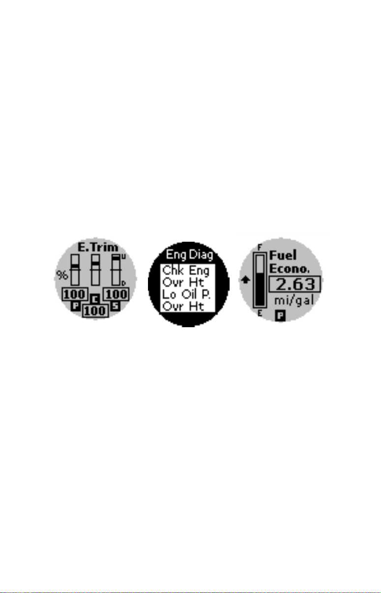
Engine Trim page (left), Engine Diagnotic page (center) and Fuel
Manager page (right).
The LMF-200 allows you to add pages you find most helpful more than
once, customizing each one differently.
Engine Trim
Monitors the position of the boat’s engine through either percentages or
degrees.
Engine Diagnostic
Monitors engine performance, notifying you if a problem arises.
Fuel Manager
The Fuel Manager page has a digital readout capable of displaying:
Fuel Flow (F.Flow), Fuel Economy (F.Econ), Fuel Remaining (F.Rem),
Fuel Range (F.Range), Trip Fuel Used, Seasonal Fuel (Seas.F), Paddle
Wheel Speed (PwSpd), Pitot Speed (PtSpd) and GPS Speed (GpsSpd).
12
 Loading...