

Lowrance Link-6 User Manual
ENGLISH
Link-6
User Guide
lowrance.com

2 |
| Link-6 operator manual
Preface
Disclaimer
As Navico is continuously improving this product, we retain the
right to make changes to the product at any time which may not
be reflected in this version of the manual. Please contact your
nearestdistributor if you require any further assistance.
It is the owner’s sole responsibility to install and use the equipment
in a manner that will not cause accidents, personal injury or
property damage. The user of this product is solely responsible for
observing safe boating practices.
NAVICO HOLDING AS AND ITS SUBSIDIARIES, BRANCHES AND
AFFILIATES DISCLAIM ALL LIABILITY FOR ANY USE OF THIS PRODUCT
IN A WAY THAT MAY CAUSE ACCIDENTS, DAMAGE OR THAT MAY
VIOLATE THE LAW.
Governing Language: This statement, any instruction manuals,
user guides and other information relating to the product
(Documentation) may be translated to, or has been translated from,
another language (Translation). In the event of any conflict between
any Translation of the Documentation, the English language
version of the Documentation will be the official version of the
Documentation.
This manual represents the product as at the time of printing.
Navico Holding AS and its subsidiaries, branches and affiliates
reserve the right to make changes to specifications without notice.
Copyright
Copyright © 2017 Navico Holding AS.
Warranty
The warranty card is supplied as a separate document.
In case of any queries, refer to the brand website of your unit or
system: www.lowrance.com
RF Emissions notice
This equipment complies with FCC radiation exposure limits set
forth for an uncontrolled environment. This device’s antenna must
be installed in accordance with provided instructions; and it must
be operated with minimum 1.8 m spacing between the antennas
and all person’s body (excluding extremities of hands, wrist and feet)

| 3
| Link-6 operator manual
during operation. Further, this transmitter must not be co-located or
operated in conjunction with any other antenna or transmitter.
FCC Statement
This device complies with Part 15 of the FCC Rules. Operation
is subject to the following two conditions: (1) this device may
not cause harmful interference, and (2) this device must accept
any interference received, including interference that may cause
undesired operation.
¼ Note: This equipment has been tested and found to comply with
the limits for a Class B digital device, pursuant to Part 15 of the FCC
Rules. These limits are designed to provide reasonable protection
against harmful interference in a normal installation. This equipment
generates, uses and can radiate radio frequency energy and, if not
installed and used in accordance with the instructions, may cause
harmful interference to radio communications. However, there is no
guarantee that interference will not occur in a particular installation.
If this equipment does cause harmful interference to radio or television reception, which can be determined by turning the equipment
off and on, the user is encouraged to try to correct the interference
by one or more of the following measures:
Reorient or relocate the receiving antenna.
Increase the separation between the equipment and receiver.
Connect the equipment into an output on a circuit different
from that to which the receiver is connected.
Consult the dealer or an experienced technician for help.
A shielded cable must be used when connecting a peripheral to
the serial ports.
Innovation, Science and Economic
Development Canada Compliance
This equipment complies with ISEDC RF radiation exposure limits
set forth for an uncontrolled environment. This transmitter must not
be co-located or operating in conjunction with any other antenna
or transmitter. This equipment should be installed and operated
with minimum distance 1.8m between the radiator & your body.
ISEDC exposition aux radiations:
Cet équipement est conforme avec ISEDC les limites d’exposition
aux rayonnements définies pour un contrôlé environnement.
Cet émetteur ne doit pas être co-localisés ou fonctionner en

4 |
| Link-6 operator manual
conjonction avec une autre antenne ou émetteur.
Cet équipement doit être installé et utilisé avec un minimum de 1.8
m de distance entre le radiateur et votre corps.
CE Compliance Statement
This product complies with CE under RED directive 2014/53/EU.
The relevant Declaration of Conformity is available in the following
website under model documentation section:
http://www.lowrance.com
Warning
The user is cautioned that any changes or modifications not
expressly approved by the party responsible for compliance could
void the user’s authority to operate the equipment. This equipment
generates, uses and can radiate radio frequency energy and, if not
installed and used in accordance with the instructions, may cause
harmful interference to radio communications. However, there is
no guarantee that the interference will not occur in a particular
installation. If this equipment does cause harmful interference to
radio or television reception, which can be determined by turning
the equipment off and on, the user is encouraged to try to correct
the interference by one or more of the following measures:
• Reorient or relocate the receiving antenna
• Increase the separation between the equipment and receiver
• Connect the equipment into an outlet on a circuit different from
that of the receiver
• Consult the dealer or an experienced technician for help

| 5
| Link-6 operator manual
Countries of intended use in the EU
AT - Austria HU - Hungary PL - Poland
BE - Belgium IS - Iceland PT - Portugal
BG - Bulgaria IE - Ireland RO - Romania
CY - Cyprus IT - Italy SK - Slovak Republic
CZ - Czech Republic LV - Latvia SI - Slovenia
DK - Denmark LI - Liechtenstein ES - Spain
EE - Estonia LT - Lithuania SE - Sweden
FI - Finland LU - Luxembourg CH - Switzerland
FR - France MT - Malta TR - Turkey
DE - Germany NL - Netherlands UK - United Kingdom
GR - Greece NO - Norway
Trademarks
Lowrance® and Navico® are registered trademarks of Navico.
NMEA® and NMEA 2000® are registered trademarks of the National
Marine Electronics Association.
Navico recommends that you check the radio operating licensing
requirements of your country before using this VHF radio. The
operator is solely responsible for observing proper radio installation
and usage practices.
Notes on MMSI and DSC
The user MMSI (Marine Mobile Service Identity) is a unique nine
digit number. It is used on marine transceivers that are capable of
using DSC (Digital Selective Calling). Digital Selective Calling offers
significant safety and convenience advantages over older VHF radios
without this functionality.
¼ Note: many countries do not have radio repeaters that support DSC
message relaying. However DSC can still be useful for direct ship-toship communication, where the other vessel is also equiped with a
DSC capable radio.
You must obtain a user MMSI and enter it into your radio in order to
use the DSC functions. Contact the appropriate authorities in your
country to obtain an MMSI number - charges may apply. If you are
unsure who to contact, consult your Lowrance dealer.

6 |
| Link-6 operator manual
¼ Note: DSC distress calls generated by this radio are limited to the
same range restrictions that apply to regular VHF transmissions. The
vessel sending a distress can only rely upon DSC if within range of a
GMDSS Coast Radio Station. Typical VHF range may be about 20NM,
though this varies greatly depending upon installation, antenna
type, meteorological conditions, etc.
About this manual
This manual is a reference guide for installing and operating a Link-6
VHF radio. Important text that requires special attention from the
reader is emphasized as follows:
¼ Note: Used to draw the reader’s attention to a comment or some
important information.
Warning: Used when it is necessary to warn personnel that
they should proceed carefully to prevent risk of injury and/or
damage to equipment/personnel.
!

| 7
Contents | Link-6 operator manual
Contents
8 General Information
9 How to display and navigate menus
12 Key functions
15 The radio menus
15 Scan menu
16 Watch
17 Display
17 Radio setup
20 DSC setup
22 Alarms
23 Reset
24 DSC call menu
24 DSC calls
26 Track buddy
27 Contacts
29 My channels
30 Shortcuts
31 Installation
31 Checklist
32 Installation options
32 Selecting a suitable mounting location
36 First startup configuration
39 Specications
42 Channel charts
42 EU and INTERNATIONAL channel chart
50 USA channel chart
52 CANADA channel chart
55 Dimensional drawings

8 |
General Information | Link-6 operator manual
General Information
Your Link-6 provides the following useful features:
• Prominent channel display
• Adjustable contrast settings for the LCD
• Adjustable keypad backlighting for easy night-time use
• Waterproof and submersible to comply with IPx7
• GPS latitude and longitude (LL) and time display (when connected
to a GPS source)
• Choice of High (25 W) or Low (1 W) transmission power
• 4 key handset mic with built-in speaker
• Powerful 4 W external audio output
• Access to all currently-available marine VHF channel banks (USA,
Canada, International) including weather channels where available
(model dependant)
• Dedicated CH16/9 key for quick access to the priority (international
distress) channel
• TRI key to select DUAL/TRI scan
• Dedicated Wx (Weather) key
• DSC (Digital Selective Calling) capability that meets Global DSC
Class D Standards
• Separate CH70 receiver included built in
• DISTRESS call button to automatically transmit the MMSI and
position until an acknowledgement is received
• Contacts list that stores up to 50 names with MMSI numbers
• MMSI storage for three favourite groups
• Group Call and All Ships Call facility
• LL position polling information
• Weather alert facility where available (US mode)
• ATIS facility for inland waterways (EU mode)
• With DSC Auto-Switch disable and DSC Test function
1
| 9
General Information | Link-6 operator manual
How to display and navigate menus
The majority of the buttons, and both of the rotary knobs, can open
menus with multiple options.
The channel knob is used to scroll through the options. The
currently selected option is indicated by a black highlight bar, and
the text is inverted to white.
Selection of a highlighted option is made by pressing the channel
knob.
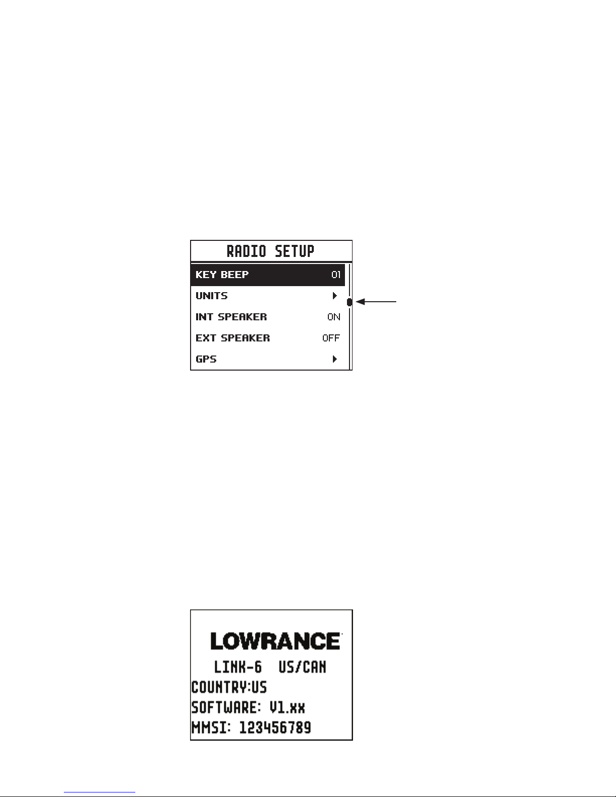
If a list of options is too long for the page, a scroll bar is shown on
the right side of the screen. The black rectangle on the scroll bar
indicates the highlighted options relative position in the list.
Press the Exit button to step backwards to the previous menu page,
or exit the menus completely.
Entry of alphanumeric data
Rotate the channel knob to scroll through the alphanumeric
characters.
Press channel knob, to select and step to the next character.
To step backwards, press the MENU button. Press X to cancel entry
and return to previous menu.
LCD symbols and meanings
When the Link-6 starts up it momentarily displays the brand, model,
region, software version, and MMSI.
scroll bar indicates further
options above and below
displayed text
10 |
General Information | Link-6 operator manual
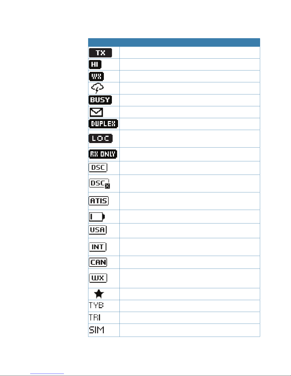
During normal operation, the following icons may be displayed on
the screen depending on setup:
Symbol Meaning
Transmitting
Transmition power
Weather channel stored by user (EU/INT only)
Weather alert enabled
Receiver Busy with incoming signal
Missed DSC call
Duplex channel selected (off when Simplex)
Local mode enabled (used when in areas of high radio
traffic, ie inner harbour)
Channel can only be received on
DSC functionality is enabled
DSC functionality is enabled, auto switching is turned
off
EU models only - must be enabled when in European
inland waterways
Low Battery warning (activates at 10.5 V)
Channel bank is set to USA
Channel bank is set to International. (Channels
available depends on country radio cloned for)
Channel bank is set to Canada
Weather channel bank active (USA/CAN) replaces
channelbank icon temporarily
Channel is saved in the MY CHANNELS list
Track your Buddy feature is active
TRI watch or DUAL scan is active
GPS simulator is active
| 11
General Information | Link-6 operator manual
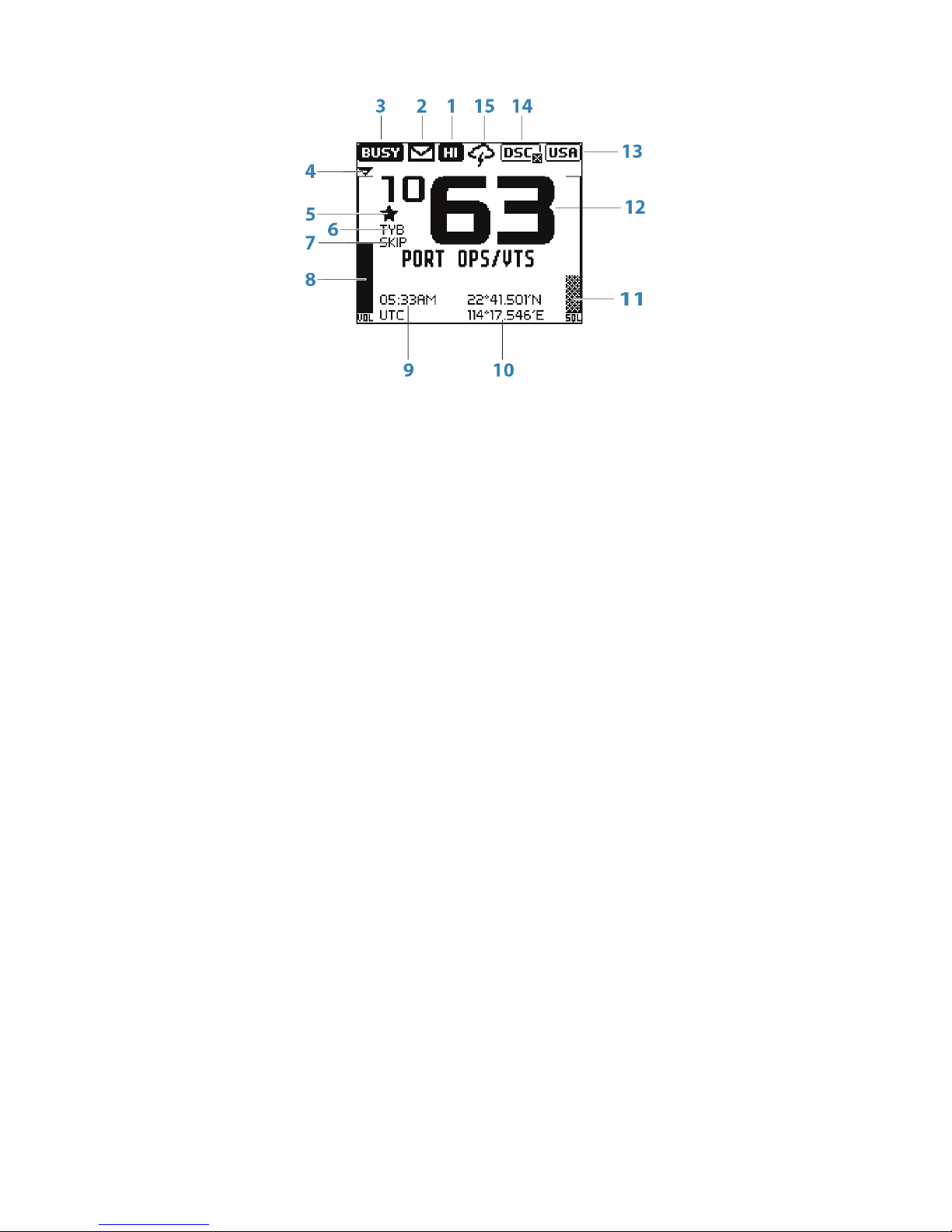
A typical display:
1. Channel is set to high power transmit
2. Missed call in the DSC call log
3. Channel is busy
4. Volume is under active control
5. Current channel saved in ‘My Channels’
6. Track your buddy is enabled
7. Current channel will be skipped during a scan
8. Volume level indicator
9. Time (derived from GPS) - UTC offset is applied
10. Latitude/Longitude
11. Squelch level indicator
12. Channel number (2 or 4 digits)
13. The USA channel bank is active
14. DSC functionality is enabled, but autoswitch is off
15. Weather alert function is enabled
12 |
General Information | Link-6 operator manual
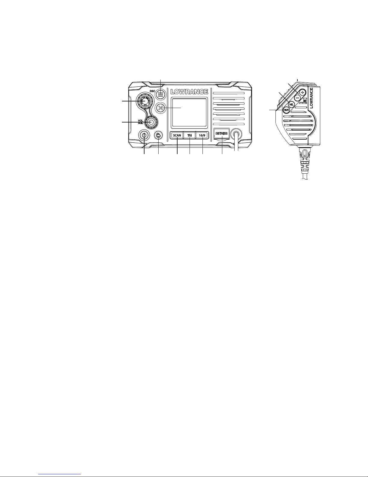
Key functions
The following describes the direct functions of the keys/knobs.
Where necessary, additional detail on any menus accessed by keys is
covered in following chapters.
1
2
3
4
5 6 7 8 9 10
9
11
12
13
1. Channel knob / Press to Select
Turn knob for channel selection, menu scrolling, alphanumeric entry, and
fine adjustment of backlight level (dependent on active menu).
Short press to make selections in menus.
Long press to open MY CHANNELS.
2. VOL / SQL
Volume and Squelch level.
Short press knob to select which control to adjust. Which is currently
selected is indicated by a small triangular arrow above the level bar for
each option. Turning the knob clockwise increases setting, anti-clockwise
decreases it. Volume control is common to internal and external speaker.
Long press to open SHORTCUTS.
3. EXIT
Press EXIT when navigating menus, to clear incorrect entries, to exit from a
menu without saving changes, and to back up to the previous screen.
4. DSC CALL / MENU SELECT
Short press to enter the DSC Call Menu and make DSC calls.
Long press to open the MENU SELECT page.
5. Power / Backlight
Short Press to adjust backlight level sequentally.
Repeated short press of the power button will step through large backlight
adjustments. The Channel knob can be used to make finer adjustments.
Long press to turn radio on or off.
6. Weather Channel
Short press (US/CAN models): press to hear the most recently selected
NOAA/Canadian weather station.
For all other models, changes channel to user programmed choice.
Long press (non US/CAN models only): to store current channel as the

| 13
General Information | Link-6 operator manual
weather channel.
7. SCAN
Short press to enter ALL SCAN mode.
ALL SCAN sequentially scans all channels for activity.
When a signal is received, scanning stops at that channel and the BUSY icon
appears on the screen. If the signal ceases for more than 5 seconds, the
scan automatically resumes.
Turn the channel knob to temporarily skip over (lock out) a busy channel
and resume the scan. The direction turned determines if the scan goes
up or down the channel numbers (ie ‘forward’ or ‘reverse’). If it is still busy
when the scan completes a full cycle, it will stop again at this channel. Note
that it is not possible to skip over the priority channel.
Press ENT to permanently skip over the channel. The SKIP icon will show on
the LCD for this channel.
To cancel a skipped channel, select the channel while in normal mode
(non-scan mode) then press the ENT key - the SKIP icon will disappear.
Repowering the radio also restores all skipped channels.
Press SCAN or EXIT while scanning is active to stop at the current channel
and return to normal operation.
Long press SCAN from normal operation to enter the SCAN menu.
8. TRI (WATCH)
Short press to start DUAL WATCH or TRI WATCH (if ‘watch’ channel set)
Long press to set the current channel as the watch channel.
When a short press is made on the TRI key, the radio will either switch to
DUAL or TRI watch mode depending on whether a watch channel has
been setup.
Without a watch channel the radio will go to DUAL WATCH, where the
channels ‘watched’ are the current channel and the priority channel (the
distress channel, CH16 for most countries).
With a watch channel selected, TRI WATCH is enabled, where the channels
‘watched’ are the current channel the ‘watch’ channel, and the priority
channel (the distress channel, CH16 for most countries).
If the radio is set to ‘Country: USA’, two priority channels are watched Channel 9 and Channel 16.
9. 16 / 9 (radio and handset)
Short press to change to priority channel. Press again to return to original
channel.
For US models: Long press to make Channel 09 the priority channel.
The default Priority Channel is CH16.
10. DISTRESS
Short press to start a distress call, where the nature of distress can be
selected from a list.
Long press the distress button to initiate an ‘undesignated’ distress call.
This call is broadcast to all DSC equipped radios, so will create an alarm on
every DSC radio within range.
If position information is available it will be included in the transmition.

14 |
General Information | Link-6 operator manual
11. H/L (handset mic only)
Transmission Power.
Press to toggle between high (25 W) or low (1 W) transmission power for
the entire channel bank. The HI or LO selection is shown on the LCD.
Some channels allow only low power transmissions. Error beeps will sound
if attempting to change the transmission power while on one of these
channels.
Some channels allow only low power transmissions initially, but can be
overridden to high power by pressing (and holding) H/L after depressing
PTT. Keep the H/L button pressed down after releasing the PTT button, if
wanting to transmit again on high power.
12. + / - (handset mic only)
Channel change.
Short press (+) goes up one channel, or (-) goes down one channel.
Holding either key will, after a short delay, step rapidly through the
channels.
13. PTT (handset mic only)
Push-to-talk button.
Press button to transmit. Only depress for duration of message to be
broadcast. Radio can’t receive while it is transmitting.

| 15
The radio menus | Link-6 operator manual
The radio menus
A long press of the MENU button opens MENU SELECT page. The
following shows the menu structure (top and 2nd level only):
ALL SCAN
ALL CHANNELS + 16
MY CHANNELS
MY CHANNELS + 16
EDIT MY CHANNELS (choose channels)
DUAL WATCH
TRI WATCH
SET WATCH CHANNEL (choose channel)
TIME DISPLAY (ON / OFF)
POS DISPLAY (ON / OFF)
COG/SOG (ON / OFF)
BACKLIGHT (OFF, 1-10)
CONTRAST (0-10)
SENSITIVITY (DISTANT/LOCAL)
UIC (USA/INT’L/CANADA)
POWER OUTPUT (HIGH/LOW)
CH NAME (>)
KEY BEEP (0-10)
UNITS (>)
INT SPEAKER (ON/OFF)
EXT SPEAKER (ON/OFF)
GPS (>)
TIME (>)
VESSEL CALLSIGN (>)
MENU TIMEOUT (>)
DSC FUNCTION (X)
USER MMSI (>)
ATIS FUNCTION (ON/OFF)
SEA/INLAND USE (SEA/INLAND)
ATIS MMSI (>)
INDIVIDUAL ACKN. (AUTO/MANUAL)
POS ACKNOWLEDGE (>)
AUTO SWITCH (ON/OFF)
TEST ACKNOWLEDGE (AUTO/MANUAL)
RX DISTR WHILE OFF ( X)
DSC TIMEOUT (>)
WATC H
DISPLAY
SCAN
RADIO SETUP
DSC SETUP
ALARMS
GPS ALERT (>)
WX ALERT (>)
DSC ALARM (>)
RESET
(EU cloned radio only)
(EU cloned radio only)
(EU cloned radio only)
(US cloned radio only)
(YES/CANCEL)
Key:
(>) further menu options
(X) toggle selection. ‘X’ means option enabled.
Scan menu
This menu is for choosing a scan mode to enable, as well as
selection of the channels scanned per the MY CHANNELS list.
¼ Note: Scanning is not available if ATIS mode is turned on.
All scan
Scans all channels cyclically.
All channels + 16
Scans all channels cyclically, but checks the priority channel after
every channel step
2
16 |
The radio menus | Link-6 operator manual
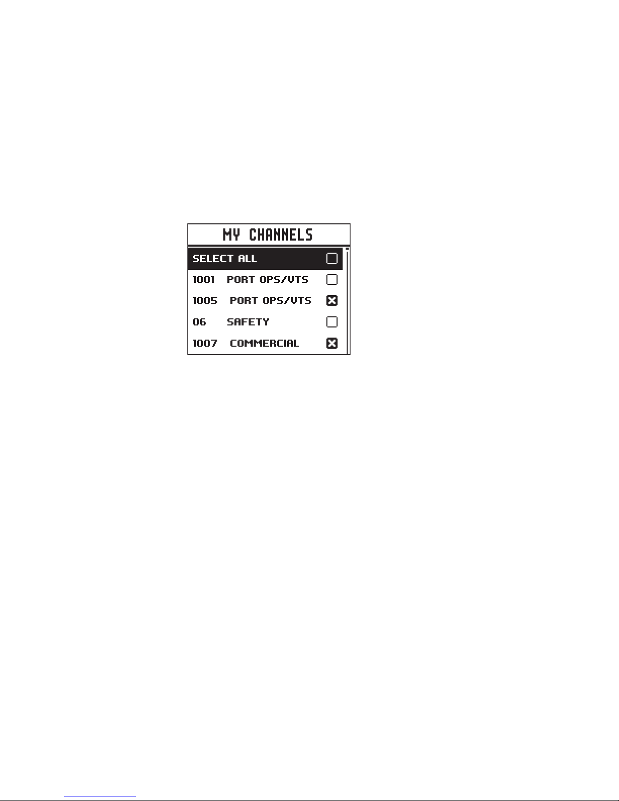
My channels
Scan all channels selected in EDIT MY CHANNELS
My channels + 16
Scans all channels selected in EDIT MY CHANNELS, while also
checking the priority channel after every channel step.
Edit my channels
Allows creation of a custom list of channels - used in a MY
CHANNELS scan.
Watch
This menu is for choosing a watch mode to enable, as well as
selection of the watch channel. Watch modes can be thought of as
a channel scan on a subset of channels, where scanned channels
are ‘listened’ to briefly every 3 seconds, to determine if there is any
active radio communication.
¼ Note: Watch modes are not available if ATIS mode is turned on.
Dual watch
Select this to watch the current channel and the priority channel
(Channel 16).
TRI watch
Select this to watch the current channel, the user selected ‘watch’
channel, and the priority channel (Channel 16).
Set Watch Channel
Allows a watch channel to be selected from all available channels.
Selected channel is used by TRI WATCH mode.
¼ Note: If the radio is configured for USA market, two priority channels
are watched: Channel 9 and Channel 16.

| 17
The radio menus | Link-6 operator manual
Display
This menu allows the user to partially customize the screen
information displayed, and adjust the screen for best visibility to suit
the user and operating conditions.
Time display
Select to switch the display of Time to ON or OFF.
If turned ON, the display of COG/SOG is turned off, due to screen
space constraints.
LOC (Local Time) is displayed below the time if a UTC (Coordinated
Universal Time) offset has been entered; otherwise UTC is shown in
it’s place if no offset has been applied.
POS display
Select to switch ON or OFF the display of position provided from
connected GPS.
COG/SOG
Select to switch ON or OFF the display of COG/SOG provided from
connected GPS.
If turned ON, Time display is turned OFF, due to screen space
constraints.
Backlight
Select to make adjustment to the backlight level using the Channel
knob. Range is OFF, then 1 to 10.
Press MENU SELECT button to activate night mode (inverts display).
Contrast
Select to make adjustment of the screens contrast, using the
Channel knob. Range is 00 to 10.
Radio setup
The Radio setup menu covers settings that are typically configured
at installation, and seldom need changing.
Local/Dist
Use LOCAL/DIST to improve the sensitivity of the receiver either
locally (LOCAL) or over distances (DIST).
LOCAL is not recommended for use in open sea conditions. It is

18 |
The radio menus | Link-6 operator manual
designed for use in areas of high radio noise; for example, close to a
busy port or city.
UIC
Select between USA, International or Canadian channel banks. The
selected channel bank is displayed on the LCD along with the last
used channel. All the channel charts are shown in “Channel charts”
on page 42.
¼ Note: UIC may not be available on all models.
Power output
Select to toggle between high (25 W) or low (1 W) transmission
power for the entire channel bank. The HI or LO selection is shown
on the LCD. Low power transmission draws significantly less current
(about 1/4) from the battery, so is recommended for short range
communication, and where battery capacity is limited.
¼ Note: some channels can’t be switched to high power, and will
show LO regardless of power output setting in menu.
CH name
CH NAME gives you the option to edit or delete the channel name
descriptions displayed on the screen.
Select to edit the existing description of the channel currently in
use. It can be a maximum of 12 characters long.
Key beep
Select to allow adjustment of key beep volume.
Volume can be set from 00 - 10 (where 00 is off, and 10 is loudest).
Units
Select SPEED to choose whether displayed in KNOTS, MPH, or KPH
Select COURSE to toggle between displaying in MAGNETIC or TRUE.
A true north heading is corrected for magnetic declination. A
magnetic north heading source must also output magnetic
variation data if the heading is to be displayed as a true north value.
Int speaker
Select to switch the radio’s internal speaker ON or OFF.
Incoming voice calls and audible DSC alerts are prevented, but key
beeps and alarms will still be audible.
 Loading...