

™
Pub. 988-0154-651
LGC-3000, LGC-Baja
GPS Modules
Installation Instructions
This instruction sheet tells how to install your LGC-3000 or LGC-Baja
GPS module and connect it to a NMEA 2000
LowranceNET™ network components.
The LGC-Baja is a ruggedized module designed to withstand the rigors of offroad automobile racing. It works just like the LGC-3000, and for simplicity
we will only refer to the LGC-3000 in the rest of this instruction sheet.
The LGC-3000 GPS module, like the other Lowrance Electronic Probe
(EP) sensors, is designed only for use with a NMEA 2000 Network. It
MUST be connected to a NMEA 2000 network or it WILL NOT function.
CAUTION:
Installing LowranceNET NMEA 2000 devices is significantly
different from installing earlier Lowrance components without
NMEA 2000 features. You should read all of the installation instructions before proceeding. You should decide where to install
all components before drilling any holes in your vessel or vehicle.
Some sonar or GPS display units may require: 1. a software upgrade to
display NMEA 2000 data correctly; and 2. a manual addendum describing how to operate the sensor. You can download these free and get additional information on the NMEA 2000
system at our web site, www.lowrance.com.
®
compatible LowranceNET™
®
network using
All Lowrance NMEA 2000 capable devices are either NMEA 2000 certified or certification is pending. See our web site for the latest product
status information.
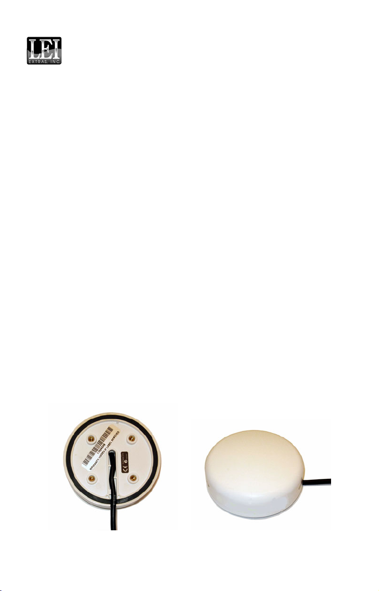
LGC-3000 Module, bottom view (left) and top view (right).
1
The LGC-3000 consists of a red male threaded cable connector and the
GPS module. The GPS module contains a 12-parallel channel GPS+WAAS
receiver. The cable length from the connector to the GPS module is 18
inches (45.7 cm).
The module packs with: a 15 foot (4.6 m) extension cable with a male
connector on one end and a female connector on the other end; one red
network T connector; as well as the parts needed for mounting the module on a flat surface or the optional pole mount.
Some packages may include the QM-1 quick mount bracket, which is also
available as an option. (The QM-1 includes its own instruction sheet, part
988-0154-502.) The QM-1 is a quick-connecting, bayonet-style mounting device. It is designed so you can easily mount and dismount any antenna module similar to the LGC-3000, LGC-Baja, LGC-2000, LGC-12W or EGC-12W.
An optional marine pole mount and optional magnet for temporary
mounting on any ferrous metal surface are also available. For ordering
information, see the end of this instruction sheet.
Tools and Supplies
Other supplies are not included, unless otherwise indicated. Recommended tools are pliers and a flathead screwdriver. If you need to route
the module connector through a bulkhead, you will need a drill and a
7/8" (22 mm) drill bit. If you are mounting the module directly to a console or similar surface, you will need a 3/16" (4.75 mm) drill bit for the
screw holes.
If you wish to add additional NMEA 2000 sensors or more than one display
unit, you may need a one-time purchase of a LowranceNET Node Kit.
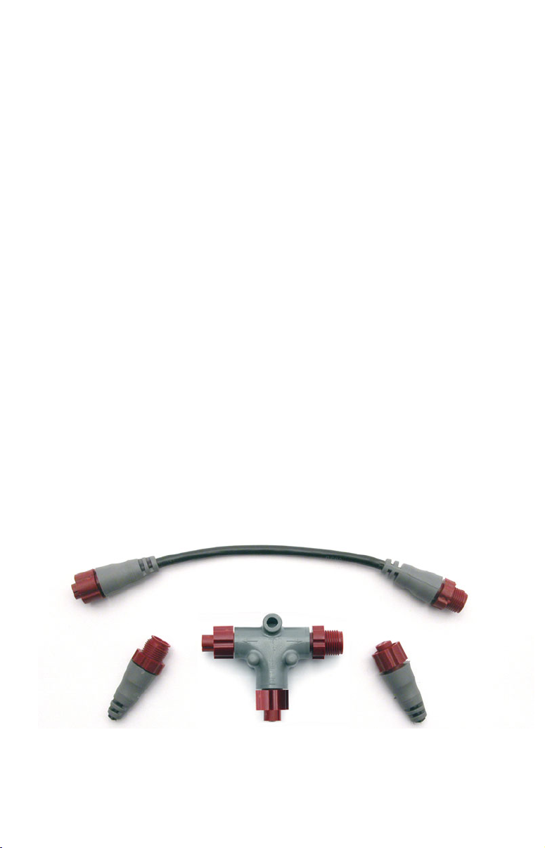
LowranceNET Node Kit for a NMEA 2000 network. Includes a 2 foot (61
cm) extension cable, T connector, 120-ohm male terminator and 120-
ohm female terminator.
2

For complete instructions on setting up a new NMEA 2000 network or
expanding an existing one, see the other document packed with your
LGC-3000 GPS module, "Setup and Installation of NMEA 2000 Net-
works, General Information," part number 988-0154-173. If that document is missing, it can be downloaded free from the Lowrance web site.
Mounting
The GPS module can be mounted on any flat surface, provided there is
access behind the mounting surface for the screws. The optional magnet allows the module to be easily used on cars or off-road vehicles. The
optional pole mount adapter lets you mount the antenna on a pole or
swivel mount that uses standard marine 1"-14 threads.
Surface Mount
The GPS module can be easily installed on any flat surface that is at
least 3-1/2" (90 mm) wide. Be sure that a clear, unobstructed view of
the sky is available at the selected location. GPS signals travel "line-ofsight" at very high frequencies, so nearly anything blocking the antenna can stop the unit from finding a satellite.
Caution:
Do not mount the GPS module in the direct path of a radar antenna's beam. Radar radiates high-energy signals that can interfere with GPS signal reception.
In an automobile, you may achieve good reception by simply placing the
external antenna on the top of the dash, at the base of the windshield. A
piece of the rubber non-skid shelf liner material available in recreational vehicle supply stores will help hold the antenna in place. This
may not work well if you have a cab-over design pickup truck camper or
motor home. If dashboard reception is poor, simply relocate the antenna
module elsewhere on the vehicle for a clearer view of the sky.
Once you’ve determined the mounting location, use the template on the
following page to drill the screw holes. The screws supplied with this
unit are about 1-1/8" long (4 mm x 30 mm). Drill 3/16" (4.75 mm) holes
for the mounting screws.
If you need to route the cable through the mounting surface, drill a 7/8"
(22 mm) hole for the cable's connector. The notch in the antenna housing allows the cable to pass through, if desired, instead of routing it
down through the mounting surface.
After drilling the holes, pass the O-ring over the cable and press it into
the groove on the bottom of the antenna housing. (If you are using the
housing notch to route the cable outside, you may need to cut a notch in
3
the O-ring for a proper fit.) Now attach the antenna to the mounting
surface, using the supplied 4 mm screws and the lock washers. Route
the cable to where it connects to the network and plug it in. The GPS
module installation is finished.
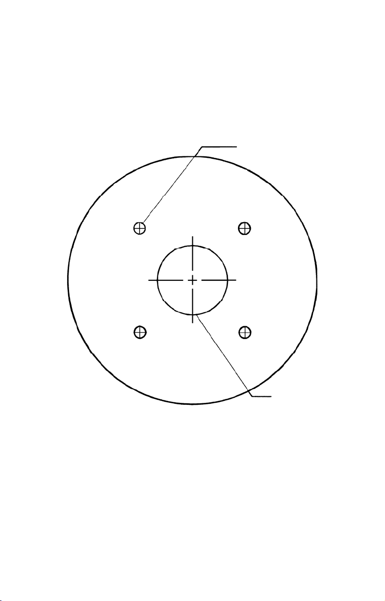
Drill size 3/16" (4.75 mm)
Drill four places.
Drill size 7/8"
(22 mm ) if needed.
GPS module mounting template.
4
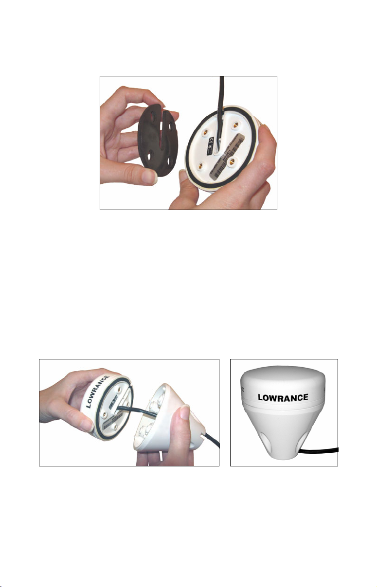
Magnet Mount
The optional magnet lets you temporarily mount the GPS module on any
ferrous metal surface, such as a car roof.
Under side view showing where to place the magnet.
To use the magnet, simply peel the backing off the magnet's adhesive
coating and press the magnet to the bottom of the antenna housing. The
module is ready for use.
Pole Mount
The GPS module attaches to the optional pole mount adapter with the
supplied 4 mm screws. You can route the cable through the notch in the
module housing and down the side of the pole. Or, you can pass it down
through the pole mount adapter and run the cable inside the pole. The 1"14 threads on the pole mount adapter fit a standard marine antenna
mounting pole.
Pole Mount.
Power Connections
The display unit that you will use with the GPS module came with a
power/data cable that splits into three branches, each with several ex-
5

posed wires. Depending on your configuration, this three-branched cable could be the power source for the GPS module.
The thicker two-wire cable branch (red and black) is the power supply
for the display unit. This cable has no label.
The cable branch with three wires (red, black and shield) is the power
cable for a NMEA 2000 network. It is labeled "NMEA 2000 POWER."
Typically, this branch is used to power the GPS module.
The branch with 5 wires (blue, yellow, orange, green and shield) is a
data cable, labeled "RS-232 COMM." This allows your display unit to
exchange NMEA 0183 data with another device, such as an autopilot,
DSC marine radio or computer.
Display unit power wires:
red and black
To unit
NMEA 2000 power wires:
red, black and shield
Data cable wires: blue,
yellow, orange, green
The Power/Data cable for the display unit used with the GPS module.
and shield
NOTE:
There are two basic power connection options, which are shown in
the two diagrams on pages 7 and 8. Read the following instruc-
tions carefully to determine which power connection applies
to your display unit and GPS module. Depending on your con-
figuration, you may not use all of these wires.
Caution:
All wires in the power/data cable have bare ends for easier installation. The bare ends on any unused wires should be capped
with wire nuts or electrical tape to prevent an electrical short.
Powering Your Display Unit
Complete instructions for powering the display unit are in the unit's
manual. Attach the display power cable (with provided 3-amp fuse) to a
12-volt DC accessory switch or power bus. The display unit power cable
is shown connected to power in both Diagram A (page 7) and Diagram
B (page 8).
6

WARNING:
p
The display unit must be independently fused with the
enclosed 3-amp fuse (or equivalent), even if you connect
to a fused accessory or power bus. Failure to use a 3-amp
fuse will void your warranty.
Powering Your GPS Module
A NMEA 2000 network bus must be connected to a power source to operate. NMEA 2000 devices, including the LGC-3000 GPS module, draw
their power from the network bus.
The network and any NMEA 2000 devices, including the LGC3000 GPS module, will not operate
unless the NMEA 2000 net-
work is powered. This is shown in Power Diagram A below. The
NMEA 2000 power cable must be connected to power even if your only
NMEA 2000 device is the GPS module. (A display unit and a GPS module form a simple NMEA 2000 network.) However, never connect
multiple power sources to a NMEA 2000 network. If you have a
network that is already powered, see diagram B on page 8.
Power Diagram A
To display unit
Mandatory
network
power-off
switch
NMEA 2000
Power Cable
3-amp fuse
Shield
Display Unit
Power Cable
Recommended
display unit
ower-off switch
Data Cable
Use this method if you are powering the display unit and NMEA 2000
3-amp fuse
Black
network.
Black
Red
12 volt DC
power source
7

Power Diagram B
To display unit
Red wire with
3-amp fuse
Display Unit
Power Cable
All unused
Data or NMEA
2000 power
wires should
be capped
with wire nuts
and electrical
tape to prevent
Data Cable
Use this method if you are only powering your display unit and are not
powering a NMEA 2000 network or any NMEA 2000 accessory device,
NMEA 2000 Power Cable
Recommended
power off switch
including a GPS module.
Black wire
12 volt DC
power source
The method in diagram B is also used when your display unit is connected to a NMEA 2000 network that is already connected to power.
(Never connect multiple power sources to a NMEA 2000 network.)
Powering a NMEA 2000 Network Bus
If you have a pre-existing NMEA 2000 network installation, it may already be connected to another power source. If you are not sure about a
network's power status, consult the boat manufacturer or dealer. If your
NMEA 2000 bus is already powered, you do not need to connect the
NMEA 2000 Power cable. You can connect the LGC-3000 directly to the
display unit or anywhere along the network and it will operate. Never
attach two power sources to a single NMEA 2000 bus.
If you do need to power your NMEA 2000 bus, attach the NMEA 2000 Power
cable to an accessory switch as indicated in Power Diagram A on page 7. The
NMEA 2000 Power cable's red wire should be attached (with provided 3-amp
fuse) to the positive (+) terminal. The NMEA 2000 Power cable's black and
shield wires should both be attached to the negative (–) terminal.
8

WARNING:
Many devices on a powered NMEA 2000 network bus are
always on and constantly drawing power. This includes a
simple network composed only of a display unit and a GPS
module. You must connect NMEA power to a switched
power source so you can turn off the network when not in
use. Failure to connect to and use a power switch will drain
your boat battery, which could stop your boat's operation.
Connecting the LGC-3000 to a Display Unit
The simplest NMEA 2000 network is a GPS or sonar/GPS display unit
with the LGC-3000, one double-T connector, two 120 ohm terminators
and any extension cables needed to connect them. The diagram below
details how to set up that type of network.
Network port
on display unit
Double T
Connector
120-ohm
terminator
Extension cable
120-ohm
terminator
Extension cable
LGC-3000
LGC-3000 and display unit as an expandable NMEA 2000 network.
The diagram above has a double T connector with two 120-ohm terminators — one at each end of the connector. It is easy to expand this network
by removing a terminator from one end of the double T connector, then
inserting a new T connector or extension cable between the double T
connector and terminator (See the NMEA 200 network general information document that came with your unit for more information).
9

Connecting to a NMEA 2000 Network
A network bus is an installed and operational network cable (backbone)
running the length of your boat, already connected to a power supply and
properly terminated. Such a bus provides network connection nodes at
various locations around your boat.
The NMEA 2000 network is similar to the telephone wiring in a house. If you
pick up a phone in your living room, you can hear someone talking into the
phone in the bedroom.
Network Nodes
A network bus is built of network nodes spread along a backbone. Network nodes are made by fitting T-shaped connectors into the backbone
(using the sockets on the sides), and attaching any network device to
the bottom of the "T."
Using our telephone example, the T connectors on the backbone are
similar to telephone jacks spread throughout a house. To pick up a
phone and be able to hear a conversation from another phone in the
house, both phones must be connected to the main phone line. In similar
fashion, only sensors and display units plugged into the NMEA network
can share information.
The network backbone is like the phone wiring that runs throughout a
home. It connects the network nodes, allowing them to communicate
across the network. Connections found in the middle of the bus could have
T connectors or backbone network cable plugged into one or both sides.
Connections at the end of a network will have the backbone cable or a T
connector plugged into one side and a terminator plugged into the other,
as shown in the following figure.
T connector
Terminator at
the very end
of the bus
Backbone cable
(to rest of bus)
Cable from
sensor or
display unit
NMEA 2000 network node located at the end of a NMEA 2000 bus.
10

NOTE:
If you have a double T Connector on your network that is not attached to a device, you must cap the unused connector with a
NMEA 2000 cap. This will protect the pin connectors from corrosion. The NMEA 2000 cap looks like a terminator, but has "Cap"
stamped into the connector housing.
Adding a Network Node
You can add a node to any existing connection, anywhere along the network backbone. This connection could be between a T connector and a
terminator, between two T connectors, between a T connector and a
backbone extension cable or between two extension cables. Wherever you
want to add the new node, separate the sockets of the existing connection
and install the T connector between them.
Add T-shaped connector to
Backbone cable
Existing
network node
add new device to bus.
Re-attach
terminator at
end of bus.
LowranceNET device
connects to new
T connector.
Add a new device to a NMEA 2000 bus by attaching a T connector be-
tween two T connectors, between a T connector and the end terminator,
or between two backbone extension cables.
If you want to add a node at the end of the backbone (network bus) remove
the terminator from the last connector, like the figure above. Install the
new T connector and attach the terminator to the side of the connector.
Additional Network Information
Further instructions on creating or expanding a network are illustrated in
the NMEA 2000 network setup booklet, part number 988-0154-173, which
came packed with this instruction sheet.
NOTE:
You do not need a Bus Adapter Cable with this unit if you use an
approved Devicenet NMEA 2000 connector. Approved Devicenet
NMEA 2000 connectors work with Lowrance red connector display
units and components, so no adapter cables are needed.
11

Notes
12

Notes
13

Notes
14

LEI EXTRAS
FULL ONE-YEAR WARRANTY
"We," "our," or "us" refers to LEI EXTRAS, INC., the manufacturer of this product. "You"
or "your" refers to the first person who purchases this product as a consumer item for
personal, family, or household use.
We warrant this product against defects or malfunctions in materials and workmanship,
and against failure to conform to this product's written specifications, all for one (1) year
from the date of original purchase by you. WE MAKE NO OTHER EXPRESS WARRANTY OR REPRESENTATION OF ANY KIND WHATSOEVER CONCERNING THIS
PRODUCT. Your remedies under this warranty will be available so long as you can show
in a reasonable manner that any defect or malfunction in materials or workmanship, or
any non-conformity with the product's written specifications, occurred within one year
from the date of your original purchase, which must be substantiated by a dated sales
receipt or sales slip. Any such defect, malfunction, or non-conformity which occurs within
one year from your original purchase date will either be repaired without charge or be
replaced with a new product identical or reasonably equivalent to this product, at our
option, within a reasonable time after our receipt of the product. If such defect, malfunction, or non-conformity remains after a reasonable number of attempts to repair by us,
you may elect to obtain without charge a replacement of the product or a refund for the
product. THIS REPAIR, OR REPLACEMENT OR REFUND (AS JUST DESCRIBED) IS
THE EXCLUSIVE REMEDY AVAILABLE TO YOU AGAINST US FOR ANY DEFECT,
MALFUNCTION, OR NON-CONFORMITY CONCERNING THE PRODUCT OR FOR
ANY LOSS OR DAMAGE RESULTING FROM ANY OTHER CAUSE WHATSOEVER.
WE WILL NOT UNDER ANY CIRCUMSTANCES BE LIABLE TO ANYONE FOR ANY
SPECIAL, CONSEQUENTIAL, INCIDENTAL, OR OTHER INDIRECT DAMAGE OF
ANY KIND.
Some states do not allow the exclusion or limitation of incidental or consequential damages, so the above limitations or exclusions may not apply to you.
This warranty does NOT apply in the following circumstances: (1) when the product has
been serviced or repaired by anyone other than us; (2) when the product has been connected, installed, combined, altered, adjusted, or handled in a manner other than according to the instructions furnished with the product; (3) when any serial number has been
effaced, altered, or removed; or (4) when any defect, problem, loss, or damage has resulted
from any accident, misuse, negligence, or carelessness, or from any failure to provide
reasonable and necessary maintenance in accordance with the instructions of the owner's
manual for the product.
We reserve the right to make changes or improvements in our products from time to time
without incurring the obligation to install such improvements or changes on equipment or
items previously manufactured.
This warranty gives you specific legal rights and you may also have other rights which
may vary from state to state.
REMINDER: You must retain the sales slip or sales receipt proving the date of your
original purchase in case warranty service is ever required.
LEI EXTRAS
PO BOX 129, CATOOSA, OK 74015
15

How to Obtain Service…
…in the USA:
Contact the Factory Customer Service Department. Call toll-free:
For Lowrance: 800-324-1356. For Eagle: 800-324-1354
8 a.m. to 5 p.m. Central Standard Time, M-F
Lowrance Electronics and Eagle Electronics may find it necessary to change or end
their shipping policies, regulations and special offers at any time. They reserve the
right to do so without notice.
…in Canada:
Contact the Factory Customer Service Department. Call toll-free:
800-661-3983
905-629-1614 (not toll-free)
8 a.m. to 5 p.m. Eastern Standard Time, M-F
…outside Canada and the USA:
Contact the dealer in the country where you purchased your unit. To locate a
dealer near you, see the instructions in paragraph number 1 below.
Accessory Ordering Information
LEI Extras™, Inc. is the accessory source for sonar and GPS products manufactured by Lowrance Electronics and Eagle Electronics. To order Lowrance or
Eagle accessories, please contact:
1) Your local marine dealer or consumer electronics store. To locate a Lowrance
dealer, visit the web site, www.lowrance.com, and look for the Dealer Locator.
To locate an Eagle dealer, visit the web site, www.eaglesonar.com, and look for
the Dealer Locator. Or, consult your telephone directory for listings.
2) U.S. customers: LEI Extras Inc., PO Box 129, Catoosa, OK 74015-0129
Call toll free in the U.S., 800-324-0045, 8 a.m. to 5 p.m. Central Stan-
dard Time, M-F, or visit our web site www.lei-extras.com.
3) Canadian customers: Lowrance/Eagle Canada, 919 Matheson Blvd. E. Mississauga, Ontario L4W2R7 or fax 905-629-3118.
Call toll free in Canada, 800-661-3983, or dial 905 629-1614 (not toll free), 8
a.m. to 5 p.m. Eastern Standard Time, M-F.
For Lowrance® and Eagle® Products
Pub. 988-0154-651 © Copyright 2006
All Rights Reserved
Printed in USA 113006 LEI
16
 Loading...