

Lowrance LDT-3200 User Manual
Pub. 988-0099-071
LDT-3200
Digital Temperature Gauge
Installation & Operation Instructions
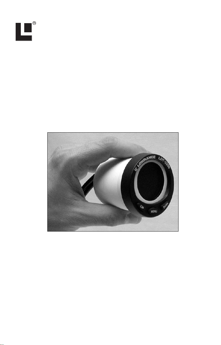
The LDT-3200 combines a temperature gauge, voltmeter and clock in one
housing. It displays the temperature in either Fahrenheit °F or Celsius
°C and may be set to rotate between four gauge displays or "pages." The
unit fits in a standard 2-1/8" (54 mm) hole used by most marine equipment manufacturers.
The gauge and its temperature sensor are designed to show surface water
temperature in a transom installation, but the sensor can be installed to
monitor the temperature elsewhere, such as in a live well.
LDT-3200 temperature gauge.
Mounting Preparations
When installed, the gauge will cover an area on the dash 2-3/8" (60.3 mm)
in diameter. To mount the unit, first make sure there is at least 2-3/4"
(70 mm) from the front of the dash to any obstruction behind the dash.
The maximum usable dash thickness is 1-1/8" (28.5 mm). Also, be sure
there is room to route the power and sensor cables. The following figure
shows gauge dimensions.
1
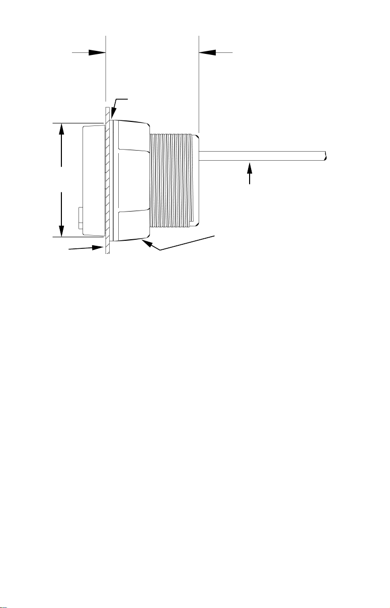
2-3/4"
(70 mm)
Gasket
2-3/8"
(60.3 mm)
Dash
Dash installation, cross-section view.
Cables
Threaded mounting collar
Caution:
You should read over the entire installation section before drilling
any holes in your vessel!
You can install this gauge in some other order if you prefer, but we recommend this installation sequence, which is summarized below:
1. Determine the location for the gauge so you can plan how and where to
route the cables. This will help you make sure you have enough cable
length for the desired configuration.
2. Determine the location of your battery or other power connections,
along with the power cable route.
3. Determine the location for the temperature sensor and its cable route.
4. Determine the location for the alarm buzzer and its wire route.
5. If you want to turn on the gauge backlights whenever you turn on your
dashboard lights, locate your boat's dash light switch and determine how
to route the dash light wires to it.
6. Install the temp sensor, connect power wires to the battery and route
the power/sensor cable to the gauge location.
7. Install the gauge, and connect the power/sensor cable.
8. Connect the buzzer wires and install the buzzer. If desired, connect the
dash light wires to the boat's dash light switch.
2
Recommended Tools and Supplies
Supplies are not included, unless otherwise indicated. A transom mount
requires one #8 stainless steel screw (3/4" long) and a high quality, marine-grade above- or below-waterline sealant/adhesive compound. If you
want to make a pilot hole for the screw, use a drill and a 1/8" drill bit. If
you prefer the option of routing the temp sensor cable through the transom (instead of over it), you will also need a 1/2" drill bit.
If the dash does not have a standard 2-1/8" (54 mm) hole, you will need a
drill or saw to make the hole. Carefully measure the dash thickness and
the hole area before cutting or drilling.
A screwdriver is needed for mounting the temp sensor. The buzzer installation requires two cable ties.
If you need to extend any of the wires, use a minimum of 24 gauge wire
and wire connectors of your choice. Wire nuts or electrical tape are required to cap any unused bare wires.
Mounting
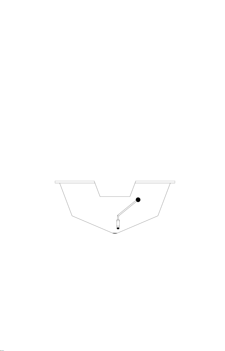
The temperature sensor can be mounted in any convenient location.
However, make sure it is placed on the transom where it will be in contact with the water at all times. Make sure the location does not interfere
with the boat's trailer.
Temp sensor on transom, with cable routed through the transom.
After determining the location, use the sensor as a template and mark
the hull for the screw's pilot hole, if desired. Route the sensor and cable
over or through the transom to the mounting location. If routing through
the transom, drill a 1/2" hole to accommodate the sensor. Attach the sensor to the hull with one #8 stainless steel screw, then seal the screw with
the below-waterline sealant compound.
Caution:
If you drill a hole in the transom for the cable, make sure it is located above the waterline. After installation, be sure to seal the cable hole with the same marine grade above-or below-waterline
sealant used for the screw.
3
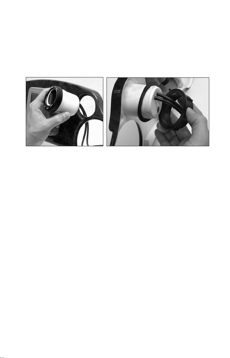
When you determine the location for the LDT-3200, drill a 2-1/8" (54 mm)
hole in the dash or use an existing gauge hole. Slide the unit's cables
through the hole from the front side of the dash, then push the LDT-3200
housing through the hole until it is flush with the dash surface. Make
sure the gauge is aligned correctly. Next, slide the rubber gasket and
plastic mounting collar over the cables and onto the back side of the
gauge.
Insert gauge through the hole in the front side of the dash (left). Slide
the rubber gasket over the cables, followed by the plastic collar (right).
Slide the gasket forward so it is flush with the back of the dash, then
screw on the mounting collar, turning it until it is snug against the gasket and the back of the dash.
Find a buzzer location that is protected from the elements, but still lets
you hear it. We recommend that you connect the buzzer wires, then use
two cable ties and attach the buzzer to one or both of the cables at the
back of the gauge. (Some dashboards are too thin to screw into.)
Finish the installation by connecting the cables as described in the following wiring diagrams and photos.
Wiring
The LDT-3200 operates from 10 to 15 volts DC (12-volt system). It must
be wired to a 1-amp fuse. Failure to use a fuse with this product will void
the warranty and could result in damage to the unit or your boat.
4
 Loading...