

Lowrance GlobalMap 1600, LMS-160 Installation And Operation Instructions Manual

INSTALLATION AND
OPERATION INSTRUCTIONS
LMS-160
and
GlobalMap 1600
TM

Copyright © 1998 Lowr ance Electronics , Inc.
All rights reserved.
GlobalMap 1600™ and LMS-160 are trademarks of Lowrance Electronics, Inc.
Lowrance® is a registered trademark of Lowrance Electronics, Inc.
W ARNING!
USE THIS UNIT ONLY AS AN AID T O NA VIGA TION. A CAREFUL NAVIGATOR NEVER RELIES ON ONLY ONE METHOD TO OBTAIN POSITION INFORMATION.
Never use this product while operating a vehic le.
CAUTION
When showing navigation data to a position (w aypoint), this unit will show
the shortest, most direct path to the waypoint. It provides navigation data
to the wa ypoint regardless of obstructions. Therefore , the prudent navigator will not only take advantage of all a vailable na vigation tools when travelling to a waypoint, but will also visually check to make certain a clear,
safe path to the waypoint is alwa ys available.
The operating and storage temperature f or your unit is from -4 degrees to
+167 degrees F ahrenheit (-20 to +75 degrees Celsius). Extended storage
temperatures higher or lower than specified will cause the liquid crystal
display to fail. Neither this type of failure nor its consequences are covered by the warranty. F or more inf ormation, consult the factory customer
service department.
All features and specifications subject to change without notice.
Lowrance Electronics may find it necessar y to change or end our poli-
cies, regulations, and special off ers at any time. We reserve the right to do
so without notice.
All screens in this manual are simulated.

This device complies with P art 15 of the FCC Rules. Operation is subject
to the following two conditions: (1) this device may not cause harmful
interference, and (2) this device must accept any interference received,
including interference that ma y cause undesired operation.
Note:
This equipment has been tested and found to comply with the limits f or a
Class B digital device, pursuant to P art 15 of the FCC Rules. These limits
are designed to provide reasonable protection against harmful interference in a residential installation. This equipment generates , uses and can
radiate radio frequency energy and, if not installed and used in accordance with the instructions, may cause harmful interference to radio communications. Ho wev er, there is no guar antee that interference will not occur in a particular installation. If this equipment does cause harmful interference to radio or tele vision reception, which can be determined by turning the equipment off and on, the user is encouraged to try to correct the
interference by one or more of the following measures:
• Reorient or relocate the receiving antenna.
• Increase the separation between the equipment and receiver.
• Connect the equipment into an outlet on a circuit different from that to
which the receiver is connected.
• Consult the factory customer service department for help.

Editing a W a ypoint ............................40
Edit Position..................................40
Edit Name ..................................... 41
Edit Icon........................................41
Delete a W aypoint.............................41
Delete All W a ypoints.........................41
Move a W a ypoint ..............................41
Wa ypoint Options ............................. 42
WAYPOINT NAVIGATION ........................... 42
Navigate to a cursor location..................43
Navigate to a W a ypoint using the Map ...43
CANCEL NAVIGATION ...............................43
ROUTES .....................................................44
Create a Route.......................................44
Add From W aypoint List....................4 4
Add From Map ..................................45
Delete a W aypoint .................................. 45
Wa ypoint Statistics ................................. 45
Following a Route .................................. 46
Wa ypoint Information ........................ 47
Delete a Route ....................................... 47
SYSTEM SETUP.........................................48
Sound ....................................................48
Contrast ................................................. 48
Backlight ................................................ 48
Set Local Time ....................................... 48
Units of Measure .................................... 49
NMEA / DGPS ....................................... 49
Configure NMEA Output ........................50
DGPS.....................................................5 0
Serial Communication Setup..................51
Reset Groups .........................................51
Reset Options ........................................ 51
System Info ............................................ 52
GPS SETUP................................................52
Position F ormat ...................................... 52
DATUM ...................................................53
Map Fix .................................................. 53
PCF (Position Correction F actor)............ 54
POSITION PINNING .............................. 55
GPS ALARMS ............................................. 56
DGPS MESSAGES ..................................... 57
SUN/MOON CALCULA T OR ........................57
SIMULATOR ................................................ 58
INST ALLATION ................................................. 1
Mounting........................................................1
Po wer Connections........................................2
Cable Connections ........................................3
GlobalMap 1600.......................................3
LMS-160 .................................................. 4
Antenna ........................................................5
T ransducer.....................................................6
INTRODUCTION TO GPS............................... 10
OPERA TION ................................................... 12
Satellite Status Screen ................................ 13
Finding Y our Position ................................... 14
Auto Search ...........................................14
Manual Initialization................................1 4
Position Acquisition ................................15
Modes ...................................................... 15
Navigation Screens ................................ 16
Course Deviation Indicator (CDI) ...... 18
Map ...................................................... 18
Cursor............................................... 19
Map Setup ........................................ 20
Change Maps ................................... 20
Map Options...........................................21
Map Orientation ................................ 21
Range Rings/Grid Lines ...................22
Autozoom .........................................22
Map Details ............................................ 23
Earth Map On/Off .............................23
T e xt Labels ....................................... 23
Map Detail ........................................ 23
Gray Fill ............................................ 24
Map Boundaries ............................... 24
Map Symbols....................................24
Locations .......................................... 25
Contour Lines ................................... 25
Plot T rail Options .................................... 25
Clear T rail ......................................... 25
Flash T rail ......................................... 25
Show T rail ......................................... 25
Save Trail .......................................... 25
Update T rail....................................... 26
ICONS ...................................................26
MAP DOWNLOADING........................... 28
WINDOWS.............................................29
Reprogram Window Groups .............34
Reprogram Bo xes.............................35
RESET GROUPS .................................. 35
WAYPOINTS .......................................... 36
Wa ypoint Menu ................................. 36
Saving Your Present Position as a
Wa ypoint (Quick Sa ve Method) ........ 36
Saving The Cursor Position as a
Wa ypoint........................................... 36
Saving Your Present Position as a
Wa ypoint (Select Number Method) ... 37
Saving a New Position ...................... 37
Wa ypoint Aver aging .......................... 38
Project a W a ypoint............................38
Selecting a W a ypoint ........................39
From List.......................................40
By Name ....................................... 40
Table of Contents

SONAR OPERATION...................................... 59
Sonar Modes ...............................................59
Full Chart ............................................... 59
Split Chart ..............................................59
Digital/Chart ...........................................59
Automatic..................................................... 60
Sonar Options.............................................. 60
Sensitivity...............................................60
Grayline.................................................. 61
Adjust Surface Clarity (SCC).................. 61
ASP (Advanced Signal Processing).......62
Range - Automatic ................................. 62
Manual.............................................. 63
Chart Options .........................................63
Chart Speed ..................................... 63
Chart Stop ........................................63
Upper and Lower Limits ......................... 64
Zoom......................................................64
Fish ID ...................................................65
FISHTRACK™ ....................................... 65
Chart Display ......................................... 66
Zoom Bar..........................................66
Zone Bar...........................................67
Chart Cursor .......................................... 67
Digital Sonar .......................................... 67
Alarms....................................................6 8
Depth Alarms....................................68
Zone Alarm ....................................... 69
Fish Alarm ........................................ 69
Keel Offset ............................................. 69
Calibrate Speed ..................................... 70
SONAR TROUBLESHOOTING....................... 71
UPS Return Service ........................................ 74
Warranty ......................................................76
Datum List ......................................................77
Table of Contents

Notes:

1
Thank you for purchasing a Lowrance product! You won't find another
combination GPS and sonar unit with these features and power for the
money! Each of our products is designed and manuf actured to precision
tolerances for long life under extreme conditions. We hope that you'll enjoy this product for years.
This manual covers both the Lowrance LMS-160 and GlobalMap 1600.
Both have 12-channel GPS receiv ers , ho w e ver, the LMS-160 also has a
sonar built into the unit. The installation of these two products vary due to
this difference, otherwise the oper ation of the two units (except f or sonar)
is virtually identical.
No matter which unit you own, please read the installation section carefully, especially the transducer section. Many times future trouble can be
avoided b y carefully locating and wiring the equipment.
If you do have problems, please read the troubleshooting section in the
back of this manual. You may find the solution to your prob lem there. The
Lowrance customer service department also has representatives available to answer your questions on our toll-free telephone lines. See the
back page of this manual for more information.
We want your experience with our equipment to be a happy one. Good
luck, and good fishing.
INSTALLA TION
Mounting - All Units
Install the unit in any convenient location, provided there is clearance
behind it when it is tilted for the best viewing angle. Holes in the bracket
base allow wood scre w or through-bolt mounting. You ma y need to place
a piece of plywood on the back of thin fiberglass panels to secure the
mounting hardware. Make certain there is enough room behind the unit to
attach the power and transducer cab les .
The gimbal bracket will also accept the GBSA-1 swivel bracket adapter
that lets you rotate the unit a full 360°.
The smallest hole that allows one power connector to pass through is 3/
4". After the hole is drilled, push other connectors up through the hole
first, then drop the power cable do wn through it.
2
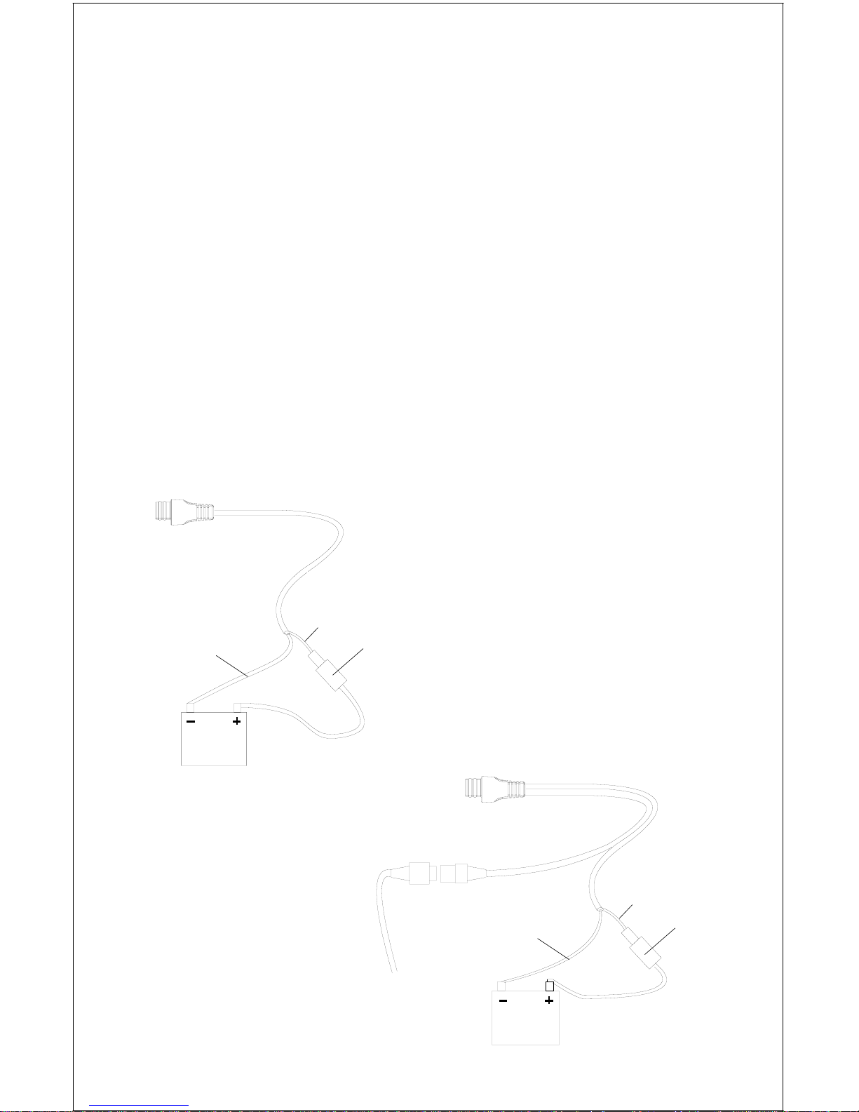
Po wer Connections - All Units
This unit works from a twelve-volt battery system. For the best results,
attach the power cable directly to the batter y. You can attach the power
cable to an accessory or power buss, however you may have problems
with electrical interference. Therefore, it’s safer to go ahead and attach
the power cable directly to the battery. If the cable is not long enough,
splice #18 gauge wire onto it. The power cable has two wires, red and
black. Red is the positive lead, b lac k is negativ e or g round. Make certain
to attach the in-line fuse holder to the red lead as close to the power
source as possible. F or example , if you hav e to extend the pow er cable to
the battery or power buss, attach one end of the fuse holder directly to the
battery or power buss. This will protect both the unit and the power cab le
in the ev ent of a short. Use a 3-amp fuse .
IMPORTANT!
Do not use this product without a 3-amp fuse wired into the power cable!
F ailure to use a 3-amp fuse will v oid y our warr anty.
3-AMP
FUSE
12-VOLT
BATTERY
3-AMP
FUSE
12-VOLT
BATTERY
TO
TRANSDUCER
RED
BLACK
RED
BLACK
LMS-160
POWER CONNCECTIONS
GLOBALMAP-1600
POWER CONNCECTIONS
3
If possible, route the unit’s power cable and transducer cable away from
other wiring. VHF radio antenna cables radiate noise when transmitting,
so be certain to keep the sonar’s wires away from it. You may need to
route the sonar unit’ s pow er cab le directly to the battery to isolate it from
other wiring on the boat.
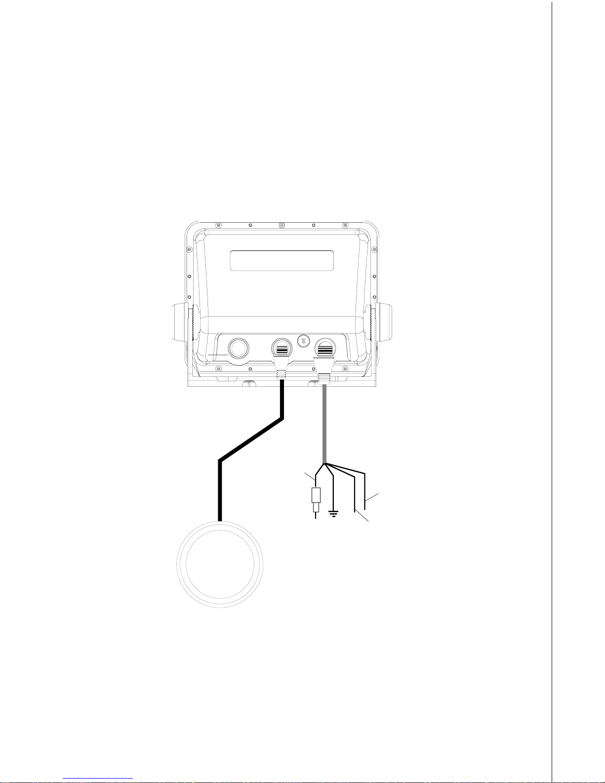
CABLE CONNECTIONS - GlobalMap 1600 Only
RED
(+12
VDC)
BLACK
(GROUND)
GREEN
(NMEA
RECEIVE)
ANTENNA
WHITE
(NMEA
TRANSMIT)
LOWRANCE
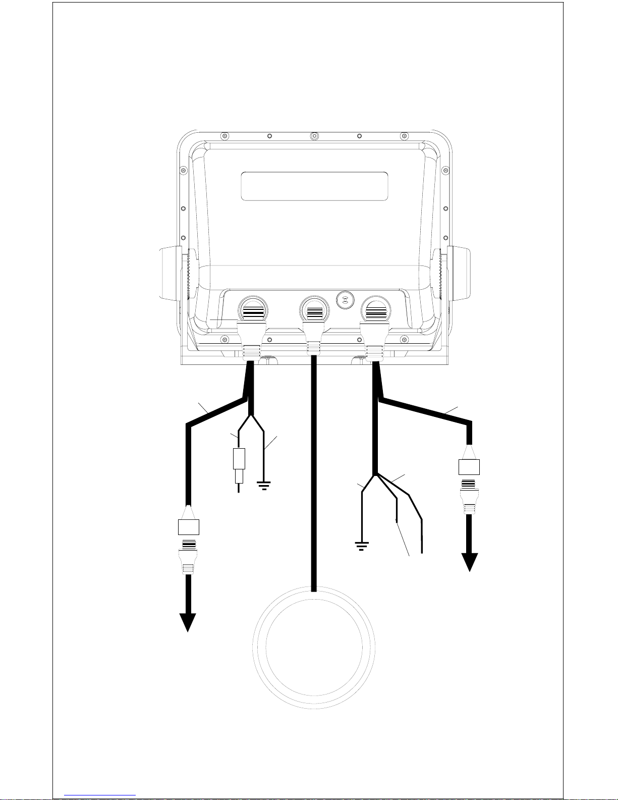
4
CABLE CONNECTIONS - LMS-160 Only
RED
BLACK
GREEN
(NMEA
RECEIVE)
ANTENNA
TO
TRANSDUCER
TO
SPEED/TEMP
SENSOR
(OPTIONAL)
WHITE
(NMEA
TRANSMIT)
LOWRANCE
BLACK
(GROUND)
TO
+12 VDC
See Note 1
Notes
1. If the NMEA wires are not used, then the NMEA adapter cable is not required. The
speed/temperature sensor's cable can be attached directly to the LMS-160.
NMEA
ADAPTER
CABLE
POWER/
TRANSDUCER
CABLE
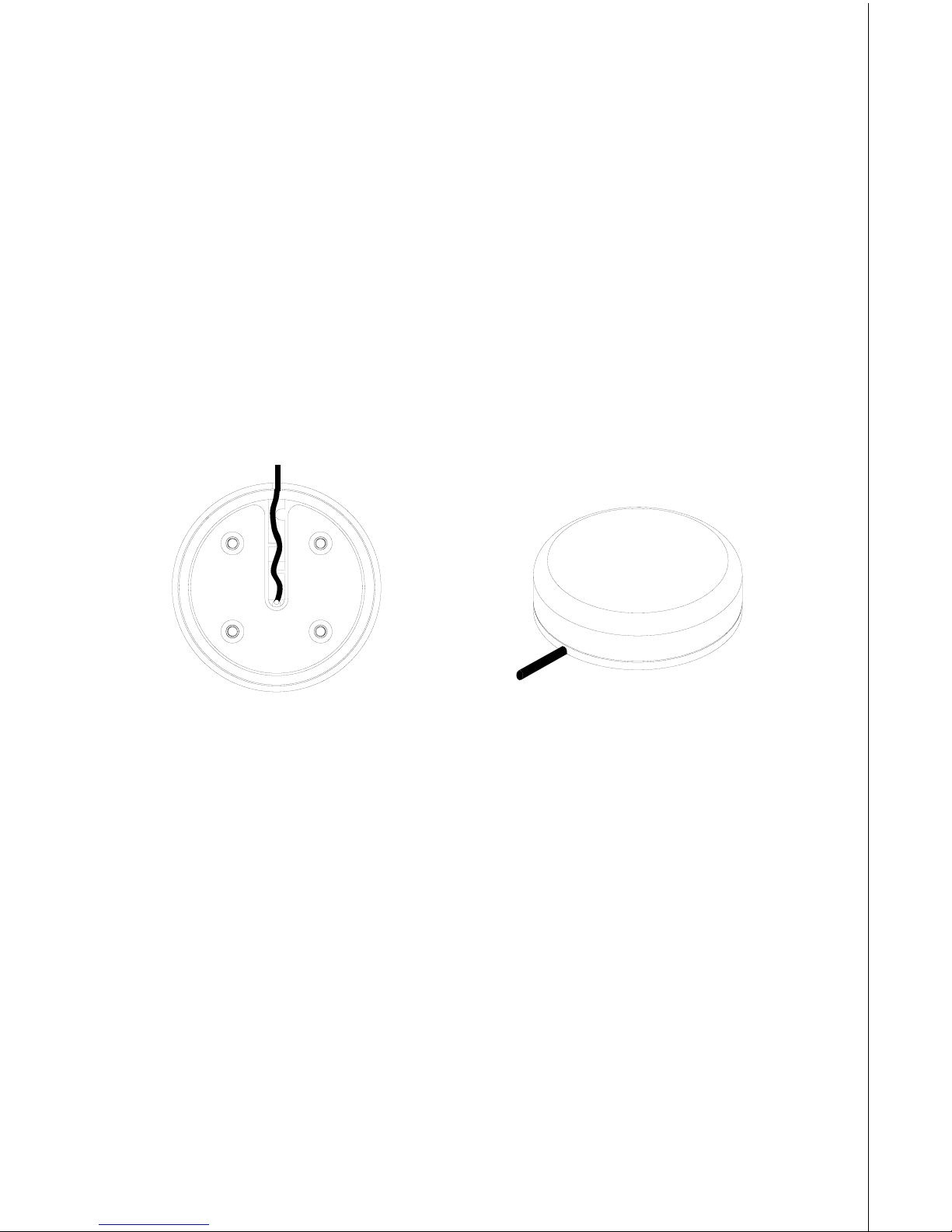
5
GPS Antenna Installation - All Units
The antenna can be mounted on any flat surf ace, pro vided y ou ha v e access behind the surface for the mounting screws. A magnet is also supplied that can be epoxied to the bottom of the antenna. A pole mount
adapter lets you mount the antenna on a pole or swivel mount that uses
standard 1" - 14 threads. The antenna has 25 feet of cab le . Do not cut or
splice this cable.
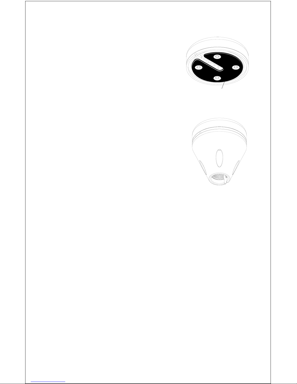
Surface Mount
The antenna can be easily installed on any flat surface that is at least 90
mm (3 1/2") wide. Mak e certain that a clear view of the sky is availab le at
the selected location. Since the GPS signals travel “line-of-sight”, nearly
anything bloc king the antenna can potentially obstruct the unit from finding a satellite. Do not mount it in front of radar antennas. They radiate high
energy that can interfere with the GPS signal.
Once you’v e determined the mounting location, use the template on page
51 in this manual to drill the holes for the screws. The screws, supplied
with this antenna, are 4mm x 30mm. (about 1 1/8" long). Drill 4.75 mm (3/
16") holes for the mounting screws. If you route the cable through the
mounting surface, y ou’ll need to drill a 25 mm (1") hole f or the cab le .
There is a notch in the antenna housing that allows the cable to pass
through to the outside, instead of routing it through the mounting surface .
After drilling the holes, pass the o-ring over the antenna cable and press
it into the groove on the bottom of the antenna housing. Now attach the
antenna to the mounting surface, using 4mm screws and the supplied
lock washers. Route the cable to the GPS receiver and the antenna installation is finished.
6
Magnet Mount
A magnet lets you temporarily mount the antenna on any ferrous metal surf ace. (such as a
car) To use the magnet, simply epoxy it to the
bottom of the antenna, using the epoxy supplied with your antenna. Carefully f ollow the instructions on the epoxy package and apply it
to the magnet. Then carefully press the magnet to the bottom of the antenna housing. After
the epoxy cures (in about 30 minutes), the antenna is ready for use.
Pole Mount
The antenna attaches to the pole mount adapter
with the supplied 4 mm screws. You can route
the antenna cable through the slot in the side of
the antenna, or pass it down through the pole
mount adapter. A slot next to the threads in the
pole mount adapter places the cable ne xt to the
pole where it can be easily routed down the pole
to the GPS receiver. The threads on the pole
mount adapter accept a standard marine antenna
mount.
MAGNET
SPEED/TEMPERATURE SENSOR - LMS-160 ONLY
If you’re installing a temperature or speed/temperature sensor, read the
sensor’s mounting instructions before making the installation. Route the
sensor’s cable directly to the LMS-160 and plug it into the connector on
the NMEA/DGPS cable. The speed/temp sensor plugs into the optional
SAM sonar module on the GlobalMap 1600.
TRANSDUCER INSTALLATION - LMS-160 ONLY
(Note: A transducer is not included with all units. You may need to purchase the transducer separately.)
The HS-WSBK supplied with this unit is a transom mount transducer. It
can be installed on any outboard or stern-drive (inboard\outboard) powered boat. It can also be permanently installed inside the boat to “shootthrough” the hull on some fiberglass boats .
The “kick-up” mounting bracket helps prevent damage if the transducer
strikes an object while the boat is moving. If the transducer does “kickup”, the brack et can easily be pushed bac k in place without tools .
POLE MOUNT
7
Read this section carefully before attempting the installation. Determine
which of the mounting positions is right for your boat. Remember, the
transducer location is the most critical part of a sonar installation.
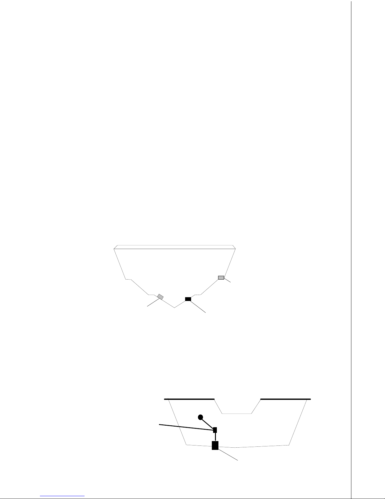
Location - General
1. The transducer must be placed in a location that has a smooth flow of
water at all times. If the transducer is not placed in a smooth flow of
water, interference will show on the sonar’s display in the form of random lines or dots whenev er the boat is moving.
2. The transducer should be installed with it’s f ace pointing straight down,
if possible.
3. Make certain the transducer’s location doesn’t interfere with the trailer
or hauling of the boat. Also, don’t mount it closer than approximately
one foot from the engine’ s lo wer unit. This will pre vent ca vitation interference with the propeller . Typically , the transducer should be mounted
as deep in the water as possible . This increases the chance that it will
be in the water in high speed and reduces the possiblity of air bubble
interference.
POOR ANGLEPOOR ANGLE
POOR ANGLEPOOR ANGLE
POOR ANGLE
GOOD LOCATIONGOOD LOCATION
GOOD LOCATIONGOOD LOCATION
GOOD LOCATION
POOR LOCATIONPOOR LOCATION
POOR LOCATIONPOOR LOCATION
POOR LOCATION
4. If possible, route the transducer cable away from other wiring on the
boat. Electrical interference from VHF r adio, engine wiring, bilge pumps,
and areators can be display ed on the sonar’s screen. Use caution when
routing the transducer cable around these wires.
CAUTION!CAUTION!
CAUTION!CAUTION!
CAUTION!
CLAMP THE TRANSDUCER CABLE TOCLAMP THE TRANSDUCER CABLE TO
CLAMP THE TRANSDUCER CABLE TOCLAMP THE TRANSDUCER CABLE TO
CLAMP THE TRANSDUCER CABLE TO
TRANSOM NEAR THE TRANSDUCER. THISTRANSOM NEAR THE TRANSDUCER. THIS
TRANSOM NEAR THE TRANSDUCER. THISTRANSOM NEAR THE TRANSDUCER. THIS
TRANSOM NEAR THE TRANSDUCER. THIS
WILL HELP PREVENT THE TRANSDUCERWILL HELP PREVENT THE TRANSDUCER
WILL HELP PREVENT THE TRANSDUCERWILL HELP PREVENT THE TRANSDUCER
WILL HELP PREVENT THE TRANSDUCER
FROM ENTERING THE BOAT IF IT ISFROM ENTERING THE BOAT IF IT IS
FROM ENTERING THE BOAT IF IT ISFROM ENTERING THE BOAT IF IT IS
FROM ENTERING THE BOAT IF IT IS
KNOCKED OFF AT HIGH SPEED.KNOCKED OFF AT HIGH SPEED.
KNOCKED OFF AT HIGH SPEED.KNOCKED OFF AT HIGH SPEED.
KNOCKED OFF AT HIGH SPEED.
GOOD LOCATIONGOOD LOCATION
GOOD LOCATIONGOOD LOCATION
GOOD LOCATION
8
Transducer Assembly and Mounting
The best way to install this transducer is to loosely assemble all of the
parts first, then place the transducer’s bracket against the transom and
see if you can mov e the tr ansducer so that it’s parallel with the ground.
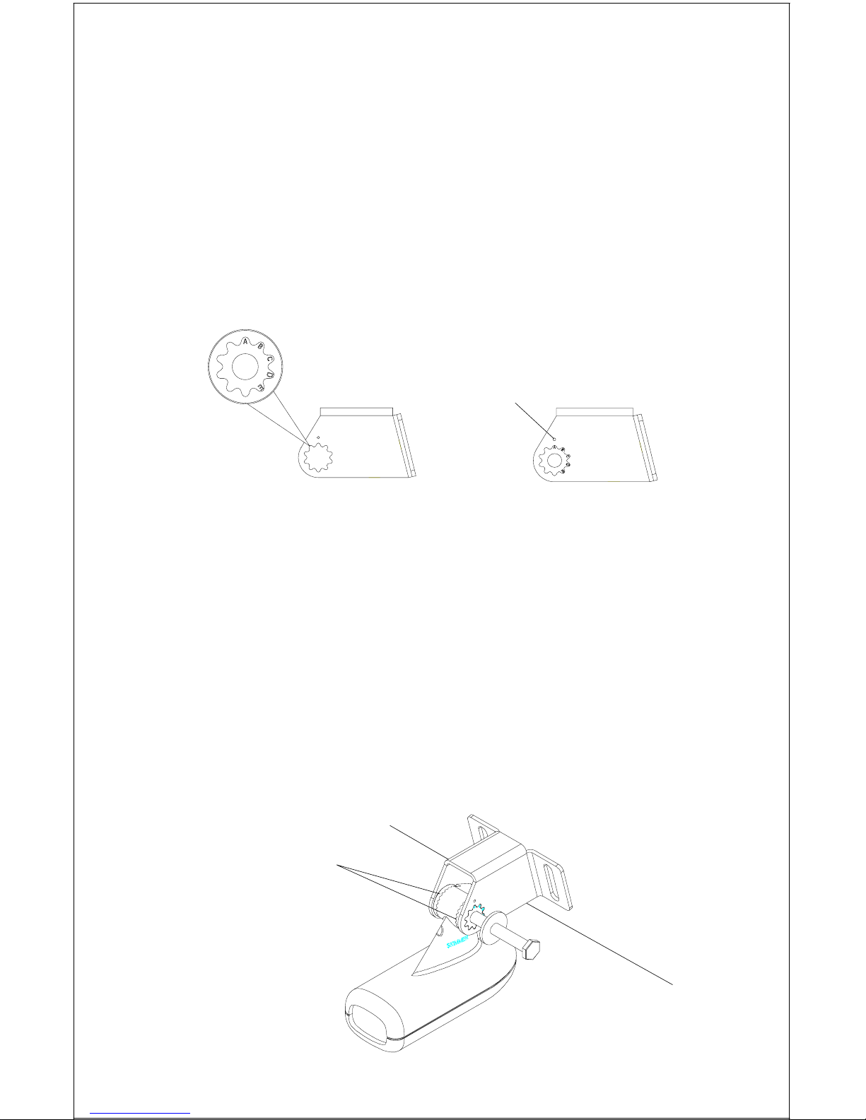
1. Press the two small plastic ratchets into the sides of the metal brack et
as shown below . Notice there are letters molded into each ratchet. Place
each ratchet into the bracket with the letter “A” aligned with the dot
stamped into the metal bracket. This position sets the transducer’s
coarse angle adjustment for a f ourteen (14) degree transom. Most outboard and stern-drive transoms have a f ourteen degree angle.
DOT
2. Slide the transducer between the two ratchets. T emporally slide the bolt
though the transducer assembly and hold it against the transom. Looking at the transducer from the side, chec k to see if it will adjust so that
its face is parallel to the ground. If it does, then the “A” position is correct for y our hull. If the transducer’s face isn’t parallel with the g round,
remove the tr ansducer and ratchets from the brac k et. Place the ratchets into the holes in the bracket with the letter “B” aligned with the dot
stamped in the bracket. Reassemble the transducer and bracket and
place them against the transom. Again, check to see if you can move
the transducer so it’ s parallel with the ground. If it does, then go to step
3. If it doesn’t, repeat step 2, but use a different letter until you can
place the transducer on the transom correctly.
RATCHETS
9
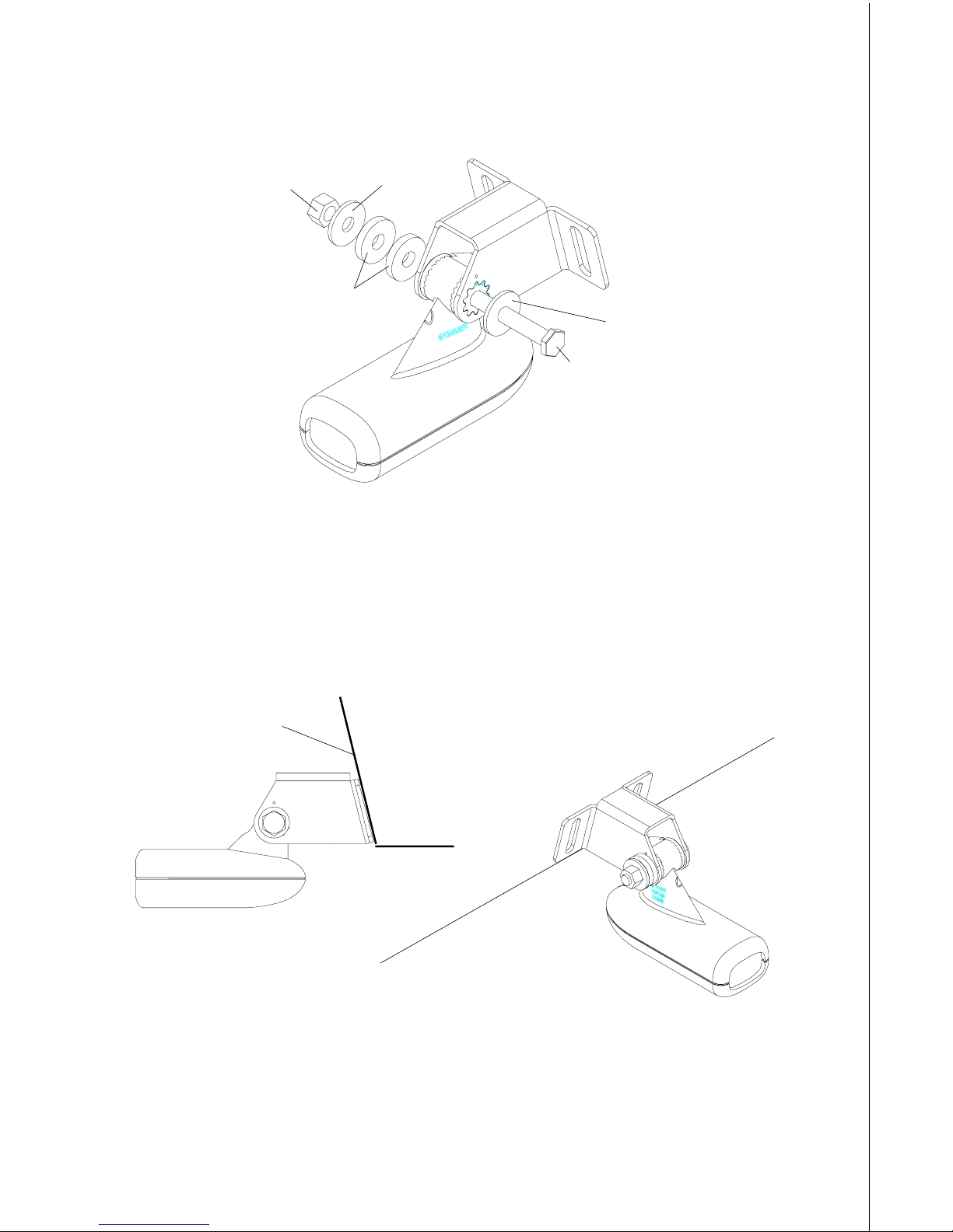
3. Once you determine the correct position for the ratchets, assemble the
transducer as shown below. Don’t tighten the lock nut at this time.
4. Hold the transducer and bracket assembly against the transom. The
transducer should be roughly parallel to the ground. The bottom of the
transducer brack et should be in line with the bottom of the hull. Don’t let
the bracket extend below the hull! Mark the center of the slots for the
mounting holes. Drill two 5/32" holes in the marked locations for the
#10 screws supplied with the transducer .
NUT
METAL
WASHER
RUBBER
W ASHERS
METAL
WASHER
BOLT
TRANSOM
SIDE VIEW
5. Attach the transducer to the transom. Slide the transducer up or do wn
until it’s aligned properly on the transom as shown above. Tighten the
brack et’ s mounting screws. Adjust the transducer so that it’ s parallel to
the ground and tighten the lock nut until it touches the flat w asher, then
add 1/4 turn. Don’t over tighten the lock nut! If you do, the transducer
won’t “kic k-up” if it strikes an object in the water.

10
6. Route the transducer cable to the sonar unit. If possible, route the transducer cable away from other wiring on the boat. Electrical noise from
the engine’ s wiring, bilge pumps, VHF radio wires and cables , and aerators can be picked up by the sonar . Use caution when routing the transducer cable around these wires.
IMPORTANT!
Clamp the transducer cable to the transom close to the transducer. This
can prevent the transducer from entering the boat if it is knocked off at
high speed.
7. Make a test run to determine the results. If the bottom is lost at high
speed, or if noise appears on the display, try sliding the transducer
brack et down. This puts the tr ansducer deeper into the water, hopefully
below the turbulence causing the noise. Don’t allow the transducer
brack et to go below the bottom of the hull!
Periodically wash the transducer’s face with soap and water to remove
any oil film that ma y collect. Oil and dirt on the face will reduce the sensitivity or may e v en pre vent operation.
INTRODUCTION T O GPS
The Global P ositioning System (GPS) was developed b y the United States
Department of Defense as a 24-hour a day, 365 days a year global navigation system for the military . Civilian av ailability was added (but with less
accuracy) using the same satellites. Twenty-four satellites orbit the Earth.
Three of these satellites are spares, unused until needed. The rest virtually guarantee that at least four satellites are in vie w nearly anywhere on
Earth at all times.
The system requires three satellites in order to determine a position. This
is called a 2D fix. It takes four satellites to determine both position and
elev ation, (your height abo v e sea le v el - also called altitude.) called a 3D
fix.
Remember, the unit must have a clear view of the satellites in order to
receive their signals. Unlike radio or television, GPS works at very high
frequencies. The signals can be blocked easily by trees, buildings, even
your body.
Nev er use this GPS receiv er while oper ating a v ehicle!
Like most GPS receivers, this unit doesn’t have a compass or any other
navigation aid built inside . It relies solely on the signals from the satellites

11
to calculate a position. Speed, direction of travel, and distance are all
calculated from position information. Therefore, in order f or it to determine
direction of travel, you must be moving and the faster, the better. This is
not to say that it won’t work at trolling speeds - it will. There will simply be
more “wandering” of the data shown on the display.
Another factor that greatly influences the receiver’s ability to determine
position is SA. The United States government intentionally degrades the
satellite’s signal for civilian users. They introduce small errors into the
signals that makes the GPS receiv er less accurate. These errors are called
selective availability, or SA. How bad is it? The y guar antee that the position reported by a GPS receiver that meets their specifications is within
100 meters horizontally and 150 meters vertically 95% of the time. (The
position can be worse than that the other 5% of the time.) In other words,
the position shown on your receiver is within 100 meters of your actual
position, 95% of the time. That’ s o ver 300 f eet! Not exactly pinpoint accuracy, but then few people need positioning accuracy greater than this.
However, if you do want better performance, (and who doesn’t?) many
manufacturers (including Lowrance) sell a DGPS receiver that attaches
to your GPS receiver . The DGPS system transmits correction signals that
nullify the effects of SA. The DGPS receiver takes signals from these
land-based transmitters and gives them to the GPS receiver which then
uses them to show a more accurate position. The ironic part is the federal
government implemented SA and is also operating man y DGPS transmitters. (You can use the signals from all of the Coast Guard DGPS stations
for free, by the way.) The downside to this is it requires another piece of
electronic gear (the DGPS receiver). And you ha ve to be close enough to
a station to receive the DGPS signals.
Generally, you find that using your GPS receiver without DGPS is both
easy and amazingly accurate. It’s easily the most accurate method of
electronic navigation available to the general public today. Remember,
howe v e r, that this receiver is only a tool. Alw a ys ha v e another method of
navigation a v ailable, such as a chart or map and a compass.
Also remember that this unit will always show navigation information in
the shortest line from your present position to a waypoint, regardless of
terrain! It only calculates position, it can’t know what’s between you and
your camp , for example . It’s up to y ou to safely navigate around obstacles ,
no matter how you’re using this product.
12
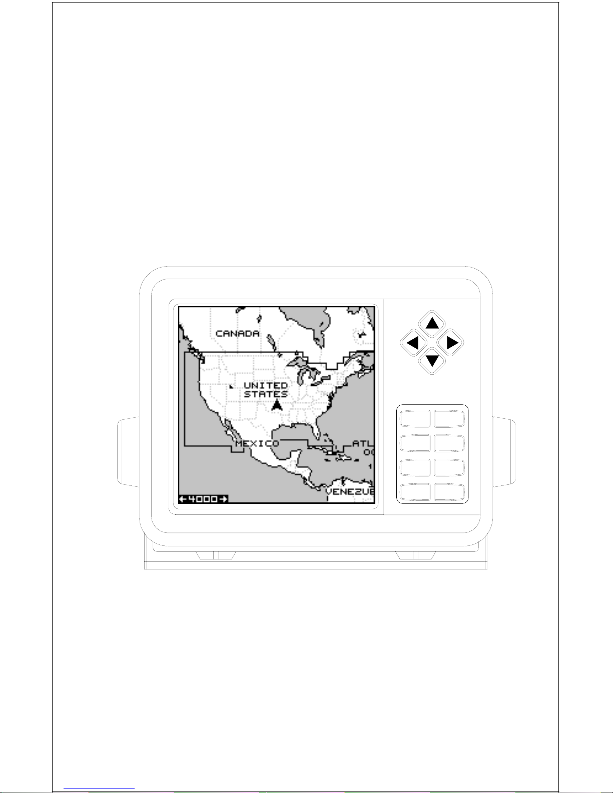
GPS OPERATION
There are 12 ke ys on the keyboard. You can navigate through the men us,
adjust the chart’s cursor, and enter data using the arrow keys. The five
major modes of operation are accessed using the PAGES ke y. Press the
MENU key to select or adjust a feature from a list. The Z-IN and Z-OUT
keys zoom-in or zoom-out the view on the plotter screen. The ENT and
EXIT keys are used to enter or clear data or screens. Save and edit
waypoints using the WPT key. The PWR key tur ns the unit on and off.
Pressing it once while the unit is operating turns on the screen’s backlight. To prevent an accidental shutdown, you must hold the PWR key
down for a f ew seconds to turn the unit off.
PWRENT
MENU EXIT
PAGES WPT
ZOUT
ZIN
LOWRANCE
Most of the unit’ s features are f ound on “menus’. You can view the menus
by pressing the MENU key. This product has “Intelligent Menus”. There
are many menus that pertain to only the sonar, for example. When you
press the MENU ke y and the sonar is showing, menu items f or the sonar
show in addition to the normal menus. F or e xample, if the sonar is sho wing, and you press the MENU ke y , GPS map items won’t sho w on the list.
This helps you find the needed item without scrolling through unnecessary menus.
13
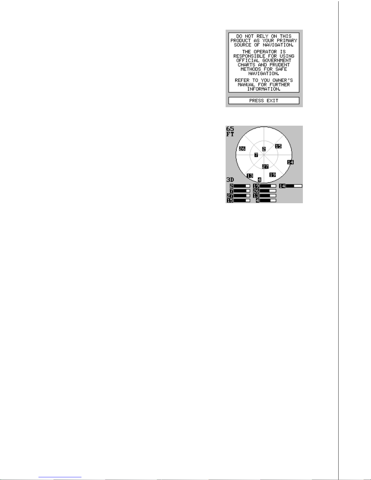
To turn the unit on, simply press the PWR key . A
GPS logo screen appears, then the screen similar to the one at right appears. Read the message on the screen, then press the EXIT key to
erase it or wait a few seconds and it automatically clears. The screen shown below appears
next.
This screen appears each time you turn the unit
on. It shows a graphical vie w of the satellites that
are in view. Each satellite is sho wn on the circular chart relative to your position. The point in the
center of the chart is directly overhead. The small
inner ring represents 45° above the horizon and
the large ring represents the horizon. North is at
the top of the screen. You can use this to see
which satellites are obstructed by obstacles in
your immediate area if you hold the unit facing
north.
The GPS receiver is tracking satellites that are surrounded by a black
box. The receiver hasn't locked onto a satellite if it's number isn't surrounded by a box, therefore it isn’t being used to solve the position.
Beneath the circular graph are the bar graphs, one for each satellite in
view . Since the unit has tw elve channels, it can dedicate one channel per
visible satellite. Therefore, if only six satellites are visible, only six bar
charts show at the bottom of the screen. The wider the bar on the g raph,
the better the unit is receiving the signals from the satellite.
The number in the upper left corner is the “expected horizontal position
error” or e xpected error from a benchmark location. In other w ords , if the
expected error sho ws 50 feet, then the position sho wn by the unit is estimated to be within 50 feet of the actual location. Howe v er , this n umber is
only valid if you’re using DGPS or if S/A is turned off. Due to S/A, the
accuracy can only be less than 100 meters, 95% of the time, per U.S.
gover nment specifications. Although the expected error is not accurate
unless you hav e a DGPS receiv er, it does give y ou an indicator of the fix
quality the unit currently has. The smaller the e xpected error number , the
better (and more accurate) the fix is. If the expected error flashes, then
the unit hasn't locked onto the satellites , and the number shown isn't valid.
A light bulb indicator at the top right corner of the screen appears when
the backlights are on.
14
FINDING Y OUR POSITION
Auto Sear ch
To lock onto the satellites, the GPS receiver needs to know it’s current
position, UTC time, and date. (Ele vation (altitude) is also used in the equation, but it’ s rarely required to determine a position.) It needs this data so
that it can calculate which satellites should be in view . It then searches for
only those satellites. When your GPS receiver is turned on for the first
time, it doesn’t know what your position or elevation (altitude) is. It does
know the current UTC time and date since these were progr ammed into it
at the factory and an internal clock keeps the time while the unit is turned
off. It begins searching for the satellites using the above data that it acquired the last time it was turned on. This probably was at the factory.
Since it’s almost certain that you’ re not at our factory , it’ s probably looking
for the wrong satellites. If it doesn’t find the satellites it’s looking for after
five minutes, it switches to Auto Search. The receiver looks f or any satellite in the sky. Due to advanced technology, the auto search time has
shrunk to about five minutes, so the longest time y ou should ev er hav e to
wait is ten minutes from the time you turn the unit on until it locks onto the
satellites and shows a position. Once the unit locks onto the satellites, it
should take less than a minute to find y our position the next time it’s turned
on, provided you ha ven’t mov ed more than approximately 100 miles from
the last location it was used.
Manual Initialization
If you don’t want to wait for the Auto Search, then you may be able to
speed up the initialization process by using the manual initialization feature. Using this feature tells the unit it’ s approximate position. Once it knows
it’s location, it determines exactly which satellites should be in view and
starts looking only for those satellites.
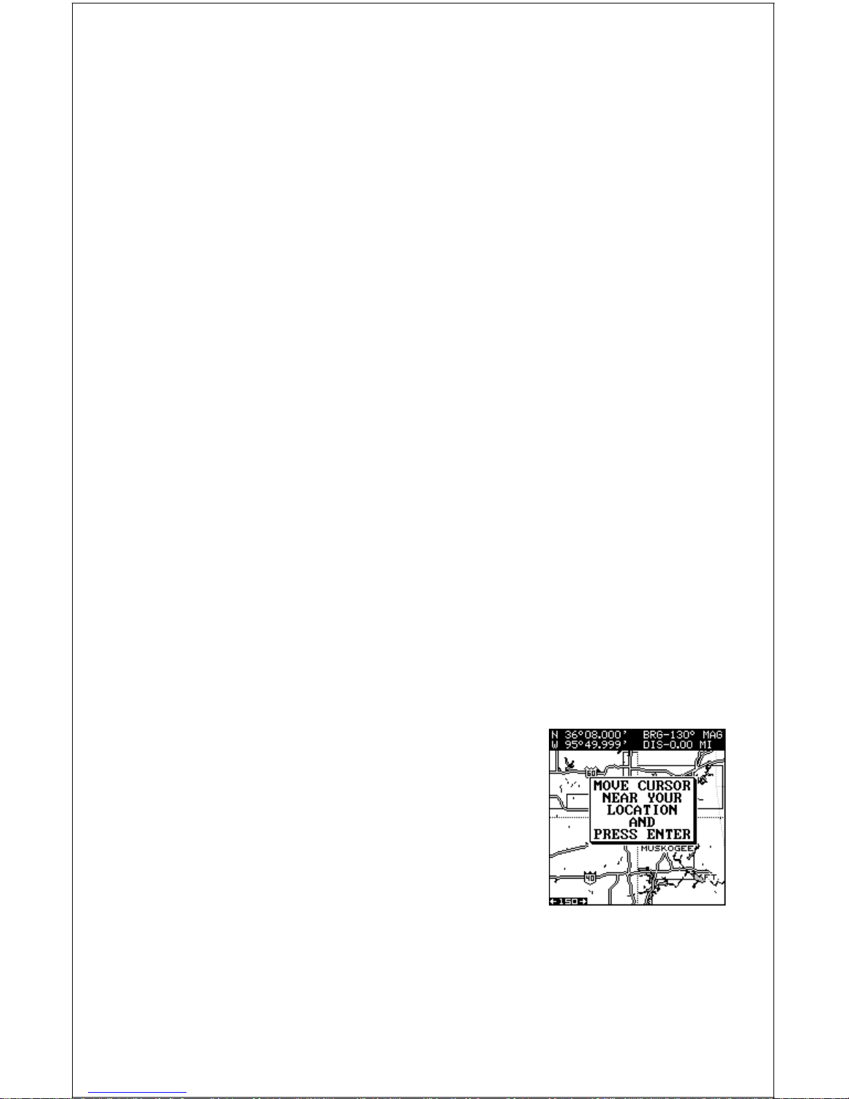
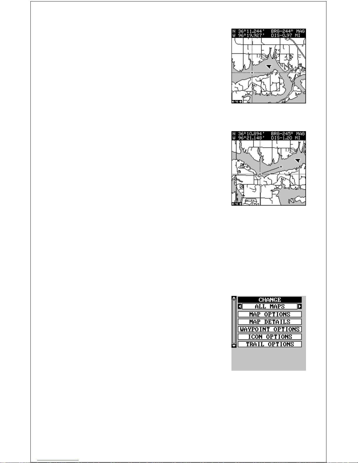
To manually initialize the unit, press the MENU
ke y . No w press the down arrow key until the “GPS
SETUP” label is highlighted. Press the r ight arrow key. The “INITIALIZE GPS” label is highlighted. Press the right arrow key again. A screen
similar to the one at right appears. Use the arrow
keys to mo ve the crosshairs to your appro ximate
location on the map. You can use the ZIN and
ZOUT keys to enlarge the map which makes it
easier and faster to find your location. The box at the top of the screen
shows the latitude and longitude of the cursor position, along with the
distance and bearing from the last known position. Once you have the
crosshairs on your location, press the ENT key. The unit returns to the
satellite status screen.

15
Using the manual initialization method loads a position that’s close to
yours into the GPS receiver. It should no w have position, time, and date,
thereby giving it the data it needs to determine which satellites are in
view. Once the satellites are known, the receiv er searches f or only those
satellites, making a lock f aster than an auto search method.
All position and navigation data flashes until the unit acquires a position.
Do not rely on any data that is flashing! When the n umbers are flashing,
they represent the last known values when the unit lost it’s lock on the
satellites.
Position Aquisition
When the receiver locks onto the satellites and calculates a position, it
shows the message “P osition Acquired” on the screen. Once the unit has
acquired the satellites and the position acquired message appears, it’s
ready for use.
(Note: The altitude data may still flash even if the unit shows a “Position
Acquired” message and all other data is not flashing. The unit must be
locked onto at least f our satellites to determine altitude. It only takes three
satellites to determine position. You can navigate with this unit if the altitude is flashing, simply ignore the altitude display until it quits flashing.)
REMEMBER, DO NOT NAVIGATE WITH THIS UNIT UNTIL THE NUMBERS STOP FLASHING!
MODES
The LMS-160 has five modes: status, navigation, sonar, map, and window groups. The GlobalMap 1600 has four - no sonar mode. Use the
PAGES and arrow ke ys to s witch between the diff erent screens. The f our
GPS screens that show by def ault are shown at the top of the ne xt page .
(See the sonar section in this manual for inf ormation on sonar operation.)
To change modes, simply press the PAGES k ey.
A screen similar to the one at right appears. Use
the up or down arrow k eys to change modes. (The
windows mode is shown as “groups”. Group “A”
is the first windows group.)
Press the right arrow ke y while the above menu
is showing to switch between different versions
of each mode. When the desired screen appears ,
press the EXIT key to er ase the menu.
16
STATUS NAVIGATION SONAR
(GLOBALMAP 1600
ONLY)
MAPPING WINDOW GROUPS
Navigation
There are two different na vigation screens. Nav screen number one shows
a graphical view of your trip, Nav screen number 2 shows all navigation
details in large digital numbers. You can also customize both navigation
screens to show data other than the def ault. See the “Programming Box es”
section for more inf ormation.
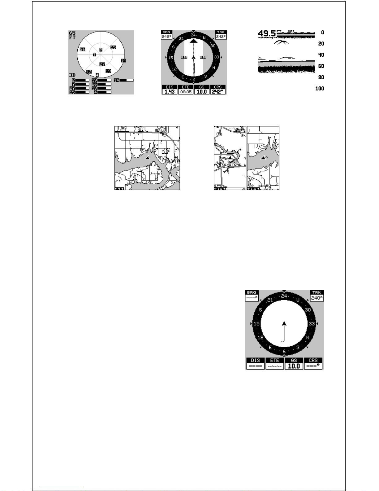
Nav-1
This screen has a compass rose that shows not
only your direction of travel, but also the direction to a recalled waypoint. The navigation screen
looks like the one at right when you’re not navigating to a waypoint. Your position is shown by
an arrow in the center of the screen. Your trail
history, or path you’ve taken is depicted by the
line extending from the arrow . The arrow pointing
down at the top of the compass rose indicates
the current track (direction of tra v el) you are taking. This is also shown in
the “TRK” (track) box in the upper right corner of the screen. On the example shown at right, the track is 240°. The current ground speed (GS)
shows in the box in the low er center of this screen.
When navigating to a waypoint, Nav screen number one looks like the
one at the top of the next page. Bearing to the destination wa ypoint is in
the box in the upper left corner . Bearing is also shown by the large arrow
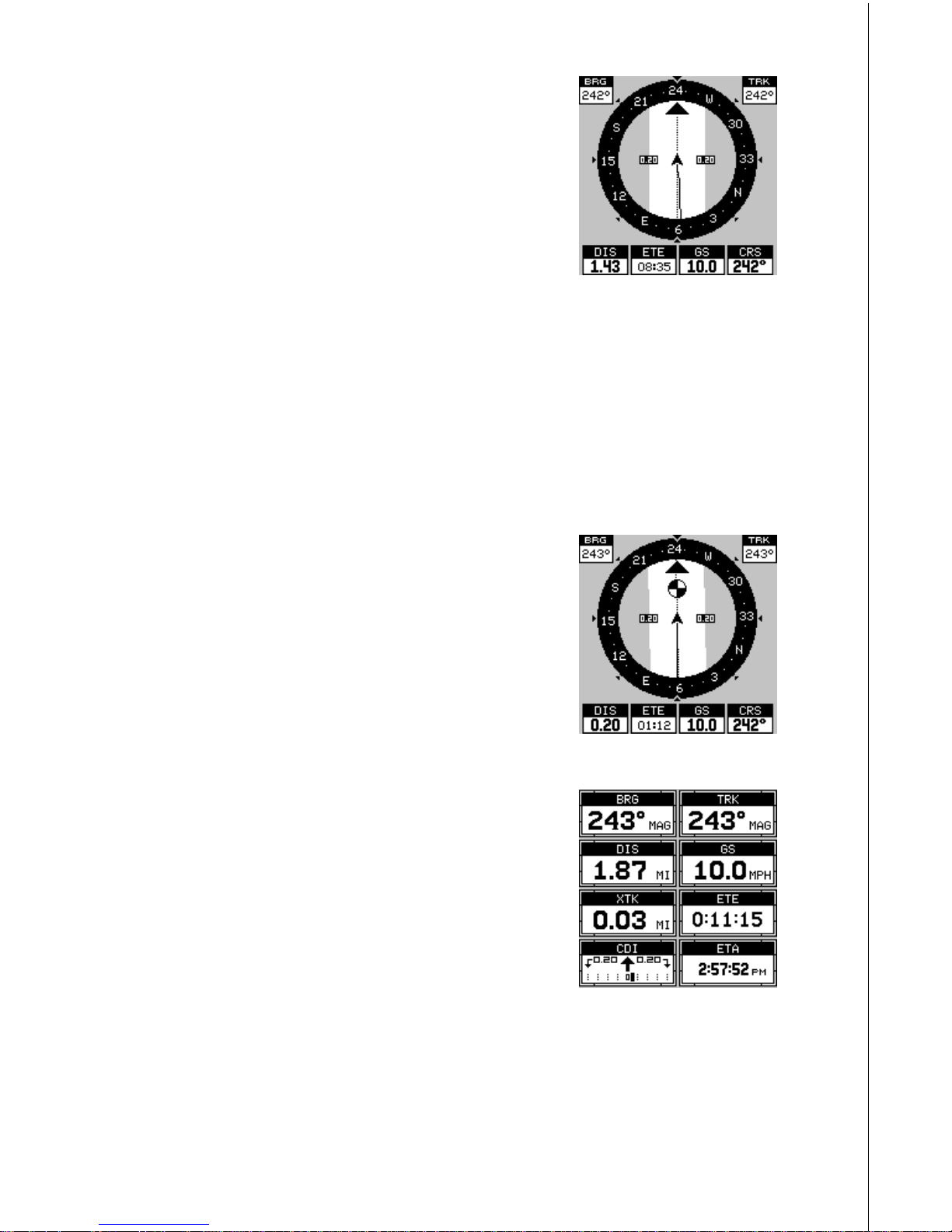
17
pointing up towards the compass, above the
present position arrow . Distance from the present
position to the waypoint (DIS) sho ws beneath the
compass on the lower left side of the screen. Next
to the distance box is estimated time enroute
(ETE). This is the estimated time that it will tak e
you to arrive at the destination, based upon current track and ground speed. In the lower right
corner is the course (CRS) box showing the direction from your starting position to the waypoint. Remember, a course
is a proposed path from the starting position to the destination. Track is
your actual direction of travel.
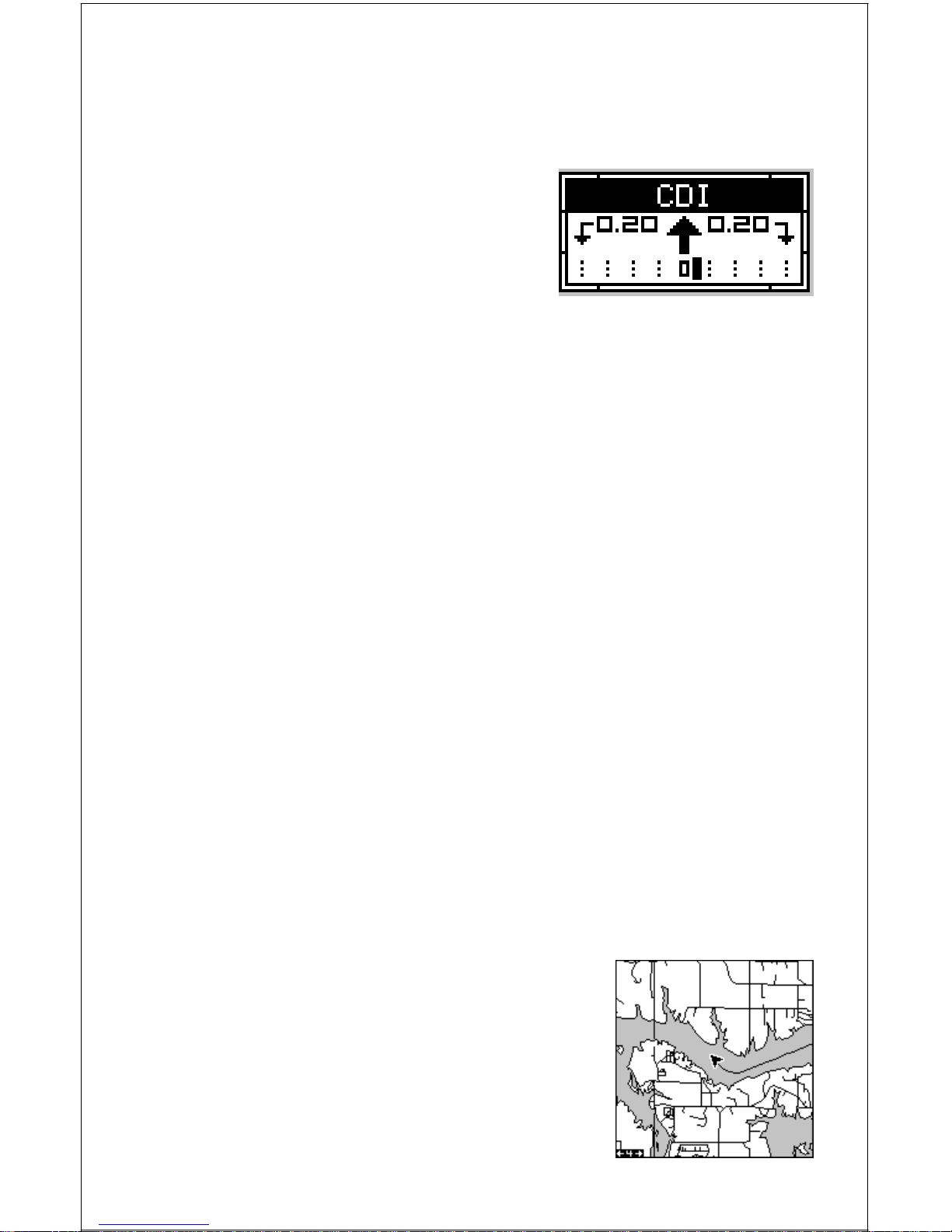
Lines on either side of the present position show the current cross track
error range. Cross track error is the distance you are off-course to the
side of the desired course line. The course line is an imaginary line drawn
from your position when you started navigating to the destination waypoint. It’ s shown on the screen as a vertical dotted line. The def ault for the
cross track error r ange is 0.20 mile. For example ,
if the present position symbol touches the right
cross track error line , then you are .25 mile to the
right of the desired course. You need to steer left
to return to the desired course. You can use the
ZIN or ZOUT ke ys to change the cross tr ac k error range. A circle depicting your destination (wa ypoint) appears on the screen as you approach
the waypoint as sho wn on the screen at right.
Nav-2
This navigation screen shows all navigation information in large digital numbers. To view this
screen, press the PAGES key, then press the up
arrow key until the “NAV 1” label is highlighted.
While it’s highlighted, press the right arrow key.
The screen shown at right appears. Press the
EXIT key to er ase the menu.
This screen is composed of eight digital boxes.
Track (TRK) and ground speed (GS) data are the only ones that show
data if you’ re not na vigating to a wa ypoint. If you are na vigating to a wa ypoint, then bearing (BRG), distance to waypoint (DIS), estimated time en
route (ETE), cross track error (XTK), estimated time of arriv al (ETA), and
the CDI also operate.
18
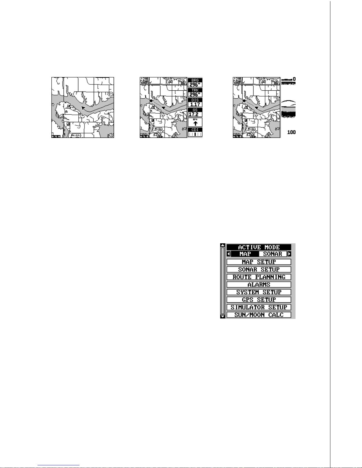
Course Deviation Indicator (CDI)
Once navigation to a waypoint is established, the CDI shows your distance to the left or right of the desired course. The vertical line in the box
shows both the direction you must steer to
get back on course and the distance to the
course line. For example, if you’re travelling straight towards the destination, from
the start, then the line stays in the center.
If you drift off course to the right, the line
moves to the left. This signifies that you
need to steer to the left to get back on course. This is called “chasing the
needle”. If you steer tow ards the line (needle), you’ll always be heading in
the correct direction to get back on course.
The CDI’ s range shows beneath the CDI label. On the abov e screen, the
CDI range is .20 mile, which is the default. You can adjust the range by
selecting “ALARMS” on the main menu, then “GPS ALARMS”. Highlight
the “CDI DIS” label, then use the left or right arrow key to adjust it. The
CDI range is also shown by the dotted lines at the f ar left and right side of
the CDI indicator . If the solid line is on either of the dotted lines , then yo u
are 0.20 mile off course. Remember , if the line moves to the left, then y ou
are too far to the right of the desired course line and vice-versa.
Using the CDI with a mapping screen helps you visualize y our position in
relation to the course. The screen on the right shows that we are off course
to the right. The v ertical bar has moved to the left side of the CDI, showing
the direction to the desired course line. The CDI gives you a quick, easy to
read visual indicator of your relationship between your direction of travel
and the desired direction.
Map
This unit has a ground map of the world built inside. This map has the
majority of its detail in far southern Canada, the continental United States
and Hawaiian islands , northern Mexico, the Bahamas, and Bermuda. The
map screens show your course and track from a “birds-eye” view . If you’ re
navigating to a waypoint, the map shows your
starting location, present position, course line,
and destination. You don’t have to navigate to a
wa ypoint, how e v e r, to use the map.
Using the map is as simple as pressing the
PAGES key, then highlighting “MAP 1”. A screen
similar to the one at right appears. The arrow
flashing in the center of the screen is your present
19
position. It points in the direction you’ re trav elling. The solid line e xtending
from the arrow is your plot trail, or path you’ve taken. The plotter’s range
shows in the lower left corner of the screen. In this e xample , the plotter’ s
range is four miles from the left edge of the map to the right.
MAP-1 MAP-2 MAP-3
There are three different mapping screens . To view the other map screens,
press the PAGES key, highlight the MAP label, and press the right arrow
key until the desired map screen appears. Press the EXIT key to erase
the menu. Map-2 has navigation data added at the right side. The data
includes bearing to waypoint (BRG), track (TRK), distance to waypoint
(DIS), ground speed (GS), a steering arrow (shows the direction to the
destination when the top of the screen is pointing in your direction of
trav el), and a CDI.
Map-3 is similar to Map-2, except it sho ws sonar
data on the right side. When the MENU key is
pressed while Map-3 is showing, the screen
shown at right appears. The "ACTIVE MODE"
menu at the top of this screen lets you s witch the
arrow and zoom k eys between the GPS side and
the sonar side of Map-3.
The Z-IN and Z-OUT keys zoom-in and out all
maps to enlarge or reduce their cover age area. The a vailable ranges are:
0.1, 0.15, 0.2, 0.3, 0.4, 0.6, 0.8, 1, 1.5, 2, 3, 4, 5, 6, 8, 10, 15, 20, 30, 40,
60, 80, 100, 150, 200, 300, 400, 600, 800, 1000, 1500, 2000, 3000, and
4000 miles.
Cursor
Pressing an arrow ke y turns on two dotted lines that intersect at the present
position symbol. These lines are called a “cursor” and have a variety of
uses.
To turn the cursor on, simply press the arrow ke y in the direction you want
the cursor to move . This lets you view areas on the plotter that are aw ay
20
from your present position. The zoom-in and
zoom-out keys work from the cursor’s position
when it’s active - not the present position. You
can zoom in on any detail, anywhere . The cursor
can also place icons and wa ypoints .
When the cursor is used with map-1, it’s position, bearing, and distance from your present
position show at the top of the screen.
Cursor Distance
You can use the cursor to find the distance between two points. While the cursor is showing,
press the MENU key, then select "FIND DISTANCE". The unit returns to the mapping screen.
Now mov e the cursor to the first location that you
want to measure the distance from and press the
ENT key. Now move the cursor to the position
that you want to measure the distance to. A line
is drawn from the point when the ENT key was
pressed to the cursor's present location. The distance covered by the line
shows at the top of the screen. To measure another two points, simply
move the cursor and press the ENT key.
Press the EXIT key to erase the cursor. The unit centers your present
position on the screen after erasing the cursor .
MAP SETUP
The map has many customization options. To
change them, first press the MENU key while a
map is showing on the screen. The map setup
label is highlighted. Press the right arrow key. A
screen similar to the one at right appears.
Change Maps
Changes made to the map using the options in
the Map Setup is normally made to all map
screens. The change can be limited to the map screen currently in use,
howe ver , by s witching the “All Maps” to “This Map” in the “Change” menu.
To do this, simply highlight the “Change” label, then press the right arrow
key. To switch back, repeat the above.
21
Map Options
The following map options are listed under the “Map Options” menu: Map
Orientation, Auto Zoom, Range Rings, and Latitude/Longitude Grids.
Map Orientation
By default, this receiver sho ws the map with north always at the top of the
screen. This is the way most maps and charts are printed on paper. This
is fine if you’re always tr a velling due north. What you see to your left corresponds to the left side of the map, to your right is shown on the right
side of the map, and so on. Howe v er , if you tr av el any other direction, the
map doesn’t line up with your view of the world.
To correct this problem, a track-up mode rotates the map as you turn.
Thus, what y ou see on the left side of the screen should always be to y our
left, and so on. A course-up mode keeps the map at the same orientation
as the initial bearing to the waypoint.
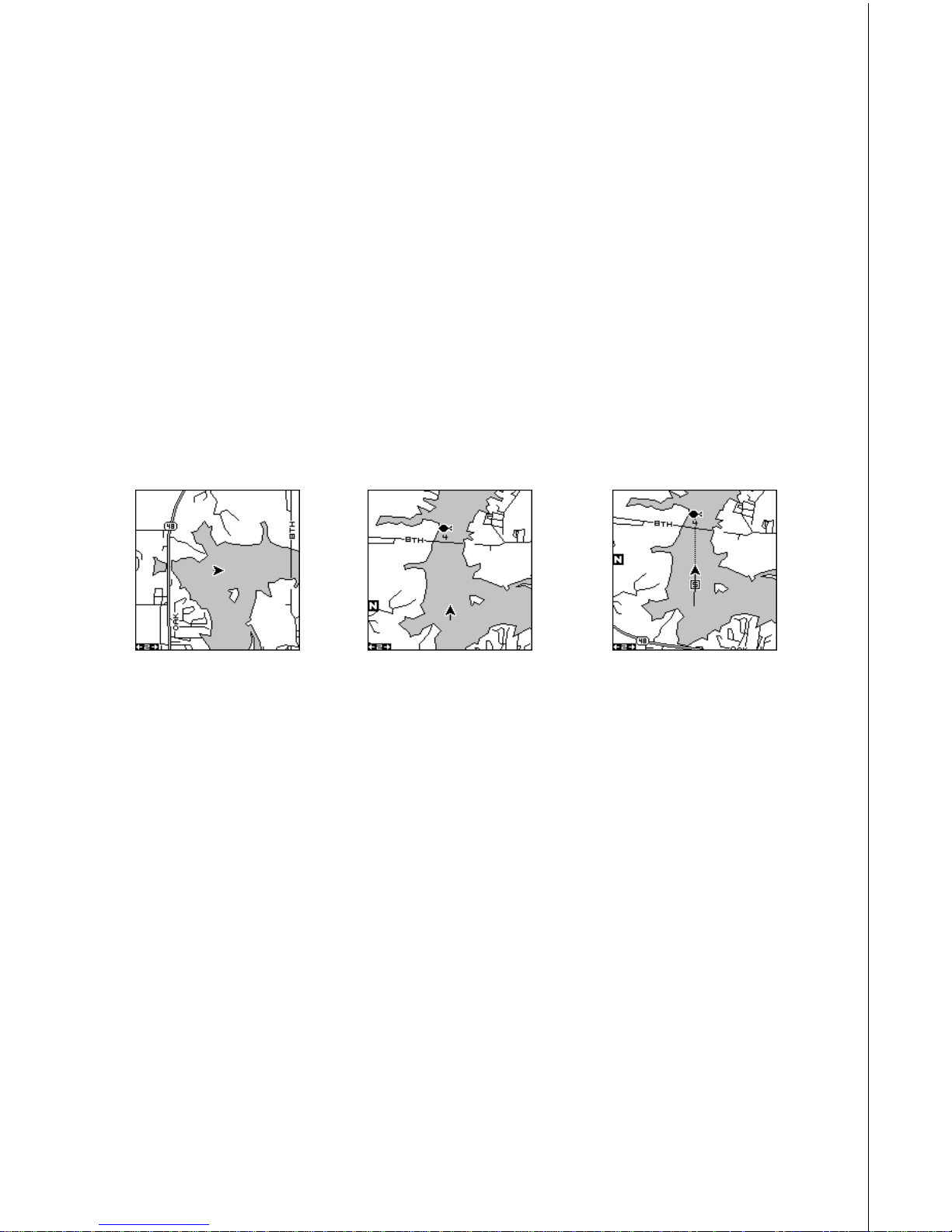
NORTH-UP TRACK-UP COURSE-UP
In the north-up view shown at left, we’re travelling east. In this view, the
present position indicator appears to move towards the right side of the
screen.
In the track-up vie w, the present position moves straight towards the top
of the display. A “N” shows to help y ou see which direction is north when
the track-up mode is on. Remember, in the track-up mode, the screen
rotates as you change direction. It always keeps your direction of travel
(track) heading tow ards the top of the screen.
In the course-up mode, the screen is lock ed into y our original bearing to
the recalled wa ypoint, regardless of your trac k.
To select the desired mode, first press the MENU key, select “MAP 1
SETUP”, then select “MAP OPTIONS”. Finally, select “ORIENTATION”
and press the right or left arrow key until the desired mode appears. Press
the EXIT key to er ase this men u.
22
Range Rings/Grid Lines
The map screen can be customized with rings
that are 1/4 of the range and/or grids that divide
the plotter into equal segments of latitude and
longitude. T o do this, press the MENU k ey , select
“Map 1 Setup”, then “Map Options”. Highlight the
desired option, then press the right arrow key to
turn it on. Press the EXIT k ey repeatedly to erase
the menus. The screen at right shows g rids.
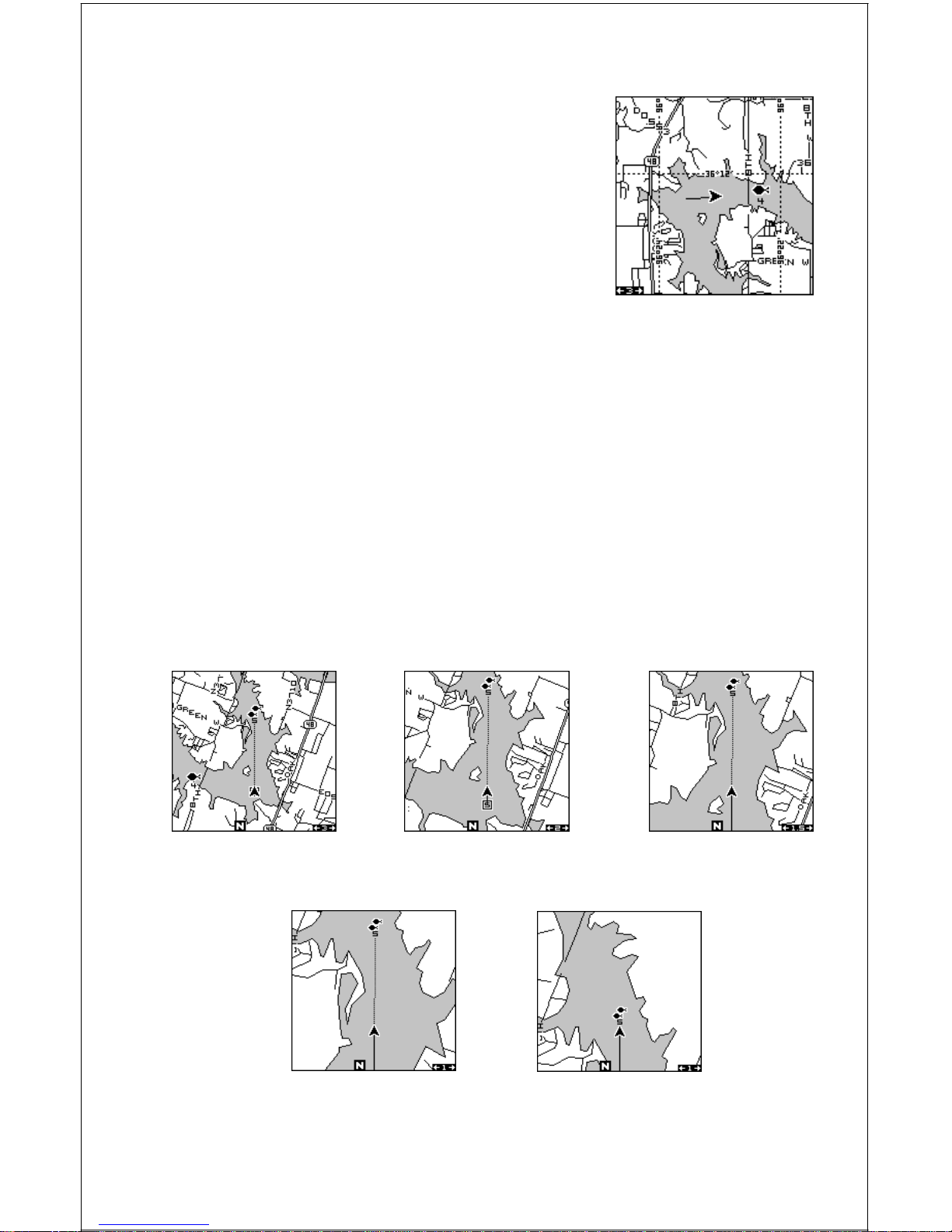
A UTOZOOM
This receiver has an autozoom f eature that eliminates much of the button
pushing that competitive units f orce you to make. It works in conjunction
with the navigation features. First, recall a waypoint. (See the waypoint
section for more inf ormation on navigating to a wa ypoint.) Then, with the
autozoom mode on, the unit zooms out until the entire course shows,
from the present position to the destination wa ypoint (recalled waypoint).
As you tra vel towards the destination, the unit automatically begins z ooming in, one zoom range at a time, k eeping the destination on the screen.
The screens below show a slice of the progression of a trip near a lake.
Screen number one is the start and is on the 3 mile range. Intermediate
stages progressively z oom in as it gets closer to the destination.
12 3
4
5
 Loading...