

Lowrance General information Pamplet, NMEA 2000 General Information Manual

1
Pub. 988-0154-172
Setup and Installation of
NMEA 2000 Networks
General Information
NMEA 2000 is a communication bus network specifically designed for
boats. This is an industry standard developed by the National Marine
Electronics Association(NMEA). To help you get the most out of this
technology Lowrance has introduced a line of products that can communicate over a NMEA 2000 network.
This instruction sheet outlines the basics of what it takes to create a
NMEA 2000 network. It also will explain how to use this network to
connect your Lowrance and LEI products and provide some tips on configuring and using the operational network.
Terminology
There are several key phrases you will need to know before we can explain how the NMEA 2000 system works. Some of these are technical
terms, some of them are names taken from the NMEA 2000 standard
and some of them are our own names developed for clarity. All of them
will help you understand what we are saying.
"NMEA 2000
Network" or "LowranceNET "
When we talk about the NMEA 2000 network we are talking about the
communications link between two or more devices that transfer NMEA
2000 information. "LowranceNET" is the NMEA 2000 networking system developed by Lowrance Electronics. Think of this as a computer
network or the phone wiring in your house. If you pick up a phone in
your living room you can hear someone talking into the phone in the
bedroom.
A NMEA 2000 network is a way to let more than one display unit "listen in" on the GPS antenna's conversation or to let more than one sonar
display unit overhear the messages being sent by a temperature sensor.
You can even view engine diagnostics and fuel level on digital gauges or
display units located anywhere on your boat.
If you have a Lowrance display unit with an LGC-2000 GPS module
installed then you have a NMEA 2000 network. The connectors and
cables that came with your LGC-2000 actually function as a dedicated
2
NMEA 2000 network passing GPS signal information along the network (that is, the extension cables) to the GPS display unit. This is a
very limited application of the term "network."
The other end of the scale is a network bus (described in the following
segment) built into your boat with nodes at intervals allowing you to
connect several GPS or sonar display units, temperature or water speed
sensors, digital gauges or any other NMEA 2000 device.
Such a network could display the temperature readings from two different sensors (one at the water surface and another in your live well)
as well as the GPS signal from an LGC-2000 and even the reading from
a fuel-flow sensor attached to your fuel line. The network could share
all of this information with a sonar-GPS combo display unit mounted in
the dash, a smaller sonar-only display unit at the stern and another up
on the bow by your trolling motor. All three display units attached to
the bus would have access to all of the sensor information from every
accessory attached to the network. The network design would look like
the one in the following diagram.
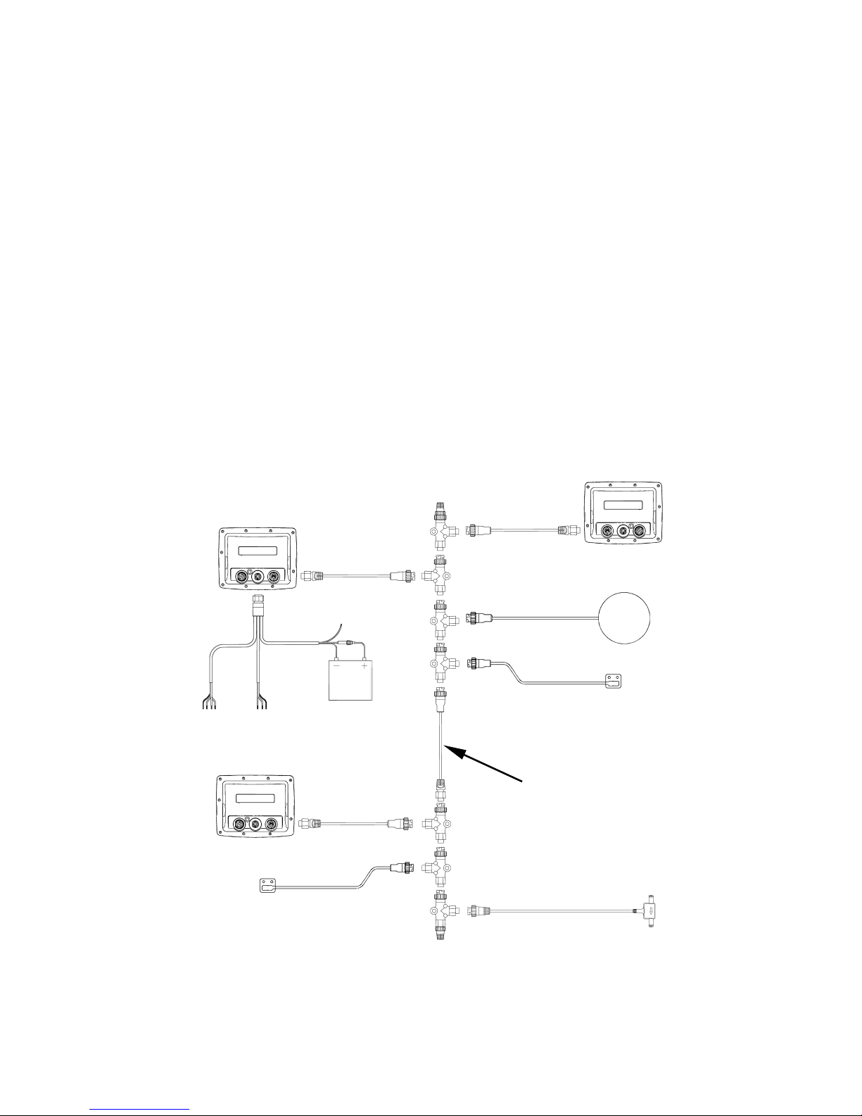
NMEA 2000 network with three sonar or sonar-GPS combo display
units, each receiving position information from the LGC-2000, tempera-
ture information from temp sensors at two different locations and fuel
use information from a fuel flow sensor.
Sonar-GPS
unit in dash
LGC2000
EP-35 temp sensor
in live well
EP-35 temp sensor
at water surface
Sonar unit
at bow
Sonar unit
at stern
EP-10 fuel flow sensor
25' extension
cable

3
That is the advantage of a NMEA 2000 network. Every display unit,
gauge or sensor attached to the network communicates with all the others.
Of course location, speed and temperature are not the only kinds of information that can be shared. Other capabilities include the ability to share
the amount of fuel remaining in your tanks, detailed engine information
such as oil pressure and fuel efficiency and much more.
NOTE:
You probably noticed there is no transducer mentioned in that list or
anywhere else in this document. The full sonar chart reading from a
transducer takes too much bandwidth for a NMEA 2000 network
which means sonar charts cannot be shared. Every sonar display
unit requires its own transducer to draw charts.
However, if you have a sonar display unit (with a working transducer) connected to the NMEA bus it will share the digital depth
with every other display unit on the network.
"NMEA 2000 Bus" or "Network Bus"
Technically, any physical cable properly installed and used to transfer
network information is a "network bus" but in our documentation we
use this term to refer to the standard manufacturer installation appearing in new boats. This network bus is an installed and operational
network cable running the length of your boat, already connected to a
power supply and properly terminated. Such a bus provides network
nodes at various locations around your boat.
"Network Backbone" and "Network Nodes"
A network bus is built of network nodes spread along a backbone. Network nodes are made by fitting T-shaped connectors into the backbone
(using the sockets on the sides) and attaching a display unit or sensor at
the bottom of the T.
If we stick with the earlier example, the T connectors along the length of
a boat are the equivalent of phone jacks spread throughout a house.
Phones in a home have to be connected to each other to communicate and
in the same way only sensors and display units plugged into the NMEA
network can share information. The backbone is like the phone wiring
that runs throughout a home; it connects these nodes.
Connections found in the middle of the bus will have one or more of these T
connectors with the backbone cables plugged into both sides. Connections
at the end of a network will have the backbone plugged into one side and a
terminator plugged into the other as shown in the following figure.
4
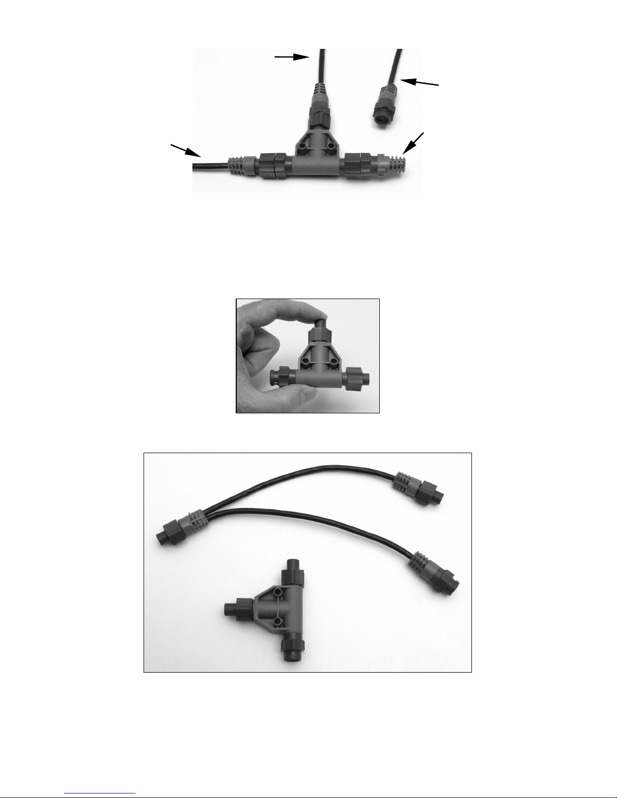
NMEA 2000 network node located at the end of a NMEA 2000 backbone.
All of the T connectors on your boat's network will probably be filled but
if you want to add another node to a working network just add a T connector from LEI (ordering information appears on the back page of this
booklet). If you are adding a Lowrance or LEI NMEA 2000 sensor it will
come with its own T connector making the process even easier.
This T connector allows you to add a device to your NMEA 2000 bus
creating a network node.
The "soft" T connector, shown above with a "hard" T connector, is another
option for connecting devices in a NMEA 2000 network. The soft T works
the same as a hard T. The soft T is used to install a network node in areas
were a hard T will not fit.
Backbone cable
(to rest of bus)
Cable from
sensor or
display unit
LEI or Lowrance
device needs an
open T.
Terminator at
the very end
of the bus
5
"Linear Architecture"
NMEA 2000 networks are designed using a linear architecture and it is
important for you to maintain this pattern whenever you modify your
network (such as adding nodes).
When we say "linear architecture" we are referring to the way the network's backbone is assembled and to the way you attach T connectors
along it. Note that every T connector has one female socket and two male
sockets. This means you could connect it in two different ways.
You could plug the sensor or display unit into the bottom of the T and
the backbone cable into the side of the T (as we recommend). You could
also plug the sensor or display unit into the side of the T and the backbone connection in the bottom of the T. The sockets would allow you to
make that connection but you would lose linear architecture. Consider
the following images.
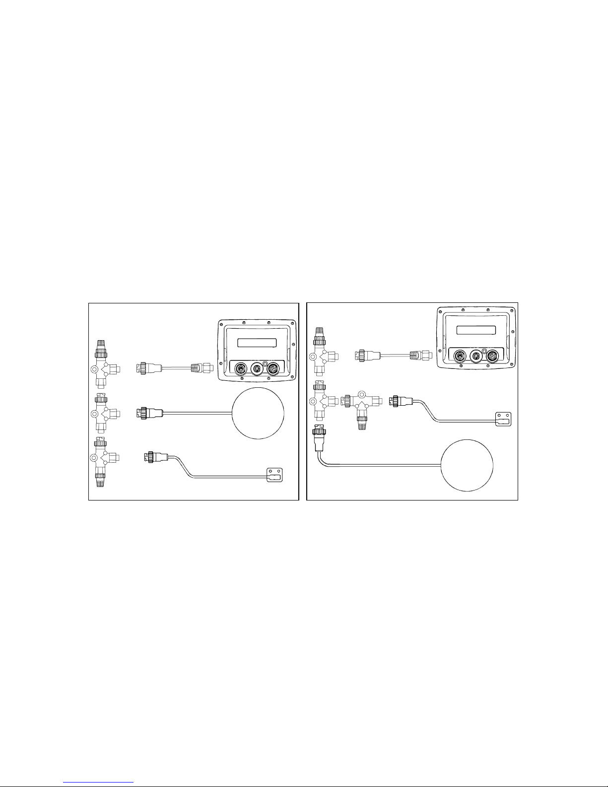
Two possible network designs. The design on the left maintains a linear
architecture while the one on the right does not. You should always
maintain linear architecture when building a NMEA 2000 network.
Both of the network designs in these images contain the same set of
components. Both networks are terminated and all of the connectors
are able to attach together. However, the design on the left is easier to
maintain and expand. It also allows you to make sure the two terminators are at the ends of the backbone. Since the system on the right is
non-linear there is not a clear end.
Always maintain linear architecture when modifying your network.
Just make sure to attach display units or sensors to the bottom of the T.
Attach the sides of the T to other T connectors, to backbone extension
cables or to terminators – nothing else.
LGC2000
LGC2000
EP-35
tem
p
sensor
EP-35
temp sensor
Sonar or GPS
display unit
Sonar or GPS
display unit
Correct architecture
Incorrect architecture
6
For reference purposes all of the example network designs you will find
in this document show networks built with a linear architecture.
Adding a Network Node
You can add a node anywhere along the network backbone where a connection already exists. This connection could be at the end of the network
(between a T connector and a terminator) between two T connectors, between a T connector and a backbone extension cable or between two extension cables. Wherever you want to add the new node simply separate
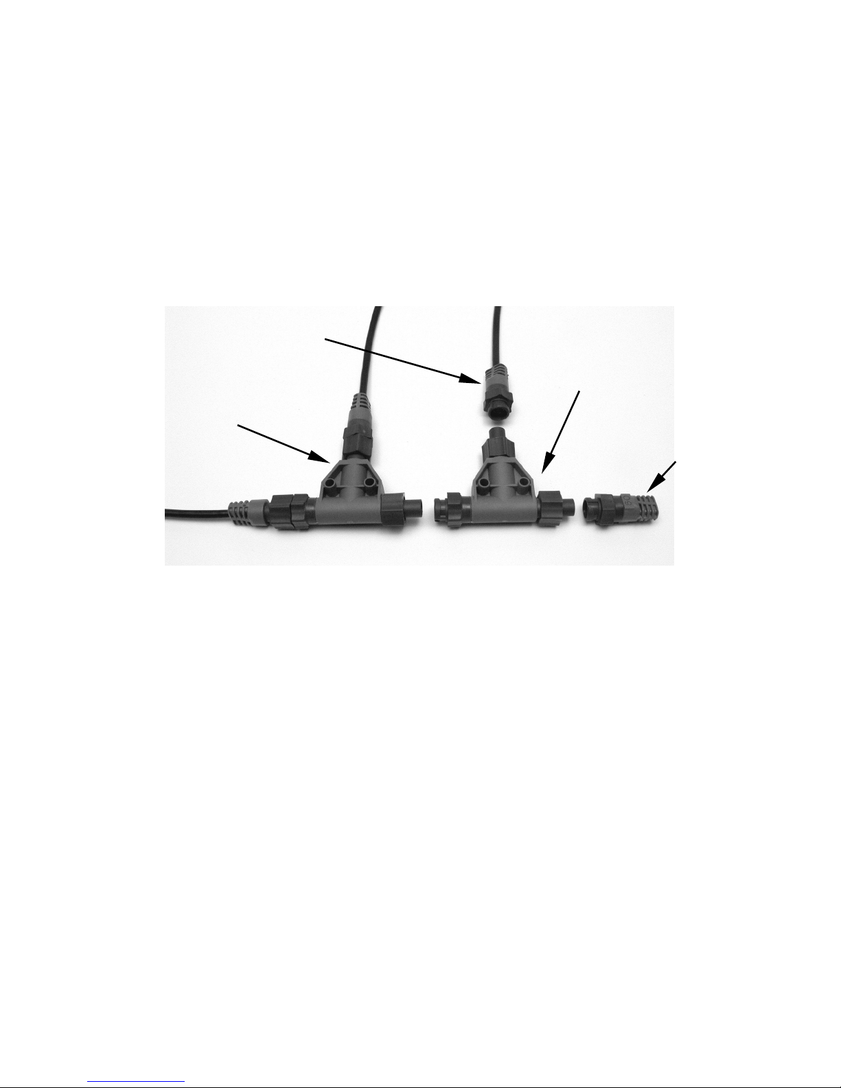
the sockets of the old connection and attach your new T connector between them.
Add a new device to a NMEA 2000 bus by attaching a T connector be-
tween two T connectors, between a T connector and the end terminator,
or between two backbone extension cables.
If you want to add a node at the end of the line (as shown in the previous
figure) remove the terminator from the very last connector, securely attach the new T connector, and attach the terminator on the new connector. Either method will allow you to add a device.
NOTE:
If your network only includes one terminator (such as the network
created when a single display unit is connected to an LGC-2000)
you will need to add a Node Kit before you can add additional network nodes. You only need to purchase a Node Kit once. After that
you can add nodes as described in the previous section.
Most manufacturer-installed networks will already have two terminators so a Node Kit will not be necessary.
Adding an Extension Cable
LEI provides LowranceNET extension cables in various lengths so that
you can position all of the items on your network exactly where you want
Existing network
node
Attach
terminator at
end of bus.
Add T-shaped connector to add device
to bus (maintaining
linear architecture).
Lowrance or LEI device connects to new T connector.
 Loading...