

Lotus Europa Twin Cam Owner's Manual
LOTUS EUROPA TWIN CAM
COMPETITION MANUAL
PREPARED BY: JENSEN MOTORS, INC.
19200 SUSANA RD.
COMPTON, CALIF. 90221

( i )
FOREWORD
Modifications of the type described in this booklet and/or the use of the Lotus Europe Twin-Cam
for competition render the vehicle warranty null and void. Jensen Motors, Inc. and/or Lotus Cars,
Ltd. will not be held responsible for any damage or injury, which may occur in the following of
any procedure or changes outlined in the following text.

( ii )
CONTENTS
FOREWORD............................................................................................... ( i )
INTRODUCTION....................................................................................... ( ii )
Section
CHASSIS...................................................................................................... 1
SUSPENSION AND STEERING................................................................ 4
BRAKING SYSTEM................................................................................... 11
COOLING SYSTEMS (WATER, OIL AND DRIVER)............................. 12
ENG I NE..................................................................................................... 14
TRANSMISSION AND CLUTCH.............................................................. 15
BODY........................................................................................................... 21
ELECTRICAL.............................................................................................. 21
FUEL SYSTEM............................................................................................ 22
GENERAL.................................................................................................... 22
SETTING-UP CAR...................................................................................... 23
SPECIFICATIONS....................................................................................... 24

( iii )
INTRODUCTION
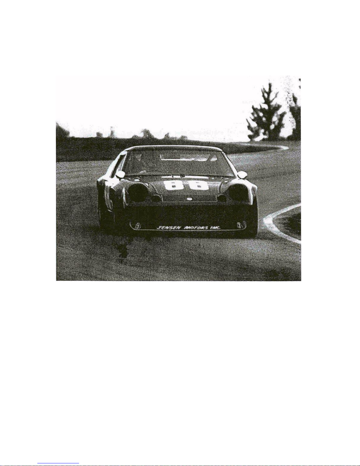
The advanced design and performance of the road equipped Lotus Europa Twin-Cam
precludes the necessity for extensive modifications for track purposes. The modifications made
were mainly as a result of necessary compromises incorporated in the road car to conform to
regulations and to achieve an acceptable level of creature comfort. Other modifications were
necessary to increase the safety of the car and driver while racing.
We do not claim the modifications and changes mentioned in this booklet to be a
complete listing, or to be the ultimate in development; but merely those which we have proved to
be effective in campaigning the car in SCCA production sports racing. While we would not
knowingly recommend changes, which would not be legal under the SCCA production sports
rules, it is the responsibility of each driver to ensure that his vehicle conforms to the applicable
competition regulations.
We would like to wish you every success in your competition endeavors with the Lotus
Europa Twin-Cam, and if technical assistance is ever required please do not-hesitate-to contact
the writer.
Colin Ham
Service Engineer
Jensen Motors, Inc.
19200 Susana Road
Compton, California 90221

1
CHASSIS
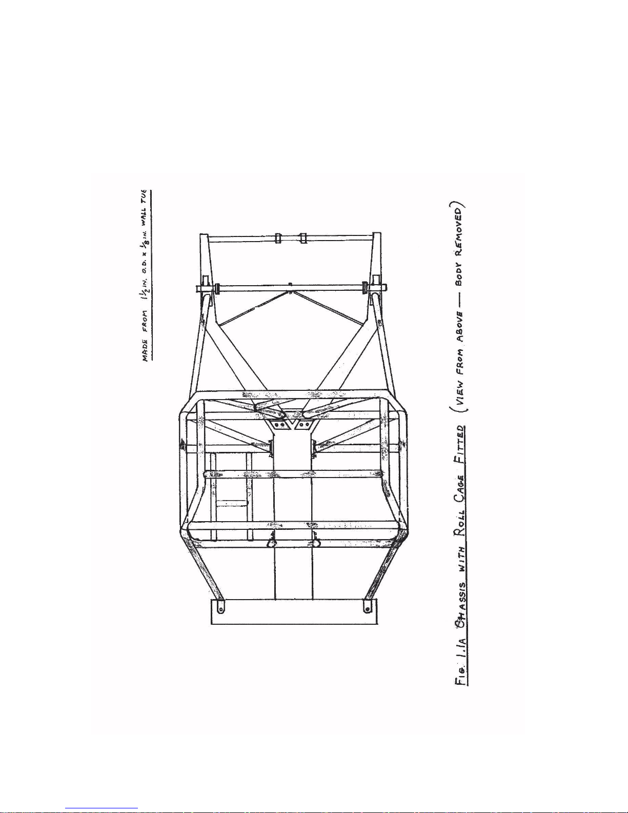
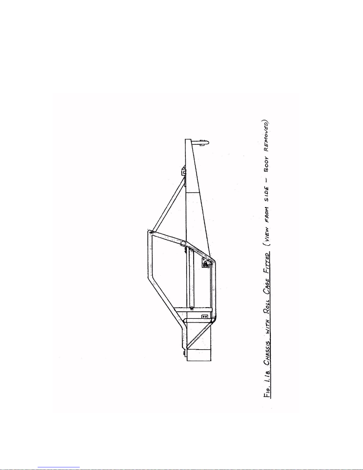
In order to provide maximum safety for the driver a full roll cage was added to the basic
chassis. The backbone type design of the chassis necessitated a very unorthodox and intricate
cage. (See Figure 1.1A and 1.1B)
The cage was bolted rather than welded to the chassis at several points to allow removal
of the body from the chassis, although the cage could not be removed intact from the body. The
two main roll over hoops were bolted to the chassis main backbone with bracing stays forward to
the front crossmember and rearward adjacent to rear spring supports. Threaded reinforcement
plates were added to the chassis at the attachment points. The rear spring supports were
reinforced and welded rather than bolted to the chassis. This necessitated
fabrication of a removable rear chassis crossmember to facilitate engine removal.
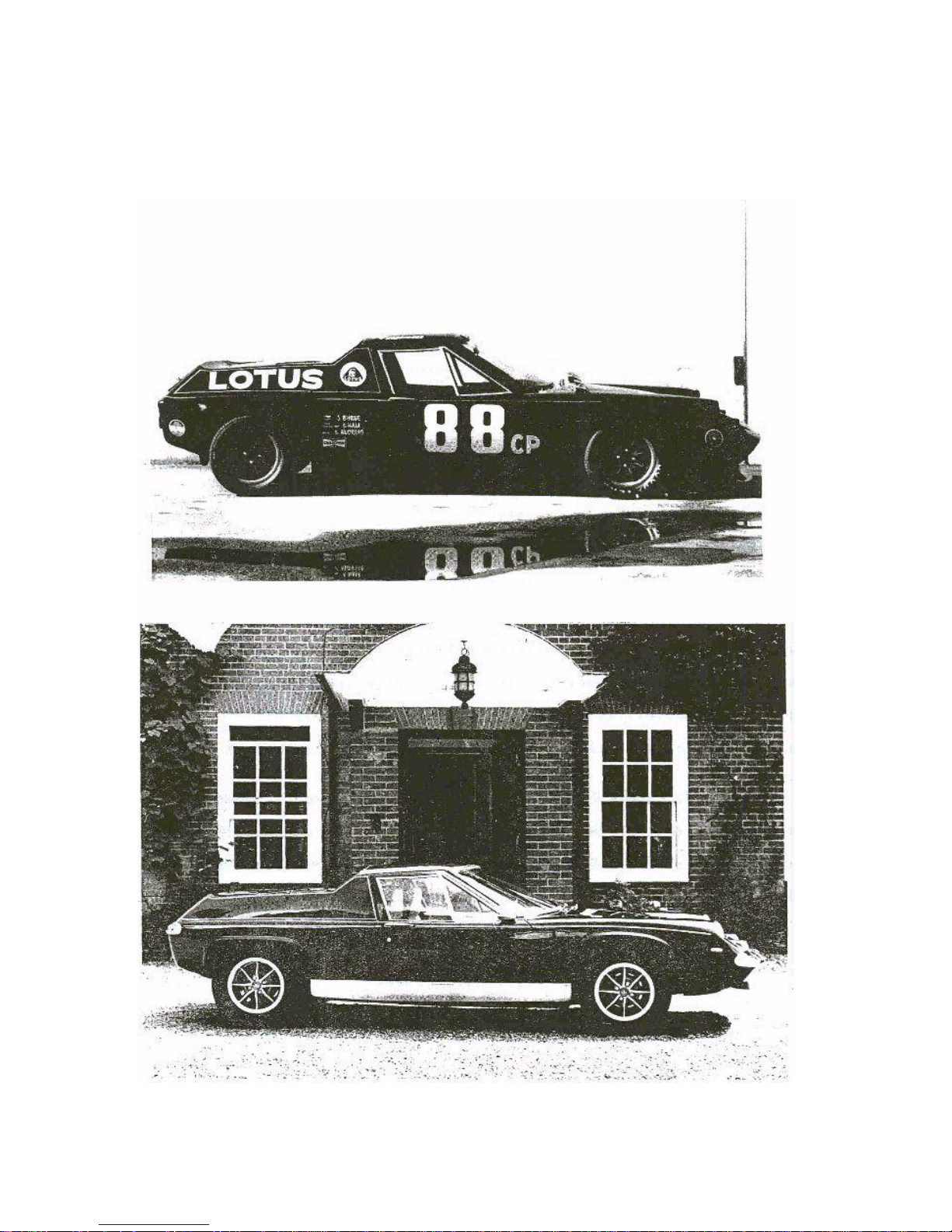
The complete cage was enclosed within the bodywork in order to maintain the
appearance and the good aerodynamic characteristics of the car.
Torsional stiffness of the front crossmember-backbone intersection was increased by
calculated positioning of roll cage attachment points. All welded joints on the standard chassis
were filled to give continuous welds for added strength.
No attempt was made to lighten the chassis as it was considered to be as light as practical.
2
3

4
SUSPENSION
Front Suspension
The front suspension uprights and hubs were from the Triumph GT6 Mk II!, to enable
the use of larger 9 3/4 in. d i3meter brake discs and calipers from the same car.
The suspension arms inboard rubber bushings were changed to "Nylatron" (Holy
Disulphide) bushings to eliminate any uncontrolled movement in the suspension. All bushings
are identical and eight are needed per car. The dimensions are: length=l.40 in., diameter=l.061 in.
with bore=0.502 in. The bushings are a "press-fit" in the suspension arms.
The suspension was lowered by fitting shorter front springs together with fully adjustable
Koni shock absorbers. It should be noted, that due to the large deflections required in relation to
spring length, special thin vanadium spring wire must be used to prevent the spring becoming
coil bound on full bump. The shock absorber bump rubber must be shortened approximately one
inch to prevent fouling on full bump.
With the lowered suspension settings, it is necessary to decrease the negative camber of
the front wheels. This was achieved by moving the lower suspension arms outer pivot point
inwards. This was carried out by slotting the existing holes in the arms and installing drilled
plates to locate pivot in desired position (0.158 in. per l° of camber change). The plates fitting
securely in channel of lower suspension arms.
5
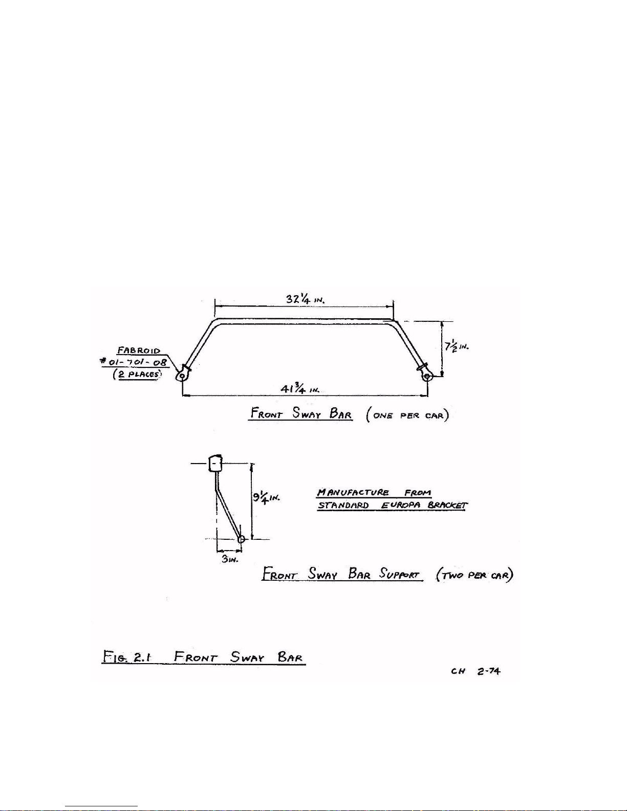
The optimum size of the front sway bar was found to be 7/8 in. in diameter. The bar was non-
adjustable and installed in approximately the stock location. The sway bar had Fabroid rod end
spherical bearings on each end and was attached to the lower shock absorber mounting bolts
using spherical bearings. The standard location arms were shortened to compensate for the
lowered suspension. (See Figure 2.1) All fine suspension tuning was achieved by use of an
adjustable rear sway bar.
6
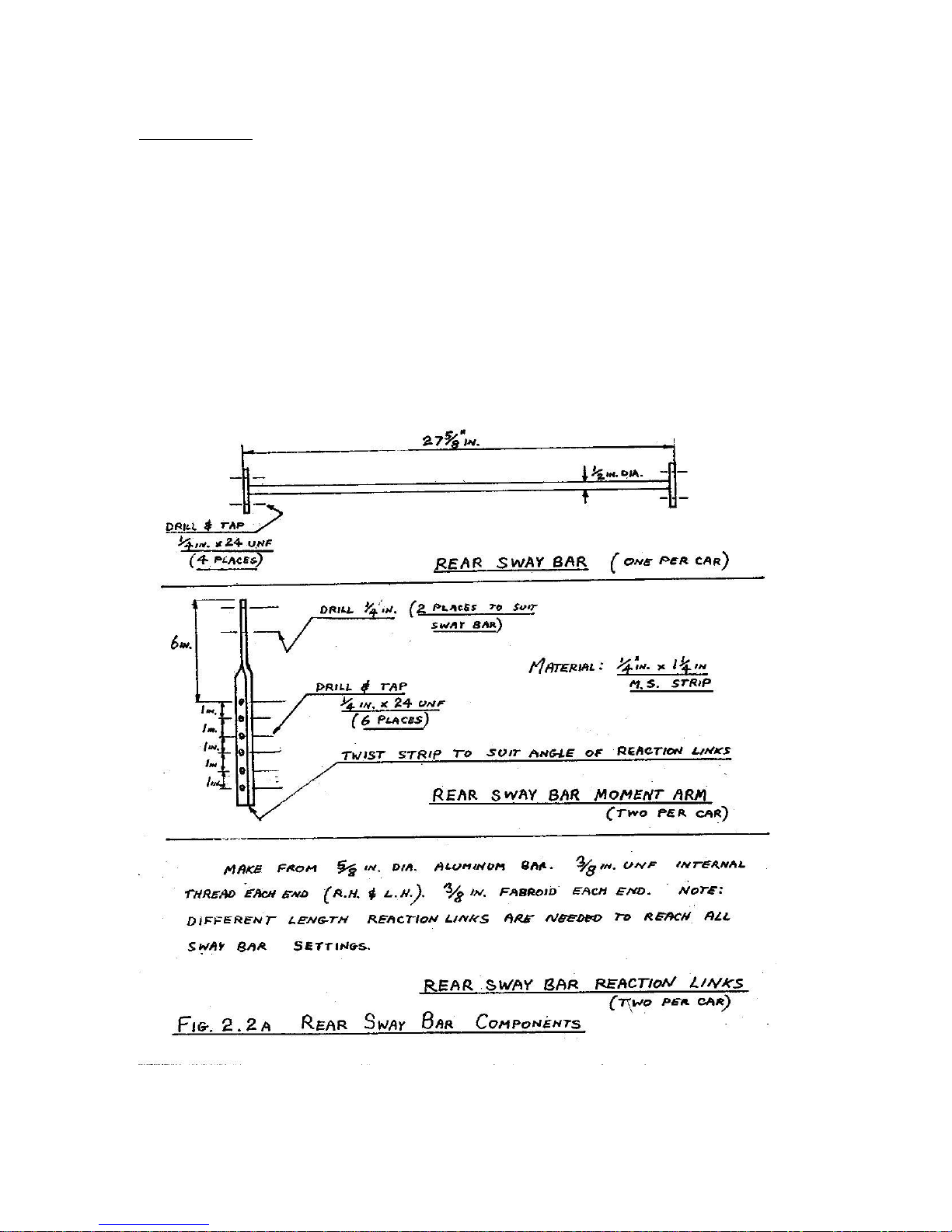
Rear Suspension
The modifications made to the rear suspension consisted of mainly eliminating rubber
mounting bushings and strengthening chassis attachment points. Full adjustment capability was
also provided. An adjustable sway bar was added to enable fine suspension adjustments to be
made to compensate for different circuits. (See Figure 2.2A and 2.2B)
 Loading...