


Europa

----------------------------------------------------------------------------------------Section Updated: 10/25/2007 4:05 AM at http://www.lotus-europa.com ----------------------------------------------------------------------------------------
SECTION A
CHASSIS UNIT
Section Description Page No
A.1 GENERAL DESCRIPTION 3
A.2 MAINTENANCE 3
A.3 ACCIDENT DAMAGE 5
A.4 CHASSIS UNIT - REPLACEMENT 5

PAGE 2 SECTION A – CHASSIS UNIT
----------------------------------------------------------------------------------------Section Updated: 10/25/2007 4:05 AM at http://www.lotus-europa.com ----------------------------------------------------------------------------------------

SECTION A – CHASSIS UNIT PAGE 3
----------------------------------------------------------------------------------------Section Updated: 10/25/2007 4:05 AM at http://www.lotus-europa.com ----------------------------------------------------------------------------------------
ILLUSTRATIONS
Fig. No. Description Page No.
1 The Components of the Chassis Unit. 2
2 General Arrangement of the Chassis Unit. 4
------------------------------------------------------------------------------------------------------------------------------------------------------------------------------------
A.1 - GENERAL DESCRIPTION.
The chassis unit is of the fabricated backbone type with a bar section spine splayed and braced at the
rear to support the engine/transmission unit. A box section cross member added onto the front of the
backbone carries the front suspension pivots and upper spring mountings. Welded in pivot pins provide
the mounting points for the front lower wishbones whilst the upper wishbones are located by detachable
pivot pins passing through bushes welded into the cross member. It should be noted that all the
suspension loadings are taken by the chassis and whilst the chassis unit possesses great tortional rigidity,
the ultimate strength of the vehicle as a whole is dependent on the chassis attachment to its body.
Construction of the chassis is in mild steel sheet with local stiffeners, either electrically or acetylene
welded as applicable. This latter welding process is the only method approved in Service and is: - 'C0
2
Inert Gas'. The front cross member serves a dual purpose and acts as the mounting for the steering unit.
The power and final drive unit is flexibly mounted within the chassis structure. The power unit is
supported by two brackets, each carrying a rubber insulation block situated one each side of the cylinder
block. The rear of the unit is supported by a welded in tubular cross member also, incorporating its
insulating block at the rear of the gearbox and bridging the chassis at this point. The radius arms are
pivoted at the forward end of the splayed sides of the chassis. Each radius arm mounting incorporates a
flexible component in rubber, designed to assist in sound and vibration insulation.
-----------------------------------------------------------------------------------------------------------------------------------------------------------------------------------A.2 - MAINTENANCE.
A minimum of maintenance is required on the chassis unit itself. Occasional checks should be made to
see that all body attachments points are tight and that ancillaries attached to the chassis units are not
loose. Checks should also be made to see that the handbrake fulcrum pivot is functioning and an
inspection of all suspension attachment points for tightness and ease of operation.

PAGE 4 SECTION A – CHASSIS UNIT
----------------------------------------------------------------------------------------Section Updated: 10/25/2007 4:05 AM at http://www.lotus-europa.com ----------------------------------------------------------------------------------------

SECTION A – CHASSIS UNIT PAGE 5
----------------------------------------------------------------------------------------Section Updated: 10/25/2007 4:05 AM at http://www.lotus-europa.com ----------------------------------------------------------------------------------------
A.3 - ACCIDENT DAMAGE
Economics, available repair facilities and delivery circumstances provide the criteria for assessment of a
chassis repair or replacement. It follows from this that when parts are subjected to an ABNORMAL load
the possibility of failure is increased and indeed incipient failure may be initiated. Incipient failure is the
more dangerous form, as, having no visible effect, the part may be assumed to be in good condition and
then fail in ensuing normal service.
Consequently, whenever a car suspension or steering is damaged, consideration should be given to
secondary or shock damage.
For example, in the case of the front suspension, both steering mechanism and chassis mountings should
be carefully examined for both misalignment and microcracks. Even when no damage is apparent to the
mounting pins, if the wishbones have been damaged it is strongly advised that a new chassis be fitted.
Should the mounting pins be damaged or bent, (however slightly) A NEW CHASSIS MUST BE
FITTED. These principles must always apply where driver safety is the prime consideration.
Inspection should be made of engine and gearbox mounting points where a vehicle has been involved in
impact. As the unit may have traveled forward, distortion could have occurred; check for broken welds,
etc.
Reference should be made to the critical dimensions shown on the general arrangement drawing (Fig.2)
for a complete damage assessment where any impact has occurred. Diagonal checks from four points
will show any misalignment.
Where broadside impacts or fire have created severe distortion conditions a replacement unit is essential.
Patching as a repair expedient is not recommended, whilst stretching can only be achieved with heat on
the buckled surfaces of larger sections.
-----------------------------------------------------------------------------------------------------------------------------------------------------------------------------------A.4 - CHASSIS UNIT - REPLACEMENT
In the event of a complete chassis 'write-off', it will be necessary to fit the replacement unit to a body
shell. It may be found that the body shell mounting points may not exactly match the mounting holes on
the new chassis flanges. This condition is due to slight contraction of the body materials during its
manufacturing and curing processes. Whilst every effort is made to keep the centre dimensions of all the
bobbins within reasonable limits, it is recommended that the body be 'offered up' to the chassis before
any assembly is undertaken. A visual check should be made for any holes that may not align with their
respective mounting points in the body shell. These may be elongated just sufficiently to receive the
mounting bolts.
It is suggested that prior to assembling the body unit to the chassis the fitting of certain components at
this juncture will facilitate assembly.
These are listed below: (All Torque loadings are given in 'Technical Data').
A/- Chassis-Build, Standard Phase II Model.
Place chassis on trestles, right way up.
Remove 24 pieces of masking tape. Remove 'horseshoe' from handbrake cable.
Fit long brake pipe, surround by 2 grommets.
Thread loop of handbrake cable through slit in chassis. Retain the looped cable by fitting 2 clips.
Replace horseshoe onto looped cable.
Fit 4 way union to front chassis, separated from chassis by 4 packing washers.

PAGE 6 SECTION A – CHASSIS UNIT
----------------------------------------------------------------------------------------Section Updated: 10/25/2007 4:05 AM at http://www.lotus-europa.com ----------------------------------------------------------------------------------------
Thread intermediate handbrake cable through 'horseshoe'. Pull out at rear end and attach locknuts and
spring. Open free end of spring for entry in chassis hole.
Fit master cylinder to front chassis, attach with retaining plate, washers, and 2 Nyloc nuts.
Re-enter cable in backbone and locate spring. Re-bend end of spring to original form.
Attach handbrake cable to both chassis forks, 3 spring clips per fork.
Form end of long brake pipe to fit front 4 way union, 3 bends. Torque 7 lb/ft.
Fit two engine mountings, 4 bolts, Nyloc nuts/mounting. On RH mounting attach earth strap -chassis to
engine. Fit 2 radius arm mountings, 2 bolts, Nyloc nuts/mounting.
Attach master cylinder brake pipe to 4 way union, 4 bends.
Torque 7 lb/ft. (non servo vehicle only).
Attach LH and RH brake pipes to 4 way union. Torque 7 lb/ft.
Tap out 2 chassis seat belt mounting points, 7/16" UNF.
Insert 4 grommets in rear end plate (5 on servo vehicles). The large gear linkage grommet has upper part
removed and later used for sealing gear lever.
Large grommet is attached to chassis with DUNLOP S 758 adhesive.
Insert grommet in chassis adjacent to heater outlet. Attach 3 grommets in front chassis (or 4 on servo
vehicle) and blank-off unused holes with black adhesive tape.
Clean out 8 brake clip holes: 4 on underside of backbone, 2 on each chassis fork. Attach long brake pipe
to chassis with 4 spring clips and 2 screwed clips. Bend pipe to suit form of chassis.
Attach 2 flexible heater hoses to rear chassis outlets with hose clips.
Fit 4 way pressure switch union to RH rear chassis fork, separated from chassis by 6 packing washers.
Remove masking tape off steering rack.
Attach steering rack to chassis with 2 brackets, (2 bolts/brackets), bolt heads placed within chassis box
section.
Attach slave steering column to rack to ensure clearance when tightening rack assembly. Ensure Bundy
pipes are free from brackets.
Connect free end of long brake pipe to the pressure switch union.
Torque: 7 lb/ft.
Connect 'U' shaped brake pipe to the pressure switch union.
Torque: 7 lb/ft.
Fit 2 water transfer pipes within chassis backbone. Smear grommets with liquid soap to assist movement
of pipe.
Servo vehicle only:
Bend 3/8" Bundy pipe on jig (vacuum supply rear).
Cut vacuum hose into three lengths 5 ½", 9", and 11".
Attach 2 hose clips to 5 ½" and 9'' hoses and 1 clip to the 11" hose.
Smear ends with Castrol Rubber Grease.
Attach 'T' piece to the 5 ½" hose and connect the 60", 3/8" Bundy pipe to the rear, 3/8" Bundy pipe with
the 9" hose.
Insert 'front and rear' vacuum supply pipe in chassis backbone.
Attach 3/8" Bundy pipe to LH water transfer pipe with 3 grommets. Separate Bundy pipe from transfer
pipe by black adhesive tape.
Attach 'T' piece hose to rear 3/8" Bundy pipe and the 11" hose to the front end of the 3/8" Bundy pipe.
Attach RH water transfer pipe and battery earth lead to RH chassis fork.
Fit header tank to chassis and attach LH transfer pipe to header tank with hose and 2 clips (hose and
clips sub-assembly).
Collect engine number and transmission number from Works Order. Stamp body, plate and chassis.
Chassis number stamped on RH rear chassis fork.

SECTION A – CHASSIS UNIT PAGE 7
----------------------------------------------------------------------------------------Section Updated: 10/25/2007 4:05 AM at http://www.lotus-europa.com ----------------------------------------------------------------------------------------
Where a radio interference suppression kit is installed, the following additional operations are required:
Drill one hole, ¼" diameter on each rear chassis fork.
Fit earthing braid tags to each chassis fork.
Fit flexible brake pipe to RH chassis fork, tighten to bracket and brake pipe. Torque: 10 lb/ft.
Fit flexible brake pipe to LH chassis fork, tighten to bracket and brake pipe. Torque: 10 lb/ft.
Sub-assemble nylon ball to gear lever with 2 circlips.
Sub-assemble 2 washers to gear lever grommet, smear with Castrol Rubber grease and fit to chassis.
Sub-assemble gear change connecting link to gear lever, with lower retaining plate in position on gear
lever. Joint affected by shoulder screw, nylon washers and Nyloc nut. Threaded stud on free end of
connecting link in downward position w.r.t. final position of gear linkage.
Insert gear linkage in chassis, position, and lock in place with retaining plate: 4 off 4 BA screws and
spring washers. Attach rubber grommet over gear lever.
Insert speedometer cable in chassis, adjacent to heater outlet connection:
Thread out of chassis along RH fork to RH gearbox mounting. Coil cable within chassis and leave on
RHS of gear linkage, so cable end just protrudes by heater connections.
Insert heater and choke cable assembly through oval backbone hole, guide through grommets, choke
cable RHS, heater cable LHS.
Apply Dunlop adhesive S 919 to chassis.
Attach 2 pieces of pre-formed felt to chassis. Ensure even application of felt. Trim felt to fit gear lever
retaining plate.
Obtain front suspension parts: LHS, RHS.
Upper and Lower Wishbones - Wheel Hub Assembly - Bushes - Anti-roll bar - Nyloc Nuts - Bolts Washers - Damper Assembly.
Position parts at front of chassis.
FRONT SUSPENSION RHS
Attach leading and trailing lower wishbones to RHS mounting spindle.
Retain by applying washer and Nyloc nut, leaving loose.
Assemble upper trailing wishbone, damper unit and upper leading wishbone to stud. Stud head
positioned at rear of front chassis section.
Locate damper unit in lower wishbone mounting point with 1 bolt inserted from front. Add washer and
Nyloc nut, leaving loose.
Attach wheel hub assembly to upper wishbone with 2 bolts, washers, and Nyloc nuts. Bolt head at front
and nuts left loose.
Attach wheel hub assembly to lower wishbone with 1 bolt, washer and Nyloc nut. Bolt-head at front and
nut left loose.
Connect steering link to wheel hub assembly, 1 Nyloc nut and washer.
FRONT SUSPENSION LHS
Repeat the above operations for LHS.
Attach LHS flexible brake pipe from wheel hub assembly to chassis bracket and tighten to Bundy pipe.
Torque 10 lb/ft.
Repeat the same operation for RHS.
Remove locknuts, cup, bush and cup off anti-roll bar location on underside of each damper unit, LHS
and RHS. Apply anti-roll bar to one damper unit mounting, secure with cups, bush and locknuts (leave
nuts loose). Compress free end of anti-roll bar to other damper mounting point, retain with cups, bush
and locknuts. (Leave

PAGE 8 SECTION A – CHASSIS UNIT
----------------------------------------------------------------------------------------Section Updated: 10/25/2007 4:05 AM at http://www.lotus-europa.com ----------------------------------------------------------------------------------------
nuts loose). Locate anti-roll bar support struts on upper wishbone mountings LH and RH and secure
with washers and Nyloc nuts.
Tighten all suspension - anti-roll bar nuts and bolts.
Apply underseal compound to black masking tape at front of chassis.
Attach closing plate to front of chassis.
Check sub-assembled engine unit.
Attach silencer to engine unit with 2 brackets.
Tighten exhaust pipe clip and manifold clamp.
Attach bottom links to LH and RH gearbox brackets. Insert bushes.
Position gear change rod along RHS of engine.
Lift engine off trolley and locate in chassis mounting brackets.
Bolt engine to RH engine mounting bracket, leave nuts loose.
Bolt engine to LH engine mounting bracket, leave nuts loose.
Further assembly is divided between upper and lower builds: -
LOWER BUILD
Attach radius arm - drive shaft - wheel hub sub-assembly to RHS resilient chassis mounting.
Attach flexible brake pipe to bracket on RH radius arm and tighten to Bundy pipe. Torque 10 lb/ft.
Locate RH drive shaft on gearbox spline shaft. Lock in place with sub-assembled 'mecanindus' tension
pins.
Repeat the three above operations for LHS.
Attach rear suspension cross-beam to chassis.
Locate damper unit in RH cross-beam mounting. Attach lower end of wheel hub unit. Connect lower
link to wheel hub unit. Leave all nuts loose.
Attach handbrake cable to RH radius arm bracket. Cable not connected to brake unit.
Repeat the above two operations for LHS.
Tighten rear suspension nuts - 10 off. [1]
Attach rear brake drums.
UPPER BUILD
Tighten engine-gearbox unit to flexible mounting brackets.
Connect earth strap to RHS of engine block.
Connect gear crossover linkage.
Connect flexible water hoses:
A) Heater hose to heater control valve.
B) Header tank to engine block.
C) Heater control valve to engine block.
D) Heater hose to engine block.
E) RH transfer pipe to engine block.
Where servo assisted brakes are fitted, cut carburettor manifold vacuum hose and insert 'T' piece.
Connect choke control cable to carburettor.
Connect heater control cable to control valve.
Connect speedometer angle drive to cable end. Insert gearbox end cover, and lock in position.
Re-route H.T. ignition coil lead.
Stick rubber pad to RH chassis battery support bracket.
Coat chassis number with Plus Gas Formula 'B'.

SECTION A – CHASSIS UNIT PAGE 9
----------------------------------------------------------------------------------------Section Updated: 10/25/2007 4:05 AM at http://www.lotus-europa.com ----------------------------------------------------------------------------------------
B/- Chassis–Build, Federal Specification Phase II Model.
Place chassis on trestles, right way up.
Remove 24 pieces of masking tape.
Remove 'Horseshoe' from handbrake cable.
Flt long brake pipe, surround by 2 grommets.
Thread loop of handbrake cable through slit in chassis. Retain the looped cable by fitting 2 clips.
Replace 'horseshoe' onto looped cable.
Bolt 'blanked' three way union to RHS of front chassis, separated from chassis by 4 packing washers.
Thread intermediate handbrake cable through 'horseshoe'. Pull out at rear end and attach locknuts and
spring. Open free end of spring for entry in chassis hole.
Bolt three way union to LHS, separated from chassis by 4 packing washers.
Bend end of long brake pipe to fit RH union, 3 bends. Torque 7 lbs/ft.
Re-enter handbrake cable in backbone and locate spring. Re-bend end of spring to original form.
Attach LH brake pipe to LH union, straight pipe. Torque: 7 lbs/ft.
Attach RH brake pipe to LH union. 4 bends. Torque : 7 lbs/ft.
Attach handbrake cable to both chassis forks, 3 springs clips per fork.
Clean out 8 brake clip holes, 4 on underside of backbone, 2 on each chassis fork. Drill extra hole for
screwed clip at intersection of backbone and RH chassis fork.
Fit 2 engine mountings, 4 bolts, Nyloc nuts, washers/mounting. On RH mounting attach earth strap chassis to engine.
Fit two radius arm mountings, 2 bolts, Nyloc nuts, washers/mounting.
Attach long brake pipe to chassis with 4 spring clips and two screwed clips.
Bend pipe to suit form of chassis.
Fit 4 way pressure switch union to chassis, separated from chassis by 6 packing washers.
Tap out 2 chassis seat belt mounting points, 7/16" UNF.
Connect free end of long brake pipe to the pressure switch union.
Torque: 7 lbs/ft.
Fit 4 grommets to rear end plate. The large gear linkage grommet has upper part removed and later used
for sealing gear lever. The large grommet is attached to chassis with Dunlop S 758 adhesive.
Insert grommet in chassis adjacent to heater outlet. Attach 3 grommets in front chassis and blank-off
unused holes with black adhesive tape.
Attach 2 flexible heater hoses to rear chassis outlets with hose clips.
Connect 'U' shaped brake pipe to the pressure switch union.
Torque: 7 lbs/ft.
Remove masking tape off steering rack. Attach steering rack to chassis with 2 brackets
(3 bolts/bracket), bolt heads placed within chassis box section.
Attach slave steering column to rack to ensure clearance when tightening rack assembly.
Ensure Bundy pipes are free from bracket.
Connect 'V' shaped brake pipe to the pressure switch union. Attach to chassis with 3 spring clips.
Torque: 7 lbs/ft.
Fit 2 water transfer pipes within chassis backbone. Smear grommets with liquid soap to assist movement
of pipe.
Fit header tank to chassis and attach LH transfer pipe to header tank with hose and 2 clips.
(Hose and clips sub-assembled).
Attach RH water transfer pipe and battery earth lead to RH chassis fork.
Collect engine number and transmission number from Works Order. Stamp body plate and chassis.
Chassis number stamped on RH rear chassis fork.

PAGE 10 SECTION A – CHASSIS UNIT
----------------------------------------------------------------------------------------Section Updated: 10/25/2007 4:05 AM at http://www.lotus-europa.com ----------------------------------------------------------------------------------------
Locate anti-roll bar support struts on upper wishbone mountings. LH and RH and secure with washers
and Nyloc nuts.
Tighten all suspension - anti-roll bar nuts and bolts.
Apply underseal compound to black masking tape at front of chassis.
Check sub-assembled engine unit.
Attach silencer to engine unit with 2 brackets. Tighten exhaust pipe clip and manifold clamp.
Attach bottom links to LH and RH gearbox brackets, insert bushes.
Position gear change rod along RHS of engine.
Lift engine off trolley and locate in chassis mounting brackets.
Bolt engine to RH engine mounting bracket, leave nuts loose.
Bolt engine to LH engine mounting bracket, leave nuts loose.
Further assembly is divided between upper and lower builds: -
LOWER BUILD.
Attach radius arm - drive shaft - wheel hub and assembly to RHS resilient chassis mounting.
Attach flexible brake pipe to bracket on RH radius arm and tighten to Bundy pipe. Torque: 10 lbs/ft.
Locate RH drive shaft on gearbox spline shaft. Lock in place with sub-assembled 'mecanindus' tension
pins.
Repeat the above three operations for LHS.
Attach rear suspension cross-beam to chassis.
Locate damper unit in RH cross-beam mounting. Attach lower end of Wheel hub unit. Connect lower
link to wheel hub unit. Leave all nuts loose.
Attach handbrake cable to RH radius arm bracket. Cable not connected to brake unit.
Repeat the above two operations for LHS.
Tighten rear suspension nuts - 10 off. [1]
Attach rear brake drums.
UPPER BUILD.
Tighten engine-gearbox unit to flexible mounting brackets.
Connect earth strap to RHS of engine block.
Connect gear cross-over linkage.
Connect flexible water hoses: A) Heater hose to heater control valve.
B) Header tank to engine block.
C) Heater control valve to engine block.
D) Heater hose to engine block.
E) RH Transfer pipe to engine block.
Connect choke control cable to carburettor.
Connect heater control cable to control valve.
Connect speedometer angle drive to cable end. Insert in gearbox end cover and lock in position.
Re-route H.T. ignition coil lead.
Stick rubber pad to RH chassis battery support bracket,
Coat chassis number with Plus Gas Formula 'B'.
Editors Notes:
[1] Pages 8 & 10: Means there are 10 nuts to tighten. American terminology would be "10 each". [JJ]

----------------------------------------------------------------------------------------Section Updated: 10/25/2007 10:55 AM at http://www.lotus-europa.com ----------------------------------------------------------------------------------------
SECTION B
BODY
Section Description Page
B.1 GENERAL DESCRIPTION 3
B.2 MANUFACTURI NG PROCESS 3
B.3 ACCIDENT REPAIRS 7
B.4 SUPERFICIALDEFECT REPAIRS 8
B.5 BODY CARE 14
B.6 PAINT PROCEDURE 14
B.7 BONNET (HOOD), FRONT 16
B.8 BOOT (TRUNK - ENGI NE COVER) 16
B.9 DOOR TRIM PAD 16
B.10 DOOR LOCK REMOTE CONTROL 17
B.11 DOOR LOCK 17
B.12 LOCK STRI KER 20
B.13 DOOR WINDOW MOTOR 20
B.14 DOOR WINDOWS 22
B.15 FITTI NG INSTRUCTIONS FOR REMOVABLE DOOR WINDOWS 22
B.16 EXTERIOR DOOR HANDLE 23
B.17 DOORS 23
B.18 SUN VISORS 24
B.19 FACIA PANEL 24
B.20 GLOVE BOX 25
B.21 WINDSCREEN 25
B.22 REAR SCREEN (BACK LIGHT) 26
B.23 HEADLINING 26
B.24 FRONT SEATS 27
B.25 BACKBONE TRIM 27
B.26 SAFETY BELTS 27
B.27 DUST SHI ELDS (WHEELARCHES) 27
B.28 BUMPERS (FENDERS) 28
B.29 AIR INTAKE (RADIATOR) 28
B.30 NAME BADGES 28
B.31 BODY MOUNTING 28
B.32 WATER PROOFI NG 29
ADDITIONAL INFORMATION
B.33 BONNET (HOOD), FRONT 31
B.34 DOOR HINGE PIN 31
B.35 BODY LEAN 32
B.36 INTERIOR MIRROR 32
B.37 PAINT RECTIFICATION 32
B.38 DIRECT GLAZED WINDSCREEN 33
B.39 PROTECTIVE WAX 38
B.40 DOOR HINGE ASSEMBLY 38

PAGE 2 SECTION B - BODY
----------------------------------------------------------------------------------------Section Updated: 10/25/2007 10:55 AM at http://www.lotus-europa.com ----------------------------------------------------------------------------------------
ILLUSTRATIONS
Fig. No. Page No.
1 Body-Chassis Mounting Points 4
2 Main Body Components 5
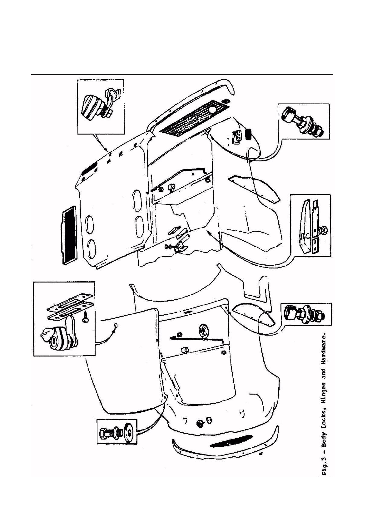
3 Body Locks, Hinges and Hardware 6
4 Basic Bonds and Joints 8
5 Box Section over Fracture 8
6 Body Repair Sections 10
7 Body Repair Sections 11
8 Bobbins 12
9 Method of Bonding in Bobbins 13
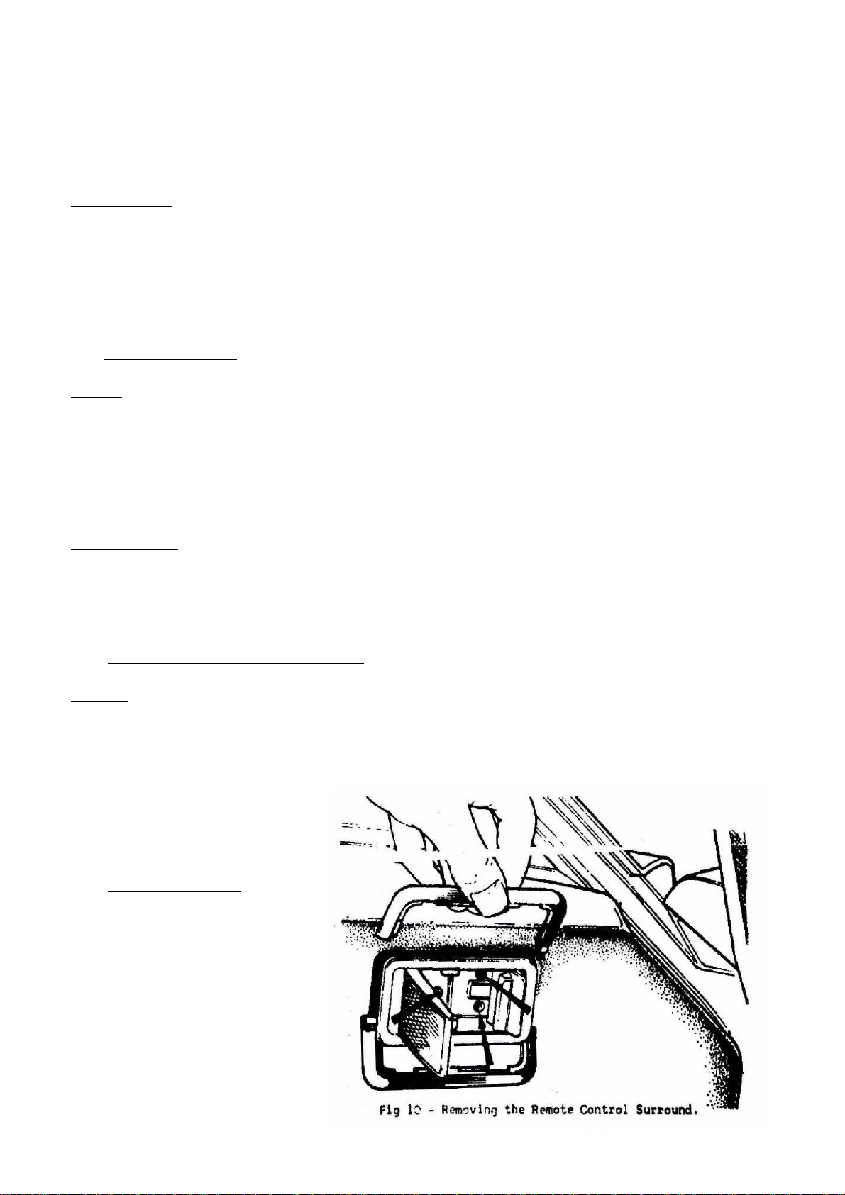
10 Removing the Remote Control Surround 16
11 Door Lock Mechanism (Series I) 18
12 Door Lock Mechanism (Series II) 19
13 Removing Door Window Motor 20
14 Doors and Window Mechanism 21
15 Removing the Door Hinge 24
16 Brightwork Strip Insertion Tool 25
17 Seat Adjustment 27
18 Application of glass cleaner/primer 35
19 Inserting narrow butyl strip in plastic trim 35
20 Location of windscreen support blocks 36
21 Main butyl strip in position 37
22 Location of interior finishing strip 38
23 Door hinge assembly 39

SECTION B – BODY PAGE 3
----------------------------------------------------------------------------------------Section Updated: 10/25/2007 10:55 AM at http://www.lotus-europa.com ----------------------------------------------------------------------------------------
B.1 - GENERAL DESCRIPTION.
The basis of the vehicle comprises a one piece moulded glass fibre reinforced plastic (G.F.R.P.)
body shell which straddles a steel backbone chassis and is attached to it at the points illustrated.
Whilst the chassis carries all the major structural loads, the body is used to carry or transfer the
remainder and when the body and chassis are correctly mounted, each contributes to the strength and
torsional stiffness of the other.
Construction of the body is generally in laminated 2.4 oz. (68.54 grams) chopped strand mat. A
high quality Polyester is used for the layup of all components giving a panel thickness of approx: .093 in.
(2.30 mm). In the more highly stressed areas, e.g., areas around side frames, metal inserts - especially
major structural attachment points, seat mountings, floor areas and wheel arch lips - the thickness is
increased up to .150 in. (3.80mm).
For replacement laminates or repairs any high quality commercial grade polyester can be used
although it should be a type having a reasonably high heat distortion point (see Service Parts List).
The body shell is laminated basically as an upper and lower moulding with an additional front
undertray chin piece which incorporates the extreme front chassis mounting points.
The nature of the design of all body panel joints is such that there are no critical or highly
stressed bonds or joints in the body shell itself and the major problem in creating all wheelarch and
bulkhead joints revolves around the need to obtain a perfectly waterproof or gasproof Joint as the case
may be.
-----------------------------------------------------------------------------------------------------------------------------------------------------------------------------------B.2 - MANUFACTIRING PROCESS.
General.
Construction of the body shell is achieved by the use of two main moulds. The upper mould
which contains the basic shape and the lower which contains the undertray and wheel arches, etc. These
two moulds are brought together in the process of the construction of the body unit forming in effect a
one piece moulding by lamination at the seams. The rear bulkhead is fireboard and is bonded into the
body shell.
The bonding or jointing of all panels and sections is in all cases provided by an adhesive or
glueing action, and for this reason the integrity [1] of the bond is dependent on the following factors.
Surface Preparation.
Polyester laminates (notably the "rough side") cure with a "greasy" surface usually caused by air
inhibition of the resin. This is best removed by light sanding of the greatest possible area and thereafter
swabbing off the dust with acetone. It is of no advantage to rough up with a toothed tool, leaving the
surface covered with fibre stubs as these will have no tensile strength at all and combined with loose
dust can actually act as a barrier between the bonding resin and the laminate.
When bonding to a moulded surface great care must be taken to remove all parting agents, e.g.,
wax or P.V.A. (Poly-vinyl-alcohol).
Bonding Mix.
Care has to be taken to see that the percentages of curing agents or hardeners are very carefully
calculated. If this is not done the bonding material may remain elastic or become too brittle, resulting in
an inferior bond.
Stressed Bonds.
Stressed bonds are invariably in the form of taped joints where one of the intersecting panels is
turned forming a reinforcement and successive

PAGE 4 SECTION B - BODY
----------------------------------------------------------------------------------------Section Updated: 10/25/2007 10:55 AM at http://www.lotus-europa.com ----------------------------------------------------------------------------------------

SECTION B – BODY PAGE 5
----------------------------------------------------------------------------------------Section Updated: 10/25/2007 10:55 AM at http://www.lotus-europa.com ----------------------------------------------------------------------------------------
PAGE 6 SECTION B - BODY
----------------------------------------------------------------------------------------Section Updated: 10/25/2007 10:55 AM at http://www.lotus-europa.com ----------------------------------------------------------------------------------------

SECTION B – BODY PAGE 7
----------------------------------------------------------------------------------------Section Updated: 10/25/2007 10:55 AM at http://www.lotus-europa.com ----------------------------------------------------------------------------------------
layers of woven tape are laminated into the angle where the two panels meet. It therefore follows that
these require more critical attention.
Wet Bonded Joints.
This system is employed on doors, boot lid and plenum chamber, the two or more joints being
clamped together while laminates are still wet.
------------------------------------------------------------------------------------------------------------------------------------------------------------------------------------
B.3 - ACCIDENT REPAIRS.
Assessing Accident Damage.
All damage must be classed as structural. However, inside this broad classification the damaged
area can be further defined as:
(a) High stressed.
(b) Moderate stressed.
(c) Low stressed.
And on that definition depends the original construction and therefore the repair method to be employed.
As a general rule there should be a bond wherever two panels touch, or wherever they close on
important points. It is usually possible to check these bonds both visually and physically for fractures or
breaks. Ascertain the cause of damage and the direction of impact and examine all panels or bonds
which may have been effected. A front end impact for example may possibly cause the bonds at the
bulkhead to split without the defect being normally visible and so on.
If necessary the metal on other components should be removed to facilitate examination as to the
extent of damage sustained.
Before the assessment can be completed it is essential to decide on the repair method to be
followed, the sizes of replacement panels to be ordered, etc. as the detailed instructions should be
carefully followed.
The extent of the damage (and size of replacement panels) should take into account surface
crazing.
Fire damage is the most difficult to assess but generally only the obviously burnt or charred
sections will need to be replaced or reinforced. The pedal mounting areas are heavily loaded and since
failure of these in service could be fatal, they should be carefully examined if they have been close to the
fire source.
Basic Bonds and Joints.
a. The old laminates should be tapered off for 3 to 4 in. (7.6 to 10.2 cm) on either side of the
fracture line, a reinforcing layup comprising alternative layers of chopped strand mat and fine
woven cloth is applied on both sides of the panel providing a symmetrical repair of great strength.
In most cases it is advisable to make the reinforcing layup on the reverse side of the panel
considerably stronger than that on the outside.
b. b. When it is difficult to taper both sides of the laminate an almost equally effective joint can be
obtained in which the reinforcing layer is done on the reverse side of the panel.
c. In this method the reinforcing layer is added on the reverse side, but with no tapering of the old
panels and with the crack of the old panel merely filled in, If this latter method is used it is
advisable to laminate a box or channel section over the joint at suitable intervals.
Repair Materials.
A full list of approved body process repair materials are contained in the Service Parts List (Part
No. 50T 3253.)

PAGE 8 SECTION B - BODY
----------------------------------------------------------------------------------------Section Updated: 10/25/2007 10:55 AM at http://www.lotus-europa.com ----------------------------------------------------------------------------------------
------------------------------------------------------------------------------------------------------------------------------------------------------------------------------------
B.4 - SUPERFICIAL DEFECT REPAIRS.
Pin Holes or Air Voids.
These are unfortunately quite inseparable from the hand layup system but since all body
components are "heated" to the maximum known service temperature of 180°F. (82°C.) in order to show
up any voids before painting they should never in theory give any difficulty. If they do then the only
solution is to dig them out and fill the holes with a polyester stopper or filler. The two commonly used
methods of filling these small holes are, (a) drilling or routing out so as to leave a larger hole with near
vertical walls, or (b) where the holes are enlarged by gouging or "picking out".
A common problem of repaired pin holes is the sinking of the paint surface some time after the
repair has been completed. This may result from the use of a cellulose paint stopper which has a higher
rate of shrinkage or in the case of a polyester stopper is usually caused by painting too soon after
effecting the repair, before the filler is properly cured. The filled areas should on no account be rubbed
down until the filler has fully cured, or sinking will obviously result.
Surface Crazing.
There are various causes of surface crazing, but practically all are caused by sharp impacts or accidental
damage. During an accident some panels may flex sufficiently to cause the surface to craze without
causing immediate apparent damage to the paint surface. The underside of wing areas are undersealed to
give more panel resilience, and should be re-undersealed if new wing sections have been fitted.
The crazing may not work its way through the paint surface for some weeks so that it is
necessary when assessing accident damage to carefully examine

SECTION B – BODY PAGE 9
----------------------------------------------------------------------------------------Section Updated: 10/25/2007 10:55 AM at http://www.lotus-europa.com ----------------------------------------------------------------------------------------
all panels, particularly near cracks or split bonds and in cases of doubt it may be possible to promote the
appearance of the crazing by applying gentle heat. Crazing itself generally stops at the first layer of glass
fibre and is consequently not in itself structurally serious, but the extensive crazing near damaged areas
should be taken as an indication of over stressing and the panel should be reinforced or replaced. It is not
possible to remedy crazing by simply re-surfacing with a further layer of resin.
Wrinkling or Distortion.
This phenomenon is usually caused by exposure to severe heat. This can cause the resin to soften
slightly and in doing so give way to any inbuilt or associated stresses. In all such cases technical advice
should be sought from Lotus Cars (Service) Ltd.
Split Bonds.
Small splits of bonds such as those around the door can occur, being caused mainly by excessive
flexing of the panels or by vibration and they should be arrested before they can extend and become
serious. The split should be peeled open slightly further, the inside flange surfaces should be roughened
up with a hacksaw blade and the appropriate type of bonding resin should be inserted before clamping
up. Clamping pressure should always be applied evenly, using a small slip of wood or metal if dimpling
of the panel surface is to be avoided. Where possible, all splits should be laminated from the inside.
Replacement Sections.
Where the repair of a damaged vehicle calls for replacement sections or panels it is
recommended that these be obtained direct from Lotus Cars (Service) Ltd.
Standard sectional repair moulds cater for the repair of damage in any area of the body unit.
These are so designed that they can be used individually or connected together for the manufacture of
the required section of the body. These are also used for locating new sections correctly relative to the
existing panels. These moulds are deliberately left unframed so as to accommodate slight discrepancies
and have been made on a standard painted body shell to allow for average paint thickness.
Repair sections available with their appropriate part numbers are shown in Figs. 6 and 7. Due to
the material used in construction of the body unit, cases of severe damage can often be economically
repaired, i.e. where damage has been severe enough to destroy virtually the whole front end of the
vehicle, as far as the bulkhead for instance, it is possible to graft on a new complete section.
Before cutting away the damaged parts or ordering replacement sections, the proposed method of
repair, positioning of joint lines, overlaps etc. should be ascertained (Section 'B.3').
Determine a method for the correct positioning of replacement sections and before cutting away
damaged parts check on any prominent features from which measurements can be made and scribe these
clearly on to the panels which are to be left intact.
Use masking tape or chalk to define the lines on which it is proposed to cut the panels and study
these lines thoroughly to see that (a) any damaged or slightly damaged panel which would be useful in
the aligning of another major panel will not be removed or, (b) on single skinned areas in particular the
proposed outline traverses longitudinal, lateral and horizontal definition points to assist easy lining up of
the new panel in all three places.
When repairs have been carried out in the vicinity of the front wheelarches, ensure the tyres do
not foul the front lower flange when the wheels are on full lock.
Underseal the wheelarch area to a depth of .125 in. (3mm) using "3M' material, or its equivalent
in consistency, to prevent gel-coat crazing caused by small stones etc. thrown up by the wheels.

PAGE 10 SECTION B - BODY
----------------------------------------------------------------------------------------Section Updated: 10/25/2007 10:55 AM at http://www.lotus-europa.com ----------------------------------------------------------------------------------------

SECTION B – BODY PAGE 11
----------------------------------------------------------------------------------------Section Updated: 10/25/2007 10:55 AM at http://www.lotus-europa.com ----------------------------------------------------------------------------------------

PAGE 12 SECTION B - BODY
----------------------------------------------------------------------------------------Section Updated: 10/25/2007 10:55 AM at http://www.lotus-europa.com ----------------------------------------------------------------------------------------
Positioning Replacement Panels.
a. Line up flat surface (e.g. undertray or floor area) using long wooden beams
bolted to undamaged area.
b. Line up main contours (e.g. wing sections) using splints and bolt into
position with flat or curved steel straps.
Metal Inserts.
The only metal inserts used are bobbins.
Bobbins.
Considerable use is made of die-cast metal
inserts, which are oval or square (door
hinge) in configuration and commonly
known as 'bobbins'.
These are designed to carry high loads
in most directions and also offer the
advantage of being accurately located
in the mountings.
Two basic forms are employed as follows:
Large (structural) bobbin - with 3/8 in.
or ½ in. holes (plain or threaded)
Small (semi-structural) bobbins - with
¼ in. or 5/16 in, holes (plain or
threaded).
The following advice is given on
dealing with bobbin failures.
Bobbins Pulling Out.
This could be caused by overloading, e.g., accident damage. Where the bobbin and its surrounding area
is accessible from the rough side of the laminates either naturally or by cutting non-weakening access
holes, the remedy is to improvise a local mould in plaster or glass fibre of the body surrounding the
finished side of the bobbin.
Difficulty may be experienced in temporary re-location of the bobbin and its surrounding laminate in its
original position. A local mould of the smooth side of the surrounding area (for example 6in. (15 cm.)
beyond in all directions) should eliminate this trouble. Re-registering can be achieved by drilling holes
through mould and body and through the bobbin before removing the repair mould.
Additional 4.00 in. (10.2 cm) square patches to make up to: ¼ in. and 5/16 in. bobbins: the equivalent of
5 x 1 ½ oz. layers.
3/8 in. and ½ in. bobbins: the equivalent of 7 x 1 ½ oz. layers.
Note: Number of patches to be determined from the above.
The bobbin can then be directly laminated on the old mounting by using the techniques described and
overlapping the new laminate on to the old by several inches whenever possible.
The larger bobbins are used only where the loadings are known to be high, e.g. body mountings, seat
attachments, etc. Smaller bobbins are used as location points or a blind attachment points.
Typical instances of non-structural applications are battery and spare wheel mounting points. In these
cases loose bobbins can be repaired by more localized and less exacting means, e.g., forcing in a dough
mixture around and behind the bobbin, winding tape around it, etc.

SECTION B – BODY PAGE 13
----------------------------------------------------------------------------------------Section Updated: 10/25/2007 10:55 AM at http://www.lotus-europa.com ----------------------------------------------------------------------------------------
Layup around Bobbins.
1. It is important that build-up around bobbins is as previously described as bobbins by nature of their
application are subjected to high loads, and will break out of the surrounding fibre glass if not bonded in
correctly.
2. Bobbins must be bolted to mould after "mould release agent" has been applied and prior to Gel-coat
application. Care must be taken to ensure that it sits well down on to the mould, and that the bobbin is
positioned correctly in accordance with the specification concerned.
Stripped Threads.
Whilst their oval section will prevent these bobbins from tuning in normal use they may loosen if too
much tightening pressure is applied, or when an attempt is made to tap them out to a large diameter. If a
thread is damaged or stripped an attempt should be made to drill the thread clear and use a bolt and lock
nut or drill oversize and fit a helicoil insert.
When fitting, an initial check should be made with
each bolt before tightening.
Only U.N.C. bobbins are employed and particular
care should be paid to fit only U.N.C. bolts to them.
Where the bolts are particularly tight this may be
due to resin within the threaded portion of the
bobbin, which can be remedied by tapping out.
Only the correct length of the bolt should be used,
i.e. those whose thread engages with the full depth
of the bobbin. No attempt should be made to pull
items up under heavy lead with a small engagement
of thread.
To avoid tightening up onto the plain shank of the
bolt it is recommended that only set screws be used,
i.e. those threaded all the way up to the head.
Laminating in a New Bobbin.
Firstly the laminates from the basic mounting
surface must overlap and interleave with the
laminates around the bobbins.
Secondly the laminate must be well built up under
the bobbin to prevent the bobbin from pulling out in a downward direction. This surrounding laminate
should in itself comprise a tight ring around the bobbin to prevent it from bursting out under diagonal
loads but if in doubt one or two layers of tape or cloth should be wound round the waist of the bobbin.
Finally plasticene or similar plugs should be used during laminating to keep the resin out of the bobbin
threads.
When properly laid the visible rough side wall will be nearly vertical in line with the bobbin top profile.
In effect a strong reinforcing ring of laminate surrounds the bobbin and this ring must be properly
connected to the basic laminate.

PAGE 14 SECTION B - BODY
----------------------------------------------------------------------------------------Section Updated: 10/25/2007 10:55 AM at http://www.lotus-europa.com ----------------------------------------------------------------------------------------
It is essential to keep the Gel-coat to a minimum thickness to prevent "crazing" and desirable that the
general layup thickness tapers gradually away from the bobbins.
Remember that tensile applications are the most demanding and require continuity of layup, that the
above instructions be strictly adhered to, that the safety of the vehicle may be dependent upon the
correctness of the application of these operations.
-----------------------------------------------------------------------------------------------------------------------------------------------------------------------------------B.5 - BODY CARE.
When washing the body, use plenty of cold water; never attempt to remove dust or mud from the
paintwork when dry, as this will damage the high gloss finish. Special preparations are marketed for
adding to the washing water; the use of these mild "detergents", as directed by the manufacturers will
expedite washing. Only use preparations of a reputable manufacturer. When dust and mud have been
removed with sponge and water, finally dry with a chamois leather.
If the car is kept clean by frequent washing, it will be found that polishing is almost unnecessary. If a
polish is used, do not allow it to contaminate the windscreen.
During the months of winter, many countries use salt to assist in the clearance of ice or snow.
Thoroughly wash the coachwork, the underside of the body and wings, and the chassis, either weekly or
more frequently depending on local conditions, to remove any salt deposit and prevent its corrosive
action.
The fibreglass coachwork will not of course be affected by any corrosive action but the metal parts
attached could be.
Bright Metal.
The attractive appearance of bright metal can be preserved if it is cleaned regularly. Each week wash
with a soap and water solution, rinse thoroughly with clean water and dry off. Staining or tarnish can be
removed with a good quality chromium cleaner.
Windscreen Cleaning.
The windscreen wipers are hinged so that they may be lifted clear of the glass, when cleaning the
windscreen. Never push the blades across the windscreen as this will damage the mechanism.
Upholstery and roof lining.
Normal cleaning consists of an occasional light wipe over with a cloth dampened in a mild soap and
water solution; it is important that the cloth is only damp not soaked.
Covers.
If it is desired to protect the vehicle with a portable cover, only use a lined and ventilated one. Unlined,
or unventilated covers could cause "sweating" of the paint finish.
Ensure body is dry before using the cover.
-----------------------------------------------------------------------------------------------------------------------------------------------------------------------------------B.6 - PAINT PROCEDURE.
The following information applies to Polyurethane Primer Surfacer and is the pull procedure when
starting with bare bodies.
Polyurethane Primer Surfacer was introduced into production as it gives more advantages through the
complete paint process than was previously possible.
A full list of painting materials is given in Section 'B' of the Service Parts List.

SECTION B – BODY PAGE 15
----------------------------------------------------------------------------------------Section Updated: 10/25/2007 10:55 AM at http://www.lotus-europa.com ----------------------------------------------------------------------------------------
To Paint.
1. Vacuum clean to remove all dust.
2. Solvent wipe and tack rag.
3. Spray one cross coat of polyurethane (part No.36B 6136) mixed 5 parts to 1 part catalyst (part No.
36B 6137). This may be thinned with up to 5% of thinner (part No.36B 6138) to give 45-55
seconds No.4 cup at 65 F (18.3°C).
4. Flash-off 5 minutes.
5. Spray one further coat of polyurethane mixed as above.
6. Flash-off 10 minutes.
7. Force dry 50 minutes at 130° - 140°F (54.4°-60°C). Then allow to cool.
8. Wet flat with "320" or "360" grade paper, using a copious supply of water to remove rubbing
sludge as this can seriously affect inter-coat adhesion if allowed to dry on the body surface.
9. Wash down thoroughly.
10. Dry off thoroughly. Areas rubbed through must be spot-primed with ivory sealer (Part No.46B
6153), thinned with thinner (Part No.36B 6143).
11. Solvent wipe and finally tack rag.
12. Spray door shuts and edges.
13. Apply 2 cross coats of colour keeping wet, using thinner (Part No.36B 6142) to give 23-24
seconds No.4 cup at 65°F (18.3°C) with 5 minutes flash between coats.
14. Flash-off 10 minutes
15. Force dry 50 minutes minimum at 130° - 140°F, (54.4° - 60°C). Allow to cool.
16. Wet flat with "400' grade paper and wash thoroughly.
17. Dry off thoroughly.
18. Solvent wipe and tack rag.
19. Spray door shuts and edges.
20. Apply 2 cross coats of colour keeping wet, using thinner (Part No=46B 6142) to give 23-24
seconds No.4 cup at 65°F (18.3°C} with 5 minutes flash between coats.
21. Flash-off 10 minutes.
22. Force dry 50 minutes minimum at 130° - 140°F. (54.4° - 60°C).
23. Inspect and rectify with "600" grade paper.
24. Polish with compound (coarse then fine).
25. Final polish with Pinchin & Johnson liquid wax polish (WWZ.14).
NOTE: - If a fast thinner is used in cold or humid conditions, or lack of adequate air movement or
heating exists in a spraying area, a commonly recognized defect known as "Blushing or Blooming" can
occur on finish colour, (a milky dulling of the paint appearing soon after application, whilst the film is
hardening). This is caused by the precipitation of atmospheric moisture due to the surface temperature of
a newly applied paint film being lowered by solvent evaporation.
When this "Blushing or Blooming" is seen on the colour coats, it is also probable that any surfacers
applied at that time and under those conditions will also be affected by this moisture precipitation. This
is not usually visible since surfacers normally dry to a matt finish, but blistering of the paint system or
faulty inter-coat adhesion may well occur later.
Painting Equipment.
The recommended spraying equipment using a Binks Bullows "230" Gun with colour is: -
Air nozzle 63.PB.
Air pressure 65-70 lbs.in. (4.57 - 4.92 kg.cm.)
Material nozzle 446.
Paint pressure 12-15 lbs.in. (.84 - 1.05 kg.cm.)
Needle valve 39.
PAGE 16 SECTION B - BODY
----------------------------------------------------------------------------------------Section Updated: 10/25/2007 10:55 AM at http://www.lotus-europa.com ----------------------------------------------------------------------------------------
Paint Removal.
Under no circumstances must "Paint Stripper" be used to remove paint from glass-fibre-reinforced
plastic (G.F.R.P.) bodies as this will attack the gel-coat, which MUST of course remain intact.
The recommended procedure for removing paint is: -
1. Wash off with a slow thinner, or
2. Wet flat with an appropriate grade of paper dependent on the amount of paint to be removed. Paper
heavier than "240" grade must not be used.
-----------------------------------------------------------------------------------------------------------------------------------------------------------------------------------B.7- BONNET (HOOD).
Bonnet.
To Remove:
Open the bonnet and remove the two bolts situated at the leading edge of the bonnet. Take note of any
spacing washers which may be found between the bonnet sides and the sides of the aperture.
To Replace:
Replacement is a reversal of the removal procedure.
Tool Roll Strap.
A strap is provided to secure the tool roll and vehicle jack. Correct stowage is with the foot of the jack
pushed down into the well of the spare road wheel with the upper part of the jack resting on the tyre wall.
The strap passes completely round the jack through the road wheel and is tightened securely.
It is possible that the vehicle jack if not stowed correctly can shift and jam the steering rack.
-----------------------------------------------------------------------------------------------------------------------------------------------------------------------------------B.8 - BOOT (TRUNK - ENGINE COVER).
Boot lid.
To Remove:
1. Open the boot to its full extent and remove the stay.
2. Release the nuts and washers securing the hinges to the lid and remove the lid. Do not misplace the
sealing gasket between the hinge and the boot lid.
To Replace:
1. Replacement is a reversal of the
removal procedure.
B.9 - DOOR TRIM PAD.
To Remove:
1. On doors with flush-fitting
remote control, loosen the three
securing screws and remove the
black plastic trim surround in
two halves. On doors with handle
type remote control release the
central screw retaining handle
and pull off the handle.

SECTION B – BODY PAGE 17
----------------------------------------------------------------------------------------Section Updated: 10/25/2007 10:55 AM at http://www.lotus-europa.com ----------------------------------------------------------------------------------------
2. Remove the two expanding fasteners from the glove pocket area of the door and ease the trim pad
away from the door working progressively round the edges of the pad, keeping as close to the clips
as possible. When all the clips are free, ease the pad from around the remote control handle.
3. Similarly, remove the central trim pad.
To Replace:
Replace the central trim panel.
1. Ease the remote control into its location, fit the trim pad clips into their corresponding snapsacs in
the door panel and replace the expanding fasteners.
2. Tighten the screws securing the flush-type remote control, or replace the handle in the case of Series
I vehicles.
-----------------------------------------------------------------------------------------------------------------------------------------------------------------------------------B.10 - DOOR LOCK REMOTE CONTROL.
Two types of lock remote control have been fitted in production, these being the lever type used on
Series I vehicles and a second, flush-fitting type on Series II vehicles.
To Remove (Lever Type).
1. Release the screw securing the handle.
2. Remove the trim pad (Section 'B.9').
3. Extract the split pin and remove washer and clevis pin securing remote control link to lock.
4. Release the two bolts with their nuts and washers securing the remote control mechanism to the door
and pull from its location.
To Remove (Flush Type).
1. Remove the three screws securing the remote control handle to the door. Remove the block plastic
trim surround in two halves (see Fig.10). Note that the handle cannot be released until after the trim
pad is free.
2. Remove the trim pad (Section 'B.9').
3. With the trim pad free, lift out the locking (small) flap locking rod from the handle mechanism and
the lock operating rod from the nylon block.
4. Remove remote control handle.
To Replace (both types).
1. Reverse the removal procedure.
-----------------------------------------------------------------------------------------------------------------------------------------------------------------------------------B.11 - DOOR LOCK.
Two types of lock have been fitted in Production, these being dependent on the type of lock remote
control used (Section 'B.10').
To Remove (first type).
1. Remove the trim pad (Section 'B.9').
2. From inside the door interior, release the remote control link at the lock.
3. From the door shut face, release the setscrews securing both the lock cover and the lock into the door.
To Remove (second type).
1. Remove the trim pad (Section 'B.9').
2. From inside the door interior, release the rods between the remote control locking flap to lock, nylon
block to lock, exterior door handle to lock and private lock to lock.
3. From the door shut face, release the setscrews securing the lock into the door.

PAGE 18 SECTION B - BODY
----------------------------------------------------------------------------------------Section Updated: 10/25/2007 10:55 AM at http://www.lotus-europa.com ----------------------------------------------------------------------------------------

SECTION B – BODY PAGE 19
----------------------------------------------------------------------------------------Section Updated: 10/25/2007 10:55 AM at http://www.lotus-europa.com ----------------------------------------------------------------------------------------

PAGE 20 SECTION B - BODY
----------------------------------------------------------------------------------------Section Updated: 10/25/2007 10:55 AM at http://www.lotus-europa.com ----------------------------------------------------------------------------------------
To Replace (both types).
1. Replacement is a reversal of the removal instructions, but ensure all lock mechanism with its
associated parts is fully operative (use a silicone-based grease) before replacing the trim pad.
-----------------------------------------------------------------------------------------------------------------------------------------------------------------------------------B.12 - LOCK STRIKER.
It is not necessary to disturb this component other than to fit a replacement or make adjustments. To
make adjustments, slacken the retaining screws in the striker, adjust as necessary and tighten the screws.
If the securing screws are inadvertently released, the screws tapping plate, which is BEHIND the door
shut face will be displaced from its location.
To obtain access it will be necessary to remove the dust shield in the wheelarch (Section (B.32').
-----------------------------------------------------------------------------------------------------------------------------------------------------------------------------------B.13 - DOOR W INDOW MOTOR.
To Remove:
1. Remove the door
trim pad (Section
‘B.9').
2. Set the window so
that the operating
arm is horizontal.
3. Disconnect the
battery (see Section
‘M.2’).
4. Disconnect the
motor cables from
their 'Lucar'
terminals.
5. Remove the set
screws securing the
motor assembly to
the inner door panel
(see Fig. 13), then
slide the operating
arm from the
window steady plate.
Lower the motor to
the inner bottom of the door. Support the window with a suitable block of wood to avoid the
possibility of the window becoming displaced from its channels, as could happen if allowed to rest
on the inner bottom of the door.
6. Turn the motor assembly through 90° and lift out though the large aperture at the forward end of the
inner door panel.
To Replace
Replacing the window motor is a direct reversal of the removal procedure.
 Loading...