

Page 1

Page 1
Lotus Service Notes Introduction
CONTENTS
ELISE & EXIGE; 2004 M.Y. ONWARDS; WITH 1ZZ/2ZZ ENGINE
Section
Technical Data - Engine TDP
- Vehicle TDQ
Chassis AH
Bodycare & Repair BQ
Body Fittings BR
Front Suspension CI
Rear Suspension DH
Engine & Engine Management - Lotus supplement EH
- Toyota 1ZZ/2ZZ engine repair manual *
* see separate manual B120T0327J
- Toyota 2ZZ-GE engine supplement #
# see separate manual C120T0327J
Engine Management EMP
Transmission - Lotus supplement FJ
- Toyota C64 transmission repair manual ~
~ see separate manual D120T0327J
- Toyota C56 transmission repair manual ^
^ see separate manual TBA
Wheels & Tyres GH
Steering HG
Brakes JJ
Engine Cooling KH
Fuel System - Except North America LJ
- North America LK
Electrics MP
Maintenance & Lubrication OI
Air Conditioning, Heating & Ventilation PL
Clutch QH
Passive Restraint (North America) WD
Supplement - Exige Supercharged (S/C) Exige S/C
Supplement - 2-Eleven 2-Eleven
Page 2

Page 2
Lotus Service Notes Introduction
VEHICLE IDENTIFICATION NUMBER & ENGINE NUMBER
The Vehicle Identification Number (V.I.N.) is stamped on the chassis in the right hand front wheelarch
area, viewable with the front wheels turned to right full lock, and is also printed on a label stuck to the inside
of the chassis sideframe alongside the driver's seat. The engine number is marked on a vertical patch at the
right hand side of the rear face of the cylinder block, adjacent to the clutch housing.
Both numbers should always be quoted with any vehicle enquiries, as Factory records are filed against
V.I.N., and specification change points are identified by V.I.N. or engine number. The vehicle licence number
should be considered irrelevant, since it may not accurately reflect vehicle age, and may also be changed during the car’s life.
The V.I.N. comprises 17 characters, coded in accordance with European Economic Community (EEC)
and National Highway Traffic Safety Association (NHTSA) directives. For change point identification in Service
Notes, Service Bulletins and Service Parts Lists, typically, only characters 10 (model year), and 14 to 17 (serial
number) will be quoted.
'2004 M.Y. onwards
V.I.N. ON
CHASSIS
ohs119a
V.I.N. LABEL
ohs104 ENGINE NUMBER ohs133
Assembly
Plant Model
Vehicle Type H = Hethel 2 = 2-Eleven
Manufacturer 111 = Elise Check B = Shah 3 = Elise
Identifier Code 123 = 2-Eleven Digit Alam 8 = Exige
S C C
1 2 3 4 5 6 7 8 9 10 11 12 13 14 15 16 17
Engine Type Restraint Model Year Chassis/Body Serial
L = Motorsport A = Active belts 4 = 2004 A = LHD Fed.
Number
N = 2ZZ s/c 255 C = Dual S.I.R. 5 = 2005 C = RHD
P = 2ZZ n.a. + active belts 6 = 2006 D = LHD
V = 2ZZ s/c 7 = 2007 F = U.K. SVA RHD
Y = 1ZZ 8 = 2008 G = U.K. SVA LHD
9 = 2009 H = Motorsport*
A = 2010 J = Motorsport*
L = LHD Fed. a.c.
* Track only. Not M = LHD Can. a.c.
approved for road use N = RHD a.c.
P = LHD a.c.
Page 3

Page 3
Lotus Service Notes Introduction
MODEL HISTORY MILESTONES
Elise 111R Introduction: January 2004
VIN character 4 = P; Character 13 = 3; Serial number from 0970
Note that the serial number sequence is shared with other Elise variants.
Changes from previous model include: Toyota powertrain with 1.8 litre VVTL-i engine and 6-speed transmission. Twin exhaust tailpipes exiting through centre of diffuser. Larger fuel tank with new pump. Revised
chassis rail rear ends, new rear subframe, revised seat belt mounting frame backstays. Revised rear suspension wishbones, springs and dampers. ABS brake control with vacuum servo. Revised front bonnet grilles
and access covers.
2004 Exige Introduction: March 2004
VIN character 4 = P; Character 13 = 8; Serial number from 1092
Note that the serial number sequence is shared with other Elise variants.
Differences compared with Elise 111R include: Restyled front and rear clamshells with roof scoop, new
tailgate panel and strut mounted rear aerofoil. Front body splitter panel. Re-styled road wheels, wider on the
front, and Yokohama A048 tyres.
2005 M.Y. Elise for North America: May 2004
VIN character 10 = 5; Character 12 = L; Serial number from 0001
Note that the serial number sequence is shared with other Elise variants when '05 M.Y. is adopted for
those models later in the year.
Differences compared with Elise 111R include: Driver and passenger airbags, pyrotechnic seat belt pretensioners; Re-styled fascia and dashboard structure; Front speakers moved onto top surface of fascia, stowage pockets incorporated into dashboard end panels, fixed windscreen demist vents. Engine start button in
driver's side switch panel. Revised springs and dampers, Yokohama AD07 tyres. Side marker lamps on front
and rear wheelarch lips. Revised fuel system with fuel filler flap.
Lotus Sport Exige 240R: March 2005
Limited edition of 50 units produced as post registration official factory conversions of '05 Exige by the
Lotus Sport workshops at Hethel, for U.K. and certain overseas territories. The car is not identifiable from the
VIN coding.
Differences compared to standard Exige include: 243 bhp engine upgrade using Eaton M62 supercharger
with integral by-pass valve, air/air chargecooler and 5th fuel injector. Re-programmed ECU. Accusump.
Stiffened springs & Ohlins adjustable dampers. Adjustable front anti-roll bar. Chassis rear brace kit. Forged
5-spoke widened roadwheels & Yokohama A048 tyres. Motorsport brake pads, braided hoses, yellow callipers,
Castrol SRF brake fluid. Sport Yellow body colour with black wheels, or Sport Black body with silver wheels.
Black interior with yellow inserts. 4-point harnesses, T45 roof hoop and backstays.
2006 M.Y. Introduction: September 2005
VIN character 10 = 6; Serial number restarts at 0001, common to all variants.
Introduction of USA Exige and Canadian Elise.
5-speed Elise remains unchanged.
Differences between 6-speed '06 Elise and '05 include; Electronic throttle control (using no mechanical
cable). Optional Lotus Traction Control (LTC) or Limited Slip Differential (LSD) with LTC. Standard fit Yokohama
AD07 tyres on non-USA cars. Optional forged wheels with new 6.0 in front size. LED rear lamp clusters incorporating reflectors (formerly separate), and commonised USA type CHMSL. ProBax seat foams. New body
colours. USA & Canadian Elise; revised fuel tank and evap. loss system. Canadian Elise uses daytime running
lights and clutch down start allow switch. USA Exige similar to non-USA, but with USA airbag interior.
Sports Racer: October 2005
Special paint versions of '06 M.Y. 111R in either Ardent Red with triple Monaco White stripes, or Nightfall
Blue with twin Monaco White stripes. Combined total of 199 units with unique build plate on sill. Forged wheels
(6J on front), AD07 tyres, sport suspension, twin front oil coolers, LTC. Black leather interior with red or blue
stitching, and red or blue 'Elise' embroidered into head restraints. Sports Racer decals.
Page 4

Page 4
Lotus Service Notes Introduction
Exige Cup 190 & 240: January 2006
Limited number of competition oriented naturally aspirated (190) or supercharged (240) models produced
as post registration official factory conversions of '06 Exige by the Lotus Sport workshops at Hethel for U.K.
and certain overseas territories. Not identifiable from VIN coding.
Differences compared to 240R (see above) include: Electronic throttle, high flow port injectors (no 5th).
Cup 240 fitted with torque sensing LSD with LTC. Cup 190 uses friction plate LSD. Standard Exige wheels in
'Hi-power' silver. Race cars fitted with FIA 6-point roll cage, remote kill switch, extinguisher system. Standard
body colours.
Exige S: February 2006
VIN character 4 = V
Factory built type approved supercharged Exige. Not USA.
Differences to standard Exige include: 221 PS supercharged engine similar to 240R but using electronic
throttle, smooth flow inlet adaptor, standard injectors without 5th injector, modified downpipe, optimised muffler
with single oval tailpipe. Enlarged roof duct inlet for chargecooler. Body colour splitter, scoops and aerofoil.
'Exige S' decal on rear transom, 'S' on front quarter panels.
USA Lotus Sport Elise: March 2006
Limited edition of 50. Saffron Yellow with twin Storm Titanium stripes. Saffron Yellow centre console. Yel
low highlighted sports seats, 'carbon' door trim inserts. Harness bar, T45 seat belt mounting frame. Motorsport
mats, stalks, winders and parking brake sleeve. Traction control, supersport suspension, black forged wheels,
Yokohama A048s, braided brake hoses, silicone fluid, motorsport clutch. Lotus Sport decals and Union flags.
Lotus Sport chassis plate.
2007 M.Y. & Elise S Introduction: June 2006
VIN character 10 = 7; Serial number restarts at 0001, common to all variants.
VIN character 4 identifies engine type. Elise S = Y
Differences between '07 Elise/Exige and '06 include: Elise 111R renamed Elise R; New sealed headlamp
units; raised LOTUS lettering on rear transom; additional screen pillar seal; Alpine audio; improved HVAC ducting. New model Elise S uses 1ZZ-FE engine producing 100 kW, with variable inlet timing but fixed valve lift,
plastic inlet manifold, revised intake snorkel, revised exhaust manifold and downpipe, smaller tailpipes within
standard trims. Elise S also uses new C56 5-speed transmission and 6-spoke roadwheels sharing styling of
standard '01 model wheels.
USA Exige S: October 2006
The specification of the USA Exige S is that of the standard USA Exige and option packs, apart from the
engine, which is as non-USA Exige S with the following exceptions: High flow port injectors, specific engine
programming, 223 PS, 223 Nm. Carry-over features from the non-USA Exige S include exhaust downpipe and
optimised muffler with single oval tailpipe, roof air intake funnel mouth.
Exige S British GT Special Edition: November 2006
Celebrating Lotus Sport Cadena’s 2006 British GT3 Team Championship victory.
Differences to standard Exige S include: Torsen LSD & Lotus Traction Control. Chassis rear brace kit.
T45 roof hoop & stays. Braided brake hoses. Level 1 sports exhaust. Forged 7-bifurcated spoke silver wheels.
Lotus Sport black metallic body colour with Sport yellow & Arctic silver quad stripes, supplier decals on sills,
Lotus Sport visor strip, Cadena decals on front wings, GT3 decal on rear clam, GT3 winners decal with unique
build number on rear quarter panel, Lotus Sport build plate with build number. 4-point harnesses, black/yellow
door trims and unique black/yellow trimmed seats. Optional a.c. Optional GT pack available as post registration
official factory conversion by Lotus Sport workshops at Hethel for U.K. and certain overseas territories, includes:
High flow injectors, different ECU & unique calibration for 243 bhp, Accusump, 2-way adjustable Ohlins dampers
with uprated springs, 308mm front discs & 4-piston A.P. callipers, Pagid pads, Castrol SRF brake fluid.
Page 5

Page 5
Lotus Service Notes Introduction
USA Low Speed Damage Mitigation: January 2007
From ‘07 USA VIN serial no. 1579.
To meet USA safety legislation, modifications made to Elise/Exige: Front; armatures and foam inserts
added between crash structure and clamshell. Rear; bumper panel housing foam pads either side of licence
plate, narrower rear grilles, reinforced boot floor and diffuser support panel, stiffened diffuser. Some elements
commonised for all markets.
Lotus Sport Exige Cup 255: January 2007
Produced as post registration official factory conversions of '07 Exige S by the Lotus Sport workshops at
Hethel for certain territories, excluding U.K. and USA. Not identifiable from VIN coding.
Based on Exige Cup 240 (see above) with following differences: Power increase to 255 PS by; unique
ECU calibration, enlarged chargecooler, extended roof duct, larger air cleaner and intake spout, uprated fuel
pump. A.P. Racing 4 piston alloy front callipers, 308mm front discs.
2-Eleven Introduction: May 2007
VIN character 6/7/8 = 123; Character 13 = 2
Extreme, minimalist, track focussed Elise variant based on Exige Cup 255 powertrain componentry, but
using new chargecooler arrangement. Produced in small numbers for U.K. and certain overseas territories. In
U.K. only, SVA road going version available. All other territories only for track use, in LHD or RHD.
New body with no doors or roof. Aeroscreen. Rear aerofoil in two versions. FIA compliant roll over bar.
Chassis rear brace, unique front top wishbones and steering arms, optional Ohlins suspension. Accusump,
twin front oil coolers. Standard LTC, optional variable LTC & Launch Control. Uprated clutch. Odyssey battery.
Limited warranty for SVA cars. Extensive options list.
USA Elise Limited Edition 'Type 72D'
Limited edition of 50 cars to commemorate the 35th anniversary of Lotus' F1 1972 World Championship
victory with the type 72D.
Phantom black body colour with hand painted gold pinstriping. Rear body spoiler, black diffuser. Gold
laurel leaf decal on front quarters, gold 'Elise' and 'Type 72D' decals, gold raised LOTUS lettering, gold/black
nosebadge, gold fuel filler cap. Gold Exige 8 split-spoke wheels with Yokohama A048 tyres and sports suspension. Black & gold seats and interior trim details with Limited Edition plaque. Scale model crash helmet.
Page 6

Page 6
Lotus Service Notes Introduction
ENGINE BAY UNDERTRAY/DIFFUSER
For certain service operations, it may by necessary to remove the engine bay undertray and/or diffuser
panel. The panels contribute to the aerodynamic performance of the car, and also help to keep the engine bay
clean. Do not run the car without the panels fitted.
3 screws to licence 1 screw each side
plate plinth to grille panel
b275b
Diffuser panel
3 screws
each side
Single screw each to tank bay
side to clamshell panel
Undertray
front edge
M8 button head slots into
(2) to subframe 5 screws M8 button head chassis
undertray (2) to lower
to diffuser link brackets
Page 7
Page 7
Lotus Service Notes Introduction
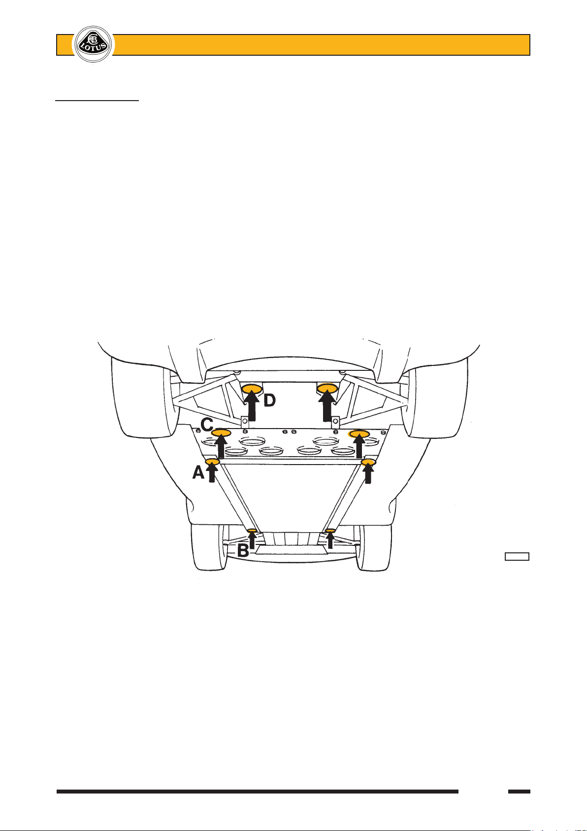
JACKING POINTS
Care must be taken when using a lifting jack or hoist to position the device only in one of the the areas
shown in the illustration, with a suitable rubber or timber pad protecting the chassis from surface damage. If a
4-point lift is to be used, the engine bay undertray/diffuser panel (if fitted) must first be removed. When using
a 4-point lift, it is strongly recommended that for optimum stability and safety, positions B and D are used.
A; Identified by a blue sticker. Beneath crossmember ahead of fuel tank bay. To be used one side at a time
for wheel changing - lifts both wheels on one side. Do not use with a four point garage lift.
B; Beneath the front end of the right or left hand main chassis rail, behind the front wheelarch. Garage use
with 4-point lift in conjunction with (C).
C; The engine undertray/diffuser panel must first be removed. Beneath the outboard end of the chassis
crossmember ahead of the rear wheelarches. Take care to position the jack between the fixing screws
for the fuel tank bay perforated undershield. Garage use with 4-point lift in conjuction with (B).
D; The engine undertray/diffuser panel must first be removed. Beneath the rear subframe, close to the lower
wishbone rearmost mountings.
Jacking at any other point may damage the chassis or body structure and/or jeopardise safety.
ohs49sn
Page 8

Page 1
Lotus Service Notes Section TDP
TECHNICAL DATA - ENGINE
SECTION TDP
Page
General .................................................................................................................... 2
Cylinder Block .......................................................................................................... 2
Cylinder Head .......................................................................................................... 3
Valves & Springs ...................................................................................................... 3
Camshafts ................................................................................................................ 3
Pistons ..................................................................................................................... 3
Connecting Rods ...................................................................................................... 3
Crankshaft ............................................................................................................... 3
Oil Pump .................................................................................................................. 3
Coolant Thermostat .................................................................................................. 3
sn_tdp_engine_cyclone.indd 1 03/07/2006 14:59:41
Page 9

Page 2
Lotus Service Notes Section TDP
GENERAL
Type designation - All except Elise S 2ZZ-GE
- Elise S 1ZZ-FE
Configuration & no. of cylinders in-line 4 Capacity 1796 cm3 1794 cm³
Bore 82.00 mm 79.00 mm
Stroke 85.00 mm 91.50 mm
Camshafts Chain driven DOHC Valves 4VPC in pentroof chambers
Valve control - inlet Variable timing & lift Variable timing
- exhaust Variable lift Valve timing - inlet - low & medium speed - open 33° BTDC to all speeds 48° BTDC
to 10° ATDC to 5° BTDC
- close 15° ATDC to all speeds 12° ATDC
58° ATDC to 55° ATDC
- high speed - open 58° BTDC to
15° BTDC
- close 54° ABDC to
97° ABDC
- exhaust - low & medium speed - open 14° BBDC all speeds 42° BBDC
- close 34° ATDC all speeds 2° ATDC
- high speed - open 36° BBDC
- close 60° ATDC
Compression ratio 11.5:1 10.0:1
Compression pressure (250 rpm) - new 1400 kPa (203 psi) 1500 kPa (218 psi)
- service limit 1000 kPa (145 psi) Firing order 1,3,4,2 Spark plugs NGK IFR6A11 NGK BKR5EYA-11
Spark plug gap 1.1 mm 1.0 ± 0.05 mm
Maximum continuous engine speed 8000 rpm 6,800 rpm
Maximum transient engine speed 8500 rpm 7,000 rpm
Idle speed 850 rpm Ignition system Direct ignition using individual H.T. coils
for each cylinder
Fuel system Fully sequential indirect fuel injection,
Lotus T4 controller
Fuel requirement (minimum) Unleaded 95 RON Peak power (1999/99/EC) 141 kW (192 PS) 100 kW (136 PS)
@ 7,800 rpm @ 6,200 rpm
Peak torque (1999/99/EC) 181 Nm 172 Nm
@ 6,800 rpm @ 4,200 rpm
Exhaust emissions - CO 0.42 g/km 0.23 g/km
- HC 0.078 g/km 0.050 g/km
- NOx 0.0121 g/km 0.0217 g/km
- HC + NOx 0.0792 g/km 0.0717 g/km
- CO2 208 g/km 196 g/km
CYLINDER BLOCK
Material Aluminium alloy, Aluminium alloy,
MMC cylinder bores cast iron liners
Deck face flatness tolerance 0.05 mm Cylinder bore diameter 82.000 - 82.013 mm 79.000 - 79.013 mm
sn_tdp_engine_cyclone.indd 2 03/07/2006 14:59:41
Page 10

Page 3
Lotus Service Notes Section TDP
CYLINDER HEAD 2ZZ-GE 1ZZ-FE
Material Aluminium alloy Head face flatness tolerance 0.05 mm Reface limit No machining -
VALVES & SPRINGS
Valve seat angle in head 45° Valve face angle 44.5° Cold valve clearance (between cam & follower) - inlet 0.10 - 0.16 mm 0.15 - 0.25 mm
- exhaust 0.24 - 0.30 mm 0.25 - 0.35 mm
Valve guide standout 15.3 - 15.7 mm 8.7 - 9.1 mm
Valve spring free length - inlet 46.4 mm 45.9 mm
- exhaust 46.5 mm 45.9 mm
CAMSHAFTS
End float - new 0.04 - 0.14 mm 0.04 - 0.10 mm
- service limit 0.15 mm 0.11 mm
PISTONS
Diameter - @ 90° to pin, 12 mm from bottom edge 81.975 - 81.993 mm
- @ 90° to pin, 25 mm from top edge 78.925 - 78.935 mm
Ring gap, 110 mm from block top face - std. - no.1 0.25 - 0.35 mm -
- no.2 0.35 - 0.50 mm -
- oil rail 0.15 - 0.40 mm -
- max. - no.1 1.1 mm -
- no.2 1.2 mm -
- oil rail 1.1 mm Ring groove clearance 0.030 - 0.070 mm -
CONNECTING ROD
Small end bush inside diameter 20.011 - 20.023 mm 20.012 - 20.021 mm
Big end side clearance 0.16 - 0.34 mm -
CRANKSHAFT
Crankshaft endfloat - new 0.04 - 0.24 mm -
- service limit 0.30 mm Main journal diameter 47.988 - 48.000 mm Crankpin diameter 44.992 - 45.000 mm 43.992 - 44.000 mm
Max. taper & out of round, journals & crankpins 0.02 mm -
OIL PUMP
Oil pressure - idle, running temperature 39 kPa (6 psi) min. 29 kPa (4 psi) min.
- 3,000 rpm, running temperature 300 - 540 kPa (45 - 80 psi)
Outer rotor to housing clearance - new 0.13 - 0.18 mm -
- service limit 0.33 mm Inner rotor tip clearance - new 0.06 - 0.18 mm -
- service limit 0.33 mm Rotor end float - new 0.03 - 0.08 mm -
- service limit 0.16 mm -
COOLANT THERMOSTAT
Valve opening temperature 80 - 84°C Valve lift at 90°C 10 mm Header tank pressure cap 108 kPa Cap opening pressure 93 - 123 kPa -
sn_tdp_engine_cyclone.indd 3 03/07/2006 14:59:41
Page 11

Page 4
Lotus Service Notes Section TDP
sn_tdp_engine_cyclone.indd 4 03/07/2006 14:59:41
Page 12

Page 5
Lotus Service Notes Section TDP
sn_tdp_engine_cyclone.indd 5 03/07/2006 14:59:41
Page 13

Lotus Service Notes Section TDQ
TECHNICAL DATA - VEHICLE
SECTION TDQ
Page
Dimensions ........................................................................................................ 2
Capacities .......................................................................................................... 2
Wheels & Tyres ................................................................................................... 3
Front Suspension ................................................................................................. 3
Rear Suspension ................................................................................................. 4
Electrical ............................................................................................................. 5
Transmission ....................................................................................................... 5
Clutch .................................................................................................................. 6
Brakes ................................................................................................................. 6
Steering ............................................................................................................... 6
Fuel Consumption ............................................................................................... 6
Page 1
Page 14

Lotus Service Notes Section TDQ
DIMENSIONS
Overall length - Elise 3785 mm
- Exige 3797 mm
Overall width - exc. mirrors - Elise 1719 mm
- Exige 1727 mm
- inc. mirrors 1850 mm (approx.)
Overall height (at kerb weight) - Elise 1117 mm
- Exige 1159 mm
Wheelbase 2300 mm
Track - front 1457 mm
- rear 1507 mm
Ground clearance (mid-laden) - except std. USA 130 mm
- std. USA 135 mm
Front overhang - Elise 783 mm
- Exige 805 mm
Rear overhang - Elise 702 mm
- Exige 692 mm
Approach angle (at kerb) 13.5°
Departure angle (at kerb) 23°
Unladen weight - 111R/Elise R - total 860 kg >
(lightest) - front 327 kg > incl. full fuel tank
- rear 533 kg >
- Elise S - total 862 kg }
(lightest) - front 328 kg } incl. full fuel tank
- rear 534 kg }
- USA Elise - total 912 kg )
(heaviest) - front 344 kg ) incl. full fuel tank
- rear 568 kg )
- non-USA Exige - total 875 kg >
- front 328 kg > incl. full fuel tank
- rear 547 kg >
- non-USA Exige S- total 935 kg }
- front 355 kg } incl. full fuel tank
- rear 580 kg }
- USA Exige - total 920 kg )
- front 350 kg ) incl. full fuel tank
- rear 570 kg )
Max. weight - 111R/R, Exige - total 1166 kg >
- front 443 kg > incl. occupants & luggage
- rear 723 kg >
- Elise S - total 1126 kg }
- front 428 kg } incl. occupants & luggage
- rear 698 kg }
- USA Elise - total 1162 kg )
- front 441 kg ) incl. occupants & luggage
- rear 721 kg )
- non-USA Exige S- total 1199 kg >
- front 456 kg > incl. occupants & luggage
- rear 743 kg >
Trailer towing Not permissible
CAPACITIES
Engine oil - refill inc. filter 4.4 litre
(+ 3.5 litre if front mounted oil coolers are drained)
High/low dipstick mark difference 1.5 litre
Transmission oil 2.3 litre
Fuel tank 43.5 litre
Page 2
Page 15

Lotus Service Notes Section TDQ
Coolant 12 litre
Refrigerant 550 g
Rear luggage compartment 50 kg/112 litre
WHEELS & TYRES
Tyres
Type - Elise std. - prior '06 Bridgestone Potenza RE040
- from '06 Yokohama Advan Neova AD07
- USA Elise Yokohama Advan Neova AD07
- Elise option, Exige Yokohama A048
Size - front - Elise std. 175/55 R16 80W
- USA Elise 175/55 R16 80W
- Elise option, Exige 195/50 R16 84W
- rear - Elise std. - RE040 225/45 R17 90W
- AD07 225/45 R17 91W
- USA Elise - AD07 225/45 R17 91W
- Elise option, Exige - A048 225/45 R17 90W
Pressure (cold) - front 1.8 bar (26 lb/in²)
- rear 2.0 bar (29 lb/in²)
Winter Tyres
Type - front Pirelli 210 Snowsport
- rear Pirelli 240 Snowsport
Size - front 195/50 R16
- rear 215/45 R17
Pressure (cold) - front 1.8 bar (26 lb/in²)
- rear 1.9 bar (27.5 lb/in²)
Tyre studding Not permitted
Tyre chains Pewag Neon X3-NX373
fitted only on rear winter tyres
Wheels
Type - Elise 111R/R/USA Cast alloy, 8 spoke
- Elise S Cast alloy, 6 spoke
- Exige std. Cast alloy, 8 Y-spoke
- Elise/Exige option Forged alloy, 7 split-spoke
Size - front - Elise std. 5.5J x 16
- Elise option 6.0J x 16 (forged + AD07)
- Elise option, Exige 6.5J x 16 (forged + A048)
- rear 7.5J x 17
Wheel bolt torque 105 Nm (77 lbf.ft)
FRONT SUSPENSION
Type Independent. Upper and lower wishbone; co-axial
coil spring/telescopic damper unit; anti-roll bar
Steering axis inclination 12 ° nominal
Geometry specification - Standard Elise:
Mid-laden ride height (reference height for geometry check)
- USA Elise from VIN 3013 & 111R/R/S - front 130 mm below front end of chassis siderail
- rear 130 mm below rear end of chassis siderail
- USA Elise prior VIN 3013 - front 135 mm below front end of chassis siderail
- rear 135 mm below rear end of chassis siderail
Castor - optimum + 3.8°
- tolerance range + 3.5° to + 4.1°; max. side/side 0.35°
Page 3
Page 16

Lotus Service Notes Section TDQ
Camber - optimum - 0.1°
- tolerance range + 0.1° to - 0.3°; max. side/side 0.2°
Alignment - optimum Zero
- tolerance range 0.5 mm toe out, to 0.7mm toe-in overall
Geometry specification - Sportpack Elise, Exige:
Mid-laden ride height (reference height for geometry check)
- front 130 mm below front end of chassis siderail
- rear 130 mm below rear end of chassis siderail
Castor - optimum + 3.8°
- tolerance range + 3.5° to + 4.1°; max. side/side 0.35°
Camber - optimum - 0.3°
- tolerance range - 0.1° to - 0.5°; max. side/side 0.2°
Alignment - optimum Zero
- tolerance range 0.5 mm toe out, to 0.5 mm toe-in overall
Geometry specification - Supersportpack Elise, Exige:
Mid-laden ride height (reference height for geometry check)
- front 120 mm below front end of chassis siderail
- rear 120 mm below rear end of chassis siderail
Castor - optimum + 3.8°
- tolerance range + 3.5° to + 4.1°; max. side/side 0.35°
Camber - optimum - 0.2°
- tolerance range + 0.1° to - 0.3°; max. side/side 0.2°
Alignment - optimum Zero
- tolerance range 0.5 mm toe out, to 0.7 mm toe-in overall
REAR SUSPENSION
Type Independent. Upper and lower wishbone; co-axial
coil spring/telescopic damper.
Geometry specification - Standard Elise:
Mid-laden ride height (reference height for geometry check)
- USA Elise from VIN 3013 & 111R/R/S - front 130 mm below front end of chassis siderail
- rear 130 mm below rear end of chassis siderail
- USA Elise prior VIN 3013 - front 135 mm below front end of chassis siderail
- rear 135 mm below rear end of chassis siderail
Camber - optimum - 1.8°
- tolerance range - 1.6° to - 2.0°; max.side/side 0.2°
Alignment - optimum 1.2 mm toe-in each side
- tolerance range 1.2 to 1.8mm toe-in each side
max.side/side 0.3 mm
Geometry specification - Sportpack Elise, Exige:
Mid-laden ride height (reference height for geometry check)
- front 130 mm below front end of chassis siderail
- rear 130 mm below rear end of chassis siderail
Camber - optimum - 1.8°
- tolerance range - 1.6° to - 2.0°; max.side/side 0.2°
Alignment - optimum 1.5 mm toe-in each side
- tolerance range 1.2 to 1.8 mm toe-in each side
max.side/side 0.3 mm
Geometry specification - Supersportpack Elise, Exige:
Mid-laden ride height (reference height for geometry check)
- front 120 mm below front end of chassis siderail
- rear 120 mm below rear end of chassis siderail
Page 4
Page 17

Lotus Service Notes Section TDQ
Camber - optimum - 2.5°
- tolerance range - 2.0° to - 2.7°; max.side/side 0.2°
Alignment - optimum 1.8 mm toe-in each side
- tolerance range 1.5 to 2.0 mm toe-in each side
max.side/side 0.3 mm
ELECTRICAL
Light Bulbs Wattage Type
Headlamps - prior '07 - main beam 55 H7
- dip beam 55 H1
- from '07 - main beam 55 H7U
- dip beam 55 H7U
Driving lamps 55 H3
Front side/parking lamps 5 W5W
Side repeater lamps 5 WY5W amber
Front turn indicators 21 PY21w amber
Rear turn indicators - prior '06 21 H21 )
Stop/Tail lamps - prior '06 4/21 P21/4w )
Stop lamps (USA) - prior '06 21 H21 ) '06 onwards use
Tail lamps - prior '06 5 R5W ) LED clusters
Tail/turn lamps (USA) - prior '06 4/21 P21/4w )
Fog/Tail lamps - prior '06 4/21 P21/4w
Reversing lamp - prior '06 21 H21
Turn lamps (non-USA) - from '06 16 W16W
Reverse lamps - from '06 16 W16W
High mounted stop lamp 2.5 16 x LED
Licence plate lamps 5 C5W
Interior lamp 5 W5 W
System voltage/polarity 12V negative earth
Alternator 85A
Battery - non USA - type Yuasa 063/3
- cranking power (SAE) 380A
- reserve capacity 70 minutes
- dimensions (mm) L 207, W 175, H 175
- USA - type Delco 19001598
- BCI code 26R-6YR
- cranking power 550 amps @ -18°C
- reserve capacity 80 minutes
TRANSMISSION
Gearbox - all except Elise S 6-speed manual incl. final drive
- Elise S 5-speed manual incl. final drive
Differential - standard Open, bevel gear
- option Torsen type LSD with Lotus Traction Control
Gear Ratio Final Drive mph(km/h)/1000 rpm
5-speed 6-speed 5-speed 6-speed 5-speed 6-speed
First 3.17 : 1 3.17 : 1 ) 5.36 (8.62) 5.1 (8.2)
Second 1.90 : 1 2.05 : 1 ) 8.73 (14.1) 7.7 (12.4)
Third 1.39 : 1 1.48 : 1 ) 4.31 : 1 4.53 : 1 12.0 (19.2) 10.7 (17.2)
Fourth 1.03 : 1 1.17 : 1 ) 16.2 (26.0) 13.6 (21.8)
Fifth 0.82 : 1 0.92 : 1 ) 20.4 (32.8) 17.3 (27.8)
Sixth - 0.81 : 1 ) - 19.4 (31.3)
Reverse 3.25 : 1 3.25 : 1 )
Page 5
Page 18

Lotus Service Notes Section TDQ
CLUTCH
Type Single dry plate. Diaphragm spring cover.
Hydraulic release.
Friction plate diameter 215 mm
Diaphragm finger clearance 1.00 mm
Diaphragm finger height - new 37.5 - 32.1 mm
- service limit 42.75 mm
Friction plate thickness - new 7.4 - 6.9 mm
- service limit 5.6 mm
Rivet depth - new 1.00 mm
- service limit 0.20 mm
Friction plate run-out - new 0.80 mm
- service limit 1.00 mm
Pressure plate warp - service limit 0.15 mm
BRAKES
Brake discs Cast iron, curved vane ventilated, cross-drilled discs
on all four wheels.
Calipers - front A.P. Racing, aluminium alloy body, one pair of
opposed pistons
- rear Brembo, cast iron, single piston sliding rear calipers
Disc size - front & rear 288 mm
Operation Tandem master cylinder with vacuum servo and
Kelsey Hayes EBC430 Anti-lock system
Parking brake Cable operation of rear calipers, self adjusting for
pad wear .
STEERING
Type Rack and pinion
Turns, lock to lock 2.8
Gear ratio 15.8:1
Rack height plate 6 notch
FUEL CONSUMPTION 1ZZ-GE 2ZZ-GE
1999/100/EC - urban 1 1.3 l/100km 12.1 l/100km
- extra urban 6.5 l/100km 6.8 l/100km
- combined 8.3 l/100km 8.8 l/100km
Page 6
Page 19

Page 1
Lotus Service Notes Section AH
CHASSIS
SECTION AH
Sub-Section Page
General Description AH.1 3
Chassis Straightness Check AH.2 4
Rear Subframe AH.3 5
sn_ah_cyclone.indd 1 03/03/2006 10:51:12
Page 20

Page 2
Lotus Service Notes Section AH
ELISE CHASSIS UNIT
Seat belt mounting
frame steel roof hoop
Composite Scuttle Seat mounting
crash structure beam extrusion Seat belt mounting
frame backstay
Door hinge
mounting
Sill extrustion
Main siderail
Fuel tank bay Steel rear subframe
a29b
sn_ah_cyclone.indd 2 03/03/2006 10:51:13
Page 21

Page 3
Lotus Service Notes Section AH
AH.1 - GENERAL DESCRIPTION
The chassis frame of the Lotus Elise is constructed primarily from aluminium alloy extrusions and formed
alloy sheet, with the various sections bonded together using an epoxy adhesive with secondary drive-in fasten
ers. The basic chassis unit includes the passenger cell, front suspension mountings, fuel tank housing, and mid
mounted engine bay, with a fabricated sheet steel rear subframe bolting to the rear of the engine bay to provide
rear suspension mountings and rear body support. A tubular steel seat belt mounting frame is bolted to the top of
the chassis structure and incorporates a roof hoop for additional occupant protection. The cabin rear bulkhead,
body sills (inc. 'B' posts), front energy absorbing crash structure and scuttle/windscreen mounting frame, are all
constructed from glass fibre composite and are bonded to the chassis structure using an elastomeric adhesive.
The front and rear outer body clamshells are each constructed from glass fibre composite mouldings, fixed to
the body and chassis structure with threaded fasteners to facilitate service access and economic repair.
Two main chassis siderail extrusions, 210mm deep and 100mm wide, run along each side of the passenger
compartment between the front and rear suspension mountings, splaying outwards towards the rear before
curving inwards around the fuel tank bay and terminating at each side of the engine bay in a vertical section to
provide engine mounting platforms and a flange to which the rear subframe is attached. To enhance cockpit
access, the height of the siderails is reduced in the door area, and internal reinforcement added in order to
maintain beam strength and torsional rigidity.
Running along the underside of the siderails from the front suspension crossmember to the fuel tank bay
are sill extrusions which carry the cockpit floor panel. The single skin floor panel is swaged for stiffness, and
is reinforced by a ribbed transverse extrusion running across the inside of the tub, which also provides for the
seat mountings. Behind the passenger cell, the siderails are linked by a pair of transverse crossmembers
which are used in conjunction with a folded sheet upper panel to form an open bottomed fuel tank cell with a
detachable, screw fixed, closing panel with swaged lightening holes. Note that this lower panel contributes to
the structural integrity of the chassis, such that the vehicle should not be operated without it fitted.
The rear ends of the siderails are joined behind the engine bay by a galvanised sheet steel fabricated
subframe which provides mountings for the rear suspension pivots nad damper abutment, engine rear stabiliser
and exhaust muffler.
At the front of the passenger compartment, four transverse extrusion beams are used to provide mountings
for the front suspension pivots, and house the steering rack, with an upright section used each side to anchor
the top of the spring/damper unit. Five interlinked extruded floor sections together with additional extrusions,
connect the transverse beams to form an open topped space to house the heater/a.c. unit. An extruded scuttle beam links the tops of the siderails at the front of the cockpit, and is reinforced by a panel extending to the
steering rack crossmember. These elements are used to mount the steering column and pedal box, with a
vertical extrusion fixed to each end of the scuttle beam to carry the door hinge pillar.
To the front end of the chassis is bonded a glass fibre composite 'crash structure' which incorporates
tubular sections designed to dissipate collision energy and control the rate of deceleration sustained by the
occupants. Ducting and mountings for the horizontally positioned engine cooling radiator are also incorporated
in this structure.
The bonded and rivetted alloy chassis structure described above is considered a non-serviceable single
unit, jig built to fine tolerances, to which no structural repairs are approved. Superficial, cosmetic, or non-structural
localised damage may be cosmetically repaired as necessary, but in the case of accident damage resulting in
significant bending, tearing or distortion of the aluminium chassis, such that the specified suspension geometry cannot be achieved by the standard range of suspension adjustment provided, the recommended repair
is to renew the partial body assembly, which comprises the chassis, rear subframe and the seat belt mounting
frame together with jig bonded composite rear bulkhead, body sills, windscreen frame and crash structure.
Also included are the radiator feed and return pipes in the chassis siderails, and those pipes and cables routed
through the sills, including the heater and a.c. pipes, battery cable, clutch and brake pipes, and brake servo
and oil cooler hoses.
sn_ah_cyclone.indd 3 03/03/2006 10:51:13
Page 22
Page 4
Lotus Service Notes Section AH
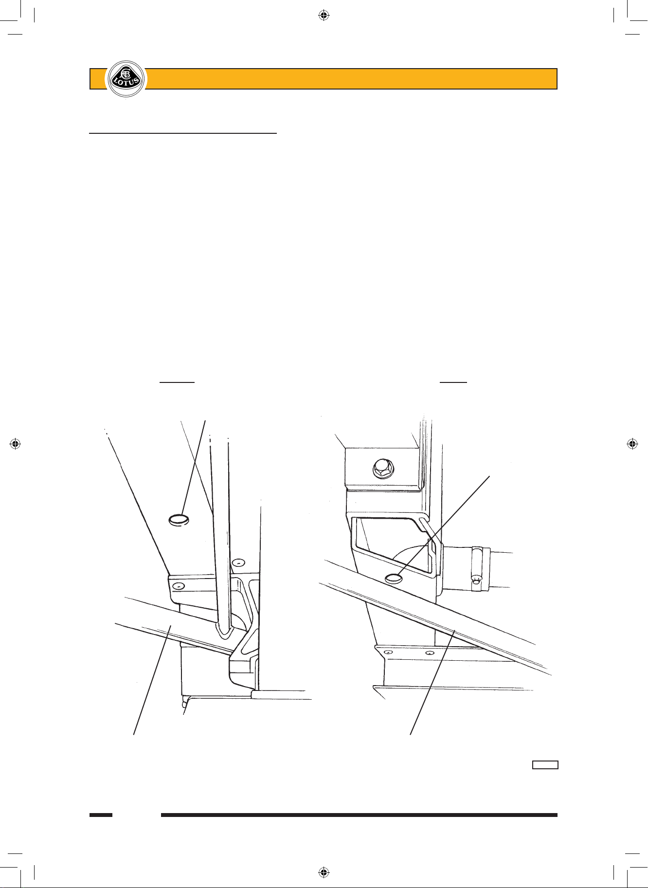
AH.2 - CHASSIS STRAIGHTNESS CHECK
In the absence of visual damage, the chassis may be checked for twist or distortion by utilising the tooling
holes in the underside of the main side rails. If computer processed laser measuring equipment is not avail
able, manual checks can be made with reference to an accurately level ground plane, e.g. an accurately set
and maintained suspension geometry ramp/lift. Position the car on the lift, and proceed as follows:
1. Identify the tooling holes in the lower surface of each chassis main side rail. At the front end, between the
suspension wishbone pivots, and at the extreme rear end of each rail.
2. Measure the height of each tooling hole above the reference plane and use jacks to adjust the height of
the chassis in order to equalise any three of these dimensions.
3. Measure the deviation of the fourth dimension from the other three.
Maximum service deviation = ± 2.0 mm.
4. Repeat operations (2) and (3) for each combination of corners to result in four values for the 'fourth' dimen
-
sion deviation. If any one of these exceeds the service specification, the chassis should be considered
damaged and replaced by a partial body assembly.
FRONT REAR
Tooling hole
Tooling
hole
Front wishbone Rear wishbone
a27/27a
sn_ah_cyclone.indd 4 03/03/2006 10:51:14
Page 23
Page 5
Lotus Service Notes Section AH
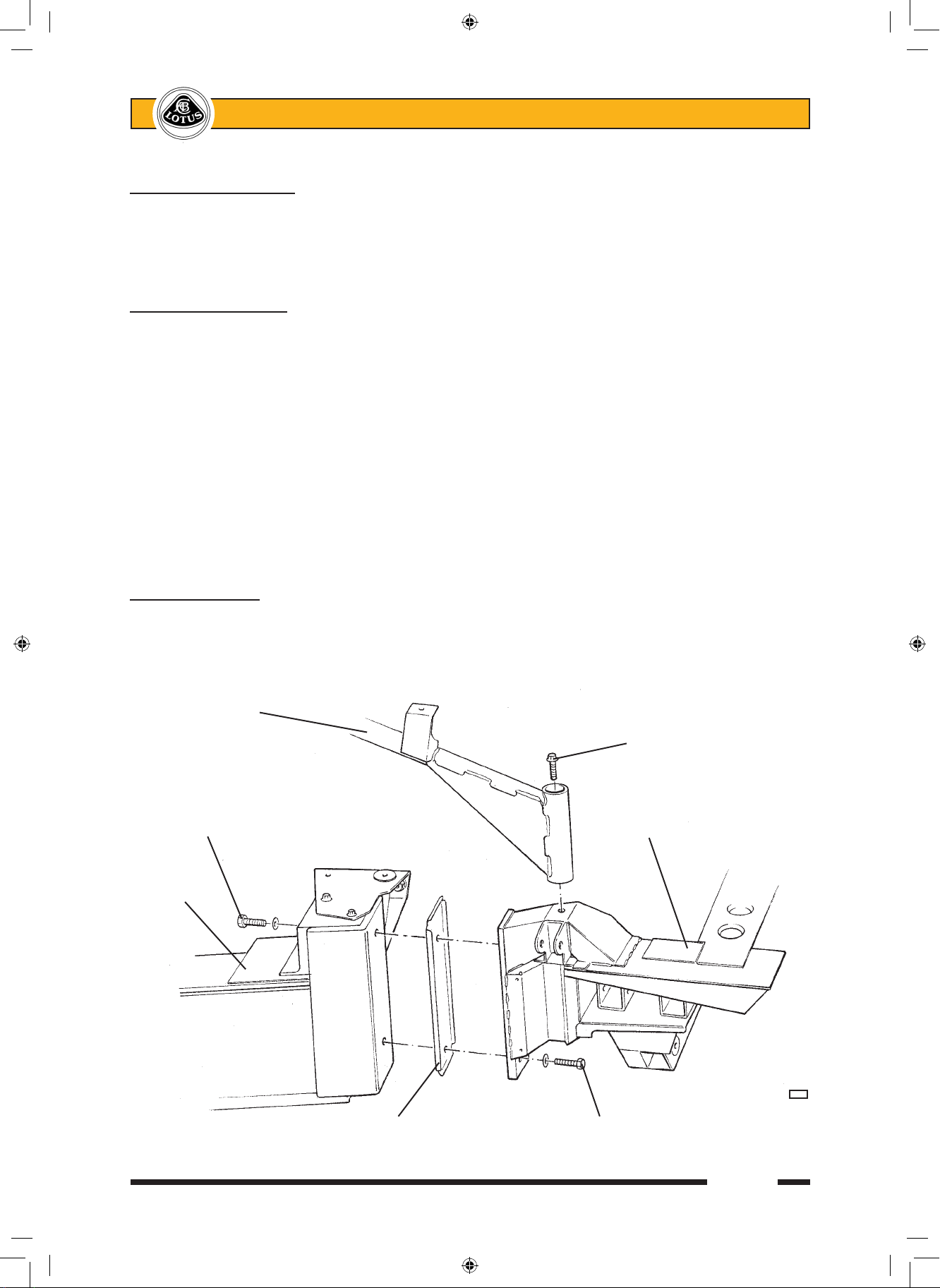
AH.3 - REAR SUBFRAME
The rear ends of the chassis siderails are linked by a fabricated sheet steel subframe which provides
mountings for the rear body section, rear suspension pivots, engine rear stabiliser, exhaust muffler and seat
belt mounting frame struts. The subframe is secured to the siderails by two M12 bolts at each side, with an
anti-corrosion shim plate interposed.
To remove rear subframe
1. Remove the rear clamshell (see section BR).
2. Remove exhaust heatshields, catalytic converter and muffler.
3. Disconnect the parking brake cables, wheel speed sensor harnesses and rear brake hydraulics. Release
the driveshafts from the hubs, and remove both rear suspension assemblies complete, providing alterna
-
tive support for the driveshafts.
4. Disconnect the inertia switch, and release from the subframe the oxygen sensor harness, wheel speed
sensor harnesses and brake pipes.
5. Release the engine rear stabiliser mounting from either the subframe or transmission.
6. Release the roof hoop backstays from the subframe. Remove the two bolts each side securing the sub
-
frame to the chassis flange and withdraw the subframe from the car.
Fitting rear subframe
When bolting the subframe at each side to the chassis rail rear flange, ensure that the anti-corrosion
shim plate is interposed. The lower fixing bolts should be inserted from the rear, using a washer and Nyloc nut
inside the chassis extrusion. Apply Permabond A130 (A912E7033V) to the threads of the upper bolts before
fitting from the front into the weldnuts in the subframe. Tighten all four bolts to 86 Nm. Continue re-assembly
in reverse order to disassembly.
Seat belt mounting
frame backstay
Backstay to subrame
fixing bolt
Subframe upper
mounting bolt Rear subframe
Chassis
a30
Anti-corrosion shimplate Subframe lower mounting bolt
sn_ah_cyclone.indd 5 03/03/2006 10:51:14
Page 24

Page 1
Lotus Service Notes Section BQ
BODYCARE & REPAIR
SECTION BQ
Sub-Section Page
General Description BQ.1 3
Lotus Composite Body Features BQ.2 3
Bodycare BQ.3 4
Accident Damage Assessment BQ.4 5
Body Panel Bonding Materials BQ.5 6
Replacement of Bonded-On Panels - General BQ.6 9
Front Crash Structure BQ.7 10
Windscreen Frame BQ.8 12
Sill Panels BQ.9 16
Rear Bulkhead BQ.10 17
sn_bq_cyclone.indd 1 03/03/2006 10:53:38
Page 25
Page 2
Lotus Service Notes Section BQ
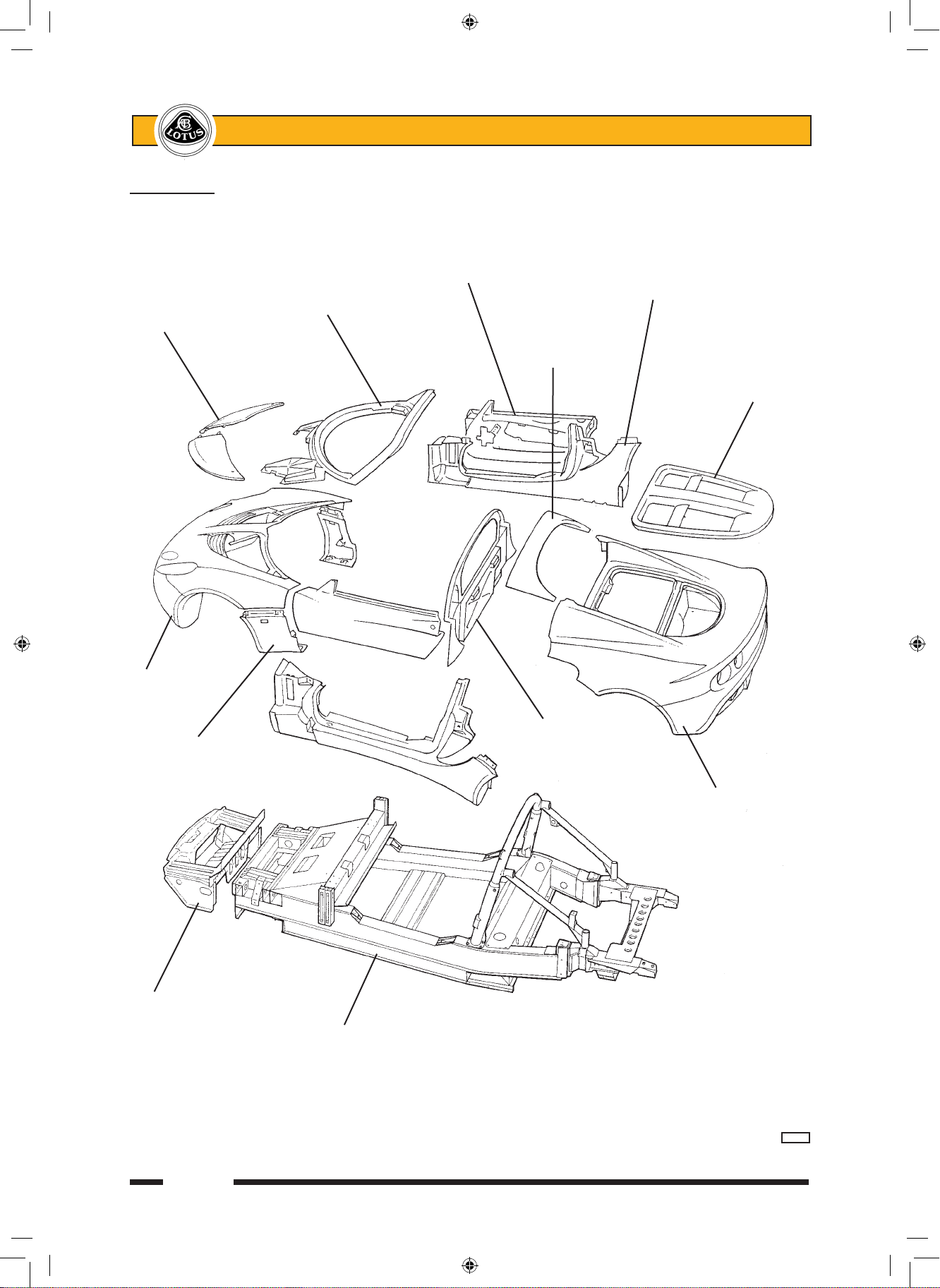
Body Panels
Door
shell
Windscreen Sill panel
Front access frame
panel Rear
window
shroud
Engine
cover lid
Front
clamshell
Cabin rear
Door hinge bulkhead
cover panel
Rear clamshell
Front crash
structure
Chassis frame
b277b
sn_bq_cyclone.indd 2 03/03/2006 10:53:38
Page 26

Page 3
Lotus Service Notes Section BQ
BQ.1 - GENERAL DESCRIPTION
The body panels of the Lotus Elise are constructed of composite materials, with the external panels not
being required to contribute to chassis rigidity. The panels are attached to the aluminium chassis and/or other
body panels either by elastomeric polyurethane adhesive, or in the case of the front and rear clamshells, are
bolted on for ease of dis-assembly and access to chassis parts. The composite mouldings are manufactured
by one of several processes (see later) dependent on application, with a nominal thickness of 2.2 - 2.5 mm.
The windscreen frame incorporates foam beams to create closed box sections for optimum strength and a
‘crash structure’ bonded to the front of the chassis incorporates longitudinal box sections to provide specific
crush characteristics and absorb crash impact by progressive collapse. This structure also acts as a mounting
and duct for the engine cooling radiator which is mounted horizontally on its top surface.
BQ.2 - LOTUS COMPOSITE BODY FEATURES
Composite structures have the ability to absorb high impact loads by progressive collapse, with impact
damage being localised. In vehicle accidents this feature protects the occupants from injurious shock loads and
greatly reduces the danger of entrapment by deformation of steel body panels. This behaviour also facilitates
repair by either replacing the damaged bonded or bolt on panels, and/or integrating a replacement section
with the undamaged area, using recognised approved methods which restore the panel to its original condition
without residual strain or distortion.
The manufacturing process enables the thickness of composite mouldings to be varied in order to provide
efficient structures of high strength and low weight. Composites will not corrode, so the strength of composite
components is retained regardless of age, unless physical damage is sustained. On the Elise, the body construction features an assembly of mouldings to form a single piece for the whole of the nose and front wings,
and a similar assembly for the whole of the rear body aft of the doors. These two 'clamshells' are fixed using
threaded fasteners to permit easy removal for access to chassis or powertrain components, or to allow simple
and economic accident repair. Other composite mouldings include the door shells, sills, front compartment
lid, windscreen frame and rear bulkhead, some panels being bonded to the aluminium alloy chassis with an
elastomeric adhesive.
A composite panel may return to its original shape after deflection, but beyond a certain level of flexibility,
such treatment may result in the formation of surface cracks which may not be immediately apparent due to
the masking effect of the paint film. A steel panel similarly treated would become dented or deformed. The
cracking may be confined to the surface layer with no reduction in panel strength, but if the damage is more
severe the composite structure below the surface may be weakened. Localised repairs can be made in either
case. Possible causes of surface cracking include:
- Vehicle collision;
- Sitting, leaning heavily or pushing on the body or any composite panel;
- Knocking doors against obstructions when opening;
- Dropping objects onto a panel;
- Allowing unrestrained items to roll about in a luggage compartment;
- Fitting a front access panel or closing the engine cover onto projecting objects, e.g. luggage or tools;
- Applying excessive force to parts attached to composite panels e.g. mirrors, locks, aerial etc. (inc. action
byvandals).
- Incorrect jacking.
The composite body panels of the Elise are manufactured by one of several processes dependent on the
requirements of the panel concerned:
- The front and rear clamshells, sill panels, windscreen frame, door outer panels, hard top roof outer panel
and front crash structure are produced by Injection Compression System Resin Transfer Moulding (ICS
RTM), whereby a mix of polyester resin and glass fibres is injected into a heated, chrome steel surfaced,
closed mould. After filling, the gap between the two halves of the mould is then reduced in order to compress the moulding and ensure complete material flow and consistent structural quality. Panel thickness
is a nominal 2.2 mm. The absence of the 'gel coat' used with other processes results in much greater
resistance to surface damage, and minimum surface preparation for before painting.
sn_bq_cyclone.indd 3 03/03/2006 10:53:38
Page 27

Page 4
Lotus Service Notes Section BQ
- The front access panels, engine cover lid, door hinge panels, door and roof inners and rear window shroud
are produced from Low Pressure Sheet Moulding Compound (LPSMC), whereby flat sheets of composite
material are formed using heated, chrome steel surfaced moulds to produce panels with a nominal thickness of 2.5 mm.
- A third process is used for the cabin rear bulkhead, bootbox and radiator mounting panel where the panel
surface is not primarily visible. These panels are produced by a Polyurethane Structural Reaction Injection Moulding (PU SRIM) process.
- Body panels unique to the Exige model, including front and rear clamshells, door hinge cover panels and
tailgate panel, are 'hand lay' composite mouldings with a nominal thickness of 2.5 mm.
Whichever production process applies, conventional composite repair techniques can be used to rectify
structural or surface damage whenever repairs can be determined as being more economic than panel replacement.
BQ.3 - BODYCARE
The acrylic enamel paint finish of the Elise is extremely resistant to all normal forms of atmospheric attack.
Following the simple maintenance procedure summarised below will help retain the gloss, colour and protective
properties of the paint throughout the life of the vehicle. However, car finishes are not immune to damage, and
amongst the more common causes of deterioration are:
- Atmospheric contaminants; dust, soot, ash, and acidic or alkaline aerosol mist can chemically attack
paint.
- Abrasion; blowing sand and dust, or a dirty washing cloth.
- Tree sap and insect fluids; can form a water-insoluble polymer that adheres to the paint.
- Bird excrement; highly acidic or alkaline, they can chemically etch the paint. Wash off immediately.
- Leaves; contain tannic acid which can stain light finishes.
- Impact damage; granite chippings thrown up from poor or recently dressed road surfaces can subject the
body to severe localised impact, and result in paint chips, especially around the vulnerable frontal panels.
Do not follow other vehicles too closely in such circumstances.
Washing
Lotus recommends that the car be hand washed, using the following instructions:
Many contaminants are water soluble and can be removed before any harm occurs by thorough washing
with plenty of lukewarm water, together with a proprietary car wash additive (household detergent and washing
up liquid can contain corrosive salts, and will remove wax and accelerate oxidation). Frequent washing is the
best safeguard against both seen and invisible contaminants. Wash in the shade, and use a cotton chenille
wash mitt or a sponge rinsed frequently to minimise entrapment of dirt particles. Use a straight back and forth
washing motion to avoid swirled micro scratches, and rinse thoroughly.
In order to minimise degradation from road salt, the underside of the chassis should be rinsed with clean
water as soon as possible after driving on treated roads. Many fuel filling stations offer pressure washing facilities ideal for this purpose, but to not use on the painted bodywork or soft top roof.
Soft Top Roof:
1. Careful vacuuming of the soft top before washing may be helpful in removing excess dust and other foreign
particles.
2. Wash in partial shade rather than strong sunlight, and wet the whole car before tackling the soft top.
3. Using only clean lukewarm water and a sponge (a chamois or cloth will leave lint, and a brush may abrade
the threads) wash the entire top uniformly. Do NOT use a detergent, which may affect the waterproofing
properties of the material.
4. Rinse the whole car to remove all soap from the fabric and to prevent streaking on the car bodywork.
5. Remove surface water with a sponge and allow to air dry in direct sunlight. Ensure that the roof is fully dry
before stowing, as prolonged stowage of a wet or damp roof will promote rotting of the fabric.
Keeping the soft top clean by regular washing will enhance the life and maintain the appearance of the
roof, and facilitate subsequent cleaning. The use of stronger cleansers should be left to professionals experi-
sn_bq_cyclone.indd 4 03/03/2006 10:53:39
Page 28

Page 5
Lotus Service Notes Section BQ
enced in handling this type of fabric as discoloration and degradation of the special protective inner layer may
result. The application of wax finishes, dressings or preservatives will cause stains which are difficult to remove
and therefore should be avoided.
Paintwork Polishing
Eventually some loss of gloss, and an accumulation of traffic film, will occur. At this stage, after normal
washing, the application of a good quality liquid polish will restore the original lustre of the paint film. Higher
gloss of the paint finish, and added protection against contamination, can be obtained by the use of a wax
polish; however, this can only be used successfully on a clean surface, from which the previous application has
been removed with white spirit or a liquid polish cleaner.
Ventilation
Water lying on the paint surface for a lengthy period will eventually penetrate the paint film. Although the
effects will not be visible immediately, a deterioration in the protective properties of the paint film will ultimately
result. It is not recommended to store a wet car in a poorly ventilated garage. If good ventilation cannot be
provided, storage outside on a hard standing or under a carport is to be preferred.
BQ.4 - ACCIDENT DAMAGE ASSESSMENT
The repair method to be employed in the rectification of accident damage to composite panels, is to be
assessed reletive to the particular panel and its method of attachment:
Bolt-on Panels: - Front Clamshell;
- Rear Clamshell;
- Door Shells;
- Front Body Access Panels;
- Engine Cover Lid;
- Door Hinge Cover Panels;
- Rear Window Shroud;
- Hard Top Roof.
These panels are secured by threaded fasteners and are easily removed for access to the back of any
damaged area for repair by conventional composite techniques. Instructions for the removal and refitment of
these panels are contained in section BR.
Bonded-on Panels: - Windscreen Frame;
- LH & RH Sill Panels;
- Front Crash Structure;
- Rear Bulkhead
These panels are bonded to the chassis or to other panels using a flexible polyurethane adhesive which
must be cut before the panel may be removed. In some cases, it may be necessary to partially remove another
panel before the subject panel can be released. It is not generally economic to attempt to remove a bonded
panel intact for later re-fitment.
The integrity of the front crash structure is crucial to the safety of the car in a frontal collision, and it is rec-
ommended not to attempt any major repair of this component. The damaged structure should be cut from the
front of the chassis, and a new assembly bonded into position. The shape and positioning of the windscreen
frame is crucial to the fit of the windscreen and sealing of the soft top roof, such that the only repairs which
should be considered for this panel are cosmetic and superficial; any structural damage should entail panel
replacement.
The sill panels include the ‘A’ and ‘B’ posts, and involve much labour time to replace. Localised repairs
should be performed whenever possible, although access to the inside surface of some parts of the panels is
not freely available.
Note that if damage is such as to require replacement of the chassis, replacement chassis assemblies are
provided only as a 'partial body assembly' which includes jig bonded front crash structure, windscreen frame,
side sills and rear bulkhead. The roof hoop and rear subframe are also included, as are the pipes, hoses and
cables routed through the sills.
sn_bq_cyclone.indd 5 03/03/2006 10:53:39
Page 29

Page 6
Lotus Service Notes Section BQ
BQ.5 - BODY PANEL BONDING MATERIALS
The materials used for bonding the body panels are manufactured by Dow Chemical, and in order to
maintain the structural integrity of the vehicle, and in the case of the front crash structure, the safety, it is most
important to use only the specified materials. The surface preparation and cleaning and priming operations are
crucial to the performance of the adhesive, and must be followed in detail. The products to be used depend on
the surface (substrate) onto which they are applied, and the following list identifies each application:
Anodised aluminium (e.g. chassis and components)
Cleaner: Betawipe VP 04604 Lotus part no. A082B6150V
Primer: Betapnme 5404 Lotus part no. A082B6337V
Adhesive: Betaseal 1701 Lotus part no. A082B6281F
or Betamate E2400 Lotus part no. A082B8415V
Unpainted or painted composite
Cleaner: Betaclean 3900 Lotus part no. A100B6008V
Primer: Betaprime 5404 Lotus part no. A082B6337V
Adhesive: Betaseal 1701 Lotus part no. A082B6281F
or Betamate E2400 Lotus part no. A082B8415V
Zinc plated and passivated steel
Cleaner: Beatclean 3900 Lotus part no. A100B6008V
Primer: Betaprime VP 01706 A+B Lotus part no. A100B6070V
Adhesive: Betaseal 1701 Lotus part no. A082B6281F
Glass
Cleaner: Betawipe VP 04604 Lotus part no. A082B6150V
Primer: Betaprime 5001 Lotus part no. A100B6009V
Adhesive: Betaseal 1701 Lotus part no. A082B6281F
or Betamate E2400 Lotus part no. A082B8415V
Uncoated Lexan/Perspex
Cleaner: Abrasion & dry wipe
Primer: Betapnme 5404 Lotus part no. A082B6337V
Adhesive: Betaseal 1701 Lotus part no. A082B6281F
or Betamate E2400 Lotus part no. A082B8415V
Residual adhesive (i.e. rebonding to surface after cutting off old panel)
Cleaner, primer
& re-activator: Betawipe 4000 Lotus part no. A082B6355V
Adhesive: Betaseal 1701 Lotus part no. A082B6281 F
or Betamate E2400 Lotus part no. A082B8415V
Applicator Bottle
An applicator bottle is available for use with some cleaners and primers, and has a disposable felt pad
which should be changed regularly to minimise surface contamination:
Applicator bottle: A000Z1071F
Cap: A082B6353S
Felt pad: A082B6354S
Product Usage
BETAWIPE VP 04604 (A082B6150V):
Description: Activator and cleaning agent used to promote adhesion to the substrate surface. Supplied in
a 250ml aluminium container with a YELLOW coloured cap.
Application: - Wipe on/wipe off type.
- Pour Betawipe VP 04604 into applicator bottle, and immediately refit the yellow cap onto the
container.
sn_bq_cyclone.indd 6 03/03/2006 10:53:39
Page 30

Page 7
Lotus Service Notes Section BQ
- Push the applicator head onto the bottle, and fit the felt pad.
- Wet out the felt pan by inverting the applicator bottle and gently squeezing the sides.
- Wipe the pad over the substrate surface using minimal pressure to wet the surface.
- Immediately wipe off the activated/cleaned surface using a clean fibre free cloth, and dis-
card.
Notes: - If the substrate is very dirty, first wipe off the surface with a clean fibre free cloth and dis-
card.
- Do not leave the caps off Betawipe containers. A milky colour indicates moisture absorption,
and the material should be discarded.
- Only decant a sufficient quantity of Betawipe for the job concerned, and never pour material
back into the container from the applicator bottle.
- Change the felt pad at regular intervals to reduce surface contamination.
BETACLEAN 3900 (A100B6008V)
Description: Degreaser and cleaning agent used for the removal of contamination from the substrate surface.
Supplied in 1 litre aluminium container with a BLACK coloured cap.
Application: - Wipe on/wipe off type.
- When substrate is very dirty, first wipe off the surface with a clean fibre-free cloth and dis-
card.
- Dampen a fibre-free cloth with Betaclean 3900, and immediately replace the black cap.
- Thoroughly clean the substrate surface with Betaclean and discard the cloth.
- Wipe off the substrate with a clean fibre-free cloth and discard.
BETAWIPE 4000 (A082B6355V)
Description: Cleaning agent which acitvates the old adhesive layer to accept new adhesive. Supplied in 250
ml aluminium containers with a BLUE cap.
Application: - The residual adhesive bead should be cut with a scalpal to leave an even thickness of ap-
proximately 1 to 2 mm.
- Dampen a fibre-free cloth with Betawipe 4000 and immediately replace the blue cap.
- Thoroughly clean the substrate surface with Betawipe and discard the cloth. Do not wipe
off.
- Allow 2 - 3 minutes flash off time before applying adhesive.
BETAPRIME 5001 (A100B6009V)
Description: Adhesion promotor used to maximise the performance of the bonding between the cleaned
and/or activated surface and the adhesive compound. Supplied in 250 ml aluminium container
with GREEN coloured cap.
Application: - Two steel balls inside the container are provided to assist mixing of the contents when shaken.
Prior to decanting Betaprime 5001, shake the container for at least 60 seconds to disperse the
solid content of the material into suspension.
- Pour the primer into the applicator bottle and immediately replace the green cap.
- Wet out the felt pan by inverting the applicator bottle and gently squeezing the sides.
- Wipe the pad over the activated/cleaned substrate surface to apply a continuous film of
primer.
- Allow to dry for a minimum of 15 minutes before applying adhesive. If adhesive is not applied
with 72 hours, wipe on/wipe off with Betawipe VP 04604.
Notes: - The appearance of the primed areas should be deep black in colour with no streaks or
voids.
To achieve this appearance, apply in smooth continuous uni-directional movement, not short
backward and forward movements. The latter technique results in inconsistent film build.
Rework any poor areas after 5 minutes (tack time), applying in the same direction.
- Replace the felt pad if moisture absorption results in hardening.
- Never return unused Betaprime back into the aluminium container.
sn_bq_cyclone.indd 7 03/03/2006 10:53:39
Page 31

Page 8
Lotus Service Notes Section BQ
BETAPRIME 5404 (A082B6337V)
Description: Adhesion promotor used to maximise the performance of the bonding between the cleaned
and/or activated surface and the adhesive compound. Supplied in 250 ml aluminium container
with RED coloured cap.
Application: - Two steel balls inside the container are provided to assist mixing of the contents when shaken.
Prior to decanting Betaprime 5404, shake the container for at least 60 seconds to disperse the
solid content of the material into suspension.
- Pour the primer into the applicator bottle and immediately replace the green cap.
- Wet out the felt pan by inverting the applicator bottle and gently squeezing the sides.
- Wipe the pad over the activated/cleaned substrate surface to apply a continuous film of
primer.
- Allow to dry for a minimum of 15 minutes before applying adhesive. If adhesive is not applied
with 24 hours, re-activate by applying a further coat of Betaprime 5404.
Notes: - The appearance of the primed areas should be deep black in colour with no streaks or
voids.
To achieve this appearance, apply in smooth continuous uni-directional movement, not short
backward and forward movements. The latter technique results in inconsistent film build.
Rework any poor areas after 5 minutes (tack time), applying in the same direction.
- Replace the felt pad if moisture absorption results in hardening.
- Never return unused Betaprime back into the aluminium container.
BETAPRIME VP 01706 A+B (A100B6070V)
Description: Adhesion promotor used to maximise the performance of the bonding between the cleaned
and/or activated surface and the adhesive compound. Supplied in 250 ml aluminium containers
of component A and component B.
Application: - Thoroughly shake component A container to disperse solid material. Remove the lid from the
component A container and scrape any sediment from the botton of the container. Replace the
container lid and thoroughly shake again to disperse the solid content.
- Pour the required amount of component A into a clean container, and add the same volume
of component B. Replace lids immediately. Thoroughly mix the two components for 45 seconds
minimum.
- Leave the mixed components to stand for 30 MINUTES. (Discard if unused after 8 hours)
- Pour the pnmer into the applicator bottle and wet out the felt pan by inverting the bottle and
gently squeezing the sides.
- Wipe the pad over the cleaned substrate surface to apply a continuous THIN film of primer:
A thin, almost transparent film is all that is required. No attempt should be made to attain a
completely opaque covering.
- Allow to dry for a minimum of 4 HOURS, before applying adhesive.
Notes: - To achieve a continuous thin film of VP 01706, apply in a smooth continuous uni-directional
movement, not short backward and forward movements. The latter technique results in inconsistent film build.
- Replace the felt pad if moisture absorption results in hardening.
- Never return unused Betaprime back into the aluminium container.
BETASEAL 1701 (A082B6281F)
Description: One component moisture curing adhesive, providing high strength, permanently elastic bonds
between various substrates. Supplied in 300 ml aluminium cartridge.
Application: - Remove the cartridge end ensuring there is no damage to the reinforcing sleeve.
- Pierce the neck of the cartridge and screw on the applicator nozzle. Cut the nozzle end to the
required diameter and shape.
- Fit the cartridge into an air assisted gun, and extrude a smooth, even and continuous bead
of Betaseal to the previously prepared substrate.
- Assemble the joint within 5 MINUTES.
Notes: - If the adhesive has to be touched or manipulated for any reason, use only wetted fingers.
sn_bq_cyclone.indd 8 03/03/2006 10:53:40
Page 32

Page 9
Lotus Service Notes Section BQ
BETAMATE E2400 (A082B8415V - 220ml, A100B6258V - 450ml)
Description: Two component chemically curing adhesive, providing high strength, permanently elastic bonds
between various substrates. Supplied in 220 and 450 ml aluminium cartridges.
Application: - An electrically driven Betagun Mk 11 is required to mix and extrude Betamate E2400. Refer
to the operating instructions supplied with the gun.
- Extrude a smooth, even and continuous bead of Betamate to the previously prepared sub-
strate.
- Assemble the joint within 5 MINUTES.
Notes: - If the adhesive has to be touched or manipulated for any reason, use only wetted fingers.
BQ.6 - REPLACEMENT OF BONDED-ON PANELS - GENERAL
Bonded body panels are secured using the Gurit-Essex products ‘Betaseal’ or ‘Betamate’, which are flex
ible polyurethane adhesives which must be cut in order for a panel to be removed. The recommended method
of adhesive cutting is with the use of a pneumatic tool such as the Chicago Pneumatic CP838 PneuNife which
uses a range of differently shaped cutting knives to which is imparted a vibrating action. This tool may also be
used to remove windscreens.
Supplier: Chicago Pneumatic, Utica, New York 13501, USA.
Catalogue no.: CP838 Pneu-Nife
Recommended air pressure: 60 - 90 PSIG (4.0 - 6.2 bar)
Tool air inlet: 1/4” NPTF, 3/8” mm. hose size
Air gun
Betaseal cartridge
bj43
sn_bq_cyclone.indd 9 03/03/2006 10:53:40
Page 33

Page 10
Lotus Service Notes Section BQ
It is not generally practical to remove a bonded panel intact, for later refitment. Consequently, when
necessary, the panel can be cut away for better access to the bonded joint. It is not necessary to remove all
traces of sealant from the joint faces on the remaining panels or chassis, but any remaining sealant must be
securely bonded and no thicker than 1 mm or the fit and joint gaps will be upset. It is essential always to follow
the cleaning/priming/bonding operations meticulously if sufficiently strong and durable bonds are to be obtained.
Always use the specified materials.
BQ.7 - FRONT CRASH STRUCTURE
The front crash structure consists of an upper and lower moulding bonded together and supplied only
as an assembly. It is bonded to the front face of the chassis, and is braced by an alloy undershield screwed
to the bottom front edge of the chassis, and to each lower side of the crash structure. The unit also acts as a
ducting for the engine cooling radiator and a.c. condenser (if fitted) which are mounted horizontally on its top
surface in a bolted-on composite radiator housing. Longitudinal tubes formed in the construction are designed
to produce a particular crush characteristic in order to control the rate of deceleration of the vehicle occupants
in a frontal collision.
Operating handle
Compressed air inlet
Vibrating cutting blade
bj46
Crush tubes Radiator aperture
Crash structure
Airflow to
climate chamber
via cut outs
in tubes
Chassis front face
p84a
sn_bq_cyclone.indd 10 03/03/2006 10:53:41
Page 34

Page 11
Lotus Service Notes Section BQ
To remove the crash structure:
- Remove the front clamshell (see sub-section BR.5).
- Remove the front undershield by releasing the three screws securing each lower side of the structure to
the shield, and the three screws securing the shield to the front lower edge of the chassis.
- Drain the coolant and remove the radiator and pipework (see section KH).
- Remove the driving lamps (if fitted) from the crash structure, along with the towing strut, horn, alarm siren
and wiring harness.
- Use a seal cutting knife to cut the bond between the structure and the front face of the chassis. For access
to some of the bonding areas, it may be necessary to cut away some parts of the structure, rendering the
unit unsuitable for refitment. Take care not to damage the surface of the chassis when cutting the adhe-
sive.
It is not necessary to remove all traces of old adhesive from the chassis, but a uniform surface must be
available for the new adhesive bead. The remaining adhesive must be securely bonded and be cut with
a scalpal blade to leave an even thickness of 1 - 2 mm.
Prepare the new structure for bonding:
- Dry fit the new structure to the chassis, and check that a good fit is achieved. Fettle the structure or remove
old adhesive as necessary until the fit is satisfactory.
- Re-activate the surface of the old adhesive on the chassis using Betawipe 4000 (see sub-section BQ.5),
and clean and prime the bonding area on the new crash structure using Betaclean 3900 and Betaprime
5404 (see sub-section BQ.5).
Bonding surface on chassis
Composite crash
structure
b278a
sn_bq_cyclone.indd 11 03/03/2006 10:53:41
Page 35

Page 12
Lotus Service Notes Section BQ
- Apply a bead of Betaseal/mate adhesive (see sub-section BQ.5) to the bonding surface in the manner
shown.
- Fit the structure to the chassis and press into position to spread the adhesive. Use several clamps around
the joint flange to retain the structure until the adhesive has cured; This will take approximately 4 hours
dependent on atmospheric conditions, with a longer period required in dry atmospheres.
- Fit the undershield, radiator (see sub-section KH.4), front clamshell (see sub-section BR.5) and remaining
parts.
BQ.8 - WINDSCREEN FRAME
The windscreen frame is a single ICSRTM moulding with hollow, foam filled sections, and incorporates a
forward extending buttress at each side to brace the frame against the front chassis. A separate dash baffle
panel is used to bridge the space between frame underside and chassis scuttle, and provide for the routing of
climate control pipework and air ducting, and other services.
Application of
adhesive bead
Betaseal bead
b279
Windscreen frame
Dash baffle panel
Demist air duct
Face level
vent duct
Chassis scuttle
Heater pipe
b282b
sn_bq_cyclone.indd 12 03/03/2006 10:53:41
Page 36

Page 13
Lotus Service Notes Section BQ
The shape of the frame is critical to the windscreen fit, and structural repairs to the frame itself are not
recommended. It is not generally economic to attempt to remove the windscreen frame intact for refitment,
as the elastomeric adhesive bonding the frame to the chassis requires cutting with a reciprocating knife, and
access to the joints is sometimes obscured. The recommended procedure is to cut the frame as necessary to
allow its removal without damage to the dash baffle panel. If the sills are to remain fitted, it will be necessary
to carry out some minor work on the screen buttress to sill panel joint, where a panel overlap occurs.
To Replace Windscreen Frame
1. Remove the front wheelarch liners and front clamshell (see sub-section BR.5), and for improved access,
the two doors.
2. Remove the windscreen (see sub-section BR.14).
3. Remove the instrument binnacle and fascia top panel (see sub-section BR.13), and release the fixings
between dash upper extrusion and screen frame.
4. Release the brake hose/pipe connector at the front end of each buttress on the windscreen frame. Release
all harnesses and other components from the windscreen frame buttresses as necessary.
5. Remove the wiper motor mechanism from the windscreen frame.
6. Use a sealant cutting tool to cut the bond between the windscreen frame buttresses and chassis, and
between the frame and 'B' posts, and between the frame underside and dash baffle panel. Remove the
windscreen frame.
7. Cut the adhesive securing the drainage gutter around the front of the frame, to allow transfer to the new
frame.
8. If the dash baffle panel is to be replaced, the clutch pipe and climate control cables must be released and
threaded through the panel before cutting the adhesive.
Primer band on chassis
Heater pipe grommet
Primer band on baffle
Dash baffle panel
Foam strip
b283b
sn_bq_cyclone.indd 13 03/03/2006 10:53:42
Page 37

Page 14
Lotus Service Notes Section BQ
9. To fit a new dash baffle:
- Ensure the heater feed and return pipes are fitted.
- Dry fit the panel and mark up the bonding surface on the chassis scuttle.
- Prepare and re-activate the surface of the old adhesive on the chassis using Betawipe 4000 (see
BQ.5).
- Clean and prime the upper and lower bonding faces on the new baffle panel using Betaclean 3900 and
Betaprime 5404 (see sub-section BQ.5).
- Apply a bead of Betaseal/mate adhesive (see sub-section BQ.5) to the baffle lower flange.
- Position the panel and press along the length of the joint to ensure sufficient spread of adhesive. Clamp
the panel in position until the adhesive cures.
- Apply self adhesive foam strip A082U6065V to each vertical end face of the baffle panel, wrapping over
onto the top edge and along to the primed surface. Apply a second strip up each vertical face.
10. Prepare the old adhesive bead on the chassis for fitment of the windscreen frame by removing excess
sealant from all the bonding areas on the chassis, sill panels and dash baffle to leave a consistent and
level bonding surface for the new frame. It is not necessary to remove all traces of old adhesive, but a
uniform surface must be available for the new adhesive bead. The remaining adhesive must be securely
bonded and be cut with a scalpal blade to leave an even thickness of 1 - 2 mm.
11. Fit the wiper motor assembly and windscreen washer jets to the windscreen frame.
12. If necessary, fit a new roof side rail latch plate to the windscreen header rail - it is not recommended to
refit a bracket due to the requirement for high surface quality on the bracket.
- If applicable, completely remove any old adhesive from the header rail taking care not to damage the com
-
posite substrate. Lightly abrade the bonding surface on the header rail but do not abrade the bracket.
- Clean the bonding surfaces on the header rail and bracket with Betaclean 3900 (see sub-section
BQ.5).
- Prime the header rail with Betaprime 5404, but do not prime the bracket.
- Generously coat the bonding surface of the bracket, with a 50/50 mix of Betamate 7064S (A116B0159V)
and Betamate 7014 (A116B0158V). Fit the bracket to the header rail and wipe off extruded adhesive with
Betaclean 3900. Position the bracket using tool T000T1422F (RH) or T000T1423F (LH), which sould be
taped to the header rail for at least 30 minutes.
13. Before fitting the windscreen frame, ensure that two setting rods are available for positioning the frame:
- Cut two 670mm lengths of locally sourced 10mm diameter steel rod.
14. - Prepare and re-activate the old adhesive bead on the chassis using Betawipe 4000 (see BQ.5).
- Clean and prime the bonding area on the new windscreen frame with Betaclean 3900 and Betaprime
5404 (see sub-section BQ.5).
- Apply a bead of Betaseal/mate adhesive (see sub-section BQ.5) to the whole of the bonding flange on the
windscreen frame and butresses, including the mating face between frame underside and baffle panel.
- Carefully fit the windscreen frame onto the chassis and press into position to ensure adequate adhesive
compression. Ensure the frame is positioned correctly in relation to the roll-over bar by fitting the two setting rods in the roof siderail locating slots. The rods should locate snugly in the slots with no end play.
- Clamp the frame into position until the adhesive cures.
- Ensure good adhesion between the frame and baffle panel.
- Use a spatula to smooth out or remove any excess or extruded adhesive.
15. Seal the frame panel to the top of the door hinge post at each side by extruding a bead of Betaseal, and
smoothing with a spatula to obtain a neat finish.
16. Examine the whole of the bonding jointline for sealing integrity, and if necessary apply additional adhesive
to seal any gaps. Use a spatula to smooth any visual areas to a neat finish.
17. Do not disturb the frame until the adhesive has fully cured (see sub-section BQ.5).
18. Fit the windscreen (see sub-section BR.14), dash panel and instrument pack (BR.13), front clamshell
(BR.5), and other components as necessary.
sn_bq_cyclone.indd 14 03/03/2006 10:53:42
Page 38

Page 15
Lotus Service Notes Section BQ
Windscreen frame bonding (sills not shown)
Windscreen frame
Windsceen
frame
buttress
Dash
baffle
panel
Bonding path
b281a
sn_bq_cyclone.indd 15 03/03/2006 10:53:42
Page 39

Page 16
Lotus Service Notes Section BQ
BQ.9 - SILL PANELS
The sill panels incorporate the ‘A’ and ‘B’ posts, and are bonded to the chassis, windscreen frame and
rear bulkhead panel. The sill bottom flange, and rear end of the will top flange are bonded into grooves in the
chassis main side rails and it is necessary to cut the sills in the course of their removal: It is not practical to
attempt to remove a sill panel intact for later refitment. If sill damage occurs which is not repairable ‘in situ’,
the sill panel should be renewed.
To Replace Sill Panel
A short section of sill flange underlaps the windscreen frame buttress flange in the front wheelarch area
and requires that some cutting and laminating of the new panel is required on assembly.
1. Remove front and rear clamshells (see sub-sections BR.5, BR.6), dash panel (BR.13) and door hinge
bracket (BR.8).
2. Remove the door latch striker pin and washers, noting the assembly sequence. Remove the door sill trim
panel from the chassis and the door ajar switch from the sill panel.
3. Use a sealant cutting knife to cut the adhesive bead between sill and chassis/body panels.
Note:
- In the front wheelarch area, a short section of the sill flange underlaps the windscreen frame buttress
flange. Unless the windscreen is also to be removed, it will be necessary to cut the sill around this flange
in order to release the sill.
- The bottom edge of the sill, and the rear part of the top edge, locate in grooves in the chassis side frame,
and may not readily be cut out with the sill intact. Cut the sill as necessary to release the panel, and then
remove the remaining edges of the panel from the chassis using a suitable cutting knife.
- Cut the sealant around the door hinge post aperture.
- Cut the sealant between the panel and roll over bar.
Bonding path
Slots in chassis
Door hinge siderail
post
Cut flange
top corner Sill panel
if necessary
bj47a
sn_bq_cyclone.indd 16 03/03/2006 10:53:43
Page 40

Page 17
Lotus Service Notes Section BQ
4. Remove excess sealant from all the bonding areas on the chassis and body panels. It is not necessary to
remove all traces of old adhesive, but any remaining adhesive must be securely bonded and be cut with
a scalpal blade to leave an even thickness of 1 - 2 mm.
5. If necessary, cut the top front corner of the sill flange to allow mating of the panel around the windscreen
butress flange. Dry fit the sill and fettle as necessary to achieve a good fit. Note that a new sill will require
an alloy right angle bracket (A120B0053F) riveting to the rear end of the sill panel to form a bonding surface.
Holes are pre-drilled, with two pairs of holes in the bracket to suit Rover and Toyota powertrain cars. For
Toyota powertrain cars, use the innermost holes in the bracket to pull the sill panel furthest inboard.
6. Before preparing the surfaces for bonding, ensure that the necessary pipes and cables are fitted to the
chassis side rails:
RH side: - heater feed pipe
- brake pipe
- alloy spigot for side impact foam
LH side: - heater return pipe
- brake pipe
- clutch pipe
- servo vacuum hose
- main battery positive cable
- alloy spigot for side impact foam
Check that the following components are fitted into the composite sill:
RH side: - 2 a.c. pipes (if applicable)
- oil cooler return hose (if applicable)
- side impact foam
- foam baffle
LH side: - oil cooler feed hose (if applicable)
- side impact foam
- foam baffle
7. Prepare the bonding surface of the new sill panel with Betaclean 3900 and Betaprime 5404 (see subsection
BQ.5). Prepare surface of the old adhesive bead on the chassis and body panels Using Betawipe 4000
(see sub-section BQ.5).
8. Apply a bead of Betaseal/mate adhesive (see sub-section BQ.5) to the bonding surface on the chassis and
body and fit the sill panel into position, first locating the sill bottom edge into its chassis slot, and press all
around the joint to ensure sufficient spread of adhesive. If necessary, use a spatula to smooth or remove
any extruded adhesive, and to neaten any visual areas. If necessary, add adhesive to the joint around
the door hinge post, and to the windscreen frame, and smooth with a spatula.
9. Clamp the panel into position until the adhesive has cured (see sub-section BQ.5).
10. If the top front corner of the sill flange has been cut to fit around the windscreen butress flange, this area
should be reinforced as follows: Roughen the surface of the windscreen buttress flange and the adjacent
sill panel in the modified area, and lay up two pieces of chopped strand mat across the joint.
11. Refit the dash panel, front and rear clamshells, doors, both wheelarch liners and other components as
necessary.
BQ.10 - REAR BULKHEAD
The rear bulkhead is a Polyurethane Structural Reaction Injection Moulding (PU SRIM), incorporates the
rear window surround, and is bonded to the roll over bar and chassis fuel tank bay. A heat formed polyester
fibre heat/acoustic insulator panel is bonded to the rear side of the panel, and incorporates a glass fibre alu
minised cloth heat reflector shield in the vicinity of the exhaust manifold. The rear window is bonded directly
to the bulkhead using the same materials and procedure as is used for the windscreen.
sn_bq_cyclone.indd 17 03/03/2006 10:53:43
Page 41

Page 18
Lotus Service Notes Section BQ
To replace the rear bulkhead:
1. Remove the rear clamshell (see sub-section BR.6).
2. Remove both seats, and the bulkhead interior trim panel.
3. Remove from the inside of the bulkhead the microwave sensor and immobiliser module. Release all wiring
harnesses from the bulkhead clips.
4. Release all fittings from the roll-over bar backstays (air cleaner, roll over valve) and remove both back
-
stays.
5. Taking suitable precautions, remove the fuel filler hose and filler breather hose, and cap the tank apertures
to prevent dirt ingress and reduce fire risk.
6. Release the evaporative emissions charcoal canister and fuel filter from their bulkhead mounting brack
-
ets.
7. Release the aerial lead from the bulkhead.
8. Using a long knife, cut the adhesive securing the insulator panel to the bulkhead, and remove the panel
to improve access to the bulkhead bonded joint.
9. Using a sealant cutting knife, cut the adhesive bead between the top section of the bulkhead and the roll
over bar, and between the bottom of the bulkhead and the chassis. If the sill panels are fitted, cut the
bond between sill panel 'B' posts and the bulkhead panel.
10. Manoeuvre the bulkhead from the car.
To Fit Bulkhead Panel
Before fitting a bulkhead panel, ensure that the following parts are bonded to the panel:
- Header tank mounting bracket;
- Charcoal canister mounting bracket;
- Immobiliser module stud plate;
- Fuel filter mounting bracket;
- Rear window glass;
All the above components are bonded using elastomeric adhesive applied as follows. Refer also to subsection BQ.5:
Brackets & Studplates: Clean the bonding surfaces on the bracket and bulkhead with Betaclean 3900 (black
cap) and prime both surfaces with Betaprime 5404 (red cap). Apply Betaseal 1701 adhesive to the bracket,
and clamp in position until the adhesive has cured.
Rear Window: Clean the whole of the bonding surface on the glass with Betawipe VP 04604 (yellow cap), and
prime with Betaprime 5001 (green cap). Clean the corresponding surface on the bulkhead with Betaclean 3900
(black cap) and prime with Betaprime 5404 (red cap). Apply a bead of Betaseal 1701 to the periphery of the
glass, and press into position on the bulkhead to ensure sufficient compression of the adhesive. Use a spatula
to remove excess extruded adhesive and smooth any visual areas. Tape the glass into place if necessary to
retain position until the adhesive cures.
Bonding of Bulkhead Panel: Clean the mating surfaces of bulkhead, roll over bar and (if fitted) sill 'B' posts,
with Betaclean 3900 (black cap) and prime with Betaprime 5404 (red cap). Or, where applicable, use Betawipe
4000 to re-activate old adhesive (refer to sub-section BO.5). Clean the mating surface on the chassis with
Betawipe VP 04604 (yellow cap), and prime with Betaprime 5404 (red cap). Apply a bead of Betaseal 1701
to the bonding path on the bulkhead, and manoeuvre into postion, pressing all round the joint path to ensure
sufficient compression of the adhesive. Use a spatula to remove excess extruded adhesive and smooth any
sn_bq_cyclone.indd 18 03/03/2006 10:53:43
Page 42

Page 19
Lotus Service Notes Section BQ
visual areas. Secure in position with tape until the adhesive has cured.
The heat/acoustic insulator panel is bonded to the bulkhead only at its centre section. Clean and prime
the centre section on the bulkhead with Betaclean 3900 and Betaprime 5404, and apply Betaseal 1701. Press
the insulator panel into position and ensure sufficient compression of adhesive. Tape in place until the adhesive
has cured.
Refit remaining components in reverse order to removal.
sn_bq_cyclone.indd 19 03/03/2006 10:53:43
Page 43

Lotus Service Notes Section BR
BODY FITTINGS
SECTION BR
Sub-Section Page
Removable Roof BR.1 2
Rear Window Shroud (Elise only) BR.2 6
Front Body Access Panels BR.3 7
Engine Cover Lid BR.4 7
Door Hinge Cover Panel BR.5 9
Front Clamshell BR.6 9
Rear Clamshell BR.7 11
Door Mirrors BR.8 12
Door Shell Brackets BR.8a 12a
Door Beam & Hinge BR.9 13
Door Shell Assembly BR.10 15
Door Glass, Guide Rails & Winder Mechanism BR.11 16
Electric Windows BR.12 20
Door Seals BR.13 22
Door Latch Mechanism (without CDL) BR.14 23
Central Door Locking BR.15 26
Instrument Binnacle & Dash Panel BR.16 27
Windscreen BR.17 32
Page 1
Page 44

Lotus Service Notes Section BR
BR.1 - REMOVABLE ROOF
The Lotus Elise has been designed to exploit the pleasures of open top motoring, the better to enjoy
exposure to the natural environment, unencumbered by the restrictions and confinement bestowed by a cockpit roof. In order to provide some weather protection to the occupants and vehicle interior, and allow the
continued enjoyment of the car in unfavourable weather conditions, a simple hard or soft top roof may be fitted.
Due to the constantly changing dynamic and wind pressure loadings to which the roof structure is subject
when driving, and the tolerances required to allow for repeated removal and refitting of the roof, complete
weather sealing of the roof cannot be guaranteed, such that some wind noise and minor water leaks are
considered normal for this model. The Elise or Exige should not be subjected to an automatic car wash. Such
machines can induce water leaks caused by high pressure water jets which are not representative of conditions
encountered during normal use. The brushes used may also damage the fabric of the soft top roof.
Exige Hardtop Roof:
The Lotus Exige has been conceived and configured as a sports coupé with a removable roof. The
aerodynamic performance of the bodyshell including the front spoiler, rear aerofoil, roof panel and tailgate
have been tuned to provide the optimum handling balance with the roof scoop on supercharged cars providing
the cooling airflow for the chargecooler.
The roof panel may be removed for better access to the interior for servicing, and the car may be driven
without the roof fitted, but wind buffeting and increased noise levels will be experienced together with a slight
decrease in maximum power on supercharged cars.
Soft Top Roof
A hollow composite roof siderail is used on each side of the car to bridge each top corner of the windscreen frame to the roll over bar, and provide a mounting for a weatherstip seal, against which the top edge of
the door glass abuts. The soft top roof canopy is fixed to each siderail, which uses a spigot pin at the front and
rear to engage with a slot in a latch plate on the header rail and roll over bar. A second, spring loaded spigot pin
at each end of the siderails, is arranged to slide into a ramped hole on the latch plates and secure and tension
the soft top via steel cables running through the front and rear of the roof canopy.
Soft Top - Fitting
WARNING: The soft top roof should be fitted only whilst the vehicle is safely parked.
1. From its stowage bag in the rear luggage
compartment, withdraw the roof assembly
and support stays. Lower both door win-
FITTING ROOF STAYS
dows, or open both doors.
2. Insert the two, identical, roof support stays,
with the arrows pointing forwards, into the
slots above the rear window , and in the wind-
screen header rail. Note that the slots are
Arrows
point forward
keyed to prevent the stays being fitted the
wrong way round.
3. Lay the soft top roof across the centre of
Rear end keyway
the roof space with the arrows on the side
b332
rails pointing forwards.
Page 2
Page 45

Lotus Service Notes Section BR
4. Roll out the left hand side of the roof, and
engage the fixed spigot pin on the front and
rear end of the rail, into the uppermost slot
in the latch blocks at the front and rear of
the roof aperture.
5. Ensure that the tensioning cables at the front
and rear edges of the roof canopy are cor-
rectly located in the channels between the
seal and body before rotating the left hand
side rail downwards.
Ensure that both spring loaded pins ‘click’
FITTING SIDERAIL ohs111
into their ramped slots indicating that latch-
ing is complete. If necessary , ease the latch
handles on the inside face of the side rails
inwards to facilitate latching. Pull up on the
side rail to check security.
6. On the right hand side of the car, repeat steps (4) and (5) for the second side rail, noting that greater
rotating force will be required as tension is applied to the canopy.
Note: Engaging the left hand roof side rail first, will minimise the possibility of the canopy tensioning
cable adjusters causing damage to the roof seals.
Spigot
pin
Spring
loaded
pin
Soft Top - Removal
WARNING: The soft top roof should be removed only whilst the vehicle is safely parked.
1. Open both doors or lower both door win-
dows.
2. On the inside face of the right hand roof
side rail, locate the two latch release levers:
Pull the two lever handles towards each
other to release the side rail latches (press
down on the side rail if necessary to relieve
the load on the latch pins), and rotate the
rail upwards to release the canopy tension.
3. Repeat step (2) for the left hand side rail.
Note: Releasing the right hand roof side
RELEASING ROOF SIDE RAIL ohs112
rail first, will minimise the possibility of the
canopy tensioning cable adjusters causing
damage to the roof seals.
4. Carefully roll up each side of the roof canopy towards the centre, lift off the car, and stow in the roof bag.
5. Unhook the two roof stays and stow in the roof bag.
Important Note: If the roof is not fully dry, it should be stowed for no longer than a few days before unrolling
or refitting and allowing to air dry completely . Prolonged stowage of a wet or damp roof will promote rotting of
the fabric.
Roof Cable - Front: The tension of the steel cable running through the front edge of the roof canopy should be
adjusted with the side rails latched. Hook a spring balance under the centre of the cable, and apply an upwards
force of 6 kgf. Adjust the cable tension to achieve a vertical gap of 6mm between the cable and top surface of
the windscreen surround.
Page 3
Page 46

Lotus Service Notes Section BR
Roof Cable - Rear: The roof rear cable tension should be sufficient only to maintain stability of the roof canopy
shape.
Side Rail Front Latch Plates: The latch plates on the windscreen header rail are secured using a two part
adhesive. If necessary , use Betaclean 3900 (A100B6008V), Bet aprime 5404 (A082B6337V), and a 50/50 mix
of two part adhesive Betamate 7064S (A116B0159V) and Betamate 7014 (A116B0158V) to refix.
Hard Top Roof
Note
- The hard top roof has been designed to provide a seasonal, rather than single trip option. Some owners
may prefer to entrust the fitting and removal of the hard top roof to their dealer.
- When stowing the roof off the car, care should be taken to avoid damage to the roof corners; e.g. use a
suitable soft floor covering on which to stand the roof.
- Fitment or removal of the hardtop is made considerably easier with the assistance of a second person.
- Use only the ‘Torx’ tool supplied in the vehicle tool kit to tighten or release the roof fixing screws.
- The hardtop roof fixings are made captive to the roof to prevent their loss.
Hard Top - Fitting
WARNING: The hard top roof should be fitted only whilst the vehicle is safely parked.
1. Open both doors, and preferably with the
aid of an assistant, lower the roof onto the car
holding aside the loose tethered fixings to avoid
their entrapment or their causing paint damage.
Position the rear edge of the roof first before locating the front edge against the windscreen
header rail.
2. Locate a front spigot bracket into its latch
plate lower slot (lifting the roof slightly to allow
this) and retain to the roof with the Torx bolt. Use
only the special tool supplied, and do not fully
tighten at this stage.
3. Repeat step (2) for the opposite front spigot
bracket.
4. Engage a rear cup bracket with the lower
tongue on its rear latch plate, and retain to the
roof with the Torx bolt. Use only the special tool
supplied, and do not fully tighten at this stage.
Ensure that the cup is fully located onto the
tongue.
5. Repeat step (4) for the opposite rear cup
bracket.
6. Push the roof fully forwards before tightening the front spigot brackets using only the special tool supplied. Hold each rear cup bracket in
alignment whilst tightening the single fixing screw
for each bracket. Do not overtighten.
FRONT
SPIGOT
BRACKET b330
FITTING REAR CUP BRACKET
7. Fit the cover panels to each rear corner of
the roof, noting that the panels are handed for
left and right sides. Press the panels firmly into
position fully to engage the 'Velcro' fixing patches.
Page 4
REAR CORNER
COVER P ANEL
Page 47

Lotus Service Notes Section BR
8. Using the special tool provided, install the
windscreen header cover panel by locating first
with the central screw, and then by the outer
screws before tightening in the same order.
9. Check that the roof is secure by pulling upwards on each corner in turn. If any upward movement is evident, check the correct fitment of all
mounting brackets.
WINDSCREEN
HEADER TRIM
Hard Top - Removal
WINDSCREEN b331
WARNING: The hard top roof should be removed only whilst the vehicle is safely parked.
1. Open both doors.
HEADER TRIM
2. Using the special tool supplied, release the
three T orx screws securing the windscreen header
trim panel, and remove the panel.
3. Using the special tool supplied, slacken the
Torx screw securing each front corner spigot
bracket to the roof, but do not yet remove the
screws.
4. Pull off the trim cover from each rear corner of the roof panel and remove the screw securing the hook bracket to the latch plate at each
rear corner.
FRONT CORNER
SPIGOT BRACKET
b330
REAR CUP BRACKET
5. Remove the two front corner bracket fixing
screws and lift the front edge of the roof slightly
to release the front brackets from their latch plate
slots.
6. With the aid of an assistant, lift the roof from
the car taking care to restrain the tethered brackets to avoid damaging the paintwork.
7. If storing the roof vertically, take care to avoid damaging the panel corners by using a protective floor
covering.
Page 5
Page 48

Lotus Service Notes Section BR
BR.2 - REAR WINDOW SHROUD (Elise only)
The rear window shroud is a body colour composite panel which covers the seat belt mounting frame/roof
hoop, and forms a capping for the rear of the cockpit. The panel is secured by two brackets on its front edge
which are fixed each side by a single M6 screw to the top of the rear bulkhead panel and which are accessible
from within the cabin. On some cars it may be necessary first to remove a trim panel secured by five screws.
Note that Neoprene washers are used between the brackets and the bulhead.
Each rear leg of the shroud is fitted with a captive M6 stud, which locates through a hole in the clamshell
buttress, with the retaining nut accessible either from the engine bay , or wheelarch area. A foam gasket is used
to prevent chafing damage between the shroud and clamshell.
When removing the shroud, it is also necessary to peel off the rear weatherstrip from the front edge of the
panel, and to remove the two cant rail latch plates from their brackets on the roof hoop.
Note that on the Exige, the rear window shroud is an integral part of the rear clamshell moulding.
Roof/'B' post
weatherstip seal
Neoprene
washers
Fixing screw to
rear bulkhead Fixing nut to
rear clamshell
Rear window shroud
Page 6
Foam gasket
pl1020mt
Page 49

Lotus Service Notes Section BR
BR.3 - FRONT BODY ACCESS PANELS
Elise
Two removeable, body colour composite panels are provided in the front body to
allow access to the front fusebox and brake
fluid reservoir.
T o remove an access panel: Use the hexagonal key supplied in the vehicle tool kit (in the
battery cover rear pocket), to release the single threaded fastener securing the outboard
corner of the panel, and withdraw the panel
from the two locating holes in the front body
spine. Guard against the lightweight panel
being blown away and damaged by a strong
wind.
T o refit a panel: Hook the extended lip on the front edge of the p anel beneath the rear edge of the louvre panel
before engaging the two locating pegs on the inboard side of the access panel with the grommeted holes in the
front body spine. Fit the single screw at the outboard corner of the panel into the captive nut in the body , taking
care not to cross-thread or overtighten the screw. Re-stow the hexagonal key in the tool kit.
Note that the outboard fastener uses a mounting plinth adjustable in height to allow optimum panel
alignment to be achieved.
REMOVING ACCESS PANEL ohs93
WARNING: Ensure the access panels are refitted and properly secured before driving.
Exige
The access panels on the Exige model are shorter front to back than those of the Elise, and are retained
by three socket head screws, the outermost of which features an adjustable plinth to allow panel height adjustment.
BR.4 - ENGINE COVER LID
Elise
The engine cover/boot lid is moulded from glass fibre composite and incorporates 4 engine cooling outlet
grilles secured by double sided tape and plastic rivets into recessed apertures. Two hinges are used to attach
the lid to the rear bulkhead, with stud plates fixing the hinges to the bulkhead from the engine bay side, and the
nuts accessible from the cabin after removal of the rear bulkhead trim panel. A single, key operated latch
mechanism secures the lid to a striker pin mounted on the clamshell engine/boot bulkhead. The latch is
released by inserting the ignition key into the lock and turning clockwise, the lock barrel being connected to the
latch mechanism by a short link rod. When the latch is released, a spring plunger will lift the lid sufficiently to
allow it to be raised fully by hand. Support the lid by inserting the prop provided on the boot bulkhead into the
slotted plate adjacent to the latch mechanism. The spring plunger also operates a micro-switch for the alarm
system, and is protected from exhaust manifold heat by a steel shield.
When closing the lid, fully engage the latch mechanism by pressing down on the cover only immediately
above the latch. Note that the lock mechanism plastic cover plate on the underside of the engine lid, serves
also to channel any water ingress from around the lock into the engine bay. Drain holes are provided in the
gutter surrounding the engine bay, with a collector and drain tube fitted at the rearmost extremity.
On USA models, an fluorescent emergency internal release handle is fitted on the underside of the lid to
facilitate the escape of a trapped child.
To remove the engine cover, release the cover from the two identical hinges. Note that the hinges also
serve to clamp the clamshell front edge to the cabin rear bulkhead.
Beware that the engine cover is locked whenever it is closed, and always requires the use of the ignition
key to release. Owners should be made aware of the importance of having a spare key available in case of
inadvertently locking the keys in the boot.
Page 7
Page 50

Lotus Service Notes Section BR
Theaded insert
in engine lid
Engine lid hinge
Studplate clamping hinge &
clamshell to bulkhead
b318
Nut inside cabin
Exige
On Exige models, the double skin, moulded composite tailgate panel, mates with an air intake duct in the
clamshell and roof panel to admit cooling air into the engine bay, and also features seven steel mesh grilles to
allow for the exhaustion of hot air. The tailgate panel uses extruded alloy hinges at its front edge, anchored to
the underside of the clamshell, and is provided with a gas spring strut to support the lid in the fully open
position. The latch mechanism is mounted on the boot bulkhead, where it, and an adjacent alarm plunger
switch are protected by a steel heat shield. The latch is operated by a cable release from a lever handle
mounted outboard of the driver's seat back.
A rear aerofoil with integrally moulded support struts, is secured to the rear end of the tailgate and
transfers loads via adjustable abutments into the boot bulkhead and body structure.
Tailgate release handle
Page 8
ohs141
Page 51

Lotus Service Notes Section BR
BR.5 - DOOR HINGE COVER PANEL
A separate glass fibre composite body p anel is used to fill the area beween the door and wheelarch, and
uses threaded fasteners to attach to the rear of the clamshell, top of the sill and bottom inboard edge of the sill
panel.
To remove a door hinge cover panel:
- From beneath the sill, remove the two fixings securing the bottom edge of the hinge panel to the sill.
- Remove the filler panel concealing the fixing securing the hinge cover to the door sill recess, and remove
the fixing.
- Remove the wheelarch liner and remove the single screw securing the door hinge cover panel to the
clamshell.
- Release the repeater lamp harness and withdraw the panel.
No fixing used Remove front
in this position top fixing
Door
sill
filler
panel
Door hinge
cover panel
Hinge cover to
door sill fixing
Hinge cover to b231
sill underside
BR.6 - FRONT CLAMSHELL
The front clamshell is a bonded assembly of several glass fibre composite mouldings incorporating both
front wings, the front access aperture, radiator air intake and headlamp housings. The clamshell is secured to
the windscreen frame, radiator mounting panel and other panels using threaded fasteners for ease of removal
and to facilitate service access and body repair.
To Remove Front Clamshell
1. Remove both front body access panels.
2. Remove both front wheelarch liners;
Page 9
Page 52

Lotus Service Notes Section BR
Clamshell spine to
Fixing inside wiper motor bracket
headlamp
housing
Clamshell lower front Fixing to
edge to undertray windscreen
frame
Fixing to base of
windscreen pillar
Fixing to radiator mounting panel
(not used with oil coolers) Fixing of door hinge b316
cover panel to clamshell
3. From inside each wheelarch, remove the single screw securing the top edge of the door hinge cover
panel to the clamshell. On cars fitted with front mounted oil coolers, release the hoses from any clamshell
clips around the top of the wheelarch.
4. Via each door aperture, remove the single fixing securing a bracket at the top rear corner of the clamshell
to the base of the windscreen pillar.
5. Remove the fixing at each side securing the clamshell to the bottom of the windscreen frame.
6. Elise: Remove the two nuts securing the clamshell spine bracket to the wiper motor bracket extension.
Exige: Remove the two nuts and bolts securing the clamshell spine to the wiper motor extension bracket,
and the two screws each side securing the clamshell channel to the radiator air deflector panel.
7. If fitted, remove the single fixing at the bottom front of each wheelarch, securing the clamshell to the
radiator panel extension (not used on oil cooler cars).
8. Remove the headlamp cover/mask assembly from each side by releasing the three socket head screws
inside the wheelarch. Remove the clamshell fixing at the front of each headlamp housing. Release the
headlamp harnesses, and feed through the clamshell hole. Disconnect the aerial lead(s).
9. Beneath the nose, release the screws fixing the front lower edge of the clamshell to the alloy undertray.
10. Lift the clamshell from the car. Note any spacing washers or shims fitted at any fixing point.
Page 10
Page 53

Lotus Service Notes Section BR
BR.7 - REAR CLAMSHELL
The rear clamshell is a one piece composite moulding incorporating both rear wings, the engine bay
aperture, rear transom and integral luggage bay. The clamshell is secured to the chassis and other body
panels by threaded fasteners for ease of service access and body repair.
To Remove Rear Clamshell
1. Remove the soft or hard top roof (including Exige) - see sub-section BR.1
2. Remove both rear wheelarch liners;
3. Elise: Remove the rear window shroud - see sub-section BR.2.
Exige: From within the cabin, remove the two screws above the rear window securing the top edge of the
clamshell to the rear bulkhead. Remove the two cant rail latch plates from their brackets on the roof
hoop. Peel off the weatherstrip seal from the clamshell flange.
Boot floor to subframe
Engine lid hinge
fixings
b317a
Fixings to sill
panel and grille
'B' post fixing
from inside
cabin
4. From inside the cabin, remove both seats and the full width trim panel from the rear bulkhead. From the
access thus provided, remove the fixing securing the front end of the clamshell to the 'B' post above the
engine bay air intake.
5. Elise: From inside the cabin, release the fixings securing the engine lid hinges to the rear bulkhead, and
withdraw the engine lid complete with hinges.
Page 11
Page 54

Lotus Service Notes Section BR
6. Release the six (USA market) or eight (other cars) screws securing the fuel filler neck to the clamshell.
Withdraw the filler neck from the clamshell aperture, noting the earth braid secured to the roof hoop
backstay. Keep the filler cap fitted to minimise vapour hazard.
7. Remove the air filter box intake scroll, and from inside each rear wheelarch, release the air intake grille
fixings, and the two screws securing the clamshell to the waistline joint of the sill panel. Withdraw each
grille from its retaining clip.
8. Remove the battery and feed the battery cables through the clamshell grommet. Disconnect the rear
harness and rear lid switch harness from the area behind the battery, and feed through the clamshell
grommet.
9. Remove the rear diffuser panel.
10. From inside the luggage area, release the two screws each side securing the boot floor to the subframe.
11. Unhook the washer bottle.
12. Withdraw the clamshell from the car, noting any spacer pads fitted on the subframe.
13. Refit in reverse order to disassembly with the following notes:
Shimming of clamshell floor mounting points:
It is most important to maintain a gap of at least 7mm between the phenolic resin heatshield rivetted to
the underside of the clamshell boot floor, and the exhaust muffler corrugated heat shield bolted to the subframe. The corrugated shield must touch neither the muffler, nor the clamshell mounted shield, or heat damage may be caused to the clamshell.
On factory build, the subframe is marked adjacent to each of the four clamshell mounting points with the
shim thickness required. Shim plates are available in 1mm and 2mm thicknesses. If a new subframe is being
fitted, or the markings are not visible;
- Use a straight edge across the clamshell rear mounting points on the subframe, and measure down to the
muffler heatshield. Sufficient shims need to be used to bring this dimension to a minimum of 7mm.
- With these shimplates fitted, trial fit the clamshell and if necessary add further shims to optimise the fit of
the clamshell with respect to sill and door shutlines.
- Measure the shim gap at the boot floor front fixing point.
- Remove the clamshell, fit the required shim plates onto the subframe and refit the clamshell.
BR.8 - DOOR MIRRORS
Mirror housing
The manually adjustable, plastic housed
door mirrrors, are mounted via an injection
moulded plinth to the door shell. A spring
loaded ball and socket arrangement provides
a means of mirror adjustment, and a sprung
attachment of the mirror housing to the pivot
socket allows for the mirror to move forwards
or backwards on accidental contact, in order
to reduce the potential for personal injury or
vehicle damage.
b240
Page 12
Mirror glass & surround
Page 55

Lotus Service Notes Section BR
Replacement of mirror glass
The mirror glass is contained in a plastic
surround which is clipped into the housing in
order to provide for convenient and inexpensive replacement. To remove a glass, pull
back the boot between mirror and plinth, and
carefully prise the inboard edge of the mirror
surround from its retaining clips. Working
around the mirror periphery , continue to prise
the surround from the housing taking care not
to damage the paint on the housing. Press
the new glass/surround into the housing until
all the retaining clips are engaged, and reposition the convoluted boot.
Note that convex glass is normally fitted
to both sides, but certain markets, including
the USA, use flat glass in the driver's side,
and passenger side USA mirrors are convex
and etched 'Objects in mirror are closer than
they appear'.
Replacement of mirror assembly
The mirror assembly locates in the plastic injection moulded plinth via two spigots,
and is retained by a single screw tapping into
the lower spigot. To remove a mirror assembly , use a cross head cranked screwdriver, or
similar tool, to remove the screw recessed into
the inside face of the mirror plinth.
Mirror mounting plinth
Mirror assembly
b241a
Mirror fixing screw
Replacement of mirror plinth
The mirror plinth incorporates tapping
plates to accommodate a single screw into the
top leg, and a pair of M5 screws into the bottom leg. The plinth is secured to the door outer
panel with access holes for the three screws
provided in the inner panel, cosmetically con-
b242b
cealed by adhesive patches.
Note that a magnet may be required
when removing or refitting the rearmost screw.
Socket head screw
Adhesive patch
BR.8A - DOOR SHELL BRACKETS
The composite door shell is fitted with various steel brackets bonded to its inner surface in order to mount
the shell to the door beam and also to mount hardware components such as the latch and window lift mechanism. The brackets are bonded to the SMC door structure using ITW Plexus adhesive. If, for whatever reason
a bracket should become detached, the following procedure should be used to re-secure:
1. Remove the failed component from the door.
2. Prepare the bonding surface of the component using emery cloth.
3. If the bracket does not already have holes drilled in the bonding surfaces, use the illustrated examples to
add 6mm holes to the relevent surfaces and provide the adhesive with a good keying feature.
Page 12a
Page 37
Page 56

Lotus Service Notes Section BR
Exterior lock/finger Window rear guide Shell to beam
grip bracket channel bracket front lower bracket
6mm holes 6mm holes b347
4. Prepare the bonding surface of the door panel using coarse emery cloth and clean with Betaclean 3900
(A100B6008V). It is not necessary to remove all existing adhesive if this is securely bonded.
5. Apply a liberal quantity of ITW Plexus MA 920 adhesive (A117B0209V) to the door panel, and within a
maximum period of 4 Minutes (a longer open time will degrade adhesive performance) position the
bracket and ensure that the adhesive is extruded through the keying holes. Remove excess adhesive
which would interfere with any door functionality. Secure the bracket in position for a minimum of 30
minutes to allow adhesive to cure.
6. Re-assemble door and check for correct function.
7. If a latch mounting bracket needs to be rebonded, it is recommended to fit a cup washer A117W4192K
diagonally opposite (i.e. to the latch top mounting screw) to that already used on the inboard lower screw.
BR.9 - DOOR BEAM & HINGE
The door shell is bolted to a hollow section extruded aluminium alloy door beam, hinged at the front end
to the ’A’ post, and carrying the door latch mechanism, via steel brackets, at its rear end. The front end of the
door beam is welded to a second extrusion which forms the rotor of the door hinge. The hinge stator (or hinge
bracket) is bolted to an outrigger on the chassis, and incorporates two cylindrical bearing housings fitted with
maintenance free pivot bushes.
Door hinge adjustments
In order to provide for adjustment of door shutlines, the door hinge may be adjusted in two ways:
i) Height of the hinge, its fore/aft position, and the pivot axis angle (to control the front/rear height align-
ment) may be adjusted after slackening the hinge bracket fixing bolts. The t apping plates for these bolt s
are linked in vertical pairs and are captive, but loose, within the chassis outrigger, and allow for some
vertical movement. Horizontally slotted fixing holes in the hinge bracket allow for fore/aft movement.
ii) Slotted shim plates fitted between the hinge bracket and chassis, allow the in/out door front edge align-
ment to be adjusted in steps of 1 rnm, and by varying the shim pack at the top and bottom pairs of fixings,
the vertical alignment, as viewed from the front, may be adjusted.
Ensure that the clamping load of the hinge bracket to the chassis is not corrupted by the shim plates
bearing against the body. If the surrounding body stands proud of the chassis door hinge outrigger, use a
suitably cut down shim plate to act as a spacer between the chassis and the adjustment shim pack or hinge
bracket.
Page 13
Page 57

Lotus Service Notes Section BR
Door shell to Tapping plate
beam fixing
Shim plate
Chassis
outrigger
Dirt shield
Door beam
(hinge rotor) Door restraint
spring plate
Plastic shoe Hinge bracket b243b
(stator)
Door beam pivot bearings
The door beam hinge uses two maintenance free ’top hat’ section synthetic bearings, pressed into the
hinge stator bracket. Inside each bearing, is fitted a ‘top hat’ section steel rotor bush, clamped to the door
beam extension by an M10 cap head screw threaded into the door beam.
The door beam extension also incorporates a cheek flange which abuts against a rubber strip on the
hinge bracket to limit door opening angle. A spring steel plate fixed to the front of the hinge bracket is designed
to engage around the profiled edge of the door beam abutment flange when the door is fully open, in order to
provide a sprung restraint for the door in this position. A plastic shoe is used over the sliding surface of the
spring plate to provide for maintenance free operation, with the shoe moulding clamped between the spring
plate and chassis. To help protect the hinge mechanism from water and dirt ingress, a plastic shield is push
fitted over the retaining nuts for the spring plate.
To remove the door assembly, or for access to the door pivot components, the two M10 cap head rotor
bush retaining screws should be removed, and the door assembly withdrawn from the hinge bracket. The rotor
bushes and/or bearings may then be withdrawn from the hinge bracket. On re-assembly , note that the bearings
and bushes are assembled dry from above and below the upper and lower housings respectively , and the cap
head screws tightened to 45 Nm. Insert the rubber bungs into the bush ends to inhibit dirt ingress and corrosion.
Page 14
Page 58

Lotus Service Notes Section BR
Rubber bung
Rotor bush
Plastic bearing
Door beam/
hinge rotor
Stator bracket
Cap head screw
Hinge bracket
fixings b244
BR.10 - DOOR SHELL ASSEMBLY
The door shell is mounted on the door beam via three screws through a flange at the front end of the
beam, and by the door latch mounting bracket at the rear end. In order to provide fixing points for the beam,
lock mechanism and other components, the door shell includes various tapping plates and brackets jig bonded
to the inside of the shell, including fixing brackets for the accurate location of the window guide rails.
If a door is to be removed from the car, the preferred method is to release the M10 cap head screws
clamping the upper and lower bushes to the door beam. The beam and door shell assembly may then be
withdrawn from the hinge stator bracket without losing adjustment of the hinge alignment and door shutlines. If
the door shell has to be removed from the beam for repairs or replacement, the beam may be left ’in situ’ and
the door shell slid off the beam using the following procedure:
Removal of door shell from beam
The door shell is secured to the beam via three screws through a flange at the front end of the beam,
tapping into nut plates bonded into the door shell, and via two bolts at the rear end of the door to the door beam
extension bracket. Access to the two bolts securing the extension bracket to the door beam requires that the
door glass first be released:
1. Remove the window winder handle and door trim panel (manual windows) or the door trim panel and
window switch (electric windows).
2. Release the three screws securing the interior release handle, and unclip the control rod from the mecha-
nism.
3. Remove the two M6 and the single M8 screw securing the door beam flange to the front of the door shell
4. Release the three M6 nuts securing the door glass to the lift channel, and separate the glass from the
channel. Tilt the glass as necessary to allow access to the two M8 bolts fixing the rear end of the door
beam to the extension bracket. Remove the bolts and withdraw the door assembly from the beam.
Note that it is necessary to remove the drop glass waist seal before the glass may be withdrawn from the
door.
Page 15
Page 59

Lotus Service Notes Section BR
Beam to extension Door beam Captive Door beam
bracket fixing extension fixing flange
bracket
Door
beam
Door shell to
extension
bracket fixing Door shell to
beam fixing b245a
When refitting the door, take care not to scratch the glass if this is contained in the door. Insert the two
rear bolts securing the beam to the latch bracket, but do not tighten until the three fixings securing the front of
the shell to the beam flange have been fitted and tightened.
BR.11 - DOOR GLASS, GUIDE RAILS & WINDER MECHANISM - Manual Windows
A manually operated door window scissor type lif t mechanism is used in conjunction with two steel guide
rails and a ’frameless’ door design.
The operating principle of the window lift mechanism is that of a scissor linkage, with the front lower end
of the primary leg anchored to the door shell, the lower end of the secondary leg sliding in a horizontal channel
on the door shell, and the upper ends of both legs sliding in a channel fixed to the bottom edge of the window.
The geometry of the system provides for a parallel lift of the glass, where the angle of the bottom edge does not
change throughout the range of travel. An extension to the primary scissor leg carries a toothed sector which
is engaged by a pinion on the window winder. The front and rear edges of the glass are guided by steel rails
which engage with point contact Nylon guide blocks bonded to the glass. The bottom ends of the rails are
adjustable in/out to set the inward tilt of the glass, with the 'up' glass position controlled by an eccentric stop on
the winder mechanism.
Door glass adjustment
To adjust the door glass for optimum weather sealing and ease of operation:
1. Fit the soft top roof and fully raise the window. Check the alignment of the top edge of the glass against
the seal, and the seal compression along the cant rail and up the 'A' and 'B' posts. A light compression is
required; just sufficient to ensure sealing, without imposing loads on the winder mechanism.
2. To adjust the inward tilt of the glass, screw the adjusters at the bottom of each guide rail in or out as
necessary. Access is available without removing the door trim panel. Check that the window glass
moves freely throughout the range of travel.
Page 16
Page 60

Lotus Service Notes Section BR
Door glass
lift channel
Nylon guide
block
Door glass Guide rail Scissor Door Steel guide
tilt top fixing linkage glass rail
Adjuster Handle pinion
screw
Reaction Toothed sector
channel
Threaded
block fixed Door
to rail anchorage
point
Threaded block
fixed to door shell
b285a
Page 17
Page 61

Lotus Service Notes Section BR
3. To adjust the alignment of the top edge of the glass, it is necessary to adjust the height of the reaction
channel. Remove the window winder handle and door trim panel, slacken the reaction channel fixings,
and move the channel up or down as required. Raising the channel will raise the rear edge of the glass.
Mesh friction washer Winder spindle
Eccentric stop
Toothed sector
b274
4. T o adjust the fully up position of the glass, the eccentric stop on the toothed sector of the winder mecha-
nism must be rotated as necessary . A mesh friction washer is fitted between the eccentric and the sector
to help retain adjustment.
To replace the door window glass
1. Remove the window winder handle, and the door trim panel.
2. Release the three fixings securing the slider channel to the bottom of the glass.
3. Do not attempt to withdraw the glass from the door without first removing the door waist seal. Carefully
prise the one-piece seal off the door shell inner and outer flanges, and release the push fixing from the
seal moulding at the rear end of the door. Withdraw the glass from the door shell.
4. Note that new door glasses are supplied complete with jig bonded Nylon sliders and stud plate.
5. Fit the new glass into the door and re-assemble in reverse order to the above.
6. Adjust the glass position as detailed above.
To replace door winder mechanism
1. Remove the window winder handle, and the door trim panel.
2. Release the interior release control rod from the door handle and unclip from the latch mechanism.
3. Secure the door glass in the fully raised position, and release the three fixings securing the winder
mechanism to the door;
- two fixings adjacent to the winder spindle;
- on fixing through the static pivot of the primary scissor arm
4. Manoeuvre the mechanism to free the winder spindle from the door, and to disengage the two upper
sliding bosses of the scissor arms from the window channel, and the lower sliding boss from the static
reaction channel. Withdraw the mechanism from the door.
5. Before fitting a lift mechanism, lubricate the three slider bosses and the sector teeth with Century Luplex
M2 grease (or similar). Fit the mechasnism into the door and engage the three slider bosses in their lift
and reaction channels before securing with the three fixing screws. Note that a single M6 spacer washer
is used between the pivot of the primary scissor arm and the door shell.
Page 18
Page 62

Lotus Service Notes Section BR
Door glass
slider block
Winder mechanism
Lift channel
Door glass
stud plate
b321
Reaction Scissor arm Winder
channel pivot fixing mechanism
fixing
6. Adjust the glass upstop postion, top edge alignment and inward tilt as detailed above.
Door glass guide rails
Two guide rails are used for door glass; one for the front and one for the rear edge. Each of the steel,
black zinc plated, guide rails, is secured by a single screw at the top end to a jig bonded bracket in the door
shell, and by a threaded adjuster at the lower end, engaging in a threaded block fixed to the door shell.
Screwing the adjusters in or out will set the inward tilt of the glass and the contact between glass and door
weatherseal.
To remove a guide rail, first remove the door glass (see above), before releasing the single screw at the
top, and releasing the threaded block from the door shell.
Page 19
Page 63

Lotus Service Notes Section BR
BR.12 - ELECTRIC WINDOWS (Parts List 11.02)
On cars so equipped, switches for the electric windows are mounted in the front of the door trim panels,
and are operative only with the ignition switched on. To help locate the switches in the dark, an illuminated dot
is provided in the ‘down’ button which glows amber when the lights are switched on.
To lower a window, switch on the ignition and press the lower, dished end of the switch in the relevent
door. Release the switch to stop window movement. To raise a window, press the upper, domed end of the
switch.
The electric operation of the door windows comprises;
- An electric motor and winder drum assembly mounted on a bracket which is bolted to the door shell.
- A guide channel for the window lift block, incorporating top and bottom cable pulleys, bolted to the door
shell.
- A single drive cable running from the window lift block, around a guide channel pulley, through a flexible
conduit, around the motor driven winder drum, through another conduit, around the second guide channel
pulley and back to the window lift block.
- An adaptor plate bolted to the stud plate on the lower edge of the door glass.
Viewed from outboard
Upper guide
pulley Window upstop
Window lift block
Drive cable
Motor
mounting
plate
Guide channel
Window
winder Bottom guide pulley
drum
Window lift motor b337
Adaptor plate fitted
to glass
Door Glass Adjustment
- The door glass guide channels and adjustment procedures are the same as used on manually operated
windows. Refer to sub-section BR.11.
- The upstop for the door glass is fitted at the top end of the lift block guide channel in the form of an
adjustable stop screw against which a projection on the window lift bracket abuts.
- The front/rear height of the top edge of the glass may be adjusted at the slot where the front of the window
lift bracket attaches to the door glass.
Page 20
Page 64

Lotus Service Notes Section BR
Replacement of Window Lift Mechanism
The window lift mechanism comprises the motor, drive cable and guide channel assembly as a complete
unit. To remove the mechanism:
1. If possible, raise the window fully for optimum access.
2. Remove the door trim panel and disconnect the window switch. Peel off the plastic water shielding.
3. Release the window lift bracket from the door glass and secure the glass in the fully raised position taking
care not to damage the door waist seals in the top of the door shell.
Guide rail Motor mounting
top fixing bracket fixings
b339
Guide rail
bracket fixings
4. Unplug the motor electrical connector. Release the three fixings securing the motor mounting bracket,
and the two remaining fixings securing the guide channel to the door shell.
5. Carefully manoeuvre the lift mechanism from the door.
6. Refit in reverse order to removal, noting that the motor mounting bracket is fixed directly against the door
shell, but that 4mm plastic spacers are used at each of the three guide rail fixings..
Door shell inner panel
Setscrew and washer
Window lift motor
4mm
plastic
spacer
Threaded
insert
Cable winder Motor mounting Guide rail Guide
drum bracket bracket rail b340
Page 21
Page 65

Lotus Service Notes Section BR
Note that the door glass is common to manually operated windows, with slider blocks bonded to the front
and rear edges, and a studplate channel bonded to the lower edge. For electric window operation, an adaptor
studplate is used to provide two studs for the window lift bracket.
BR.13 - DOOR SEALS (Parts List 11.01)
Drop Glass 'Waist' Seal
The door drop glass waist seal is a single unit comprising inner and outer seal extrusions joined around
the rear end by a moulded capping piece. Each length of seal is pressed onto the top edge of the inner or outer
door panel, with a plastic rivet securing the capping piece. The seal should be removed before withdrawing the
door glass or guide channels from the door.
A 'cheater' seal is bonded to the front and rear faces of the door mirror mounting extension. To fit a new
seal:
- Clean the bonding surfaces on the door shell edges with Betaclean 3900 (A100B6008V).
- Apply Permabond A905 surface conditioner to the bonding surfaces of door shell and cheater seal.
- Apply Loctite 382 adhesive to the inside of the cheater seal and fit onto the door.
Door Weatherstrip
A hollow section rubber weatherstrip is bonded around the door aperture and roof landings to seal against
the door shell and roof. Different seal configurations are used for the door and roof areas, with specially
moulded sections to interface with the roof cantrails. The seal is divided into front and rear sections, with a joint
at the bottom front of each door aperture.
The weatherstrips are manufactured with a self adhesive backing strip. Before fitting a new seal, the
bonding area on the body must be thoroughly cleaned with Betaclean 3900 (A100B6008V). In the critical area
of the 'A' post to windscreen header rail corner, an adhesive promoter 3M 4298UV (A116B6000V) should be
applied along the seal path to to ensure optimum seal retention. Trial fit the seal before peeling off the
protective backing from the adhesive and applying the seal, ensuring that the moulded sections at the cant rail
interfaces are correctly positioned.
When fitting the rear section of the seal, remove the backing strip from the seal in the section around the
latch plate, and fully insert the weatherstrip nodule into the gap between the 'B' post and rear window shroud.
Seal path
Rear window shroud
'B' post
Page 22
Weatherstip seal
Weatherstrip nodule
b335
Page 66

Lotus Service Notes Section BR
Continue to remove the backing strip and stick the weatherstrip along the seal path down the 'B' post and
along the bottom of the door aperture. Cut the seal to mate with the end of the front weatherstrip. Repeat for
the opposite side, and then remove the top section backing strip and secure the seal along the roof shroud
flange. Use a roller wheel along the whole length of the seal to ensure full adhesion.
A secondary 'J' section seal is applied to the front vertical face of the door shell, linking to the cheater
seal.
BR.14 - DOOR LATCH MECHANISM - Without CDL (Parts List 10.17)
Interior release
handle Exterior release
Relay lever button
Interior release assembly
control rod
Exterior
lock
control
Door latch mechanism rod
Bracket, door beam rear b251a
end to door shell
Page 23
Page 67

Lotus Service Notes Section BR
The door latch mechanism is fitted inside the rear face of the door, which is reinforced by a steel plate
bonded to the glass fibre composite door shell. The latch engages with a striker pin which passes through the
composite sill/'B' post moulding, into a captive nut on the roll over bar. An external locking door release button
is mounted via a reinforcing plate, in the top rear of the door outer shell, and transmits its motion around the
rear edge of the door glass to the latch mechanism via two short link rods and a relay lever.
The interior release handle is mounted in the front of the door inner shell, and is connected to the latch
mechanism by a control rod. No interior control of door locking is provided.
Interior Release Handle
- Remove the window winder handle and door trim panel.
- Remove the four screws securing the interior handle assembly and unclip the control rod end clip to allow
the rod to be unhooked from the handle.
- On refitting, ensure that the control rod is located in the guide clips.
Trim panel Door shell
Release
handle
Rod guide clips
Exterior Release Button
- Remove the access disc from the rear
face of the door, and the rod access grommet
lower down.
- Release the two screws securing the lock
assembly and angle bracket to the tapping
plate bonded in the door shell.
- Unclip the link rod from the relay lever,
and withdraw the lock button from the door.
Exterior release
button fixings
(use Permabond A130
A912E7033V)
Control rod access
b260a
Page 24
b255b
Page 68

Lotus Service Notes Section BR
Latch Mechanism
- Remove the window winder handle and door trim panel.
- Unclip the control rod from the interior release handle, and unhook from the latch mechanism.
- Unclip and disconnect the short link rod between the relay lever and the latch mechanism.
- Remove the three M6 screws securing the latch mechanism to the door, and withdraw the latch.
Viewed through outer door skin
Plate bonded
inside
door shell
Control rod to
interior handle
Control rod
to relay lever
Rear b261
Outboard
Control rod to latch
Relay Lever Mechanism
The relay lever components comprise a
shaft with an integral lever on one end, which
connects to the exterior lock button, and a
second lever pinned to the other end, which
connects to the latch mechanism. The shaft
is supprted in two fibre bushes housed on the
bracket connecting the rear end of the door
beam to the door shell. To remove the door
beam extension bracket complete with relay
lever mechanism:
- Remove the window winder handle and
door trim panel.
- Release the three M6 nuts securing the
door glass to the lift channel, and separate
the glass from the channel. Do not attempt to
withdraw the glass from the door without first
removing the door glass waist seals.
- Remove the access grommet from the rear face of the door, and unclip the exterior lock link rod from the
relay lever. Similarly disconnect the link rod between the relay lever and the latch mechanism.
- Support the door shell before removing the two M8 bolts fixing the rear end of the door beam to the end
bracket, and the two screws securing the bracket to the door shell. Remove the bracket complete with
relay lever assembly from the door.
- Refit the bracket in reverse order to removal.
Plain & spring
washers
Pivot bush
Relay lever/shaft
Rod to
exterior
button
b256
Page 25
Page 69

Lotus Service Notes Section BR
BR.15 - CENTRAL DOOR LOCKING (Parts List 10.17)
On cars so equipped, the central door locking (CDL) operates on the driver’s and passenger’s doors in
conjunction with the Cobra 8185/8186 security alarm system. For full details of the alarm system, see subsection MP.1.
To lock the car, remove the ignition key, close both doors and check that the engine cover and front body
access panels are secure. Arm the security alarm in the usual way by pressing once, for a full second, the
larger of the two buttons on the transmitter key. This action will both arm the alarm and electrically lock the
driver’s and passenger’s doors.
If it is desired to lock the doors from inside the vehicle, for example to deter highjack attempts, a CDL
rocker switch is provided on the front of the gear lever shroud which should be pressed to the right to lock both
doors with or without the ignition switched on. Alternatively, the doors can be locked individually by depressing
the button at the rear end of each door sill. Note that whichever locking method is used, the doors will be
‘deadlocked’ such that the interior door release handles are inoperative.
To unlock the doors, press once, for a full second, the larger button on the transmitter key. The alarm will
be disarmed and both doors unlocked. Alternatively, from inside the car, press to the left the rocker switch on
the gear lever shroud to unlock both doors, or raise the sill button on each door. Note that in the event of a
vehicle collision which causes the safety inertia switch to be tripped, the doors will automatically be unlocked.
Notes:
- In the event of a flat vehicle battery, the central door locking will not operate. The doors can be unlocked
only after opening the boot lid and restoring power to the battery by substitution, re-charging or ‘jumping’ to
a second battery.
- To lock the car with a flat or disconnected battery, use the mechanical key in each exterior door button to
disconnect each release button from the latch. This technique does not 'deadlock' the interior release
handles, but does allow continued key access to the car until restoration of battery power.
- To deadlock the car with a flat vehicle bat-
tery, or without the use of the transmitter
or mechanical key , close and lock one door
using the sill button, and for the second
door, hold the exterior release button
pressed in and depress the sill button before closing the door. Access is now available only on restoration of electrical power.
Door sill button
b338
Door Locking Actuator
A CDL actuator is screw fixed to the door
shell below the latch mechanism, and uses a
link rod which passes through the rearmost
(shortest lever length) hole on the latch lever,
before continuing upwards to the door sill button. The latch mechanism within the door is
protected from tamper attempts by a plastic
security shield fixed with screws through the
door shut face. To remove an actuator, remove the door trim panel, security shield, release the two actuator fixing screws, unhook
the actuator from the link rod and disconnect
the harness.
Refit in reverse order to removal, noting
that no adjustment is required.
Page 26
CDL
actuator
Rearmost
hole
Page 70

Lotus Service Notes Section BR
BR.16 - INSTRUMENT BINNACLE & DASH PANEL (Parts List 14.10, 14.05, 14.05b)
The dash panel comprises interlinking alloy extrusions which join the chassis scuttle beam to the base of
the windscreen pillars, and also provide a mounting for the fascia top trip panel. The lowermost extrusion,
which incorporates a curved shelf, is keyed into a slot in the scuttle beam and is secured by rivets at each end
to the beam. On non-airbag cars, two interlinking extrusions are joined by self tapping screws to form the top
part of the dash panel, which is divided into two sections by the steering column. This upper dash is used to
house the face level vents and audio set. On airbag cars, the two upper extrusions are combined into a single
extrusion, which profile and function is similar to non-airbag cars, and which bridges the steering column area
and includes an aperture through which the passenger airbag is deployed.
The upper extrusion(s) slots behind the top edge of the lower dash, and is secured at each end by two
screws to threaded inserts in the base of the windscreen pillars. Additional location is provided by rivets
securing the speaker or door sill trim panel mounting brackets.
On non-airbag cars, a skinned foam fascia top panel, trimmed with suede material, joins the top of the
dash to the base of the windscreen and incorporates the demist ducting and four windscreen outlet vents, with
a moulded plastic capping panel around the front of the fascia top and surrounding the vents. At each end of
the fascia, a moulded plastic panel joins the fascia to the door sill finisher, and is used to mount the front
speakers and lighting switches.
On airbag cars, the untrimmed skinned foam panel incorporates the ducting to the six fixed demist outlet
vents, and also houses the front speakers. The face level vent outlets are housed in the moulded plastic
panels joining the fascia to the door sill finishers and in a central moulding also housing the audio set.
For access to the climate controls, or electrical components mounted on top of the chassis scuttle beam,
the fascia top panel must be removed.
To Remove Fascia Top Panel - non airbag cars
1. Remove the steering column upper and
lower shrouds:
- Remove the four screws securing the
shroud upper section.
- Pull out the grommet from around the
ignition switch and remove the three
screws securing the lower
shroud to the column.
- Disconnect the trip reset button from
the lower shroud.
Lower shroud
mounting
bracket
Column upper shroud
Column lower
shroud
b258a
Page 27
Page 71

Lotus Service Notes Section BR
2. Release the two fixings securing the binnacle mounting brackets to the column, and withdraw the instru-
ment pack and cowl. Unplug the harness connector.
Instrument cowl
Instrument
pack
Binnacle
mounting
bracket
Mounting bracket
fixing screw
b259a
3. Release the screws securing each fascia end (speaker) panel, disconnect the switch and speaker har-
nesses and withdraw the panels.
4. Carefully prise each windscreen outlet vent from the fascia.
5. Remove the screws at each end securing the fascia capping panel, and withdraw the panel.
6. Remove the plastic finisher above the climate controls. Remove the four screws securing the top flange
of the dash extrusion to the underside of the fascia top.
7. Lift the rear of the fascia top to release the two locating bosses from the keyhole slots in the dash, and pull
the fascia rearwards to withdraw the two front edge spigot pins.
8. If the demist ducting is found to have become detached, or loose from the facia top foam moulding, the
duct should be refixed as follows:
- Remove any fixing screws, separate the duct from the fascia and remove any glue from the ducting.
- Roughen the bonding surface of the fascia with sand paper and clean and degrease with Betaclean 3900
or Acetone. Similarly clean and degrease the bonding surface of the demist duct.
- Prime bonding surfaces with Betaprime 5404 and bond with Betaseal 1701 or similar one component
polyurethane adhesive.
Page 28
Page 72

Lotus Service Notes Section BR
Moulded plastic Non-Airbag Type pl1405mt
capping panel
Capping panel fixing
Fascia top panel
Dash fixing
to screen
frame
Column
shroud
Fascia
to dash
fixing
Fascia top FLV/climate
recess finisher control
housing
Keyhole slot
for fascia
Audio set
support
Dash upper
extrusion Fascia top
Upper & centre
extrusions
Dash lower
extrusion
b202a
Chassis
scuttle
beam
Lower
extrusion
Page 29
Page 73

Lotus Service Notes Section BR
Airbag Type
Instrument pack
mounting bracket
Column shroud
support leg Fascia top panel
Column
shroud
Dash fixings
to screen
frame
FLV/audio
housing
Climate
control Airbag
housing door
Airbag shute
Dash upper
extrusion
Dash lower
extrusion Audio set
support
Rivet to scuttle beam pl1405mtb
Page 30
Page 74

Lotus Service Notes Section BR
To Remove Fascia Top Panel - airbag cars
WARNING: The airbag Sensor & Diagnositic Module can maint ain sufficient volt age to cause an airbag
deployment for up to 20 seconds after the battery has been disconnected. Before working on the
airbag system, or in close proximity to an airbag, first take the following precautions to disable temporarily the airbag system:
a. Turn off the ignition.
b. Before disconnecting the battery, use the Lotus Scan tool to read any stored trouble codes.
c. Disconnect the negative (earth) lead from the battery and tape back to ensure that no contact with the
battery negative terminal can be made.
d. Wait for 30 seconds.
e. If working on or near the steering wheel, locate the yellow harness connector alongside the steering
column near the column upper fixing. Unplug this connector. Note that the connector is fitted with
'shorting bars' which automatically interconnect the high and low terminals of the airbag to prevent acci-
dental deployment caused by a voltage differential.
When service work has been completed, reconnect the harness plug and secure with its locking feature,
and reconnect the battery. Ensure the airbag tell tale lights for a few seconds with ignition and then goes out.
1. Column shrouds: Remove the two screws retaining the top part of the shroud, and the four screws
retaining the lower part, and withdraw both parts from the column.
2. Instrument shroud: Pull the instrument shroud backwards to release the four spring clips from their
apertures in the dash panel.
3. Sill top trims: Release the two screws at the bottom of the coin pockets at the front of each sill, and pull
the sill top trim panels from the chassis.
4. Dash end panels: Release the two screws within the top of each coin pocket, and withdraw the switch
panel (driver's side) and blanking panel (passenger side) from the dash end panel. Unplug the wiring
harness from the switch panel.
From within the aperture, release the two screws retaining each end panel to the dash, and pull the panel
rearwards to withdraw the spring clips in the top of the panel from the dash.
5. Airbag door: Pull the airbag door away from the dash, which action will probably require the four retaining
clips to be renewed. Note that the door is constrained by two tether straps.
6. Centre vent panel and radio surround: Release the two screws at each side of the panel and withdraw the
panel from its two spring clips.
7. Fascia top panel: Remove the 5 screws securing the rear edge of the panel to the dash rail, and withdraw
the panel rearwards to disengage the two spigots from the base of the windscreen surround. Disconnect
the speaker cables.
8. Refit in reverse order to removal.
Page 31
Page 75

Lotus Service Notes Section BR
BR.17 - WINDSCREEN (Parts List 11.01)
The laminated windscreen, together with self coloured synthetic finisher moulded around the top and side
edges, is bonded to the composite windscreen mounting frame using Betaseal flexible polyurethane adhesive.
It is not practicable to remove a windscreen from a car and then refit the same glass, as removal of the screen
will require cutting the surround finisher which is available only as part of a new windscreen assembly.
To Replace Windscreen
Parts required:
Windscreen
Betaseal Kit A075B6158F
Plinth, interior mirror mounting
Plinth Adhesive Kit A116U0194S
1. On non-airbag cars, to minimise the possibility of trim damage, remove the fascia end (speaker) panels,
and the fascia top capping panel (around inside base of windscreen).
2. Remove the front clamshell (see sub-section BR.6).
3. Remove the wiper arm from its spindle, and the interior mirror from its plinth.
4. Cut around the whole length of the windscreen surround finisher to allow access to the 'screen adhesive
joint. Apply suction handles to the outside surface of the screen.
5. In order to incur the minimum risk of damage to the windscreen composite mounting frame, the preferred
method of cutting the windscreen adhesive is by the use of a 'cheese' wire. Protect the visual surface of
the windscreen frame with tape before commencing the cutting operation.
Screen removal tool
Cutting wire
Page 32
b322
Page 76

Lotus Service Notes Section BR
6. After cutting out the screen, remove old adhesive from the windscreen frame sufficiently to leave a
consistent and flat surface for the new bond.
7. Clean the whole of the inside surface of the windscreen with a 50% solution of water and isopropanol.
Allow to dry.
8. Fit the interior mirror plinth to the inside of the windscreen using the adhesive kit and instructions sup-
plied.
Windscreen top edge Screen centreline
Obscuration 79mm
band
Mirror position on 63mm 63mm Mirror position on
RHD offset to left LHD offset to right
b263
9. Clean the whole of the inside surface of the obscuration band, and the bonding surface on the windscreen
frame with the wipe cleaner.
10. Apply a 25 mm wide band of Betaprime around the inside periphery of the glass. Similarly apply to the
whole of the bonding surface on the windscreen frame, and to the windscreen bottom laminated edge.
Allow to dry for a minimum of 5 minutes. If the screen is not fitted within 48 hours, the primer should be
re-applied.
1 1. Cut the nozzle of the Betaseal cartridge
to the dimensions shown to produce a
8 mm
triangular section bead. Holding the car-
tridge vertically, extrude a bead of ad-
hesive around the screen, using the edge
of the finisher as a guide along the top
and sides, and following the centreline
10 mm
of the primer band along the lower sec-
tion.
60 mm
b264
Page 33
Page 77

Lotus Service Notes Section BR
12. Cut three 4mm spacer blocks from the material supplied in the Betaseal kit, or from rubber or plastic
material, and position in the inside edge of the adhesive bead running along the bottom of the class.
These spacers are used to control the fitted height of the glass, and the wiper arm clearance.
Cartridge nozzle
Betaseal bead
Edge finisher
Obscuration
band
Primer band
Bead along centre of primer band
Spacer block in inside edge of bead
b265a
13. Using the suction handles, carefully lower the windscreen onto the frame, with the edge finisher firmly
butted against the top and sides off the frame recess. Press around the periphery of the screen to
compress the adhesive until contact with the finisher spacers and bottom edge spacer blocks is felt.
Carefully examine the integrity of the whole length of the joint, if necessary using a spatula to force extra
adhesive into any suspect areas. Wipe off any excess adhesive extruded from the joint, or alternatively,
allow the adhesive fully to cure and cut away any excess using a scalpel blade.
14. Use duct tape and/or support blocks to hold the screen in position and do not disturn until the Betaseal is
fully cured. This will take approximately 4 hours dependent on atmospheric conditions, with a longer
period required in dry atmospheres.
15. Refit wiper arm, interior mirror and front clamshell.
Page 34
Page 78

Lotus Service Notes Section BR
Spillage of material
a) Any spillage of Betaseal onto unprimed glass can be readily peeled off after it has cured.
b) Any spillage onto the bldy can be removed with either Wipe Cleaner No.4, or white spirit.
Shelf life
a) Betaseal primer has a useful life of about 24 hrs. after exposure to the air, after which it starts to become
spongy. If the material is spongy, DO NOT USE. Always use glass primer immediately on opening, and
replace the lid after use.
b) Betaseal has a shelf life of over 6 months at ambient temperature in the original unopened package.
Page 35
Page 79

Lotus Service Notes Section CI
FRONT SUSPENSION
SECTION CI
Sub-Section Page
General Description CI.1 3
Geometry & Adjustments CI.2 3
Anti-Roll Bar CI.3 7
Suspension Disassembly/Assembly CI.4 9
Front Wheel Bearings CI.5 11
For Super Sport Suspension, see DH.6
Page 1
Page 80

Lotus Service Notes Section CI
GENERAL LAYOUT
Spring/damper unit
Top wishbone Steering tie rod
Upper swivel
joint
Track rod
end
Steering
arm
Anti-roll bar
mounting
Anti-roll bar
Bottom wishbone
Hub carrier
Wheel hub
Lower steering swivel joint
Page 2
c34b
Page 81

Lotus Service Notes Section CI
CI.1 - GENERAL DESCRIPTION
The fully independent front suspension comprises, on each side of the car, upper and lower wishbones, a
concentric coil spring/telescopic damper unit, and a tubular anti-roll bar. A forged steel hub carrier, provides a
mounting for a the hub bearing unit to which the road wheel is attached via four spline socket bolts.
The upper and lower 'A' frame wishbones are fabricated from steel tube, the upper wishbone braced by
sheet steel gussets at its apex, and the lower wishbone braced by a tubular strut at its base. The inboard ends
of both wishbones use replaceable bonded rubber pivot bushes to provide maintenance free articulation, with
a specification providing accurate and responsive dynamic characteristics. The outer ends of both wishbones
incorporate housings into which the upper and lower steering swivel ball joints are pressed. The upper ball
pin is secured to the forged steel, rearward facing steering arm, itself fixed to the hub carrier by two M10 bolts.
The ball pin of the lower swivel joint is secured directly into a tapered hole in the bottom of the forged steel hub
carrier. The Bilstein spring/damper unit acts between the outer end of the lower wishbone and the chassis,
and is fitted with the damper rod lowermost in order to minimise unsprung weight.
A forward mounted tubular steel anti-roll bar, is supported in chassis mounted rubber or hard plastic pivot
bushes and is operated via short ball jointed drop links from the lower wishbones.
CI.2 - GEOMETRY & ADJUSTMENTS
Provision is made for the adjustment of wheel alignment, camber and castor. Under normal service conditions, no periodic scheduled check of the geometry is necessary, although a front wheel alignment check is
recommended when the front tyres are replaced. A full geometry check is required only after front suspension
repair, or if excessive tyre wear is evident, or if steering difficulties are encountered. Before any measurements
or adjustments are made it is essential first to set the vehicle to its ‘mid-laden’ ride height, approximating to
driver and passenger and a half tank of fuel. This will require the vehicle to be ballasted, or tied down:
Standard Elise
Mid-laden ride height (reference height for geometry check);
- front 130 mm below front end of chassis siderail
- rear 130 mm below rear end of chassis siderail
Camber - optimum - 0.1°
- tolerance + 0.1° to - 0.3°; Max side/side 0.2°
Castor - optimum + 3.8°
- tolerance + 3.5° to + 4.1°; max. side/side: 0.35°
Alignment - optimum Zero
- tolerance 0.5 mm toe-out to 0.7 mm toe-in overall
(0.07° toe-out to 0.10° toe-in overall)
Steering axis inclination 12° nominal
Sport Elise, Exige
Mid-laden ride height (reference height for geometry check);
- all except USA prior VIN 3013 - front 130 mm below front end of chassis siderail
- rear 130 mm below rear end of chassis siderail
- USA prior VIN 3013 - front 135 mm below front end of chassis siderail
- rear 135 mm below rear end of chassis siderail
Camber - optimum - 0.3°
- tolerance - 0.1° to - 0.5°; max. side/side: 0.2°
Castor - optimum + 3.8°
- tolerance + 3.5° to + 4.1°; max. side/side: 0.35°
Alignment - optimum Zero
- tolerance 0.5 mm toe-out to 0.5 mm toe-in overall
(0.07° toe-out to 0.07° toe-in overall)
Steering axis inclination 12° nominal
Page 3
Page 82

Lotus Service Notes Section CI
Alignment
Wheel alignment refers to the parallelism of the wheels when viewed from above and is crucial to vehicle
stability, handling and tyre wear.
Difference between
rim measurements
= overall toe out
FRONT
Individual
toe out
angle
c26
Alignment is measured either by the angle a wheel makes with the vehicle centre line, or the difference in
dimension between the wheel rim to wheel rim measurement at the front and rear of the wheel at hub centre
height. The wheels are said to 'toe-in' when the wheel paths converge ahead of the vehicle, and 'toe-out' when
they diverge. Wheel alignment is designed to vary with both steering angle (Ackerman) and suspension travel
(bump steer) and should be measured only 'straight ahead' at the specified ride height.
Front wheel alignment is adjusted be screwing the track rods into or out of the track rod outer end ball
joints. In order to preserve the required bump steer characteristic and steering symmetry, the effective length
of each track rod must remain equal - adjust each track rod by a similar amount.
Steering rack gaiter
Track rod end flats
Track rod end
Steering arm
Steering track rod flats
Track rod end locknut
c28a
- Hold the track rod end using the flats provided, and slacken the locknut. Repeat for the opposite side.
- Turn each track rod a similar amount. As a guide, turning both track rods by one quarter of a turn will alter
overall toe-out by approx. 2.0 mm.
- When adjustment is correct, hold each track rod end and tighten the locknuts to 80 - 82 Nm (58 - 60 lbf.
ft).
When slackening or tightening the track rod end locknuts, it is important that the torque reaction is resisted
using the track rod end flats, and that the ball joint itself is not allowed to be stressed.
Page 4
Page 83

Lotus Service Notes Section CI
Camber Adjustment
Camber is the angle from vertical of the wheel when viewed from the front, and is said to be negative when
the wheel leans inwards at the top (positive when leaning outwards). The primary purpose of camber is to
achieve the maximum efficiency of the tyre under cornering loads and body roll, with the specification closely
allied to a particular wheel/tyre combination. The camber angle changes with suspension travel, becoming
more negative on bump, and should be measured only at the specified ride height. Incorrect camber can result
in handling deficiencies and excessive tyre wear.
Camber angle
c29 Vertical Wheel centreline
Camber adjustment is effected by adding or deleting shim plates between the steering arm (to which the
upper steering swivel joint is fixed) and the hub carrier.
Camber adjustment
shimplate
Steering arm
Hub carrier
c30a
- Shimplates are available in 1mm and 3mm thicknesses.
- Reducing the shim pack thickness will increase negative camber. Adding shims will reduce negative
camber.
- A 1mm shim plate will alter camber by approximately 0.25°.
- In March '04 the caphead bolts securing the ball joint plinth to the hub carrier were upgraded from 8.8 to
10.9 grade, with a corresponding increase in torque from 45 to 68 Nm. Before fitting these bolts, inspect
the cap head for the grade marking, apply Permabond A130 (A912E7033) to the threads, and torque
tighten to the appropriate figure.
Page 5
Page 84

Lotus Service Notes Section CI
Castor Adjustment
Castor is the angle from vertical of the steering axis of the wheel when viewed from the side. Its primary
purpose is to provide a natural straight running tendency of the steered wheels with forward vehicle motion.
Castor angles have a complex interaction with other steering geometries and if unbalanced or outside of specification, can result in various stability and handling deficiencies.
FRONT
Top & bottom
steering swivels
Castor angle
c27
The wishbone pivot bushes are bonded rubber type with a plastic flanged outer sleeve, a plain steel in
ner sleeve, and a plastic interleaf sleeve within the rubber bush to control the flexing characteristic. The top
wishbone rear bush, identified by a blue paint mark, has no interleaf sleeve.
The top wishbone pivots are sandwiched between the walls of transverse chassis box sections, the pick
up points in which are reinforced either with machined inserts, or in the case of the foremost position, a thick
alloy plate, each being bonded to the chassis with epoxy adhesive. Spacer washers are fitted ahead of and
behind each of the top wishbone pivot bushes to allow the wishbone to be displaced forwards or backwards,
with an associated change of castor angle. A rubber faced snubber washer fitted against the rear face of the top
wishbone front bush prevents metal to metal contact under extreme braking forces. The spacer washers may
be re-distributed between the front and rear of each pivot bush but the snubber washer position, and the total
shim pack thickness of 4 x 1.5mm at each pivot (inc. the 1.5mm snubber washer) must remain unchanged.
Top Wishbone Inboard Fixing
FRONT
1.5mm shim 1.5mm shim
washers washers Flanged plastic
outer sleeve
Front leg Rear leg
-
Plastic Inner steel
Bonded Bonded interleaf sleeve
plate Rubber faced inserts
snubber washer
Page 6
c32
Page 85

Lotus Service Notes Section CI
Notes
- Shim distribution at the front bush of either wishbone must be copied at the rear bush of that wishbone.
- Transferring a 1.5mm shim washer from ahead of, to behind the pivot bushes, will reduce castor by ap-
proximately 0.4°.
- Transferring a 1.5mm shim washer from behind, to ahead of the pivot bushes, will increase castor by
approximately 0.4°.
- Ensure that the load spreading washers are correctly located beneath the bolt heads and nuts as shown
in the drawings.
- Ensure that the pivot bolts are tightened only with the vehicle at ride height. Torque to 45 Nm.
CI.3 - ANTI-ROLL BAR
Three types of anti-roll bar and chassis mounting have been used:
1. The standard tubular steel anti-roll bar is mounted in pivot bushes onto the front face of the chassis, and
is linked to the outboard ends of each lower front wishbone via short ball jointed links. The bar is mounted
to the chassis using rubber pivot bushes for noise isolation, retained by alloy clamp brackets. Washers
welded to the bar bear against the inner sides of the bushes to provide lateral location of the bar. Castrol
LMX rubber grease, or equivalent, should be used when fitting the rubber bushes onto the anti-roll bar.
Anti-Roll Bar Mounting - Rubber
Spacer plate
Rubber mounting
Clamp bracket
c40
2. On Elise and Exige models built with 'Super Sport' suspension prior to August '06, a stiffer adjustable bar
is used with 5 holes in each end to allow some adjustment of roll stiffness to be made. Standard setting is
centre hole. Using a more forward hole increases stiffness. Two hard plastic clamping blocks secure the
bar to the chassis via the front lower wishbone inboard front pivot bolts, with 'top hat' section steel spacers
preventing the clamps from being crushed. An M5 bolt is used to close the bottom of each clamp.
Anti-Roll Bar Mounting - Hard 1 'Top hat' spacer
Clamping block
M5 bolt
Lower wishbone pivot bolt
Anti-roll bar
c40a
Page 7
Page 86

Lotus Service Notes Section CI
These hard type mountings provide optimum steering response but will transmit more noise and require
periodic lubrication with MoS2 grease at 3,000 mile (5,000 km) intervals. Noise from excessive clearance
may be ameliorated by judicious shaving of the clamping block faces.
2. Elise and Exige models built with 'Super Sport' suspension from August '06, use a yellow painted, standard
rate, 5-hole adjustable bar, sharing the chassis mounting higher position of the standard bar but using
hard plastic bushes housed in alloy clamps. Each split pivot bush incorporates a raised shoulder around
its centre in order to engage with a groove in the two part clamp, and provide lateral location of the bush.
A pip on this shoulder locates in a hole in the clamp cap to prevent rotation of the bush. No lubrication is
required. These hard bushes benefit dynamic response at some penalty to refinement.
Anti-Roll Bar Mounting - Hard 2
Smaller washer Bearing clamp rear
Alignment
dowel Anti-rotation
pip
Cap head bolt
Chassis
front face
Anti-roll bar Synthetic Bearing
split bush clamp
cap Flat washer
Anti-Roll Bar Drop Link
Lower wishbone
Anti-roll bar
drop link
Anti-roll bar
c40b
Page 8
c31
Page 87

Lotus Service Notes Section CI
CI.4 - SUSPENSION DISASSEMBLY/ASSEMBLY
The suspension may be disassembled without the use of any special tools other than a 'Torx' socket for
the hub bearing carrier bolts, and a spring compressor, required only if the spring is to be removed from the
damper unit. With the car on a wheel free lift and with the front wheels removed:
1. Remove the wheelarch liner(s) as appropriate.
2. Remove the two bolts securing the brake calliper to the hub carrier, release the flexible hose from the top
wishbone, and support the calliper aside without straining the brake hose. Release the single countersunk
screw, and remove the brake disc.
3. Remove the nut securing the track rod end into the steering arm, and use a ball joint splitter to separate
the rod end from the arm.
4. Remove the nut securing the top swivel joint to the steering arm, and use a ball joint splitter to separate
the joint from the arm. Remove the two M10 fixing bolts and remove the steering arm from the hub carrier,
taking care not to misplace the camber adjustment shim plates.
5. Remove the nut securing the lower swivel joint to the hub carrier, and use a ball joint splitter to separate
the ball pin from the carrier.
6. Remove the bolts securing the spring/damper unit to the lower wishbone and chassis anchor bracket, and
withdraw the unit, noting the spacer washers fitted at the top end.
7. Disconnect the anti-roll bar drop link from the lower wishbone, and remove the lower wishbone front pivot
bolt.
8. Remove the lower wishbone rear pivot bolt from within the cabin footwell, and withdraw the wishbone.
9. Before removing the two pivot bolts for the top wishbone, take careful note of the distribution of castor
adjustment washers. Move the steering rack to full lock to provide clearance for the withdrawal of the
wishbone rear pivot bolt. Withdraw the wishbone.
10. The wishbone pivot bushes comprise a rubber bush bonded to a steel inner sleeve and a flanged plastic
outer sleeve. The bushes may be pressed out of the wishbone eyes, and new bushes fitted using suit
able press tool dollies. Smear the outer surface of the new bush with IPC 'P-80' rubber lubricant emulsion
(A082C6042V) to ease fitment, and assemble as follows:
Top wishbone - insert from the outside of both pivot eyes (from front of front eye, and rear of rear eye).
Lower wishbone - insert from the inside of both pivot eyes (from rear of front eye, and front of rear eye).
Note that all top wishbone pivot bushes are common with the exception of the top wishbone rear pivot,
which contains no interleaf sleeve and is identified by a blue paint mark.
11. Top and bottom swivel joints are identical, and may be replaced if necessary using a suitable press.
12. If the anti-roll bar is to be removed; remove the front alloy undertray, and, by drilling out the rivets, the
small alloy closing panel at each side of the crash structure below the anti-roll bar. Release the a.r. bar
clamps and drop links, and withdraw the bar.
-
13. The road spring may be removed from the damper using a suitable spring compressor to allow the spring
lower slotted seat to be withdrawn. Note that spring upper seat is located by a square section circlip on
the damper body:
- Standard Elise: Use centre of 3 grooves for mid-laden ride height of 130mm.
- USA Elise: Use lower of 3 grooves for mid-laden ride height of 135mm.
- Elise with sports suspension package and non-USA Exige: Use the upper of 2 grooves for mid-laden
ride height of 130mm.
14. To remove the hub bearing unit from the hub carrier, release the three Torx head bolts and withdraw the
complete unit. The hub unit is not serviceable, and is replaced complete if faulty.
Page 9
Page 88

Lotus Service Notes Section CI
Reassembly
Re-assemble the suspension in reverse order to disassembly with the following notes:
- Take care to assemble each pivot bolt with the correct washers/snubbers/spacers as shown in the dia-
grams.
- Smear the shank of each pivot bolt with PBC grease, but do not allow contamination of the threads.
- Take care to refit the original camber adjustment shimpack, and distribute the castor shims as noted on
removal.
- Top ball joint plinth fixing bolts:
The bolts securing the steering arm/top ball joint plinth to the hub carrier were upgraded in March '04 at
VIN serial number 1537 (approx.) in order to commonise with motorsport applications. Earlier type 8.8
grade bolts should be tightened to 45 Nm; Later 10.9 grade bolts to 68 Nm. The bolt grade is stamped
around the head of the bolt. The thread of both bolt types should first be treated with Permabond A130
(A912E7033V).
- After re-fitting a standard anti-roll bar, ensure that the crash structure closing panels are re-riveted.
- Lubricate the rubber type anti-roll bar mountings with rubber grease and the Nylon type with MoS2
grease.
- Apply Permabond A130 (A912E7033V) to the threads of the steering arm bolts.
- Lubricate the ends of the damper top eye bush with rubber grease.
- Press the brake pedal to reposition the pads before driving the car.
- If the car suffers a suspension impact sufficient to damage a wheel rim, careful attention should be paid to
all related suspension components. Such forces can cause stretching of the lower ball pin and consequent
fixing nut torque loss. As a safety precaution, it is recommended that in all such cases, the lower ball joint
and the two bolts securing the upper ball joint plinth to the hub carrier are renewed.
The Service Schedule specifies that the security of the front and rear suspension is checked at each service.
For cars used on race tracks, or in similar conditions, suspension components and torque checks should be
carried out between sessions. This operation requires that all the principal suspension pivot bolts are torque
checked, noting the following points:
Where a bolt is tapped into a housing or weldnut, and relies on a thread locking compound for security, it
is important to appreciate that if the bolt is disturbed, the locking compound must be re-applied. The following
procedure should be adopted for all such fixings:
- Check the torque of the fixing.
- If the specified torque is attained without the fixing being disturbed (moving), take no further action.
- If the bolt moves, the locking action of the thread adhesive will have been compromised. Remove the
bolt completely, clean off all old adhesive using a wire brush and acetone, and apply new adhesive as
specified.
- Refit the bolt and tighten to the specified torque.
- If for any reason a bolt is found to have become loose, and the car has been operated for any period in
this condition, the bolt should be renewed as a standard precaution and related components carefully
inspected for hole ovality or wear.
Torque Settings:
Upper and lower wishbone pivot bolts 45
Upper swivel joint to steering arm 55
Lower swivel joint to plinth 55
Steering arm to hub carrier - 8.8 grade 45
- 10.9 grade 68
Track rod end to steering arm 30
Damper to lower wishbone 45
Damper to top anchor bracket 45
Damper anchor bracket to chassis 25
Hub bearing unit to hub carrier 90
Brake calliper to hub carrier 45
Anti-roll bar alloy mounting clamps 25
Anti-roll bar drop links 45
Nm
Page 10
Page 89

Lotus Service Notes Section CI
CI.5 - FRONT WHEEL BEARINGS
The sealed front wheel bearings are contained in a steel housing secured to the hub carrier with three
'Torx' bolts. The double row, angular contact, ball bearing is retained in the outer housing and also onto the
hub spigot by a shoulder and a peening operation, and is inseparable for service. Note that all four hub as
semblies are common, and incorporate a wheel speed sensor in the bearing unit, with a flying lead terminating
in an electrical connector plug secured by a camber shim plate bracket.
If there is found to be any discernible free play in the hub bearing, or any roughness or tight spots can be
felt, or any signs of lubricant expulsion are evident, the hub assembly should be replaced - there is no provision for adjustment.
To Replace Hub Bearing Assembly
1. With the wheel removed, release the two fixing bolts, and remove the brake calliper from the hub carrier.
Support clear of the brake disc without straining the flexible hose. Release the single countersunk screw
and withdraw the brake disc from the hub.
2. Using a Torx socket, release the three bolts securing the hub bearing unit to the hub carrier.
3. Fit the new hub bearing unit to the hub carrier and retain with the three Torx bolts. Torque tighten to 90
Nm.
-
4. Refit the brake disc and calliper, using Permabond A130 (A912E7033) to the threads of the calliper fixing
bolts and torque tightening to 45 Nm. Pump the brake pedal to reposition the pads before driving the
car.
Steering arm
Steering arm
Hub carrier
Hub carrier
Hub
Hub
Hub to carrier fixing bolt
Hub to carrier fixing bolt
Swaged bearing retention
Swaged bearing retention
Double row ball bearing
Double row ball bearing
Page 11
c41a
c41a
Page 90

Page 1
Lotus Service Notes Section DH
REAR SUSPENSION
SECTION DH
Sub-Section Page
General Description DH.1 3
Geometry & Adjustments DH.2 3
Suspension Disassembly/Assembly DH.3 6
Rear Wheel Bearings DH.4 9
Track Use Chassis Rear Brace Kit DH.5 11
Super Sports Suspension Package DH.6 14
Page 91

Page 2
Lotus Service Notes Section DH
Rear Suspension Layout
Damper top mount
Upper ball joint
Damper
Hub carrier
Top wishbone
Rear subframe
Rear
subframe
Lower wishbone
Driveshaft
Toe control link
Wheel hub
Road spring
Lower ball joint
d20b
Page 92

Page 3
Lotus Service Notes Section DH
DH.1 - GENERAL DESCRIPTION
The fully independent rear suspension comprises, on each side of the car, upper and lower tubular steel
wishbones, a toe control link, and a concentric coil spring/telescopic damper unit linked between the outboard
end of the lower wishbone and the chassis. A forged steel hub carrier, provides a mounting for the hub bearing
unit to which the road wheel is attached via four spline socket bolts.
The upper and lower 'A' frame wishbones are fabricated from steel tube, with the inboard ends of both
wishbones using replaceable bonded rubber pivot bushes to provide maintenance free articulation, with a
specification providing accurate and responsive dynamic characteristics, with some suppression of noise and
vibration. The two legs of the top wishbone pick up on the chassis rear subframe, and converge outboard
and forwards to a ball joint housing into which is pressed a ball swivel joint. The ball pin of this joint locates in
a forged steel plinth which is itself secured to the hub carrier using two horizontally disposed M10 bolts. The
braced, wide based, lower wishbone, is anchored at its front inboard end to the chassis rear crossmember via
a steel bracket, and at its rear inboard end to the chassis rear subframe. The two legs converge outboard and
rearwards to a ball joint housing which accommodates another swivel ball joint, the ball pin of which is secured
directly into a tapered hole in the forged steel hub carrier. The Bilstein telescopic damper with concentric coil
spring, is fitted with the damper rod lowermost to minimise unsprung weight, and acts between the outer end
of the lower wishbone and an anchorage on the steel subframe.
The adjustable length, double ball jointed, toe control link, shares a subframe anchorage with the rear pivot
of the lower wishbone, and at its outboard end, is secured directly into a tapered hole in a rearward integral
extension of the hub carrier.
The forged steel hub carrier provides a mounting for a hub bearing unit, which is secured by three 'Torx'
head bolts and incorporates a wheel speed sensor for the anti-lock brake system, engine management and
speedometer data.
DH.2 - GEOMETRY & ADJUSTMENTS
Provision is made for the adjustment of wheel alignment and camber. Under normal service conditions, no
periodic scheduled check of the geometry is necessary, with a full geometry check required only after suspension
repair, or if excessive tyre wear is evident, or handling deficiencies encountered. Before any measurements or
adjustments are made, it is essential first to set the vehicle to its ‘mid-laden’ ride height, approximating to driver
and passenger and a half/full tank of fuel. This will require the vehicle to be ballasted or tied down:
Standard Elise
Mid laden ride height (reference height for geometry check);
- all except USA prior VIN 3013 - front 130 mm below front end of chassis siderail
- rear 130 mm below rear end of chassis siderail
- USA prior VIN 3013 - front 135 mm below front end of chassis siderail
- rear 135 mm below rear end of chassis siderail
Camber; - optimum - 1.8°
- tolerance - 1.6° to - 2.0°; max. side/side: 0.2°
Alignment; - optimum 1.2 mm (0.16°) toe-in each side
- tolerance 1.2 to 1.8 mm toe-in each side
(0.16° to 0.24° toe-in each side)
Max. difference side/side: 0.3 mm (0.04°)
Roadsport Elise, Exige (for Super Sport suspension see sub-section DH.6)
Mid laden ride height (reference height for geometry check);
- front 130 mm below front end of chassis siderail
- rear 130 mm below rear end of chassis siderail
Camber; - optimum - 1.8°
- tolerance - 1.6° to - 2.0°; max. side/side: 0.2°
Alignment; - optimum 1.5 mm (0.20°) toe-in each side
- tolerance 1.2 to 1.8 mm toe-in each side
(0.16° to 0.24° toe-in each side)
Max. difference side/side: 0.3 mm (0.04°)
Page 93

Page 4
Lotus Service Notes Section DH
Alignment
Wheel alignment refers to the parallelism of the wheels when viewed from above and is crucial to vehicle
stability, handling and tyre wear. It is measured either by the angle a wheel makes with the vehicle centre
line, or the difference in dimension between the wheel rim to wheel rim measurement at the front and rear of
the wheel at hub centre height. The wheels are said to 'toe-in' when the wheel paths converge ahead of the
vehicle, and 'toe-out' when they diverge. Rear wheel alignment should be measured only using equipment
which measures individual rear wheel alignment reletive to the car centreline. Wheel alignment is designed
to vary with suspension travel ('bump steer') and the base setting should be measured only at the specified
mid laden ride height.
It is possible to accurately measure individual wheel alignment using a pair of long straight bars or round
section elastic in conjunction with 4 axle stands or similar. Any bars used must be longer than the length of the
car, and be suitably stiff and straight.
Set up the bars or elastic on each side of the car at wheel centre height as shown an the diagram, so that
A = A, B = B and C = C.
Measure the distance from the bar to the rim of the wheel concerned at the front and rear of the centre line
of the wheel (D1, D2). If the front dimension, D1, is greater than the rear dimension, D2, the wheel has TOE-IN.
If the rear dimension is greater than the front dimension, the wheel has TOE-OUT. The difference between the
two measurements is the amount the wheel has toe-in or toe-out.
Wheel alignment is adjusted via the toe control link which is equipped with a left hand threaded ball joint at
the inboard end, and a right hand threaded ball joint at the outboard end. Slacken both ball joint locknuts, and
turn the link rod as necessary to increase or decrease the effective length of the link. As a guide, lengthening
the link rod by a turn of one 'flat' (one sixth of a turn) will increase toe-in by approximately 1mm.
After adjustment, tighten the two locknuts to 55 Nm taking care to ensure that the ball joint sockets are
aligned at 90° to each other to allow some free articulation.
Straight
edge FRONT
d21
Page 94

Page 5
Lotus Service Notes Section DH
Camber Adjustment
Camber is the angle from vertical of the wheel when viewed from the rear, and is said to be negative when
the wheel leans inwards at the top (positive when leaning outwards).
The primary purpose of camber is to achieve the maximum efficiency of the tyre under cornering loads and
body roll, with the specification closely allied to a particular wheel/tyre combination. The camber angle changes
with suspension travel, becoming more negative on bump, and should be measured only at the specified ride
height. Incorrect camber can result in handling deficiencies and excessive tyre wear.
- Camber adjustment shim plates are fitted between the top wishbone ball joint plinth and the hub carrier.
- Shims are available in 1 mm thickness. Note that on the left hand side, the shimplate fitted against the hub
carrier must always incorporate the mounting bracket for the wheel speed sensor harness connector.
- Reducing the shim pack thickness will increase negative camber. Adding shims will reduce negative
camber.
- A 1mm shim plate will alter camber by approximately 0.3°.
- In March '04 the caphead bolts securing the ball joint plinth to the hub carrier were upgraded from 8.8 to
10.9 grade, with a corresponding increase in torque from 45 to 68 Nm. Before fitting these bolts, inspect
the cap head for the grade marking, apply Permabond A130 (A912E7033) to the threads, and torque
tighten to the appropriate figure.
Top wishbone
Camber adjustment
shimplate
Hub carrier
Ball joint plinth
Shimplate with wheelspeed
sensor harness bracket
d24a
Camber angle
Vertical Wheel centreline
c29
Page 95

Page 6
Lotus Service Notes Section DH
DH.3 - SUSPENSION DISASSEMBLY/ASSEMBLY
The suspension may be disassembled without the use of any special tools other than a 'Torx' socket for
the hub bearing carrier bolts, a spring compressor required only if the spring is to be removed from the damper
unit, and a ball joint splitter. If the hub carrier is to be removed, necessitating withdrawal of the driveshaft, it is
recommended first to release the driveshaft nut before dismantling the brakes.
With the car on a wheel free lift and with the rear wheels removed:
1. Remove the split pin securing the driveshaft nut, and with the brakes firmly applied, remove the driveshaft
nut.
2. Remove the engine bay undertray to provide access to the lower wishbone front pivot.
3. Disconnect the parking brake cable from the caliper. Release the 'P' clip securing the brake hose to the
top wishbone and remove the two bolts securing the brake caliper to the hub carrier. Support the caliper
aside without straining the brake hose. Release the single retaining screw, and remove the brake disc
from the hub.
4. Disconnect the wheel speed sensor cable from each hub unit, and release from routing clips.
5. Release the nut securing the outer end of the toe link to the hub carrier, and use a ball joint separator to
release the joint from the carrier.
6. Remove the nut securing the ball pin of the lower ball joint to the hub carrier, and use a ball joint separator
to release the joint from the carrier.
7. Remove the two bolts securing the top swivel joint plinth to the hub carrier, noting and retaining the camber
adjustment shim pack.
8. Withdraw the hub carrier assembly from the driveshaft, using a suitable puller tool if necessary to release
the shaft from the hub. Do not allow any pulling force to be applied through the driveshaft C.V. joints, or
damage to the joints will be caused.
9. Remove the top and bottom mounting bolts for the spring/damper unit, and withdraw.
10. Remove the top wishbone pivot bolts, and withdraw the wishbone from the rear subframe.
Top wishbone front pivot Top wishbone rear pivot
Tab washer Plastic interleaf
FRONT Bush inserted Tab Tab washer Bush inserted Tab
from front washer from rear washer
d22a
Page 96

Page 7
Lotus Service Notes Section DH
Rear wishbone front pivot Rear wishbone rear pivot
FRONT Pivot mounting Plastic Rear Toe
bracket interleaf subframe link
Tab ball
washer joint
Anti-rotation
Weldnut Short pivot Flange nut Long pivot bush insert
bushes inserted from front
d19b/d
11. Remove the heatshield over the toe-link inboard ball joint, release the toe-link stud, remove the lower
wishbone front pivot bolt and withdraw the lower wishbone and toe link.
12. If necessary, remove the top swivel joint ball pin nut, and use a ball joint splitter tool to separate the joint
from its plinth. Either swivel joint may be replaced using suitable press tool dollies.
13. The wishbone pivot bushes are bonded rubber type with a plastic flanged outer sleeve, a plain steel inner
sleeve, and a plastic interleaf sleeve within the rubber bush to control the flexing characteristic.
The bushes may be pressed out of the wishbone eyes, and new bushes fitted using suitable press tool
dollies. Smear the outer surface of the new bush with IPC 'P-80' rubber lubricant emulsion (A082C6042V)
to ease fitment, and assemble as follows:
Top wishbone - insert a single 30mm long bush into each pivot eye from the outside end (front of front
eye, and rear of rear eye).
Lower wishbone rear pivot - insert a single 30mm long bush from the front end of the eye.
Lower wishbone front pivot - insert a 16mm long bush into each end of the front eye.
14. The road spring may be removed from the damper using a suitable spring compressor to allow the spring
lower slotted seat to be withdrawn. Note that the spring upper seat is retained by a square section circlip
in a groove in the damper body:
- Standard Elise & USA from VIN 3013: Use centre of 3 grooves for mid-laden ride height of 130mm.
- USA Elise prior VIN 3013: Use lower of 3 grooves for mid-laden ride height of 135mm.
- Elise with Roadsports suspension package and non-USA Exige: Use the upper of 2 grooves for midladen ride height of 130mm.
15. To remove the hub bearing unit from the hub carrier, release the three Torx head bolts and withdraw the
complete unit. The hub unit is not serviceable, and is replaced complete if faulty.
Reassembly
Re-assemble the suspension in reverse order to disassembly with the following notes:
- Take care to assemble each pivot bolt with the correct washers/snubbers/spacers as shown in the diagrams.
- Smear the shank of each pivot bolt with PBC grease, but do not allow contamination of the threads.
- Take care to refit the original camber adjustment shimpack.
Page 97

Page 8
Lotus Service Notes Section DH
- Top ball joint plinth fixing bolts:
The bolts securing the top ball joint plinth to the hub carrier were upgraded in March '04 at VIN serial number
1537 (approx.) in order to commonise with motorsport applications. Earlier type 8.8 grade bolts should
be tightened to 45 Nm; Later 10.9 grade bolts to 68 Nm. The bolt grade is stamped around the head of
the bolt. The thread of both bolt types should first be treated with Permabond A130 (A912E7033V).
- Lubricate the ends of the damper top eye bush with rubber grease.
- Tab washers are used for the bolt head of the lower wishbone forward pivot, and on both top wishbone
pivots. In each case, ensure that one end of the tab washer is folded around the chassis edge, and after
torque tightening the fixing, form the other end of the washer against the flats of the bolt head or nut. In
July '05, the thickness of the tab washer was increased from 1.2mm to 1.5mm.
- If the lower wishbone front pivot brackets have been removed from the chassis, ensure that a spacer
is fitted on each of the four bolts securing each bracket, in order to allow the required bolt stretch to be
achieved.
- Note that on previous Elise models, there have been several variants of the toe-link inboard ball joint. The
correct joint for 2005 model year onwards has a ball pin thread pitch of 1.25mm (vs. 1.5mm). The flats
on the ball pin should be aligned with the channel in the subframe hardened insert. Note that the inboard
joint has a LH thread into the toe-link tube, and the outboard joint a RH thread into the toe-link tube with
a taper shank ball pin to fit into the hub carrier.
Left hand bracket viewed from rear
Chassis
Wishbone pivot
bracket Spacer tubes
d44 This bolt inverted for
parking brake cable
clearance
Hardened insert
Toe-link ball joint
Align ball joint flats
Rear subframe with insert channel
crossmember
d43
Page 98

Page 9
Lotus Service Notes Section DH
- Do not operate the car without the exhaust silencer heatshielding correctly fitted, and incorporating heatshields for the toe-link inboard ball joints.
- Press the brake pedal to reposition the pads before driving the car.
- If the car suffers a suspension impact sufficient to damage a wheel rim, careful attention should be paid
to all related suspension components. Such forces can cause stretching of the lower ball pin and consequent fixing nut torque loss. As a safety precaution, it is recommended that in all such cases, the lower
ball joint and the two bolts securing the upper ball joint plinth to the hub carrier are renewed, together with
both toe-link ball joints.
The Service Schedule specifies that the security of the front and rear suspension is checked at each service.
For cars used on race tracks, or in similar conditions, suspension components and torque checks should be
carried out between sessions. This operation requires that all the principal suspension pivot bolts are torque
checked, noting the following points:
Where a bolt is tapped into a housing or weldnut, and relies on a thread locking compound for security, be
aware that if the bolt is disturbed, the locking compound must be re-applied. The following procedure should
be adopted for all such fixings:
- Check the torque of the fixing.
- If the specified torque is attained without the fixing being disturbed (moving), take no further action.
- If the bolt moves, the locking action of the thread adhesive will have been compromised. Remove the
bolt completely, clean off all old adhesive using a wire brush and acetone, and apply new adhesive as
specified.
- Refit the bolt and tighten to the specified torque.
If for any reason a bolt is found to have become loose, and the car has been operated for any period in
this condition, the bolt should be renewed as a standard precaution and related components carefully
inspected for hole ovality or wear.
At every service interval, the toe-link should be checked for free articulation by using a spanner on the flats
of the link and twisting in both directions. The torque required to articulate the joints should be little more
than may be applied by hand. If any joint is found to be seized or tight (or if any free play is evident), the
joint should be renewed. At each service, the toe-link inboard pivot should be torque checked to allow for
any settling of the ball joint orientation flats into the galvanised subframe groove.
Torque Settings: Nm
- Upper and lower wishbone pivot bolts 45
- Upper and lower swivel joint ball pins 55
- Upper swivel joint plinth to hub carrier - 8.8 grade 45
- 10.9 grade 68
- Toe-link outer ball joint to hub carrier 55
- Toe-link inner ball joint/wishbone to subframe 60
- Toe-link ball joint lock nuts 45
- Damper to lower wishbone 45
- Damper to chassis 45
- Brake caliper to hub carrier - upper M10 45 - 50
- lower M8 26 - 30
- Hub bearing unit to hub carrier 90
- Rear hub nut 220
DH.4 - REAR WHEEL BEARINGS
The sealed rear wheel bearings are contained in a steel housing secured to the hub carrier with three
'Torx' bolts. The double row, angular contact, ball bearing is retained in the outer housing and also onto the hub
spigot by a shoulder and a peening operation, and is inseperable for service. Note that all four hub assemblies
are common, and incorporate a wheel speed sensor in the bearing unit, with a flying lead terminating in an
electrical connector plug secured by a camber shim plate bracket.
If there is found to be any discernible free play in the hub bearing, or any roughness or tight spots can be
felt, or any signs of lubricant expulsion are evident, the hub assembly should be replaced - there is no provision for adjustment.
Page 99

Page 10
Lotus Service Notes Section DH
Top ball joint plinth
Hub carrier
Hub to carrier fixing bolt
Hub
Split pin
Driveshaft
Castellated nut
Double row ball bearing
d39
To Replace Hub Bearing Assembly
1. With the wheel removed, apply the parking brake, remove the split pin from the nut retaining the driveshaft
in the hub, and release the nut.
2. Release the two fixing bolts, and remove the brake caliper from the hub carrier. Support clear of the brake
disc without straining the flexible hose. Release the single countersunk screw and withdraw the brake
disc from the hub.
3. Disconnect the wheel speed sensor harness from the hub unit.
4. Using a Torx socket, release the three bolts securing the hub bearing unit to the hub carrier, and withdraw
the unit from the hub carrier and driveshaft. If necessary, use a suitable puller tool to press the shaft from
the hub, but on no account allow an extension force to be applied to the driveshaft.
5. Fit the new hub bearing unit in reverse order to disassembly, with the following notes:
- Torque tighten the three Torx bolts securing the hub bearing assembly to the hub carrier to 90 Nm.
- Torque tighten the driveshaft nut to 220 Nm and retain using a new split pin.
- Pump the brake pedal to reposition the pads before driving the car.
Page 100

Page 11
Lotus Service Notes Section DH
DH.5 - TRACK USE CHASSIS REAR BRACE KIT - LOTAC05377
The purpose of the kit is to provide a 'double shear' mounting for the inboard ends of the rear toe-links and
spread the load distribution into the chassis over a wider base. New spherical joints are used on the inboard
ends of the toe-links, with a tubular steel crossbrace interconnecting the two pivot bolts and anchoring to the
rear engine steady mounting on the subframe. For cars used on closed circuits, this arrangement provides an
increased tolerance to abuse. It may be retrofitted on any Elise 111R/'04 Exige/USA Elise (i.e. Toyota power
-
train cars).
The rear toe-links comprise the existing outboard taper shank ball joint and toe-link tube, but the inboard
joint is replaced by a new spherical joint with no integral stud. A bespoke spacer locates in the orientation
groove in the (unchanged) subframe and provides a flat surface against which to clamp the pivot ball of the new
joint. A flange head bolt passes through the ball joint and inboard pivot bush of the lower wishbone in a similar
manner to previously, but also locates a brace against the rear 'overhung' end of the ball joint. The tubular
crossbrace on factory built cars prior to December '05, links the two inboard joints via machined adaptor lugs
and turnbuckle adjusters, and is braced directly to the subframe by a welded bracket secured by the engine
rear steady mounting fixings. On later factory built cars using a brace kit, the crossbrace is a simple tubular
link (B120D0040H) without adjusters or subframe bracket. On these cars, a flat washer A120W4199F is used
beneath the head of the crossbrace bolts.
Kit Contents Part Number Qty
Tubular Crossbrace, adjustable A120D0040H 1
Turnbuckle, crossbrace adjustment A120D0039F 2
Locknut, turnbuckle, M12, RH thread A111W3150F 2
Locknut, turnbuckle, M12, LH thread A111W3149F 2
Flange Nut, brace to subframe, M10 A111W3151F 2
Adaptor Lug A120D0037F 2
Spherical Joint, toe-link inboard A120D0036F 2
Spacer, spherical joint to subframe A120D0035F 2
Pivot Bolt, toe link inboad, M10x120x1.25p A120W2212F 2
Locknut, pivot bolt, M10x1.25p A117W3189F 2
Fitting Instruction LSL489 1
Procedure (adjustable type crossbrace)
1. Remove the rear undertray and diffuser.
2. At both sides, remove the toe-link inboard/lower wishbone rear pivot fixing nut, release the adjacent heat
-
shield fixings and withdraw the ball joint.
3. Cut a vertical slot in the ball joint heatshield at each side, to accommodate the crossbrace adaptor lug,
removing only as much material as necessary.
4. Remove the two rearmost setscrews securing the engine mounting steady bracket to the subframe. If
these screws use weldnuts on the subframe, the nuts must be chiselled or ground off.
5. Fit the locknuts onto the turnbuckles, and screw the LH thread of a turnbuckle into each end of the crossbrace
tube. Fit an adaptor lug onto the RH thread of each turnbuckle. Loosely assemble the crossbrace to the
underside of the subframe plinth using the original setscrews and new flange nuts.
6. On each toe-link, measure the distance from the locknut to the centreline of the inboard pivot ball. Remove
the old joint from the link, and replace with a new spherical joint set to the same approximate position.
7. Fit a new spacer into the orientation slot in the subframe before positioning the toe-link ball joint and sliding
the new pivot bolt through the crossbrace adaptor lug (adjusting the turnbuckle as necessary), ball joint,
spacer, subframe and wishone and retain with a new M10x1.25p locknut. Repeat for the opposite side.
Tighten the pivot bolts
only at mid-laden ride height of 130mm to 50 Nm. Re-secure heatshield.
 Loading...