

Lorex LNB3373 SERIES Quick Start Manual
Contents
• IP Bullet Camera*
• Mounting Screws x 3 / Drywall Anchors x 3*
• Mounting Template*
• Allen Key*
• Cat5e Ethernet Extension Cable*
Copyright © 2016 Lorex Corporation
As our products are subject to continuous improvement, Lorex Corporation reserves the right to modify
product design, specifications and prices, without notice and without incurring any obligation. E&OE
ATTENTION - It is recommended to connect the camera to the NVR or
an external PoE switch. If using a DC power adapter with the camera, a
REGULATED UL / CSA APPROVED power supply is REQUIRED for use with this
camera. Use of a non-regulated, non-conforming power supply can damage
this product and voids the warranty.
Warning/Caution
• Use the camera only with compatible Lorex NVRs. (Compatible with all
Lorex by FLIR HD NVRs, except for LNR200 and LNR300 Series.)
• Read this guide carefully and keep it for future reference
• Follow all instructions for safe use of the product and handle with care
• Do not disassemble the camera
• Do not point the camera directly towards the sun or a source of intense
light
• Periodic cleaning may be required. Use a damp cloth only. Do not use
harsh cleaners or aerosol cleaners
Installation Tips
• Point the camera where there is the least amount of obstructions (i.e. tree
branches)
• Install the camera in a location that is difficult for vandals to reach
• Secure cabling so that it is not exposed or easily cut
• Camera rated for outdoor use. Installation in a sheltered location
recommended
WEATHERPROOF HIGH DEFINITION
NIGHT VISION IP SECURITY CAMERA
Quick Start Guide
English Version 2.0
LNB3373 SERIES
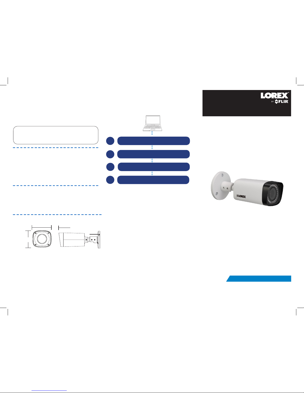
8.4”/213mm
2.8”/72mm
Dimensions
* Per camera.
3.1”/80mm
LNB3373_SERIES_TRIFOLDQSG_EN_R2
Resources
Vist www.lorextechnology.com
Search the model number of your product
Click on your product in the search results
1
2
3
4
Click the Downloads tab
Need Help?
Visit us online for up-to-date software and complete
instruction manuals
Before installing the camera:
• Decide whether to run the cables
through the wall / ceiling (drilling
required) or along the wall / ceiling.
• If you run the cables along the wall
/ ceiling, you must run the cable
through the cable notch on the base.
This will keep the camera base flush
to the wall / ceiling when mounted.
To install the camera:
1. Use the included mounting template to mark holes
for the screws. Drill holes for the mounting screws.
NOTE: Insert the included drywall anchors if you
are installing the camera in drywall.
2. Feed the cable through the mounting surface or
cable notch and mount the camera stand to the
surface using the provided screws (3x).
3. Connect cables as shown in the section “Connecting
the Camera”.
4. Set the position and angle of the camera using the
provided Allen key. Tighten the screws when
finished.
A. Loosen the screw near the camera housing. Twist
the camera to make sure the picture is level.
B. Loosen the center screw. Tilt the camera.
C. Loosen the screw near the camera base. Rotate
the camera base.
Installing the Camera
Cable Extension Options
Extend the Ethernet cable run for your camera up to 300ft. See
table below. It is recommended to use UL CMR approved cables
available at www.lorextechnology.com
Cable Type Max Cable
Run Distance
Max # of
Extensions
Cat5e or higher Ethernet
cable
300ft / 92m 3
You can use a RJ45 Coupler (not included) or switch (not included)
to connect male ends of Ethernet cable together.
ATTENTION - Ensure the camera is working correctly prior to
permanent installation by temporarily connecting the camera(s) and
cable(s) to the NVR.
Problem Solution
No picture / signal • The camera may take up to 1 minute to power
up after being connected to the NVR. Wait two
minutes before following the steps below
• Ensure the camera is connected to your NVR
or to your local network
• If you are not using PoE, you must connect
the camera to a 12V DC power adapter (not
included)
• If the camera is connected to the LAN, you
must search your network for cameras using the
NVR. See the NVR’s Instruction Manual
• Ensure your NVR is connected to a TV/monitor
• There may be an issue with your extension
cable run. Connect the camera to the NVR
using a different Ethernet cable
Picture is too bright • Ensure your camera isn’t pointed directly at a
source of light (e.g. sun or spot light)
• Move your camera to a different location
• Check the brightness and contrast settings on
the NVR
Picture is too dark • If using during the day, the camera may not be
getting enough light. Slide the sunshade (bullet
cameras featuring adjustable sunshades only)
backwards to let in more light
• Check the brightness and contrast settings on
the NVR
Night vision is not
working
• The night vision activates when light levels
drop. The area may have too much light
Picture is not clear • Check the camera lens for dirt, dust,
spiderwebs. Clean the lens with a soft, clean
cloth
• Make sure that the cable run is within the
limitations specified in the section ‘Cable
Extension Options’
Bright spot in video
when viewing camera
at night
• Night vision reflects when pointing a camera
at a window. Move the camera to a different
location
Troubleshooting
To Camera:
To NVR:
1. Connect the Ethernet cable
to the camera.
NOTE: A 12V DC power
adapter is only required if
connecting the camera’s
Ethernet cable to a router or
switch that does not support
PoE. To do this, use ACC-U41
(not included) without a
power-splitter cable.
2. Connect the other end of the
Ethernet cable to the NVR’s PoE
ports. The camera may take up to
1 minute to power up after being
connected to the NVR.
OR
Connect the other end of the Ethernet
cable to a router or switch on your
network. See the NVR Instruction
Manual for details on connecting the
camera to your NVR.
Connecting the Camera
Cable Notch
NVR
ATTENTION - This camera includes an Auto Mechanical IR Cut Filter. When
the camera changes between Day/Night viewing modes, an audible clicking
noise may be heard from the camera. This clicking is normal, and indicates
that the camera filter is working.
OR
Router or switch
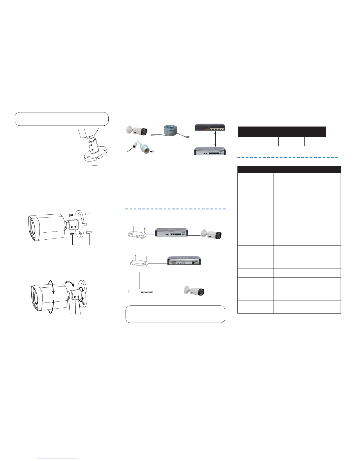
SCENARIO 1: Connect Cameras to NVR
SCENARIO 2: Connect Cameras to Local Area Network (LAN)
Router
Router
NVR
NVR
Camera
PoE Switch
Camera
Setup Diagram
Ethernet Cable
12V DC
(optional)
Mounting screws
A B C
Drywall anchors
 Loading...