

Page 1

10/100 Fast Ethernet PCI
Adapter
English
Deutsch
Italienisch
Französisch
Spanisch
Ver. 4.6
E-1
Page 2

FCC Statement
This device compiles with Part 15 of the FCC Rules.
Operation is subject to the following two conditions:
(1) This device may not cause harmful interference, and
(2) This device must accept any interference received,
including interference that may cause undesired operation.
Warning! This equipment has been tested and found to
comply with the limits for a Class B digital device, pursuant
to Part 15 of the FCC Rules. These limits are designed to
provide reasonable protection against harmful interference
when the equipment is operated in a commercial
environment. This equipment generates, uses and can
radiate radio frequency energy and, if not installed and used
in accordance with the instructions, may cause harmful
interference to radio communications. Operation of this
equipment in a residential area is likely to cause harmful
interference in which case the user will be required to
correct the interference at his own expense.
CE Declaration of conformity
This equipment complies with the requirements relating to
electromagnetic compatibility, EN 55022 class A for ITE, the
essential protection requirements of Council Directive
89/336/EEC on the approximation of the laws of the
Member States relating to electromagnetic compatibility.
Copyright © 2002, All right Reserved.
Document Version:4.6
All Trademarks and trade names are the properties of their
respective owners.
E-2
Page 3

1. Introduction
Congratulations on the purchasing of your new 10/100
NWay Fast Ethernet PCI adapter. This document describes
the Installation of network adapter. This adapter supports
10BASE-T/100BASE-TX Fast Ethernet and complies with
the electrical and protocol requirements of the PCI Local
Bus Specification, revision 2.2. The Wake-On-LAN feature
is optional for the adapter.
1.1 Features
The 10/100 Fast Ethernet PCI adapter is a cost effective,
high-performance network interface card. It operates in
10BASE-T and 100BASE-TX modes and integrates easily
with Fast Ethernet hub and switch.
y IEEE 802.3 10BASE-T and 100BASE-TX standards
y 32-bit bus master for high throughput and low CPU
utilization
y Wake-On-LAN feature is optional for different
hardware version
y Full-duplex operation at both 10Mbps and 100Mbps
y Supports 10/100Mbps auto-sensing capability
y Rich diagnostic LED mounted on bracket for easily
viewing and troubleshooting
y Single shield RJ-45 connector for using at either
Speed (Category 3, 4 or 5 UTP cable for 10Mbps
Operation, and Category 5 UTP cable for 100Mbps
Operation)
y Plug and Play Installation.
y Test program (include Wake-On-LAN events)
y Network drivers on the diskette for Windows 95, 98,
ME, NT, 2000, XP, NetWare, SCO Unix and Packet
driver.
y FCC, CE certification
1.2 System Requirements
To use the adapter, you need the following components:
y One PCI master mode expansion slot that is
compliant with PCI bus specifications, revisions 2.2
y A 3.5-inch,1.44MB diskette drive
y The following cables:
To operate at 10Mb/s, a Category 3, 4, 5 UTP Cable
To operate at 100Mb/s, a Category 5 UTP cable
E-3
Page 4

2. Installation
This section describes how to install the adapter. For
connecting to the network, you must have the following:
1. Network adapter card installed to your computer.
2. Cabling (compatible with network topology)
3. Connect the Wake-On-LAN cable to the motherboard
(If the WOL function is supported on the adapter)
4. Software for the adapter card contains both configuration
utilities and drivers
2.1 Unpack and Inspect
Caution:
Under ordinary circumstances, this adapter card will
not be affected by static charge as may be received
through your body during handling of the unit .In
special circumstances where you may carry an
extraordinarily high static charge, it had better reduce
the charge by touching a ground before handling the
adapter card.
Open the shipping gift box and carefully remove all items. In
addition to this User’s Manual, please check the following
items:
y One 10/100 Fast Ethernet PCI Adapter Card
y One WOL cable (If adapter supports WOL function)
y One 3.5” Drivers and Utilities diskette
y This user’s Manual
Note:
If any of the listed items are missing, please contact
your distributor or reseller
E-4
Page 5

2.2 Install the Adapter
1. Turn off the computer.
2. Remove the computer’s cover, in accordance to its
manual.
3. Insert the contact edge of the adapter card into the
connector of any available PCI Bus master expansion
slot. Press the card firmly into the connector to PCI slot.
Please make sure that the card’s contacts are fully
seated in the PCI slot.
4. Install the bracket screw that secures the card to the
Computer chassis.
5. Connect the WOL cable to the motherboard. (If adapter
supports WOL function)
6. Replace the computer’s cover.
7. Connect the CAT3 or CAT5 UTP cable to the RJ-45
network connector.
8. Remove [Drivers and Utilities] diskette from the PC
diskette drive.
9. Turn on the computer.
10. If the BIOS section of your computer’s boot program is
Plug and Play compliant, then at power up the BIOS will
configure any newly installed adapter automatically.
Note:
Due to some Plug-n-Play BIOS programs' problem, it
happens occasionally that a newly installed adapter is
assigned an Interrupt Number which is already used
by another device adapter. In such a case, the conflict
of Interrupt Number will cause faults in the behavior of
both devices. Then it is necessary to run the CMOS
Setup utility, and manually assign a non-conflict
Interrupt Number.
E-5
Page 6

2.3 Connect Fast Ethernet
Category 5 UTP cable is required for Fast Ethernet
operation. The maximum cable run between the adapter
and the supporting hub is 300ft (100m). Make the network
connection by plugging one end of the cable into the RJ-45
receptacle of the adapter, and the other end into one port in
the hub.
2.4 Connect 10Mbps Ethernet
Category 3, Category 4, and Category 5 UTP cable, as well
as EIA/TIA 568 100 ohm STP cable, all qualification under
Ethernet cabling rules. The maximum cable length run
between this adapter and the supporting hub is 300 ft. Make
the network connection by plugging one end of the cable
into the RJ-45 receptacle of this adapter, and the other end
into the hub.
E-6
Page 7

2.5 Drivers and Utilities Diskette
The [Divers and Utilities] diskette contains all the popular
operating system drivers.
y Novell NetWare(client /server)
y Windows NT 3.5, NT4.0/2000/XP
y Windows 95/98/ME
y Microsoft Client (NDIS 2.0 DOS/OS2)
y Windows For Workgroup 3.11
y Linux Red Hat 6.0, 6.1
y …. and so on
2.6 Software Installation
Please refer to “Quick Installation Guide”
2.7 Test Program
This test program verifies configuration of the adapter and
assists the isolation of any faults in operation. Test
procedure are optional, and will only be useful in the
unusual event that there is a fault, such as an interrupt
number conflict among your computer’s add on cards, If
your installation provides normal operation, you do not need
these test procedures.
At your DOS prompt, type the following command:
a:\rset8139.exe <Enter>
The opening screen is displayed as following:
View Current Configuration
Set Up New Configuration
Run Diagnostics
Exit RSET8139
Choose <Set Up New Configuration> item allows you to
set up the Network Speed, 10 or 100M, and Transmission
Mode, Full or Half Duplex, and so on. Choose <Run
Diagnostics> item to run the adapter test program.
Adapter test program includes:
<Run EEPROM Test>,
<Run Diagnostics on Board>,
<Run Diagnostics on Network>, and
<Run Power Management Test>.
The Power Management Test is available for WOL adapter
only.
E-7
Page 8
After choosing the <Run Diagnostics on Board> item, the
N
k
screen will display like,
ˡ˷˸ʳ˜˗ˁˁˁˁˁˁˁˁˍʳ˃˃ʳ˸˃ʳˊ˷ʳ˶˃ʳ˃˃ʳ˃˄ʳ
ˡ˸˾ʳ˦˸˸˷ˁˁˍʳ˄˃˃ˠ˵ʳ
˜˂ˢʳ˕˴˸ʳˁˁˁˁˁˁˍʳ˘˃˃˃˛ʳ
˜˸ʳˁˁˁˁˁˍʳ˄˄ʳ
˙˿˿ˀ˗˿˸ʳˁˁˁˍʳ˗˼˴˵˿˸˷ʳ
ʳ
ʳʳʳʳʳʳʳʳʳʳʳʳʳʳʳʳʳʳʳʳʳʳˣ˴ʳ˖ʳʳ˙˴˼˿ʳ˖ʳ
˔ˁʳ˜˂ˢʳ˥˸˺˼˸ʳ
˕ˁʳ ˄˃˃ˠ˵ʳ˟˵˴˶˾ʳ
˖ˁʳ ˄˃ˠ˵ʳ˟˵˴˶˾ʳ
˗ˁʳ˖˴˵˿˸ʳ˖˸˶˼ʳ
ʳ
<Cable Connection> test reminds you that the connection
link might be fail, either the cable is not connected or the
cable link fails.
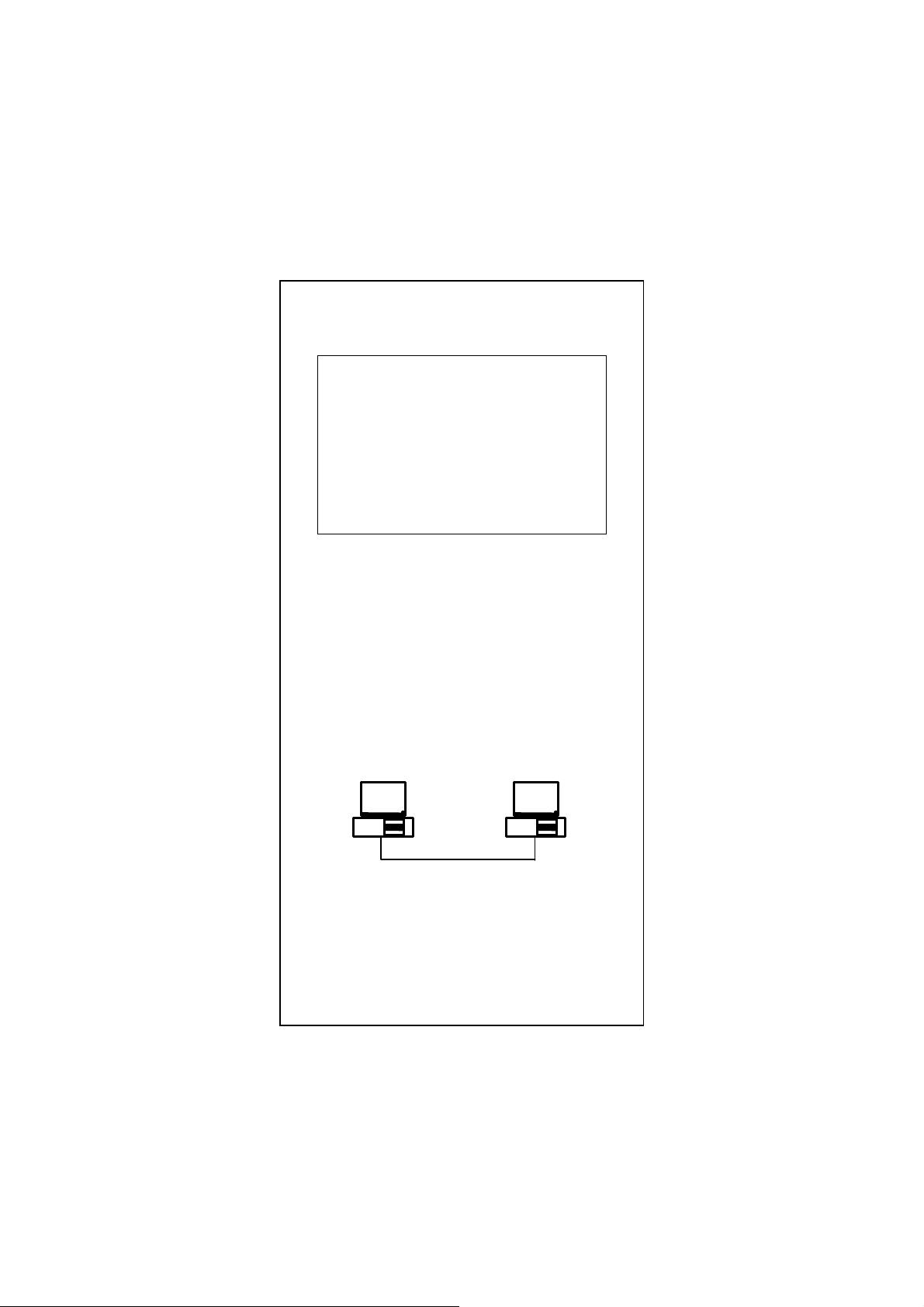
For the <Run Diagnostics on Network> test, it is
necessary to connect your computer with its supporting hub
or another computer. This is a "Ping-Pong" test. This test
cannot be completed except two computers on the LAN for
sending or receiving the test packets between computers.
For the <Run Diagnostics On Network> test
Ethernet Address
00E07DC00002
Target Machine
etwor
Master Machine: Master machine sends magic packet or
wake up frame through the network.
Target Machine: Target machine is notified whenever a
qualified wakeup packet is received.
Ethernet Address
00E07DC00001
Master Machine
E-8
Page 9

To wake up Target Machine with Magic Packet
Step1: Target Machine:
Target Machine is necessary to use the WOL cable
link the Wake On LAN connector on adapter with
your motherboard. Check BIOS <POWER
MANGEMENT SETUP> ACPI, Wake On LAN
function must be enable.
Step2: Target Machine:
Select <Target Machine> then the system will setup
wakeup event and wait a magic packet to do system
wakeup
Step3: Master Machine:
Select <Magic Packet> to send a magic packet and
wake up the target machine. The MAC address of
target machine will be asked for key-in, like
00 e0 7d c0 00 02.
Step4: Target Machine:
ACPI Testing events will be show
Device State 1: PASS
Device State 2: PASS
Device State 3: PASS
Step5: Target Machine:
Put the Target Machine to power down mode.
Step6: Master Machine:
Send a magic packet to wake up Target Machine.
Test the Wakeup Frame
Step1: Target Machine:
Select <Target Machine> then the system will setup
wakeup event and wait a magic packet to do system
wakeup
Step2: Master Machine:
Select<WakeUp Frame> to send a wakeup frame.
Step3: Target Machine :
ACPI Testing events will be show
Device State 1: PASS
Device State 2: PASS
Device State 3: PASS
Note:
Adapter testing program can not be used in Windows
95/98 DOS mode. Do not load any device drivers,
memory manager, and anti-virus software. The testing
program only can work in clean DOS prompt.
E-9
Page 10

Quick Installation Guide
Please take the following steps for driver installation.
Microsoft Windows 95/Windows 98/Windows ME
1. Turn off the computer.
2. Insert the adapter into the available PCI slot.
3. Restart the computer.
4. After Microsoft Windows reboot, the PCI Ethernet
Controller will be found.
5. The system will prompt for driver installation.
6. Insert the “Driver and Utilities” diskette into diskette driver
and press <Enter>.
7. For Windows 95, Key in a:\ path to install driver for the
adapter.
8. For Windows 98, Key in a:\w98_2000 path to install driver
for the adapter.
9. For Windows ME, Key in a:\winme path to install driver for
the adapter.
10. The Windows system will install the driver automatically.
11. Reboot the Windows system.
Windows NT
1. Turn off the computer.
2. Insert the adapter into the available PCI slot.
3. Restart the computer.
4. Click “Start” menu bar and select “Setting” item then
“Control Panel” setting
5. Select “Network” icon
6. If this is the first time to install network on the machine
then the system will ask “YES” or “NO” to install network
adapter. Please select “YES”
7. If the computer already install network before then you
need to select “Interface” -> “Add”
8. The system will prompt for driver installation.
9. Insert the “Driver and Utilities” diskette into diskette driver
and press <Enter>.
10. Key in a:\winnt path to install driver for the adapter
11. The Windows system will install the driver automatically.
12. Reboot the Windows system.
E-10
Page 11

Microsoft Windows 2000
1. Turn off the computer.
2. Insert the adapter into the available PCI slot.
3. Restart the computer.
4. After Microsoft Windows reboot, the 10/100Mbps Fast
Ethernet Adapter will be found and the system will
assign the default network driver to the adapter.
5. Select “Control Panel” from “Start” menu bar
6. Select “Network and Dial-Up Connection” folder and click
“Local Area Connection”.
7. Click “Configure” item and select “Driver”
8. From the “Driver” item then choose “Update Driver”
9. The system will prompt two optional for driver search, one
is auto search and the other is “Display a list of known
drivers ….”. Please select second one “Display …”.
10. The system will prompt for driver installation and please
select “Have Disk” button.
11. Key in a:\w98_2000 path to install driver for the adapter
Microsoft Windows XP
1. Turn off the computer.
2. Insert the adapter into the available PCI slot.
3. Restart the computer.
4. After Microsoft Windows reboot, the 10/100Mbps Fast
Ethernet Adapter will be found and the system will
assign the default network driver to the adapter.
5. Select “Control Panel” from “Start” menu bar
6. Select “Network Connection” folder then click “Local Area
Connection” and “Properties”.
7. Click “Configure” item and select “Driver”
8. From the “Driver” item then choose “Update Driver”
9. Choose “Install from a list or specific location(Advanced)”
and click “Next”.
10. Select “Don’t search, I will choose the driver to install”
then click “Next”.
11. The system will prompt for driver installation and please
select “Have Disk” button.
12. Key in a:\WinXP path to install driver for the adapter.
E-11
Page 12

Novell Netware System
Please execute the following commands:
For Netware Client
LSL
RTSODI
IPXODI
NETX or VLM
F:
LOGIN <USERNAME>
For Netware Server
LOAD RTSSRV
BIND IPX TO RTSSRV
The help file in the diskette will describe the detail driver
installation information for all popular operating systems.
E-12
Page 13

10/100 Fast Ethernet PCI
Adapter
English
Deutsch
Italienisch
Französisch
Spanisch
Ver. 4.6
D-1
Page 14

FCC Statement
This device compiles with Part 15 of the FCC Rules.
Operation is subject to the following two conditions:
(1) This device may not cause harmful interference, and
(2) This device must accept any interference received,
including interference that may cause undesired operation.
Warning! This equipment has been tested and found to
comply with the limits for a Class B digital device, pursuant
to Part 15 of the FCC Rules. These limits are designed to
provide reasonable protection against harmful interference
when the equipment is operated in a commercial
environment. This equipment generates, uses and can
radiate radio frequency energy and, if not installed and used
in accordance with the instructions, may cause harmful
interference to radio communications. Operation of this
equipment in a residential area is likely to cause harmful
interference in which case the user will be required to
correct the interference at his own expense.
CE Declaration of conformity
This equipment complies with the requirements relating to
electromagnetic compatibility, EN 55022 class A for ITE, the
essential protection requirements of Council Directive
89/336/EEC on the approximation of the laws of the
Member States relating to electromagnetic compatibility.
Copyright © 2002, All right Reserved.
Document Version:4.6
All Trademarks and trade names are the properties of their
respective owners.
D-2
Page 15

1. Einführung
Glückwunsch zu Ihrem Kauf des neuen 10/100 N-Way Fast
Ethernet PCI Adapter. Dieses Handbuch beschreibt die
Installation des Netzwerk Adapters. Dieser Adapter
unterstützt 10BASE-T/100BASE-TX Fast Ethernet und
entspricht den elektrischen und Protokoll Voraussetzungen
der PCI Local Bus Spezifikation, Revision 2.0 und 2.1. Die
Wake-On-LAN Eigenschaft ist optional für diesen Adapter.
1.1 Eigenschaften
Der 10/100 Fast Ethernet PCI Adapter ist eine günstige
hochleistungs Netzwerk Interface Karte. Sie arbeitet im
10BASE-T und 100BASE-TX Mode und arbeitet mit Fast
Ethernet Hub‘s und Switches.
y IEEE 802.3 10BASE-T und 100BASE-TX Standards
y 32-bit Bus Master für hohen Datendurchsatz und
niedriger CPU Belastung
y Wake-On-LAN Eigenschaft ist optional für
unterschiedliche Hardware Versionen.
y Full-duplex Operation für 10Mbps und 100Mbps
y Unterstützt 10/100Mbps auto-sensing
y Diagnostik LED‘s
y Geschirmte RJ-45 Buchse für(Kategorie 3, 4 oder 5
UTP Kabel für 10Mbps Operation, und Kategorie 5
UTP Kabel für 100Mbps Operation)
y Plug und Play Installation.
y Test Programm (einschließlich Wake-On-LAN )
y Netzwerk Treiber für Windows 95, 98, ME, NT, 2000,
XP, NetWare, SCO Unix und Packet Treiber.
y FCC,CE
1.2 System Voraussetzungen
Um diesem Adapter zu benutzen, benötigen Sie folgendes:
y Einen freien PCI Master Mode Steckplatz der PCI
Bus Spezifikation, Revision 2.0 und 2.1entspricht.
y Ein 3.5-inch,1.44MB Disketten Laufwerk
y Die folgenden Kabel:
Für: 10Mb/s, a Kategorie 3, 4, 5 UTP Kabel
Für: 100Mb/s, a Kategorie 5 UTP Kabel
D-3
Page 16

2. Installation
Dieser Abschnitt beschreibt die Installation des Adapters.
Für die Verbindung mit dem Netzwerk benötigen Sie
folgendes:
1. Eine Installierte Netzwerk Karte..
2. Verkabelung (Kompatible mit der Netzwerk Topologie)
3. Verbindung des Wake-On-LAN Kabels mit dem
Motherboard (Falls die WOL Funktion unterstützt wird)
4. Software für die Adapter Karte enthält Konfiguration Tools
und Treiber.
2.1 Inhalt der Packung
Achtung:
Unter normalen Umständen, wird die Karte nicht
durch Statische Aufladung geschädigt. Um statische
Aufladung und Schädigung der Karte zu vermeiden
ist es ratsam, bevor Sie die Karte berühren ein
geerdeten Anschluß zu berühren..
Die Packung sollte folgendes beinhalten:
y Eine 10/100 Fast Ethernet PCI Adapter Karte
y Ein WOL Kabel Falls Karte WOL unterstützt)
y Eine 3.5” Treiber und Utilities Diskette
y Dieses Handbuch
Notiz:
Falls eines der aufgelisteten Teile fehlt setzten Sie
sich bitte mit Ihrem Händler in Verbindung.
D-4
Page 17

2.2 Installation des Adapters
1. Schalten Sie den Computer aus.
2. Entfernen Sie das Gehäuse, wie in Ihrem Computer
Handbuch beschrieben.
3. Stecken Sie die Kontaktleiste in einen freien PCI
Steckplatz. Drücken Sie die Karte vorsichtig in den PCI
Steckplatz. Versichern Sie sich das die Karte einen
guten Kontakt mit dem Steckplatz hat.
4. Befestigen Sie die Karte mit der Schraube am Computer
Gehäuse.
5. Verbinden Sie das WOL Kabel mit dem Motherboard.
(Falls der Adapter WOL unterstützt)
6. Schliessen Sie das Computer Gehäuse.
7. Verbinden Sie das CAT3 oder CAT5 UTP Kabel mit der
RJ-45 Buchse der Karte.
8. Entfernen Sie [Treibers und Utilities] Diskette aus dem
PC Disketten Laufwerk.
9. Schalten Sie den Computer ein.
10. Falls die BIOS Sektion Ihres Computers Start
Programmes Plug und Play fähig ist, wird der Adapter
während des Startvorganges automatisch Konfiguriert.
Notiz:
Einige Plug-n-Play BIOS Programme können
Probleme haben und verschiede Geräten gleiche
Interrupts zuordnen. In diesem Fall kann es dazu
führen das die Geräte nicht funktionieren. Dann
müssen Sie das CMOS Setup per Hand einstellen.
D-5
Page 18

2.3 Verbindung Fast Ethernet
Kategorie 5 UTP Kabel ist vorgeschrieben für Fast Ethernet
Operation. Die maximale Kabellänge zwischen dem
Adapter und einem Hub ist 300ft (100m). Stecken Sie das
Netzwerkkabel in die Buchse des Adapters und das andere
Ende in einen Anschluß des Hubs.
2.4 Verbindung 10Mbps Ethernet
Kategorie 3, Kategorie 4, und Kategorie 5 UTP Kabel, sowie
EIA/TIA 568 100 Ohm STP Kabel, Die maximale
Kabellänge zwischen dem Adapter und einem Hub ist 300ft
(100m). Stecken Sie das Netzwerkkabel in die Buchse des
Adapters und das andere Ende in einen Anschluß des
Hubs.
D-6
Page 19

2.5 Treibers und Utilities Diskette
Die [Divers und Utilities] Diskette enthält alle Treiber für
die populären Betriebssysteme.
y Novell NetWare (Client /Server)
y Windows NT 3.5 , NT4.0 / 2000 / XP
y Windows 95/98/ME
y Microsoft Client (NDIST 2.0 DOS/OS2)
y Windows For Workgroup 3.11
y Linux
y …. und so weiter
2.6 Software Installation
Bitte sehen Sie unter „Kurzanleitung“ nach.
2.7 Test Programm
Diese Test Programm überprüft die Konfiguration des
Adapters und zeigt mögliche Fehlerquellen auf. Dieser Test
ist optional bei Fehlfunktionen, wie gleiche Interrupt
Nummer mit anderen Karte in Ihrem Computer. Falls die
Installation normal funktioniert, benötigen Sie dieses
Testprogramm nicht.
An der DOS Eingabeaufforderung tippen Sie bitte:
a:\rset8139.exe <Enter>
Der Bildschirm zeigt folgendes:
View Current Configuration
Set Up New Configuration
Run Diagnostics
Exit RSET8139
<Set Up New Configuration> erlaubt Ihnen die Einstellung
der Netzwerk Geschwindigkeit, 10 oder 100M, und
Transmissions Modus, Full oder Half Duplex, und so weiter.
<Run Diagnostics> Startet das Adapter Test Programm.
Das Adapter Test Programm beinhaltet:
<EEPROM Test>,
<Run Diagnostics on Board>,
<Run Diagnostics on Network>, und
<Run Power Management Test>.
Der Power Management Test ist nur für WOL Adapter.
D-7
Page 20

Wenn Sie <Run Diagnostics on Board> wählen ,
N
k
erscheint folgender ähnlicher Bildschirm,
ˡ˷˸ʳ˜˗ˁˁˁˁˁˁˁˁˍʳ˃˃ʳ˸˃ʳˊ˷ʳ˶˃ʳ˃˃ʳ˃˄ʳ
ˡ˸˾ʳ˦˸˸˷ˁˁˍʳ˄˃˃ˠ˵ʳ
˜˂ˢʳ˕˴˸ʳˁˁˁˁˁˁˍʳ˘˃˃˃˛ʳ
˜˸ʳˁˁˁˁˁˍʳ˄˄ʳ
˙˿˿ˀ˗˿˸ʳˁˁˁˍʳ˗˼˴˵˿˸˷ʳ
ʳ
ʳʳʳʳʳʳʳʳʳʳʳʳʳʳʳʳʳʳʳʳʳʳˣ˴ʳ˖ʳʳ˙˴˼˿ʳ˖ʳ
˔ˁ˜˂ˢʳ˥˸˺˼˸ʳ
˕ˁ˄˃˃ˠ˵ʳ˟˵˴˶˾ʳ
˖ˁ˄˃ˠ˵ʳ˟˵˴˶˾ʳ
˗ˁ˖˴˵˿˸ʳ˖˸˶˼ʳ
ʳ
<Cable Connection> Test zeigt Ihnen ob die
Kabelverbindung in Ordnung ist.
Für den <Run Diagnostics on Network> Test, ist es
notwendig eine Verbindung Ihres Computers mit einem
anderen Computer zu haben. Dies ist ein "Ping-Pong" Test.
Dieser Test kann nur beendet werden mit Senden und
Empfangen von Datenpaketen zwischen zwei Computern.
Der <Run Diagnostics On Network> Te s t
Ethernet Address
00E07DC00002
Target Machine
etzwer
Master PC: Master PC sendet ein „magic packet“ oder ein
„Wake up frame“ durch das Netzwerk.
Ziel PC: Der Ziel PC erkennt wenn immer ein qualifiziertes
Paket empfangen wird.
Ethernet Address
00E07DC00001
Master Machine
D-8
Page 21

Starten des Ziel PCs mit einem „Magic Packet“
Step1: Ziel PC:
Beim Ziel PC mus das WOL Kabel der Karte mit dem
Motherboard verbunden sein. Prüfen Sie im BIOS
<POWER MANGEMENT SETUP> ACPI, Wake On
LAN Funktion muß Eingeschaltet sein.
Step2: Ziel PC:
Wählen Sie <Target Machine> Dann wartet das
System auf ein „magic packet“ um selbständig zu
starten.
Step3: Master PC:
Wählen Sie <Magic Packet> um ein „magic
packet“ zu senden und den Ziel PC zu starten. Es
wird nach der MAC Adresse des Ziel PCs gefragt
geben Sie die Adresse ein wie z. Bsp.
00 e0 7d c0 00 02 ein.
Step4: Ziel PC:
ACPI Test Ergebnis soll zeigen
Device State 1: PASS
Device State 2: PASS
Device State 3: PASS
Step5: Ziel PC:
Fahren Sie den Ziel PC herunter.
Step6: Master PC:
Sendet ein „magic packet“ um den Ziel PC zu starten.
Testen des „Wakeup Frame“
Step1: Ziel PC:
Wählen Sie <Target Machine> Dann wartet das
System auf ein „magic packet“ um selbständig zu
starten.
Step2: Master PC:
Wählen Sie <WakeUp Frame> um eben diesen zu
senden.
Step3: Ziel PC :
ACPI Test Ergebnis soll zeigen.
Device State 1: PASS
Device State 2: PASS
Device State 3: PASS
Notiz:
Das Adapter Testprogramm funktioniert nicht unter
Windows 95/98 DOS Modus. Laden Sie keine Treiber,
Speicher Manager oder Virus Scanner. Dieses
Programm arbeitet nur am reinen DOS Prompt.
D-9
Page 22

Kurzanleitung
Bitte folgen Sie den Schritten für die Treiber Installation
Microsoft Windows 95 / Windows 98 / Windows ME
1. Schalten Sie den Computer aus.
2. Stecken Sie den Adapter in einen freien PCI Steckplatz
3. Starten Sie den Computer
4. Nach dem Start wird der Adapter von Microsoft
Windows erkannt.
5. Das System fordert Sie zur Treiber Installation auf.
6. Stecken Sie die “Treiber und Utilities” Diskette in das
Disketten Laufwerk und Drücken Sie <Enter>.
7. Für Windows 95, geben Sie bitte a:\ Pfad für die
Installation ein.
8. Für Windows 98, geben Sie bitte a:\w98_2000 als
Pfad für die Installation ein.
9. Für Windows ME, geben Sie bitte a:\winme als
Pfad für die Installation ein.
10. Das Windows System wird den Treiber automatisch
installieren.
11. Starten Sie Windows erneut.
Microsoft Windows NT
1. Schalten Sie den Computer aus.
2. Stecken Sie den Adapter in einen freien PCI Steckplatz
3. Starten Sie den Computer
4. Klicken Sie auf START, dann EINSTELLUNGEN dann
auf SYSTEMSTEUERUNG.
5. Wählen Sie NETZWERK
6. Bei der erst Installation von einem Netzwerk wird Sie
das System auffordern mit JA oder NEIN zu antworten,
Wählen Sie JA.
7. Bei bereits Installierten Netzwerk, Wählen Sie Blatt
NETZWERKKARTE und dort HINZUFÜGEN.
8. Das System fordert Sie zur Treiber Installation auf.
9. Stecken Sie die “Treiber und Utilities” Diskette in das
Disketten Laufwerk und Drücken Sie <Enter>.
10. Geben Sie bitte den a:\winnt Pfad für die
Installation ein.
11. Das Windows System wird den Treiber automatisch
installieren.
12. Starten Sie Windows erneut.
D-10
Page 23

Microsoft Windows 2000
1. Schalten Sie den Computer aus.
2. Stecken Sie den Adapter in einen freien PCI Steckplatz
3. Starten Sie den Computer
4. Nachdem Microsoft Windows gestartet ist, wird der
Adapter erkannt und der Standard Treiber installiert.
5. Wählen Sie EINSTELLUNGEN vom START Menü.
6. Wählen Sie NETZWERK UND DFÜ-VERBINDUNGEN
und klicken Sie auf LAN VERBINDUNGEN.
7. Klicken Sie auf KONFIGURIEREN und wählen Sie
TREIBER.
8. Das System bietet Ihnen nun zwei Optionen an, bitte
wählen Sie ZEIGE EINE LISTE....
9. Das System fordert Sie zur Treiber Installation auf,
wählen Sie DISKETTE.
10. Geben Sie bitte den a:\w98_2000 Pfad für die
Installation ein.
Microsoft Windows XP
1. Schalten Sie den Computer aus.
2. Stecken Sie die Karte in einen freien PCI Steckplatz.
3. Starten Sie den Computer neu.
4. Nach dem Neustart wird die Karte automatisch von
Windows gefunden und der Standard Treiber wird auf
die Karte gebunden.
5. Wählen Sie "Einstellungen" im "Start" Menü.
6. Wählen Sie "Netzwerkverbindungen" und klicken auf
"LAN-Verbindung" und dort auf "Eigenschaften”.
7. Klicken Sie auf "Konfigurieren" und wählen Sie "Treiber"
aus.
8. Auf dem "Treiber" Blatt wählen Sie "Aktualisieren".
9. Wählern Sie “Software von einer Liste....
(Fortgeschrittene)" und dann auf "Weiter".
10. Wählen Sie "Nicht suchen, sonder…" und klicken auf
"Weiter".
11. Das System fragt Sie nach der Treiberdatei, klicken Sie
auf "Datenträger".
12. Geben Sie den Pfad a:\WinXP für die Installation an,
und klicken auf "OK".
D-11
Page 24

Novell Netware System
Bitte führen Sie folgende Eingaben durch:
Für Netware Client
LSL
RTSODI
IPXODI
NETX oder VLM
F:
LOGIN <USERNAME>
Für Netware Server
LOAD RTSSRV
BIND IPX TO RTSSRV
Die Hilfe Datei auf der Diskette enthält nähere Erklärungen.
(In Englisch)
D-12
Page 25

Scheda
Fast Ethernet 10/100 PCI
English
Deutsch
Italienisch
Französisch
Spanisch
Ver. 4.6
I-1
Page 26

FCC Statement
This device compiles with Part 15 of the FCC Rules.
Operation is subject to the following two conditions:
(1) This device may not cause harmful interference, and
(2) This device must accept any interference received,
including interference that may cause undesired operation.
Warning! This equipment has been tested and found to
comply with the limits for a Class B digital device, pursuant
to Part 15 of the FCC Rules. These limits are designed to
provide reasonable protection against harmful interference
when the equipment is operated in a commercial
environment. This equipment generates, uses and can
radiate radio frequency energy and, if not installed and used
in accordance with the instructions, may cause harmful
interference to radio communications. Operation of this
equipment in a residential area is likely to cause harmful
interference in which case the user will be required to
correct the interference at his own expense.
CE Declaration of conformity
This equipment complies with the requirements relating to
electromagnetic compatibility, EN 55022 class A for ITE, the
essential protection requirements of Council Directive
89/336/EEC on the approximation of the laws of the
Member States relating to electromagnetic compatibility.
Copyright © 2002, All right Reserved.
Document Version:4.6
All Trademarks and trade names are the properties of their
respective owners.
I-2
Page 27

1. Introduzione
Congratulazioni per l’acquisto della scheda Fast Ethernet
10/100 NWay PCI. Questo documento descrive
l’installazione della scheda di rete. Questo adattatore
supporta Fast Ethernet 10BASE-T/100BASE-TX ed è
conforme ai requisiti elettrici e di protocollo delle Specifiche
PCI Local Bus, revisione 2.2. Su questa scheda la
caratteristica Wake-On-LAN è opzionale.
1.1 Caratteristiche
La scheda Fast Ethernet 10/100 PCI è un’interfaccia di rete
ad elevate prestazioni ed economica. Funziona nelle
modalità 10BASE-T e 100BASE-TX e si integra facilmente
con hub e switch Fast Ethernet.
y Standard IEEE 802.3 10BASE-T e 100BASE-TX
y Bus mastering a 32-bit per alta velocità e utilizzo
ridotto della CPU
y Funzione Wake-On-LAN opzionale per versioni
hardware differenti
y Funzionamento Full-Duplex sia a 10Mbps che a
100Mbps
y Supporto della capacità di autovilevamento
10/100Mbps
y LED di diagnosi sul supporto per migliorare la visibilità
e la soluzione dei problemi
y Connettore blindato RJ-45 utilizzabile ad entrambe le
velocità (cavo UTP di categoria 3, 4 o 5 per 10Mbps, e
cavo UTP di categoria 5 per 100Mbps)
y Installazione “Plug and Play”.
y Programma di test (include eventi Wake-On-LAN)
y Floppy con driver di rete per Windows95, 98, ME, NT,
2000, XP, NetWare, SCO Unix e Packet Driver.
y Certificazione FCC,CE
1.2 Requisiti di sistema
Per usare questa scheda, servono i seguenti componenti:
y Uno slot di espansione in modalità PCI master
conforme alle specifiche sul bus PCI, revisione 2.2
y Un’unità da 3.5”, 1.44MB
y I seguenti cavi:
Per funzionare a 10Mb/s, un cavo UTP categoria 3, 4, 5
Per funzionare a 100Mb/s, un cavo UTP categoria 5
I-3
Page 28

2. Installazione
Questa sezione descrive la procedura d’installazione della
scheda. Per collegarsi a una rete, è necessario quanto
segue:
1. Scheda di rete installata nel computer.
2. Cablaggio (compatibile con la topologia della rete)
3. Collegare il cavo Wake-On-LAN alla scheda madre (se la
funzione WOL è supportata dalla scheda)
4. Software della scheda che contiene sia le utility di
configurazione che i driver
2.1 Disimballaggio e ispezione
Precauzione:
In circostanze normali la scheda di rete non soffrirà
conseguenze negative a causa dell’elettricità statica
presente nel corpo umano. In circostanze specifiche,
qualora il tasso di elettricità statica sia elevato, si
consiglia di scaricarla toccando una superficie a
massa prima di maneggiare la scheda.
Aprire la confezione ed estrarre con precauzione tutti gli
elementi. Verificare la presenza dei seguenti elementi:
y Una scheda Fast Ethernet 10/100 PCI
y Un cavo WOL (se la scheda supporta la funzione
WOL)
y Un dischetto da 3.5” con driver e utility
y Questo manuale d’uso
Nota:
Qualora la confezione sia incompleta, rivolgersi al
distributore o al rivenditore
I-4
Page 29

2.2 Installazione della scheda
1. Spegnere il computer.
2. Aprire il computer così come descritto nel manuale dello
stesso.
3. Inserire il connettore a pettine della scheda in uno slot
d’espansione bus master PCI disponibile. Premere
saldamente la scheda nello slot PCI. Accertarsi che i
contatti della scheda siano perfettamente inseriti nello
slot PCI.
4. Installare la vite che fissa il supporto della scheda al
telaio del computer.
5. Collegare il cavo WOL alla scheda madre (se la scheda
di rete supporta la funzione WOL)
6. Richiudere il computer.
7. Collegare il cavo UTP CAT3 o CAT5 al connettore di rete
RJ-45.
8. Estrarre il dischetto [Driver e Utility] dall’unità a dischetti
del computer.
9. Accendere il computer.
10. Se il BIOS del computer è conforme allo standard Plug
and Play, all’avvio configurerà automaticamente la
nuova scheda installata.
Nota:
A causa di problemi con il plug and play di alcuni
programmi BIOS, a volte alla nuova scheda installata
viene assegnato un interrupt già usato da un’altra
scheda. In tal caso, il conflitto di interrupt provocherà
errori in entrambi i dispositivi. Sarà quindi necessario
eseguire l’utility di setup CMOS ed assegnare
manualmente un numero d’interrupt libero.
I-5
Page 30

2.3 Collegamento a Fast Ethernet
Per un utilizzo di tipo Fast Ethernet è richiesto un cavo UTP
categoria 5. La lunghezza massima del cavo tra la scheda e
lo hub di supporto è di 300 ft (100 m). Realizzare la
connessione di rete inserendo un’estremità del cavo nella
presa RJ-45 della scheda e l’altra estremità in una porta
dello hub.
2.4 Collegamento a Ethernet 10Mbps
Usare una cavo UTP categoria 3, categoria 4 o categoria 5
oppure un cavo STP EIA/TIA 568 da 100 ohm, conformi alle
norme di cablaggio Ethernet. La lunghezza massima del
cavo tra la scheda e lo hub di supporto è di 300 ft (100 m).
Realizzare la connessione di rete inserendo un’estremità
del cavo nella presa RJ-45 della scheda e l’altra estremità
nello hub.
I-6
Page 31

2.5 Dischetto con driver e utility
Il dischetto [Driver e Utility] contiene i driver per tutti i più
comuni sistemi operativi.
y Novell NetWare(client /server)
y Windows NT 3.5, NT4.0 / 2000 / XP
y Windows 95/98/ME
y Microsoft Client (NDIS 2.0 DOS/OS2)
y Windows per Workgroup 3.11
y Linux Red Hat 6.0, 6.1
y …. e così via
2.6 Installazione del software
Consultare la “Guida rapida di installazione”
2.7 Programma di test
Questo programma di test verifica la configurazione della
scheda e agevola l’isolamento di eventuali problemi di
funzionamento. Le procedure di test sono opzionali e
serviranno solo nella remota eventualità che ci sia qualche
problema, come un conflitto d’interrupt tra le varie schede
d’espansione del computer. Quindi se la scheda installata
funziona correttamente è inutile svolgere le procedure di test.
Al prompt di DOS, digitare il seguente comando:
a:\rset8139.exe <Invio>
La schermata iniziale visualizzerà quanto segue:
View Current Configuration
Set Up New Configuration
Run Diagnostics
Exit RSET8139
Scegliendo <Set Up New Configuration> si potrà
configurare la velocità della rete, 10 o 100Mbps, la modalità
di trasmissione, Full o Half Duplex, e così via. Scegliendo
<Run Diagnostics> si avvierà il programma di test della
scheda.
Il programma di test della scheda comprende:
<Run EEPROM Test> (esegui test EEPROM),
<Run Diagnostics on Board> (esegui diagnosi della scheda),
<Run Diagnostics on Network> (esegui diagnosi di rete) e
<Run Power Management Test> (esegui test di risparmio energia).
Il test di risparmio energia è disponibile solo per la scheda WOL.
I-7
Page 32

Dopo aver scelto <Run Diagnostics on Board>, apparirà
r
una schermata simile alla seguente,
Node ID........: 00 e0 7d c0 00 01
Network Speed..: 100Mbps
I/O Base ......: E000H
Interrupt .....: 11
Full-Duplex ...: Disabled
Pass Count Fail
Count
A.I/O Register
B.100Mbps Loopback
C.10Mbps Loopback
D.Cable Connection
Il test <Cable Connection> rammenta che la connessione
potrebbe fallire perché il cavo non è collegato oppure
perché il collegamento è difettoso.
Per il test <Run Diagnostics on Network>, è necessario
collegare il computer allo hub di supporto o a un altro
computer. Si tratta di un test "Ping-Pong". Il test richiede che
due computer collegati mediante LAN inviino e ricevano
pacchetti di prova.
Per il test <Run Diagnostics On Network> valgono le
seguenti impostazioni:
Indirizzo Ethernet
00E07DC00002
Macchina targe
Macchina master : La macchina master invia un Magic
Macchina target : La macchina target viene avvisata ogni volta
t
Packet o un Wake up Frame attraverso
la rete.
che riceve un pacchetto di risveglio
Indirizzo Ethernet
00E07DC00001
Macchina maste
Rete
a
I-8
Page 33

Per risvegliare una macchina target con Magic Packet
g
Fase 1: Macchina target:
La macchina target deve usare il cavo WOL di
collegamento tra il connettore Wake On LAN della
scheda di rete e la scheda madre. Controllare che
nel <POWER MANAGEMENT SETUP> del BIOS
ACPI sia abilitata la funzione Wake On LAN.
Fase 2: Macchina target:
Selezionare <Target Machine>; il sistema
predisporrà un evento di risveglio ed attenderà che
un Magic Packet risvegli il sistema
Fase 3: Macchina master:
Selezionare <Magic Packet> per inviare un Magic
Packet e risvegliare la macchina target. Verrà
richiesta l’introduzione dell’indirizzo MAC della
macchina target, ad esempio 00 e0 7d c0 00 02.
Fase 4: Macchina target:
Verranno visualizzati gli eventi di test ACPI
Fase 5: Macchina target:
Mettere la macchina target in modalità di
spegnimento.
Fase 6: Macchina master:
Inviare un Magic Packet per risvegliare la macchina
target.
Testare la Wakeup Frame
Fase 1: Macchina target : Selezionare <Target Machine>; il
Fase 2: Macchina master : Selezionare <WakeUp Frame> per
Fase 3: Macchina target:
Verranno visualizzati gli eventi di test ACPI
Nota:
Non si può usare il programma di test della scheda in
modalità DOS di Windows 95/98. Non caricare nessun
driver,
distanza.
Device State 1: PASS
Device State 2: PASS
Device State 3: PASS
sistema predisporrà un evento di risveglio
ed attenderà che un Magic Packet
risvegli il sistema
inviare una trama di risveglio
Device State 1: PASS
Device State 2: PASS
Device State 3: PASS
estore di memoria o software antivirus. Il
.
I-9
Page 34

programma di test funziona solo dal prompt di DOS.
Guida rapida d’installazione
Per l’installazione dei driver seguire i passi descritti a
continuazione.
Microsoft Windows 95/Windows 98/Windows ME
1. Spegnere il computer.
2. Inserire la scheda in uno slot PCI disponibile.
3. Riavviare il computer.
4. Una volta avviato Microsoft Windows, verrà riconosciuta
una Controller Ethernet PCI.
5. Il sistema richiederà l’installazione dei driver.
6. Inserire il dischetto “Driver e Utility” nell’unità da 3.5” e
premere <Invio>.
7. In Windows 95, digitare il percorso a:\ per installare i
driver della scheda
8. In Windows 98, digitare il percorso a:\w98_2000 per
installare i driver della scheda
9. In Windows ME, digitare il percorso a:\winme per
installare i driver della scheda
10. Windows installerà automaticamente i driver.
11. Riavviare Windows.
Windows NT
1. Spegnere il computer.
2. Inserire la scheda in uno slot PCI disponibile.
3. Riavviare il computer.
4. Fare clic su “Avvio”, scegliere “Configurazione” e quindi
“Pannello di controllo”
5. Selezionare l’icona “Rete”
6. Se è la prima volta che si installa una rete sul computer, il
sistema richiederà di rispondere “SÌ” o “NO”
all’installazione della scheda di rete. Selezionare “SÌ”
7. Se sul computer è già installata una rete, selezionare
“Interfaccia” -> “Aggiungi”
8. Il sistema richiederà l’installazione dei driver.
9. Inserire il dischetto “Driver e Utility” nell’unità da 3.5” e
premere <Invio>.
10. Digitare il percorso a:\winnt per installare i driver della
scheda
11. Windows installerà automaticamente i driver.
12. Riavviare Windows.
I-10
Page 35

Microsoft Windows 2000
1. Spegnere il computer.
2. Inserire la scheda in uno slot PCI disponibile.
3. Riavviare il computer.
4. Dopo l’avvio di Windows, verrà riconosciuta la Scheda
Fast Ethernet 10/100Mbps e il sistema le assegnerà un
driver di rete predeterminato.
5. Selezionare “Avvio”, “Pannello di controllo”
6. Selezionare la cartella “Connessione di rete e di accesso
remoto” e fare clic su “Connessione di area locale”.
7. Fare clic su “Configura” e selezionare “Driver”.
8. In “Driver” scegliere “Aggiorna driver”
9. Il sistema presenterà due opzioni di ricerca dei driver, una
è automatica e l’altra è “Visualizza elenco di driver
conosciuti ….”. Scegliere la seconda (“Visualizza …”).
10. Il sistema richiederà l’installazione dei driver;
selezionare il pulsante “Disco driver”.
11. Digitare il percorso a:\w98_2000 per installare i driver
della scheda
Microsoft Windows XP
1. Spegnere il computer.
2. Inserire la scheda in uno slot PCI libero.
3. Riavviare il Computer.
4. Dopo il reboot di Microsoft Windows, La scheda
10/100Mbps Fast Ethernet viene rilevata e il sistema
assegna di default un driver di rete alla scheda.
5. Selezionare “Control Panel” dalla barra di menu “Start”
6. Selezionare la cartella “Network Connection” e cliccare
“Local Area Connection” e “Properties”.
7. Cliccare l’opzione “Configure” e selezionare “Driver”
8. Dal opzione “Driver” selezionare “Update Driver”
9. Selezionare “Install from a list or specific
location(Advanced)” e cliccare “Next”.
10. Selezionare “Don’t search, I will choose the driver to
install” e cliccare “Next”.
11. Il sistema chiederà il Driver di installazione selezionare
“Have Disk”
12. Il percorso per l’installazione del Driver della periferica è
a:\WinXP
I-11
Page 36

Novell Netware System
Eseguire i seguenti comandi:
Per Client Netware
LSL
RTSODI
IPXODI
NETX o VLM
F:
LOGIN <NOME_UTENTE>
Per Server Netware
LOAD RTSSRV
BIND IPX TO RTSSRV
Il file Help del dischetto descriverà le informazioni
dettagliate di installazione dei driver per i sistemi operativi
più comuni.
I-12
Page 37

Adaptateur PCI 10/100 Fast
Ethernet
English
Deutsch
Italienisch
Französisch
Spanisch
Version 4.6
F-1
Page 38

FCC Statement
This device compiles with Part 15 of the FCC Rules.
Operation is subject to the following two conditions:
(1) This device may not cause harmful interference, and
(2) This device must accept any interference received,
including interference that may cause undesired operation.
Warning! This equipment has been tested and found to
comply with the limits for a Class B digital device, pursuant
to Part 15 of the FCC Rules. These limits are designed to
provide reasonable protection against harmful interference
when the equipment is operated in a commercial
environment. This equipment generates, uses and can
radiate radio frequency energy and, if not installed and used
in accordance with the instructions, may cause harmful
interference to radio communications. Operation of this
equipment in a residential area is likely to cause harmful
interference in which case the user will be required to
correct the interference at his own expense.
CE Declaration of conformity
This equipment complies with the requirements relating to
electromagnetic compatibility, EN 55022 class A for ITE, the
essential protection requirements of Council Directive
89/336/EEC on the approximation of the laws of the
Member States relating to electromagnetic compatibility.
Copyright © 2002, All right Reserved.
Document Version:4.6
All Trademarks and trade names are the properties of their
respective owners.
F-2
Page 39

1. Introduction
Nous vous remercions d’avoir choisi le nouvel adaptateur
PCI 10/100 NWay Fast Ethernet. Ce mode d’emploi décrit
comment installer l’adaptateur de réseau. Cet adaptateur
supporte 10BASE-T/100BASE-TX Fast Ethernet et suit les
exigences électriques et de protocole requises par les
spécifications du bus local PCI, révision 2.2. Le
Wake-on-LAN (WOL) est une caractéristique optionnelle de
cet adaptateur.
1.1 Caractéristiques
L’adaptateur PCI Fast Ethernet 10/100 est une carte de
réseau interface rentable et de haute performance. Il
fonctionne sous les modes 10BASE-T et 100BASE-TX et
s’intègre facilement à un hub et un switch Fast Ethernet.
y Spécifications 10BASE-T et 100BASE-TX des
normes IEEE 802.3
y Bus de maîtrise 32-bits pour haut débit et faible
utilisation du CPU
y Le Wake-on-LAN est optionnel pour des versions
différentes
y Fonctionnement full duplex à 10Mbps et 100Mbps
y Détient une capacité d’auto-détection de 10/100Mbps
y Indicateurs LED de diagnostique avancé montés sur
support pour pouvoir facilement consulter et détecter
tout problème.
y Prise blindée simple RJ-45 pour utilisation des deux
vitesses (Câble UTP de catégorie 3, 4 ou 5 pour
10Mbps , et câble UTP de catégorie 5 pour 100Mbps)
y Installation Plug and play.
y Logiciel de test (y compris des activités du Wake-on-
LAN)
y Pilote de réseau sur disquette pour Windows 95, 98,
ME, NT, 2000, XP, Netware, SCO Unix et Packet
driver.
y FCC, certification CE
1.2 Exigences du système
Pour utiliser cet adaptateur, il vous faut les composants
suivants :
y Un slot d’extension pour mode de maîtrise PCI en
accord avec les spécifications bus PCI, révision 2.2
F-3
Page 40

y Un lecteur de disquette 3,5”, 1,44 MB
y Les câbles suivants:
Pour un fonctionnement à 10Mbps, un câble UTP de
catégorie 3, 4 ou 5
Pour un fonctionnement à 100Mbps, un câble UTP
de catégorie 5
2. Installation
Dans cette section, nous décrirons comment installer
l’adaptateur. Afin de pouvoir vous connecter au réseau,
vous devez avoir :
1. Une carte de réseau installée dans votre ordinateur.
2. Les câbles nécessaires (compatibles avec la topologie du
réseau)
3. Le câble du Wake-on-LAN raccordé à la carte mère (si
l’adaptateur accepte la fonction WOL)
4. Le logiciel de la carte de réseau contenant les utilitaires
de configuration et le pilote
2.1 Déballage et inspection
Attention :
Dans des circonstances normales, cette carte de
réseau ne devrait pas se trouver affectée par les
charges d’électricité statique que vous pourriez
recevoir lors de la manipulation de l’unité centrale de
votre ordinateur. Cependant, dans certaines
circonstances particulières où il se pourrait que vous
soyez sujet à une décharge d’électricité statique
exceptionnellement forte, nous vous recommandons
de réduire l’effet de cette décharge en touchant la
terre avant de manipuler la carte.
Ouvrez la boîte d’emballage et sortez son contenu avec
précaution. En plus de ce mode d’emploi, vous devriez
trouver les articles suivants :
y Une carte de réseau PCI 10/100 Fast Ethernet
y Un câble WOL (Si l’adaptateur accepte la fonction
WOL)
y Une disquette de 3,5” avec logiciel utilitaire et pilote
y Ce mode d’emploi
F-4
Page 41

Note :
S’il manquait un des articles de la liste ci-dessus,
veuillez prendre contact avec votre distributeur ou
revendeur.
2.2 Installation de l’adaptateur
1. Eteignez l’ordinateur.
2. Enlevez le couvercle de protection, comme indiqué sur le
mode d’emploi de l’appareil.
3. Insérez l’extrémité requise de votre carte de réseau dans
la prise de n’importe quel slot d’extension disponible du
bus de maîtrise PCI. Enfoncez fermement votre carte
dans la prise du slot PCI. Assurez-vous que tous les
points de contact de la carte soient bien imbriqués dans
le slot PCI.
4. Replacez la vis du support afin de fixer définitivement la
carte sur la base de votre ordinateur.
5. Raccordez le câble WOL à la carte mère (Si votre
adaptateur accepte la fonction WOL)
6. Replacez le couvercle de l’ordinateur.
7. Raccordez les câbles UTP CAT3 ou CAT5 à la prise de
réseau RJ-45
8. Enlevez la disquette [pilote et utilitaire] du lecteur de
disquette de votre ordinateur.
9. Mettez l’ordinateur en marche.
10. Si la section BIOS du logiciel de démarrage de votre
ordinateur accepte le système Plug and play, celui-ci
configurera tout adaptateur récemment installé
automatiquement dès la mise en marche.
Note :
Dû à des problèmes rencontrés dans certains logiciels
Plug and play BIOS, il se peut qu’occasionnellement
un numéro IRQ déjà utilisé par un autre module soit
assigné à l’adaptateur récemment installé. Dans ce
cas, le numéro IRQ en question causera des erreurs
de fonctionnement des deux modules. Il faut donc
absolument mettre en marche l’utilitaire d’installation
CMOS, et ré-assigner manuellement un numéro IRQ
ne prêtant pas à conflits.
F-5
Page 42

2.3 Connexion au Fast Ethernet
Pour le Fast Ethernet, il faut un câble UTP de catégorie 5.
La longueur du câble maximum entre l’adaptateur et le hub
lui correspondant est de 100 mètres. Connectez le réseau
en branchant l’une des extrémités du câble dans la prise
RJ-45 de l’adaptateur, et l’autre extrémité dans l’un des
ports du hub.
2.4 Connexion Ethernet 10Mbps
Câbles UTP de catégorie 3, 4 et 5, ainsi que des câbles STP
EIA/TIA 568 de 100 ohms, tous en accord avec les
réglementations du câblage Ethernet. La longueur de câble
maximum entre cet adaptateur et le hub lui correspondant
est de 100m. Raccordez le réseau en branchant l’une des
extrémités du câble dans la prise RJ-45 de cet adaptateur,
et l’autre extrémité dans le hub.
F-6
Page 43

2.5 Disquette pilote et utilitaire
La disquette [pilote et utilitaire] contient le pilote
correspondant aux systèmes les plus courants.
y Novell NetWare(client /server)
y Windows NT 3.5 , NT4.0 / 2000 / XP
y Windows 95/98/ME
y Microsoft Client (NDIS 2.0 DOS/OS2)
y Windows For Workgroup 3.11
y Linux Red Hat 6.0, 6.1
y …. etc
2.6 Installation du logiciel
Prière de vous référer au « Guide d’installation rapide »
2.7 Logiciel de test
Ce logiciel de test vérifie les paramètres de l’adaptateur et
aide à isoler toute erreur de fonctionnement. La procédure
de test est optionnelle, et ne sera utile que dans le cas
inhabituel où il y aurait une erreur, telle qu’un conflit de
numéro IRQ parmi les différentes cartes ajoutés de votre
ordinateur, mais si votre installation fonctionne
normalement, vous n’avez pas besoin d’effectuer ces tests.
Dans le DOS, tapez les commandes suivantes :
a:\rset8139.exe <Enter>
L’écran d’accueil affiche ce qui suit :
View Current Configuration
Set Up New Configuration
Run Diagnostics
Exit RSET8139
La section <Set Up New Configuration> vous permettra
de configurer la vitesse du réseau à 10 ou 100Mbps, et le
mode de transmission, full ou half duplex, etc. La section
<Run Diagnostics> vous permettra de mettre en marche le
logiciel de test.
Le logiciel de test de l’adaptateur comprend :
<Run EEPROM Test>,
<Run Diagnostics on Board>,
<Run Diagnostics on Network>, et
<Run Power Management Test>.
F-7
Page 44

Le test Power Management est uniquement disponible pour
l’adaptateur WOL.
Après avoir choisi la section <Run Diagnostic on Board>,
l’écran affichera,
Node ID........: 00 e0 7d c0 00 01
Network Speed..: 100Mbps
I/O Base ......: E000H
Interrupt .....: 11
Full-Duplex ...: Disabled
ʳ
Pass Count Fail
Count
A.I/O Register
B.100Mbps Loopback
C.10Mbps Loopback
D.Cable Connectionʳ
ʳ
Le test <Cable connection> sert à vous rappeler que la
connexion peut être mal établie, si le câble n’est pas
raccordé ou si ce raccordement est mal fait.
Pour le test <Run Diagnostics on Network>, il faut
absolument raccorder votre ordinateur à son hub ou à un
autre ordinateur. Il s’agit d’un test “Ping-Pong” Ce test ne
peut s’effectuer que s’il y a deux ordinateurs sur le LAN afin
de pouvoir envoyer et recevoir les paquets-test entre les
deux ordinateurs.
Pour le test <Run Diagnostics On Network>
L’appareil principal: L’appareil principal envoie le paquet
L’appareil périphérique: Le périphérique reçoit notification
spécial (Magic Packet) ou Wake Up
Frame sur le réseau.
F-8
Page 45

chaque fois qu’un paquet de ré
(wakeup packet) lui arr
Réveiller le périphérique à l’aide du Magic Packet
Etape 1: L’appareil périphérique:
L’appareil périphérique doit être raccordé au câble
WOL et pour cela il faut relier la prise Wake-on-LAN
de l’adaptateur à la carte mère. Vérifier BIOS
<POWER MANGEMENT SETUP> ACPI, la
fonction Wake-on-LAN doit être activée.
Etape 2: L’appareil périphérique:
Selectionnez <Target Machine> et le système
installera la session de réveil et se mettra en mode
d’attente jusqu’à ce qu’un Magic Packet réveille le
système
Etape 3: L’appareil principal:
Selectionnez <Magic Packet> afin d’envoyer le
Magic Packet et de réveiller l’appareil périphérique.
L’adresse MAC de l’appareil périphérique vous
sera demandée, introduisez par exemple <00 E0
7D C0 00 02>.
Etape 4: L’appareil périphérique:
La session de test ACPI fera apparaître
Device State 1: PASS
Device State 2: PASS
Device State 3: PASS
Etape 5: L’appareil périphérique:
Mettez l’appareil périphérique en veille.
Etape 6: L’appareil principal:
Envoyez un Magic Packet à l’appareil
périphérique.
ive.
veil
Test du système de réveil (Wakeup Frame)
Etape 1: L’appareil périphérique:
Selectionnez <Target Machine> et le système
installera
la session de réveil et se mettra en mode d’attente
jusqu’à ce qu’un Magic Packet réveille le système
Etape 2: L’appareil principal:
Sélectionnez <WakeUp Frame> afin d’envoyer un
paquet wakeup frame.
Etape 3: L’appareil périphérique:
La session de test ACPI fera apparaître
F-9
Page 46

Device State 1: PASS
Device State 2: PASS
Device State 3: PASS
Note :
Le logiciel de test de l’adaptateur ne peut pas être
utilisé sous le mode DOS Windows 95/98. Ne chargez
aucun logiciel de pilote, de gestion de mémoire et
d’anti-virus. Le logiciel-test ne fonctionne qu’avec un
démarrage DOS pur.
F-10
Page 47

Guide d’installation rapide
Suivez les étapes suivantes pour installer le pilote.
Microsoft Windows 95/Windows 98/Windows ME
1. Eteignez l’ordinateur.
2. Insérez l’adaptateur dans le slot PCI disponible.
3. Redémarrez l’ordinateur.
4. Après le redémarrage de Microsoft Windows, le système
trouvera seul le contrôleur du PCI Ethernet.
5. Le système vous demandera d’installer le pilote.
6. Insérez la disquette « pilote et utilitaire » dans le lecteur
de disquette et appuyez sur <Enter>
7. Pour Windows 95, tapez a:\ afin d’installer le pilote de
l’adaptateur
8. Pour Windows 98, tapez a:\w98_2000 afin d’installer le
pilote de l’adaptateur
9. Pour Windows ME, tapez a:\winme afin d’installer le
pilote de l’adaptateur
10. Le système de Windows installera le pilote
automatiquement.
11. Redémarrez le système de Windows.
Windows NT
1. Eteignez l’ordinateur.
2. Insérez l’adaptateur dans le slot PCI disponible.
3. Redémarrez l’ordinateur.
4. Cliquez sur « Démarrer » sur la barre du menu et
sélectionnez « paramètres », puis « panneau de
configuration »
5. Sélectionnez l’icone « Réseau »
6. Si vous installez une carte de réseau pour la première fois
sur cet appareil, le système vous demandera si vous
voulez installer l’adaptateur de réseau et de répondre
par « OUI » ou par « NON » . Répondez « OUI »
7. Si vous avez déjà installé un réseau avant, alors vous
devez sélectionner « Interface » -> « Ajouter »
8. Le système vous demandera d’installer le pilote.
9. Insérez la disquette « pilote et utilitaire » dans le lecteur
de disquette et appuyez sur <Enter>
10. Tapez a:\winnt pour installer le pilote pour l’adaptateur
11. Le système de Windows installera le pilote
automatiquement.
12. Redémarrez le système de Windows.
F-11
Page 48

Microsoft Windows 2000
1. Eteignez l’ordinateur.
2. Insérez l’adaptateur dans le slot PCI disponible.
3. Redémarrez l’ordinateur.
4. Après avoir redémarré Microsoft Windows, l’adaptateur
Fast Ethernet 10/100Mbps aura été trouvé et le
système lui assignera un pilote d’adaptateur de réseau
par défaut.
5. Sélectionnez « Panneau de configurations » à partir de
« démarrer » sur la barre de menu
6. Sélectionnez le fichier « Connexion réseau et Dial-Up »
et cliquez sur « Connexion zone locale ».
7. Cliquez sur « configurer » et sélectionnez « Pilote »
8. A partir de la section « Pilote » (Driver), choissez « Mise à
jour du Pilote »
9. Le système présentera deux options pour la recherche du
pilote, l’une étant la recherche automatique, et l’autre
« Montrer une liste des pilotes connus… » Sélectionnez
la deuxième « Montrer… »
10. Le système vous demandera d’installer le pilote :
veuillez sélectionner « disquette ».
11. Tapez a:\w98_2000 pour installer le pilote de
l’adaptateur
Microsoft Windows XP
1. Éteignez l’ordinateur, et ouvrez-le.
2. Insérez la carte dans un slot PCI libre.
3. Remettez l’ordinateur sous tension.
4. Microsoft Windows après le redémarrage détectera la
carte Fast Ethernet 10/100Mbps et le système
attribuera un pilote réseau par défaut à la carte
5. Sélectionnez “Panneau de configuration” à partir du
menu “Démarrer” dans la barre de tâches.
6. Sélectionnez le répertoire “ Connexions réseau et accès
à distance ” puis cliquez sur “ Connexion au réseau
local ” puis “Propriété”.
7. Cliquez sur “Configurer” et sélectionnez “Pilote”
8. Choisissez alors “Mettre à jour le Pilote”
9. Choisissez “Installation à partir d’une liste ou choisissez
un emplacement spécifique (Avancé)’ et cliquez sur
‘Suivant’.
10. Sélectionnez “Ne pas rechercher, Je choisirais le Driver
à installer” et cliquez sur “Suivant”.
11. Le système affichera une boite de dialogue pour
l’installation des fichiers. Cliquez sur “Parcourir“.
12. Choisissez le chemin“ a:\WinXP“ pour installer le driver
de la carte.
F-12
Page 49

Novell Netware System
Veuillez suivre les commandes suivantes:
Pour Netware Client
LSL
RTSODI
IPXODI
NETX ou VLM
F:
LOGIN <USERNAME>
Pour Netware Server
LOAD RTSSRV
BIND IPX TO RTSSRV
Le fichier d’aide dans la disquette décrira en détail comment
installer le pilote avec les systèmes opérationnels les plus
courants.
F-13
Page 50

Adaptador PCI de
Fast Ethernet 10/100
English
Deutsch
Italienisch
Französisch
Spanisch
Ver. 4.6
S-1
Page 51

FCC Statement
This device compiles with Part 15 of the FCC Rules.
Operation is subject to the following two conditions:
(1) This device may not cause harmful interference, and
(2) This device must accept any interference received,
including interference that may cause undesired operation.
Warning! This equipment has been tested and found to
comply with the limits for a Class B digital device, pursuant
to Part 15 of the FCC Rules. These limits are designed to
provide reasonable protection against harmful interference
when the equipment is operated in a commercial
environment. This equipment generates, uses and can
radiate radio frequency energy and, if not installed and used
in accordance with the instructions, may cause harmful
interference to radio communications. Operation of this
equipment in a residential area is likely to cause harmful
interference in which case the user will be required to
correct the interference at his own expense.
CE Declaration of conformity
This equipment complies with the requirements relating to
electromagnetic compatibility, EN 55022 class A for ITE, the
essential protection requirements of Council Directive
89/336/EEC on the approximation of the laws of the
Member States relating to electromagnetic compatibility.
Copyright © 2002, All right Reserved.
Document Version:4.6
All Trademarks and trade names are the properties of their
respective owners.
S-2
Page 52

1. Introducción
Le felicitamos por la compra de su nuevo adaptador PCI de
Fast Ethernet NWAY 10/100. Este documento describe la
instalación del adaptador de red. Este adaptador soporta
Fast Ethernet de 10BASE-T/100BASE-TX y cumple con los
requisitos, tanto eléctricos como de protocolo, de la
Especificación de Bus Local PCI, revisión 2.2. El
‘Wake-On-LAN’ es una característica opcional para este
adaptador.
1.1 Características
El adaptador PCI de Fast Ethernet 10/100 es una tarjeta de
interface de red eficaz, económica y de alto rendimiento.
Opera en los modos 10BASE-T y 100BSE-TX y se integra
de forma fácil con los hub y switch de Fast Ethernet.
y Estándares IEEE 802.3 de 10BASE-T y
100BASE-TX.
y Bus master de 32-bits para un alto rendimiento y una
baja utilización del CPU
y La característica Wake-On-Lan es opcional para las
diferentes versiones de hardware.
y Operación Full-dúplex, tanto a 10Mbps como
100Mbps
y Soporta la capacidad de auto-detección 10/100Mbps
y LED de diagnóstico mejorado, montado en un soporte
para facilitar su examen y la solución de problemas
y Conector de apantallado simple RJ-45 para utilizar a
cualquiera de las dos velocidades (cable UTP de
Categoría 3, 4 ó 5 para operación a 10Mbps, y cable
UTP de Categoría 5 para operación a 100Mbps)
y Programa de comprobación (incluye los eventos
Wake-On-LAN)
y Un disquete con controladores de red para Windows
95, 98, ME, NT, 2000, XP, NetWare, SCO Unix y un
packet. driver
y Certificación FCC y CE.
S-3
Page 53

1.2 Requisitos de Sistema
Para utilizar el adaptador, son necesarios los siguientes
componentes:
y Una ranura de expansión PCI master, y que cumpla
con las especificaciones del bus PCI, revisiones 2.2
y Un lector 3.5”, de disquetes de 1.44 Mb
y Los cables siguientes:
Para operar a 10Mb/s, un cable UTP de Categoría 3,
4 ó 5
Para operar a 100Mb/s, un cable UTP de Categoría 5
2. Instalación
Esta sección describe cómo instalar el adaptador. Para
conectar a la red, se debe disponer de lo siguiente:
1. Tarjeta adaptador de red, instalada en su ordenador
2. Cableado (compatible con la topología de red)
3. El cable Wake-On-LAN conectado a la placa madre (En
el caso de que el adaptador soporta la función WOL)
4. El software para la tarjeta adaptador, que contiene
utilidades de configuración y controladores
2.1 Desembalaje y revisión
Aviso:
Bajo circunstancias normales, esta tarjeta adaptador
no se verá afectada por las descargas estáticas que
pueda recibir de su cuerpo, durante el manejo de la
unidad. En circunstancias especiales en que el
instalador pueda llevar una carga estática
extraordinariamente alta, se aconseja que el
instalador reduzca dicha carga, tocando tierra/masa
antes de manejar dicha tarjeta.
Abrir el embalaje y sacar con cuidado todo el contenido.
Además de esta Guía del Usuario, comprobar lo siguiente:
y Una tarjeta adaptador PCI de Fast Ethernet
y Un cable WOL (Si el adaptador soporta la función WOL)
y Un disquete 3.5” de Controladores y Utilidades
Nota:
Si falta alguno de los artículos detallados, contactar
con su distribuidor o mayorista.
S-4
Page 54

2.2 Instalar el Adaptador
1. Apagar el ordenador.
2. Quitar la tapa del ordenador, de acuerdo con las
instrucciones del manual del mismo.
3. Insertar el punto de contacto de la tarjeta adaptador
dentro del conector de cualquiera de las ranuras PCI
que estén libres. Presionar la tarjeta con firmeza, hasta
asegurar que los contactos de la tarjeta estén
completamente asentados en la ranura PCI.
4. Instalar el tornillo de la abrazadera que fija la tarjeta al
chasis del ordenador.
5. Conectar el cable WOL a la placa madre. (En el caso
que el adaptador soporta la función WOL)
6. Colocar nuevamente la tapa del ordenador.
7. Conecte el cable UTP de categoría 3 ó 5 al conector
de red RJ-45.
8. Sacar el disquete de Controladores y Utilidades del
lector del PC.
9. Encender el ordenador.
10. Si la sección BIOS del programa de arranque de su
ordenador cumple con la normativa “Plug and Play”, al
iniciarse el BIOS configurará, de forma automática,
cualquier adaptador de nueva instalación.
Nota:
Debido a los problemas con algunos programas BIOS
de ‘Plug and Play”, a veces sucede que a un
adaptador nuevamente instalado, se le asigna un
Número de Interrupción que ya es utilizado por otro
adaptador de dispositivo. En tal caso, el conflicto del
Número de Interrupción ocasionará fallos en el
comportamiento de los dos dispositivos. Entonces
será necesario ejecutar la utilidad de configuración del
CMOS, y asignar de forma manual un Número de
Interrupción que no ocasione conflictos.
S-5
Page 55

2.3 Conexión Fast Ethernet 100Mbps
Se requiere cable UTP de categoría 5 para la operación en
modo Fast Ethernet. La máxima extensión de cable entre el
adaptador y su hub de soporte es de 100m (300’). Asegurar
la conexión a la red, enchufando un extremo del cable a una
toma RJ-45 del adaptador, y el otro a un puerto del hub.
2.4 Conexión de Ethernet a 10Mbps
Cable UTP de Categoría 3, 4 y 5, y también cable STP
EIA/TIA 568 de 100 ohmios, conformándose todos a las
normas del cableado Ethernet. La máxima extensión de
cable entre el adaptador y el hub de soporte es de 100m
(300’). Asegurar la conexión a la red, enchufando un
extremo del cable a una toma RJ-45 del adaptador, y el otro
a un puerto del hub.
S-6
Page 56

2.5 Disquete de Controladores y Utilidades
Este disquete contiene controladores para todos los
sistemas operativos populares
y Novell NetWare (cliente/servidor)
y Windows NT 3.5 , NT4.0 / 2000 / XP
y Windows 95/98/ME
y Microsoft Cliente (NDIS 2.0 DOS/OS2)
y Windows For Workgroup 3.11
y Linux Red Hat 6.0, 6.1
y …. etcétera
2.6 Instalación del Software
Ver la “Guía de Instalación Rápida”
2.7 Programa de Comprobación
Este programa de comprobación verifica la configuración
del adaptador y contribuye al aislamiento de cualquier fallo
operativo. Los procedimientos de prueba son opcionales, y
sólo serán útiles en el caso, poco usual, de que exista un
fallo, como por ejemplo un conflicto de número de
interrupción de las tarjetas suplementarias de su ordenador.
Si su instalación funciona correctamente, estos
procedimientos de prueba no son necesarios.
Al aparecer el indicador de DOS, entrar el comando
siguiente: a:\rset8139.exe <Enter>
Se muestra a continuación la pantalla de apertura:
View Current Configuration
Set Up New Configuration
Run Diagnostics
Exit RSET8139
Elegir el <Set Up New Configuration> le permite
configurar la velocidad de red a 10 ó 100M, el Modo de
Transmisión, Full o Half Dúplex, etcétera. Elegir <Run
Diagnostics> para ejecutar el programa de comprobación
del adaptador.
El programa comprobación del adaptador incluye:
<Run EEPROM Test>,
<Run Diagnostics on Board>,
<Run Diagnostics on Network>, y
<Run Power Management Test>.
La Prueba de Gestión de Corriente sólo está disponible
S-7
Page 57

para el adaptador WOL.
Al elegir la opción <Run Diagnostics on Board>, la
pantalla mostrará el siguiente,
ˡ˷˸ʳ˜˗ˁˁˁˁˁˁˁˁˍʳ˃˃ʳ˸˃ʳˊ˷ʳ˶˃ʳ˃˃ʳ˃˄ʳ
ˡ˸˾ʳ˦˸˸˷ˁˁˍʳ˄˃˃ˠ˵ʳ
˜˂ˢʳ˕˴˸ʳˁˁˁˁˁˁˍʳ˘˃˃˃˛ʳ
˜˸ʳˁˁˁˁˁˍʳ˄˄ʳ
˙˿˿ˀ˗˿˸ʳˁˁˁˍʳ˗˼˴˵˿˸˷ʳ
ʳʳʳʳʳʳʳʳʳʳʳʳʳʳʳʳˣ˴ʳ˖ʳʳ˙˴˼˿ʳ˖ʳ
A.˜˂ˢʳ˥˸˺˼˸ʳ
B.˄˃˃ˠ˵ʳ˟˵˴˶˾ʳ
C.˄˃ˠ˵ʳ˟˵˴˶˾ʳ
D.˖˴˵˿˸ʳ˖˸˶˼ʳ
ʳ
La prueba de <Cable Connection> sirve para comprobar si
hay problemas de conexión del cable, como por ejemplo, un
cable mal enchufado.
ʳ
Para la prueba de <Run Diagnostics on Network> es
necesario conectar su ordenador con su hub de soporte u
otro ordenador. Esta es una prueba “Ping-Pong”. Esta
prueba solo puede concluirse cuando dos ordenadores en
la red LAN, envían o reciben paquetes de prueba entre sí.
ʳ
Para la prueba <Run Diagnostics On Network>
Dirección Ethernet
00E07DC00002
Máquina objetiva
Dirección Ethernet
00E07DC00001
Máquina maestra
Red
Máquina Maestra: envía un “magic packet” (paquete de
activación remota) o una trama
“wake-up” (de reactivación) por la red.
Máquina objetiva: ésta es notificada cuando recibe una
trama de reactivación calificada.
Reactivar la máquina objetiva con el “Magic-Packet”
Paso1:Máquina objetiva:
S-8
Page 58

En la máquina objetiva, es necesario utilizar el cable
WOL para conectar el conector Wake On-LAN en el
adaptador con la placa madre. Comprobar el BIOS
<POWER MANAGEMENT SETUP> ACPI, la
función Wake On LAN debe ser activada.
Paso2:Máquina objetiva:
Seleccionar <Target Machine>, entonces el sistema
configurará un evento de reactivación y éste
esperará un paquete de activación remota para
realizar la reactivación del sistema.
Paso3:Máquina maestra:
Seleccionar <Magic Packet> para enviar un
paquete de activación remota y reactivar la máquina
objetiva. Se solicitará al instalador que entre la
dirección MAC, por ejemplo 00 e0 7d c0 00 02.
Paso4:Máquina Maestra:
Los eventos de prueba ACPI mostrarán
Device State 1: PASS
Device State 2: PASS
Device State 3: PASS
Paso5: Máquina Objetiva:
Apagar la máquina objetiva.
Paso6: Máquina Maestra:
Enviar un paquete de activación remota para
reactivar la máquina objetiva.
Comprobar la trama de reactivación
Paso1:Máquina objetiva:
Seleccionar <Target Machine>, entonces el sistema
configurará el evento de reactivación y éste esperará
un paquete de activación remota para realizar una
reactivación del sistema
Paso2: Máquina maestra:
Seleccionar<WakeUp Frame> para enviar una
trama de reactivación.
Paso3: Máquina objetiva:
Los eventos de prueba ACPI mostrarán:
Device State 1: PASS
Device State 2: PASS
Device State 3: PASS
Nota:
Elprograma de comprobación del adaptador no puede
S-9
Page 59

utilizarse bajo el modo DOS de Windows 95/98. No se
debe cargar controladores de dispositivo, gestión de
memoria o software anti-virus. El programa de
comprobación sólo puede funcionar en MS DOS puro
Guía de Instalación Rápida
Seguir los pasos siguientes para la instalación de los
controladores.
Microsoft Windows 95/Windows 98/Windows ME
1. Apagar el ordenador.
2. Insertar el adaptador en una ranura PCI que esté
disponible.
3. Reiniciar el ordenador.
4. Después de reiniciar Microsoft Windows, se reconocerá
el Controlador PCI de Ethernet.
5. El sistema indicará mediante peticiones los pasos a
seguir para la instalación de los controladores.
6. Insertar el disquete de “Drivers and Utilities” al lector y
apretar <Enter>.
7. Para Windows 95, entrar la ruta a:\ para instalar el
controlador del adaptador.
8. Para Windows 98, entrar la ruta a:\w98_2000 para
instalar el controlador del adaptador.
9. Para Windows ME, entrar la ruta a:\winme para instalar el
controlador del adaptador.
10. El sistema Windows instalará el controlador de forma
automática.
11. Reiniciar el sistema Windows.
S-10
Page 60

Windows NT
1. Apagar el ordenador.
2. Insertar el adaptador en una ranura PCI que esté
disponible.
3. Reiniciar el ordenador.
4. Hacer clic en la barra del menú de “Inicio” y seleccionar
“Configuración”, después el ajuste del “Panel de
Control”.
5. Seleccionar el icono de “Red”
6. Si se trata de la primera vez que se instala un adaptador
de red en la máquina, el sistema preguntará si
deseamos instalar el adaptador. Seleccionar “Sí”.
7. Si el ordenador ya tiene la conexión a la red instalada, es
necesario seleccionar “Adaptador” -> “Agregar”
8. El sistema indicará mediante peticiones, los pasos a
seguir para la instalación de los controladores.
10. Entrar la ruta a:\winnt para instalar el controlador para el
adaptador
11. El sistema Windows instalará el controlador de forma
automática.
11.Reiniciar el sistema Windows.
Microsoft Windows 2000
1. Apagar el ordenador.
2. Insertar el adaptador en una ranura PCI que esté
disponible.
3. Reiniciar el ordenador.
4. Después de reiniciar Microsoft Windows, se reconocerá
el Adaptador de Fast Ethernet a 10/100Mbps, y el
sistema asignará al adaptador el controlador de red por
defecto.
5. Selecciona “Panel de Control” del barra de menú “Inicio”
6. Seleccionar la carpeta “Conexión telefónica a redes” y
hacer clic en “Conexión de Área Local”.
7. Hacer clic en “Configurar” y seleccionar “Controlador”
8. De las opciones en “Controlador” elegir “Actualizar
Controlador”
9. El sistema nos presentará con dos opciones para buscar
el controlador, una es la búsqueda automática, y la otra
es “Mostrar una lista de los controladores reconocidos”.
Seleccionar la segunda, “Mostrar…”
10. El sistema indicará mediante peticiones los pasos a
seguir para la instalación del controlador. Seleccionar el
botón "disquete 3.5"
11. Entra la ruta a:\w98_2000 para instalar el controlador
para el adaptador.
S-11
Page 61

Microsoft Windows XP
1. Apague el PC.
2. Enchufe la tarjeta en un Slot PCI disponible.
3. Encienda el PC.
4. Cuando Microsoft Windows arranca encontrará la tarjeta
10/100Mbps Fast Ethernet y asignara un controlador
estándar por defecto.
5. Seleccione la Opción “Panel de Control” del Menú “Inicio“
6. Seleccione el icono “Conexiones de Red” y haga clic en
“Conexión Area Local” y seleccione “Propiedades”.
7. Haga clic en “Configurar” y seleccione “Controlador”
8. Desde la opción “Controlador” seleccione “Actualizar
Controlador”
9. Seleccione la opción “Instalar desde una lista o ubicación
especificada” y haga clic en “Siguiente”.
10. Seleccione la opción “No buscar. Seleccionaré el
controlador que se va instalar” y haga clic en
“Siguiente”.
11. El sistema va requerir el controlador suministrado y
entonces tiene seleccionar la opción “Utilizar disco”.
12. Introduzca tecleando la ruta “a:\WinXP” donde se ubica
el controlador y haga clic en “Aceptar”.
Novell Netware System
Ejecutar los comando siguientes:
Para el cliente de Netware
LSL
RTSODI
IPXODI
NETX o VLM
F:
LOGIN <USERNAME>
Para el servidor de Netware
LOAD RTSSRV
BIND IPX TO RTSSRV
El archivo de ayuda del disquete contiene información
detallada (en inglés) sobre la instalación para todos los
sistemas operativos populares.
61LS-1210C-463C
S-12
 Loading...