

Page 1
IEEE 802.11n Wireless Series
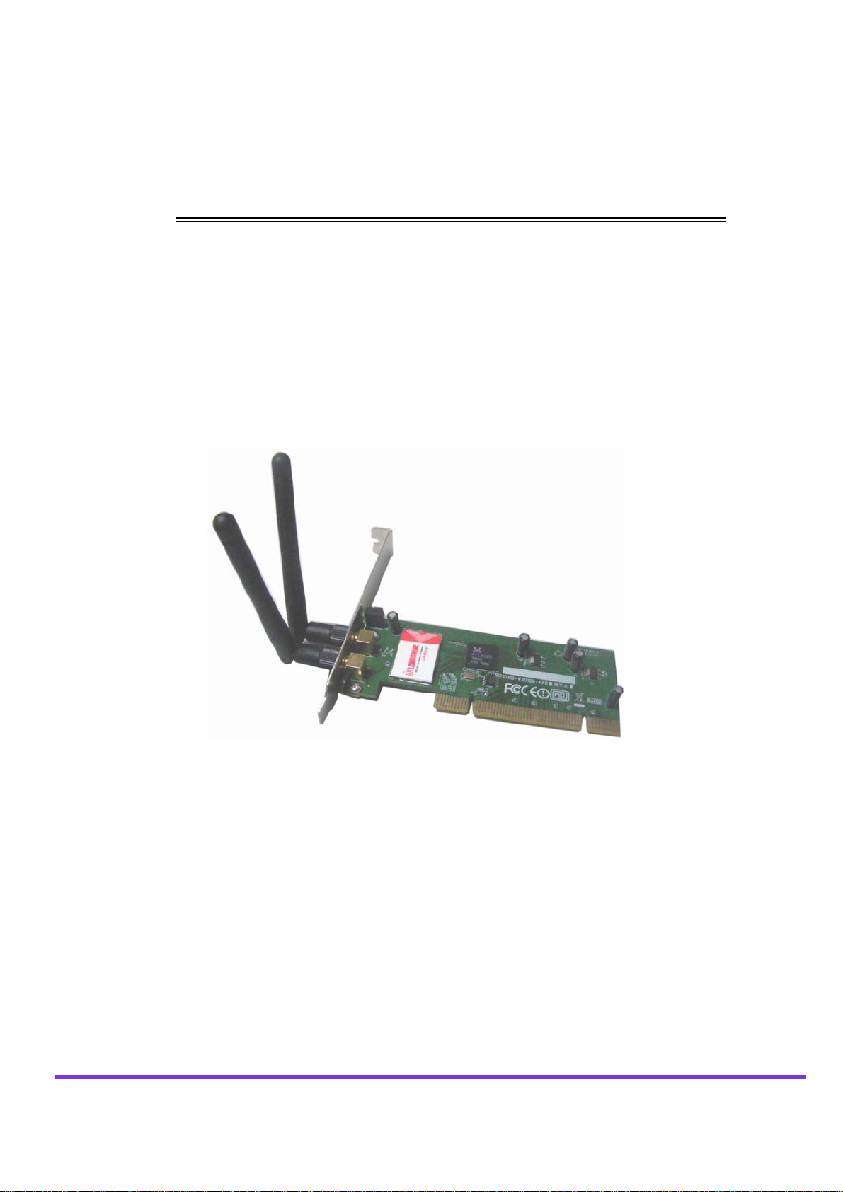
Wireless 1T2R PCI Card
User Manual
Page 2

Wireless 11n 1T2R PCI Card
FCC Certifications
Federal Communication Commission Interference Statement
This equipment has been tested and found to comply with the limits for a Class B digital device,
pursuant to Part 15 of the FCC Rules. It also obtains FCC Certifications (FCC ID is
NOI-W301).These limits are designed to provide reasonable protection against harmful interference
in a residential installation. This equipment generates, uses and can radiate radio frequency energy
and, if not installed and used in accordance with the instructions, may cause harmful interference to
radio communications. However, there is no guarantee that interference will not occur in a particular
installation. If this equipment does cause harmful interference to radio or television reception, which
can be determined by turning the equipment off and on, the user is encouraged to try to correct the
interference by one of the following measures:
-Reorient or relocate the receiving antenna.
-Increase the separation between the equipment and receiver.
-Connect the equipment into an outlet on a circuit different from that to which the receiver is
connected.
-Consult the dealer or an experienced radio/TV technician for help.
This device complies with Part 15 of the FCC Rules. Operation is subject to the following two
conditions: (1) This device may not cause harmful interference, and (2) this device must accept any
interference received, including interference that may cause undesired operation.
FCC Caution: Any changes or modifications not expressly approved by the party responsible for
compliance could void the user's authority to operate this equipment.
IMPORTANT NOTE:
FCC Radiation Exposure Statement:
This equipment complies with FCC radiation exposure limits set forth for an uncontrolled
environment. This equipment should be installed and operated with minimum distance 20cm
between the radiator & your body.
This transmitter must not be co-located or operating in conjunction with any other antenna or
transmitter.
IEEE 802.11b/g or 802.11n operation of this product in the U.S.A. is firmware-limited to channels 1
through 11.
- 2 -
Page 3

Wireless 11n 1T2R PCI Card
CE Mark Warning
This equipment complies with the requirements relating to electromagnetic compatibility, EN 55022
Class B for ITE, the essential protection requirement of Council Directive 2004/108/EC on the
approximation of the laws of the Member States relating to electromagnetic compatibility and
R&TTE Directive 1999/5/EC to meet the regulation of the radio equipment and telecommunications
terminal equipment.
Company has an on-going policy of upgrading its products and it may be possible that information in
this document is not up-to-date. Please check with your local distributors for the latest information.
No part of this document can be copied or reproduced in any form without written consent from the
company.
Trademarks:
All trade names and trademarks are the properties of their respective companies. Copyright ©2010,
All Rights Reserved.
- 3 -
Page 4

Wireless 11n 1T2R PCI Card
Package Contents
The following contents should be found in your box:
One IEEE 802.11n 1T2R PCI Card
Two antennas
One resource CD, including:
REALTEK 11n PCI Wireless LAN Driver and Utility
User’s Manual
Note:
Make sure that the package contains the above items. If any of the listed items are damaged or
missing, please contact with your distributor.
- 4 -
Page 5

Wireless 11n 1T2R PCI Card
NTENTS
CO
Chapter 1 Introduction........................................................................................................................................ 6
1.1 Overview of the Product......................................................................................................................6
1.2 Features..............................................................................................................................................6
1.3 Application Diagram............................................................................................................................. 7
1.4 LED Status.......................................................................................................................................... 7
Chapter 2 Installation Guide for Windows..........................................................................................................8
2.1 Hardware Installation........................................................................................................................... 8
2.2 Software Installation............................................................................................................................8
2.2.1 Overview ........................................................................................................................8
2.2.2 Software Installation........................................................................................................9
Chapter 3 Management Guide..........................................................................................................................12
3.1 Making A Basic Network Connection..................................................................................................12
3.1.1 Select A Configuration Tool............................................................................................12
3.1.2 To Connect with Microsoft Zero Configuration Tool...........................................................12
3.1.3 To Connect with 802.11n Wireless LAN Utility..................................................................13
3.2 Introduction to the 802.11n Wireless LAN Utility.............................................................................14
3.2.1 Interfaces.....................................................................................................................14
3.2.2 Available Network .........................................................................................................15
3.2.3 Profile..........................................................................................................................17
3.2.4 General ........................................................................................................................20
3.2.5 Advanced.....................................................................................................................21
3.2.6 Status..........................................................................................................................22
3.2.7 Statistics......................................................................................................................23
3.2.8 Wi-Fi Protect Setup.......................................................................................................24
Chapter 4 Introduction for Vista User................................................................................................................27
4.1 Installation..........................................................................................................................................27
4.1.1 Overview ......................................................................................................................27
4.1.2 Software Installation for Vista.........................................................................................27
4.2 Management Guide............................................................................................................................30
4.2.1 Interfaces.....................................................................................................................30
4.2.2 Available Network .........................................................................................................31
4.2.3 Profile..........................................................................................................................32
4.2.4 General ........................................................................................................................35
4.2.5 Advanced.....................................................................................................................37
4.2.6 Status..........................................................................................................................37
4.2.7 Statistics......................................................................................................................39
4.2.8 Wi-Fi Protect Setup.......................................................................................................40
Chapter 5 Introduction for Windows 7...............................................................................................................42
4.1 Installation..........................................................................................................................................42
4.2 Management Guide............................................................................................................................44
4.2.1 Interfaces.....................................................................................................................44
4.2.2 Available Network .........................................................................................................45
4.2.3 Profile..........................................................................................................................47
4.2.4 General ........................................................................................................................49
4.2.5 Advanced.....................................................................................................................51
4.2.6 Status..........................................................................................................................51
4.2.7 Statistics......................................................................................................................53
4.2.8 Wi-Fi Protect Setup.......................................................................................................54
Appendix A: Specifications................................................................................................................................57
Appendix B: Glossary........................................................................................................................................58
- 5 -
Page 6

Wireless 11n 1T2R PCI Card
Chapter 1 Introduction
Thank you for purchasing this product. Read this chapter to know about your IEEE 802.11n wireless
1T2R PCI Adapter.
1.1 Overview of the Product
Comply with 802.11n Standards
The IEEE 802.11n Wireless 1T2R PCI adapter provides users to launch IEEE 802.11n wireless
network at 300 Mbps in the 2.4GHz band, which is also compatible with IEEE 802.11b/g wireless
devices at 11/54 Mbps.
Reliable Coverage
The PCI Card adopts MIMO with two external detachable omni directional antennas providing even
better wireless performance, transmission rates, stability and coverage. You can configure this
adapter with ad-hoc mode to connect to other 2.4GHz wireless computers, or with infrastructure
mode to connect to a wireless AP or wireless router for accessing to Internet.
Enhanced Wireless Security and Privacy
This adapter includes a convenient utility for scanning available networks and saving preferred
networks that users usually connected with. Also, this product supports WPA/WPA2 encryptions
and mechanisms, allowing users to quickly and easily configure wireless security.
1.2 Features
Support : 2.4GHz Frequency band, MIMO 1T2R
High Speed transfer data rate up to 300 Mbps
Support QoS Enhancement ( WMM, WMM-SA Client mode)
Supports wireless data encryption with 64/128-bit WPA, WPA2
Support MIMO Power saving mechanism
Complies with PCI 2.3
Compliant with FCC Part 15.247 for US, ETS 300 328 for Europe
Supports 2 SMA antennas (Standard 1.8 dB)
Driver support Windows 7, 2000, 2003, XP 32/ 64, Vista 32/64, Linux, MAC
- 6 -
Page 7
Wireless 11n 1T2R PCI Card
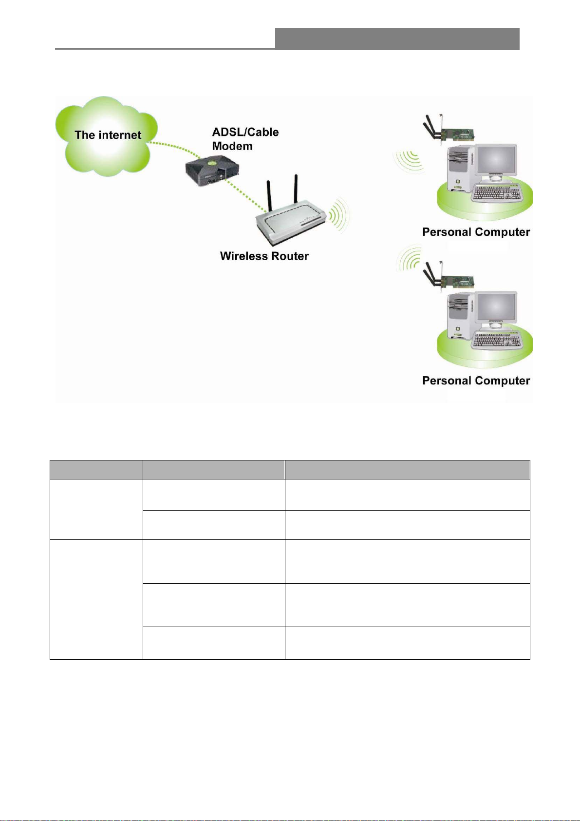
1.3 Application Diagram
1.4 LED Status
LED Indications Status Working Status
Off The adapter is link down
Link LED
Green The adapter is already connected
The adapter is already connected but is not
transmitting or receiving data
The adapter is activity and transmitting of
receiving data.
Act LED
Green and flashing slowly
Green and fast flashing
Off The adapter is Radio off
- 7 -
Page 8
Wireless 11n 1T2R PCI Card
Chapter 2 Installation Guide for Windows
2.1 Hardware Installation
1. Make sure the computer is turned off. Remove the expansion slot cover from the computer.
2. Carefully slide the Wireless 1T2R PCI Card into the PCI slot. Push evenly and slowly and make
sure it is properly seated.
3. Secure the antennas on.
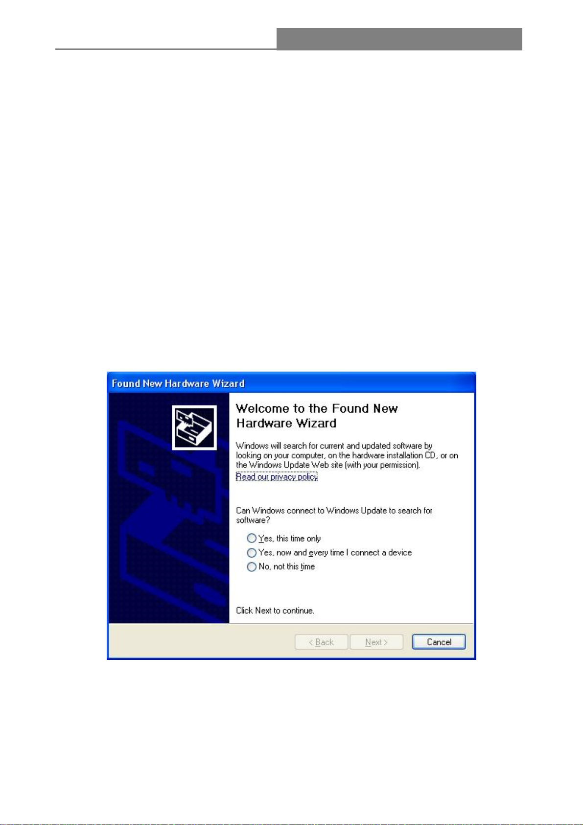
4. Turn on your computer. Windows detects the new hardware automatically.
2.2 Software Installation
2.2.1 Overview
The following driver installation guide uses Windows XP as the presumed operation system. The
procedures and screens in Windows 2000 are familiar with Windows XP.
1. The system finds the newly installed device automatically. Click Cancel to close this window.
- 8 -
Page 9
Wireless 11n 1T2R PCI Card
2.2.2 Software Installation
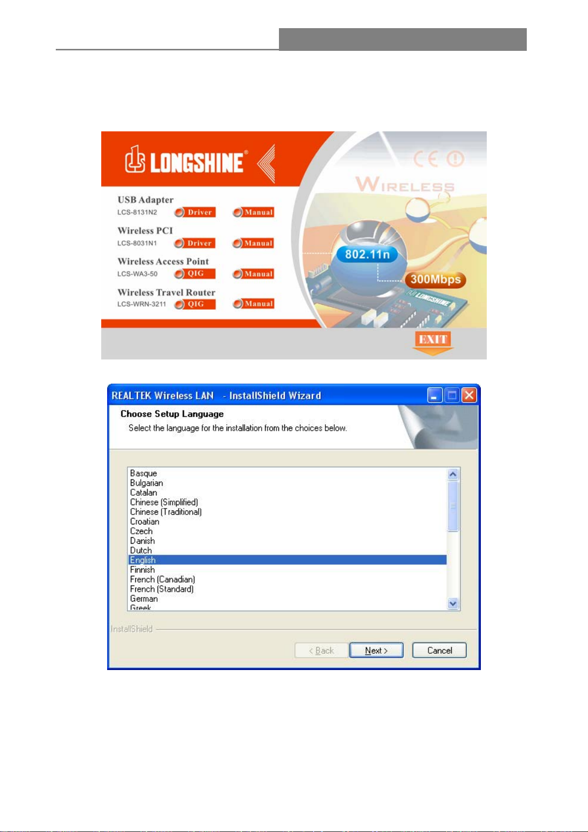
1. Insert the CD into your CD-Rom, and then appear an interface. Please click on PCI-E> Driver>
Win to start the installation.
2. The language-selecting window pops up. Please select the language you use and click “Next”.
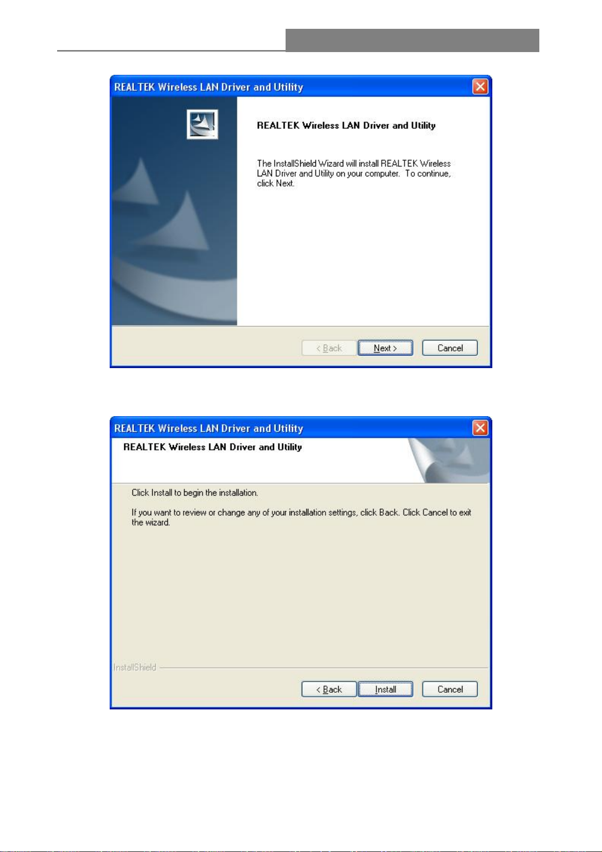
3. The welcome window pops up. Click the “Next” button to proceed.
- 9 -
Page 10
Wireless 11n 1T2R PCI Card
4. Click the “Install” button to start installing.
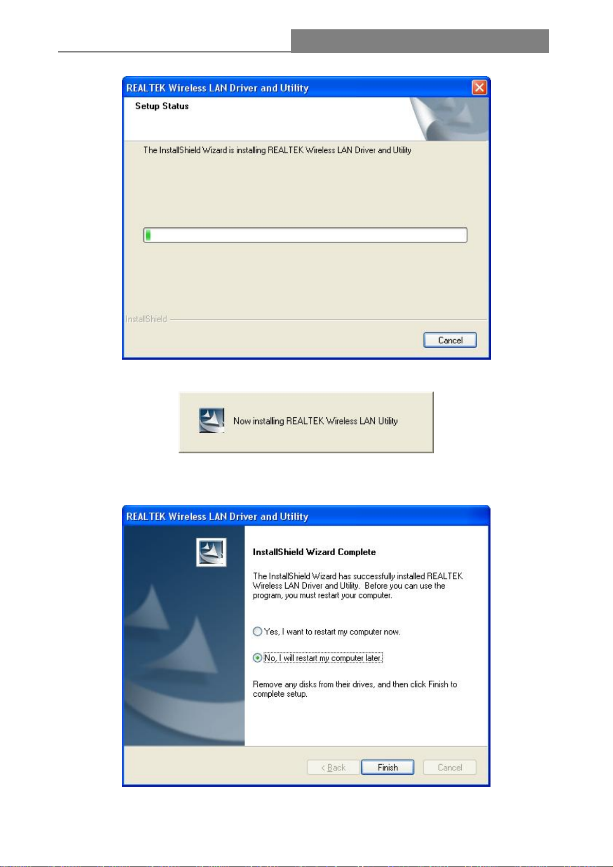
5. Please wait while installation.
- 10 -
Page 11
Wireless 11n 1T2R PCI Card
6. Please wait again while installation
7. After all the steps above, you will see the screen below, select “Yes” or “No” to reboot the
system, then click Finish
- 11 -
Page 12
Wireless 11n 1T2R PCI Card
Chapter 3 Management Guide
This chapter describes how to configure your Adapter for wireless connectivity on your Wireless
Local Area Network (WLAN) and use the data security encryption features.
The configuration of the adapter in Windows XP is similar with that in Windows 2000. This User
Guide takes Windows XP for example.
After Installing the Adapter, the Adapter’s tray icon will appear in your system tray. It appears at the
bottom of the screen, and shows the signal strength using color and the received signal strength
indication (RSSI).
There is no connection.
If the icon is green, there is good signal strength.
If the icon is green, there is excellent signal strength.
Read this chapter to understand the management interface of the device and how to manage the
device.
3.1 Making A Basic Network Connection
3.1.1 Select A Configuration Tool
In the following instruction for making a network connection, we use the provided Utility to configure
your wireless network settings.
Note: You could use either the software we provide or Microsoft Zero Configuration tool to
configure this adapter.
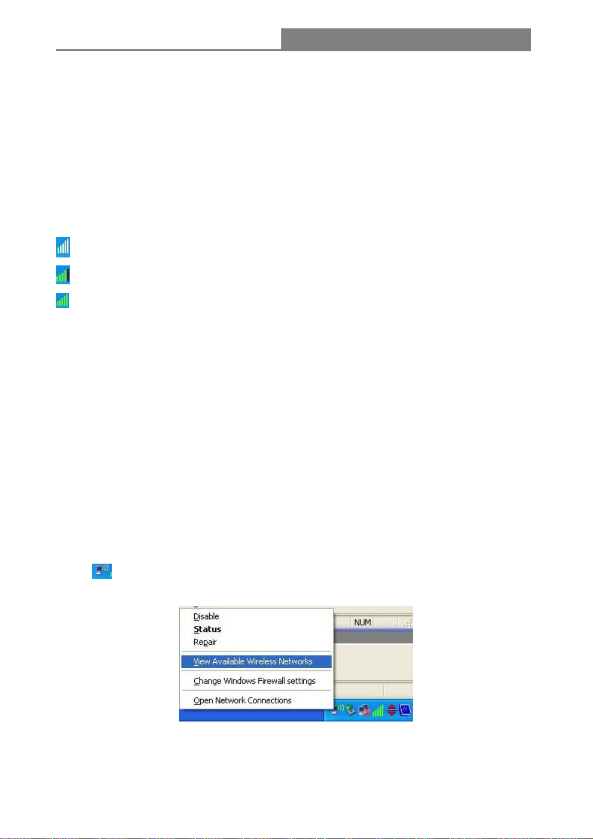
3.1.2 To Connect with Microsoft Zero Configuration Tool
After specifying the Microsoft Zero Configuration tool to configure your wireless network, right click
on the
network.
icon on system tray. Select “View Available Wireless Networks” to specify your wireless
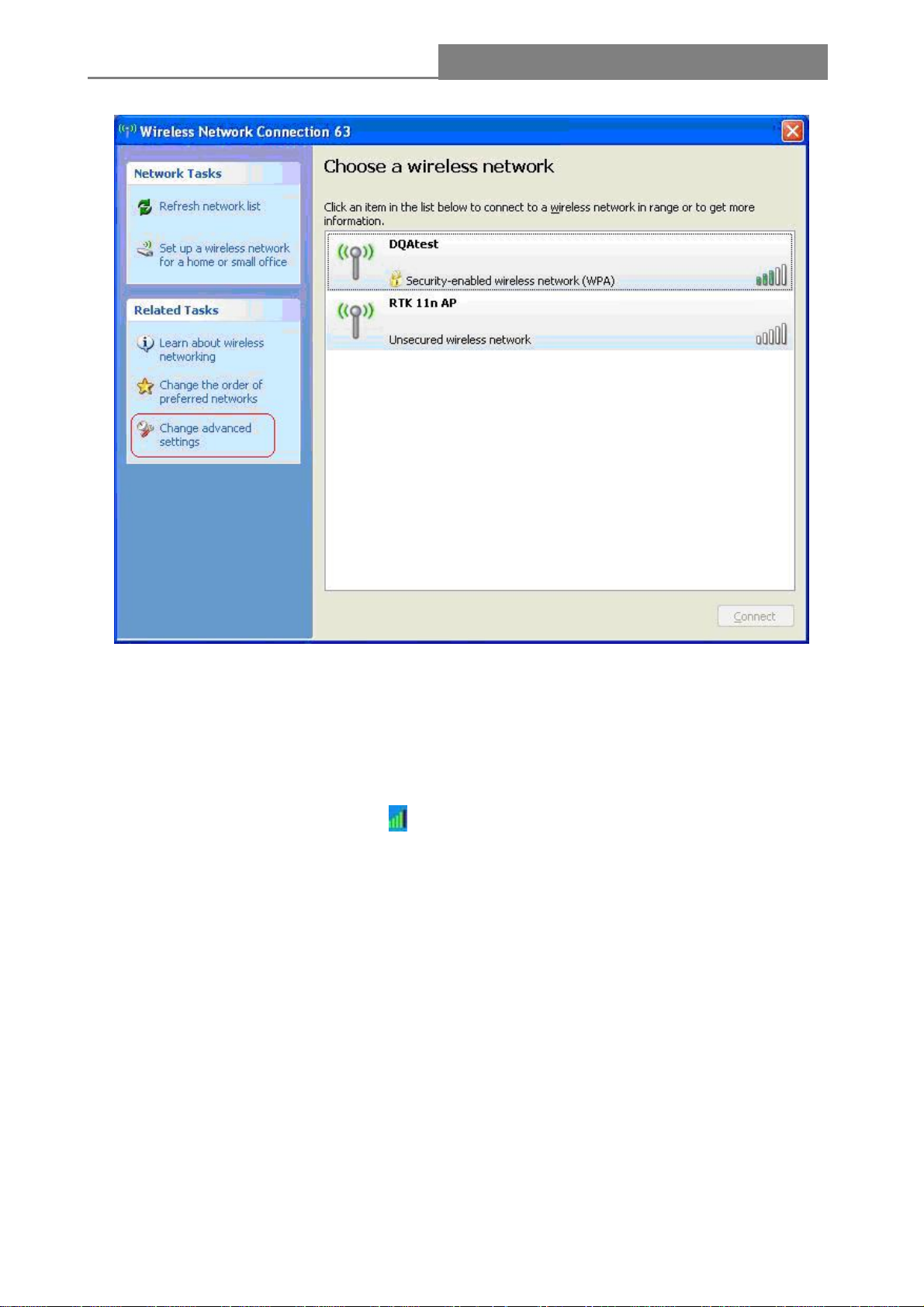
The tool shows the available wireless networks. Select your demanding network to connect with. To
connect to a wireless network, please click Change advanced settings to be compatible with your
wireless network settings.
- 12 -
Page 13
Wireless 11n 1T2R PCI Card
3.1.3 To Connect with 802.11n Wireless LAN Utility
We provide this Utility for users to connect to a wireless network easily. It provides more information
and configuration for this adapter. As default, the Utility is started automatically upon starting your
computer and connects to a connectable wireless network with best signal strength and with no
security setting. Right click on the icon
Utility does not start. Please refer to the following chapters to get information regarding to the
functions of this Utility.
in the system tray and select Open Config utility if the
- 13 -
Page 14
Wireless 11n 1T2R PCI Card
3.2 Introduction to the 802.11n Wireless LAN Utility
Note: The Utility in Linux and Mac are different from the following.
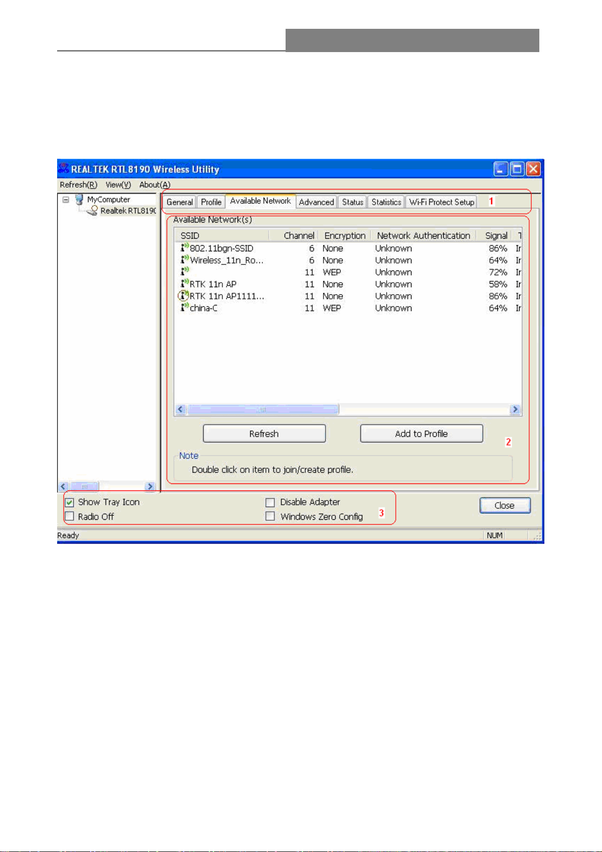
3.2.1 Interfaces
1. Functional Buttons: on top of the window. You can click each button to access each
configuration window.
2. Configuration Column: Center of the Utility window. Make your changes for each function in
this part.
3. Optional Table: “Show Tray Icon”, “Disable Adapter”, “Radio off”, “Windows Zero Config”
Each control item affects the adaptor or management GUI directly.
A. Show Tray Icon---Clicking "Show Tray Icon" and “Close” button, the management GUI will be
minimized and stay on the tray icon located at the right bottom corner of Windows. If not,
management GUI will shut down by only click "Close" button with unchecked condition.
- 14 -
Page 15

Wireless 11n 1T2R PCI Card
B. Disable Adapter---Disable this wireless PCI card
C. Radio off---It can save power while turning off the radio. While the radio is off, the links with
other wireless network will be disconnected. User should be aware that while the wireless
configuration is in AP mode. The radio off will cause the sub network belonging to the AP to be
disconnected with internet.
D. Windows Zero Config---External Configuration (Windows XP only): select this item will enables
you to disable the WLAN Station Configuration Utility and indicates that the station driver is to be
configured with Windows XP’s built-in Zero Configuration Utility. This item is only displayed on
windows XP systems.
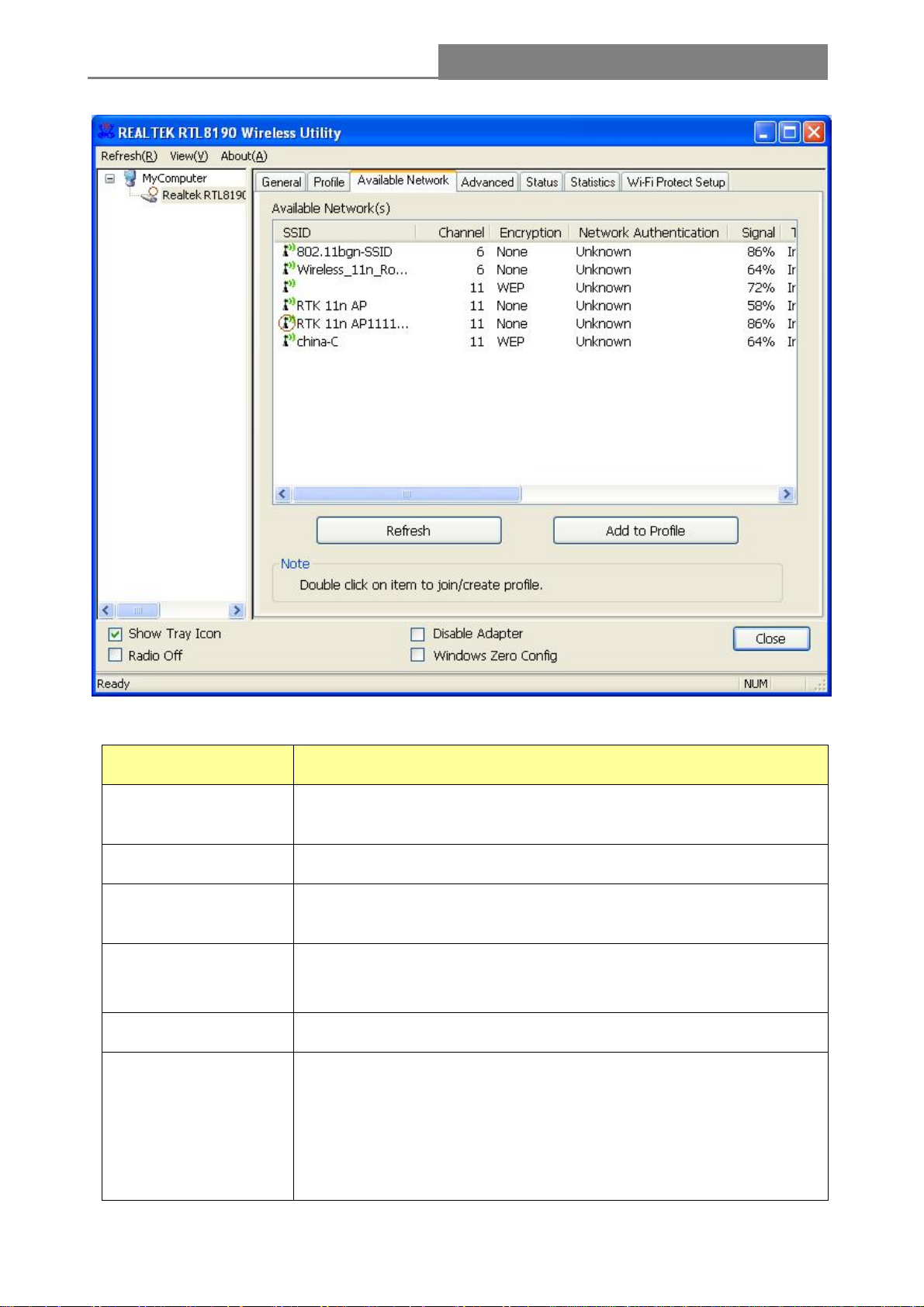
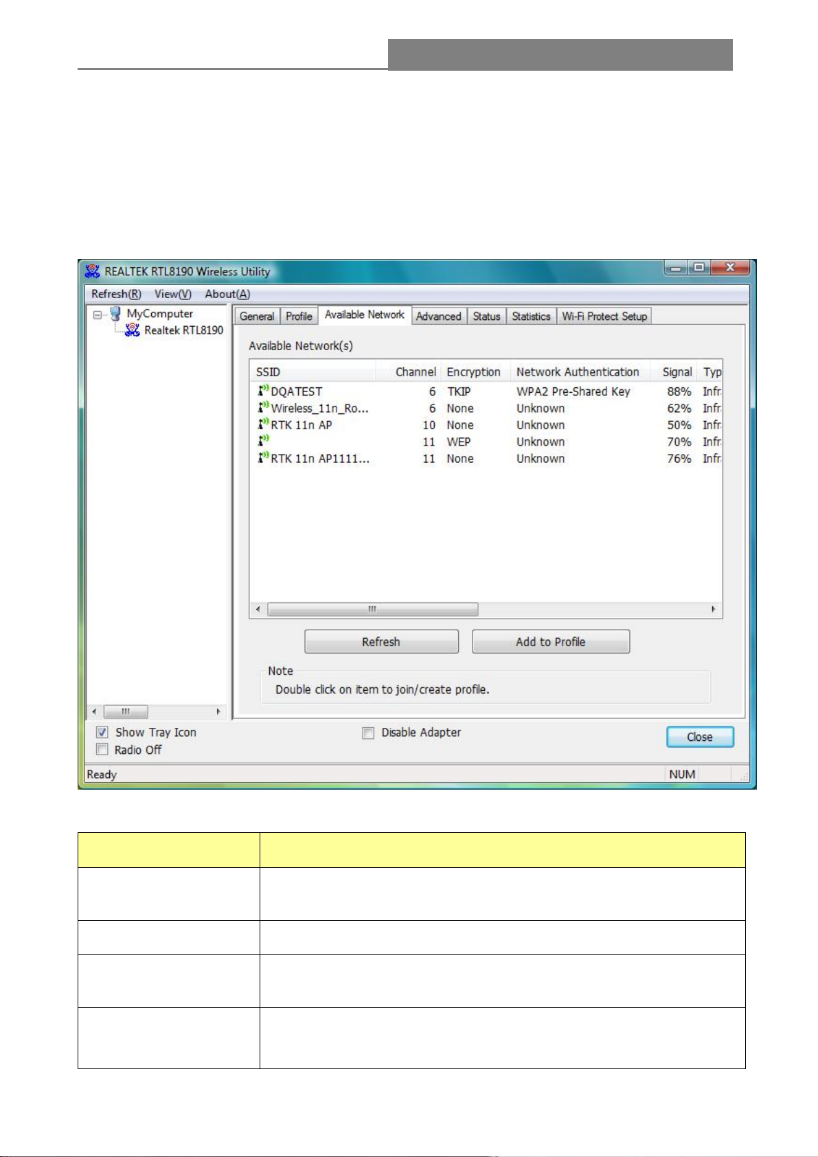
3.2.2 Available Network
This network lists the available wireless networks. The Utility connects to a wireless network with
best signal strength automatically. You can refresh the connecting network by clicking on the
network name and click the Refresh button. In the center of the Utility windows, you will see detail
information of each network.
- 15 -
Page 16
Wireless 11n 1T2R PCI Card
Available Network Information:
Items Information
SSID
Channel
Encryption
Network
Authentication
Signal
Type
The name of the IEEE 802.11 wireless network. This field has a
maximum limit of 32 characters.
Display current channel in use.
Shows the encryption mode in use. There are total 4 modes: None,
WEP, TKIP and AES.
Shows the authentication mode in use.
This percentage shows the strength of the signal.
The type of network and the station currently connected are shown
here. The options include :
• Infrastructure - All wireless clients will connect to an access point
or wireless router.
• Ad-Hoc - Directly connecting to another computer, for peer-to-peer
- 16 -
Page 17
Wireless 11n 1T2R PCI Card
communication, using wireless network adapters on each computer,
such as two or more wireless adapters.
BSSID
Support Rates
Note:
1) An Infrastructure network contains an Access Point or wireless router. All the wireless devices or
clients will connect to the wireless router or access point.
2) An Ad-Hoc network contains only clients, such as laptops with wireless desktop adapters. All the
adapters must be in Ad-Hoc mode to communicate.
The IEEE MAC address of locally-managed, generating from a 46
random code.
Show current rate
3.2.3 Profile
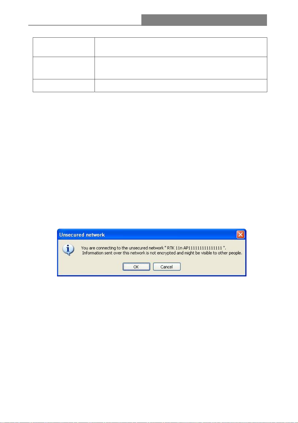
1. Add a new profile:
(1) Selecting an available network in the “Available Network” function then click the Add to Profile
button., or double click the network name. You could also add a new profile quickly by clicking the
Add button in the “Profile” function.
Note: If the network you add to profile is not encrypted, “Unsecured network” window will pop up,
then Click “OK”.
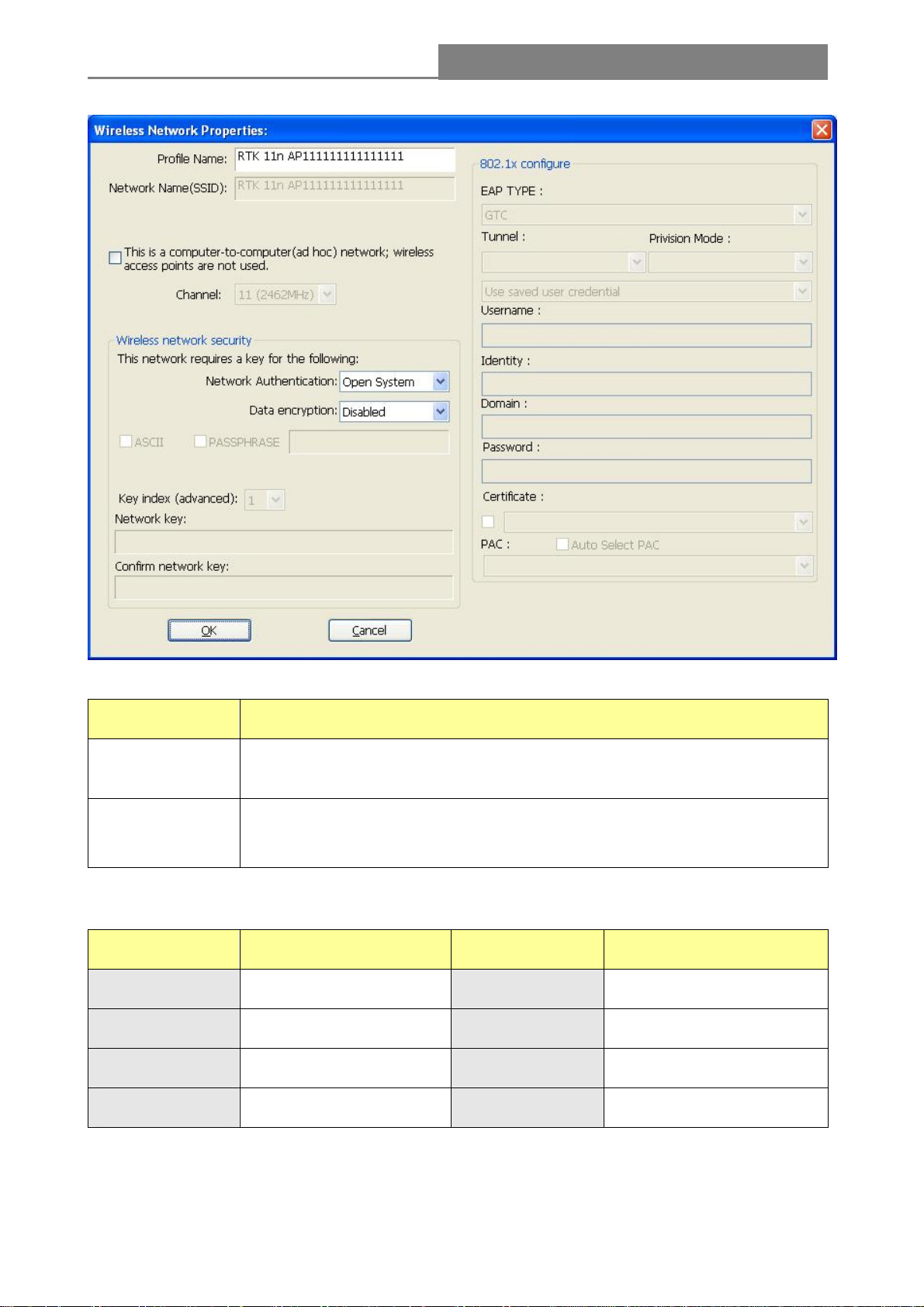
(2) It displays “Wireless Network Properties” dialog box. This profile page allows users to save
different wireless settings, which helps users to get access to wireless networks at home, office or
other wireless network environments quickly.
- 17 -
Page 18
Wireless 11n 1T2R PCI Card
In this dialog box, there are some items:
Items Information
Profile Name
Network
Name(SSID)
Identifies the configuration profile .This name must be unique. Note that the
profile names are not case-sensitive.
The IEEE 802.11n wireless network name, using default name defined by
system. This field has a maximum limit of 32 characters.
(3) Channel (Country Region Code): seven countries to choose. Country channel list:
Country Channel Range Country Channel Range
USA CH1 ~ CH11 FRANCE CH10 ~ CH13
CANADA CH1 ~ CH11 JAPAN CH1 ~ CH14
ETSI CH1 ~ CH13 ISRAEL CH1 ~ CH13
SPAIN CH10 ~ CH11
- 18 -
Page 19

Wireless 11n 1T2R PCI Card
(4) Wireless Network Security
A. Network Authentication
There are 7 types supported: Open System, Shared Key , WPA-PSK, WPA2-PSK, and WPA 802.1X,
WPA2 802.1X, WEP 802.1X. Please select a type from the drop down list.
Open System: enable an adapter to attempt authentication regardless of its WEP settings. It
will only associate with the access point if the WEP keys on both the adapter and the access
point match.
Shared-key: only allows the adapter to associate with access points that have the same WEP
key.
802.1x: This item appears while the environment is set to an open authentication with WEP
encryption. The section is also available in WPA and WPA2 authentication types.
Preshared Key (PSK): This is the shared secret between AP and STA. For WPA-PSK,
WPA2-PSK and WPA-NONE authentication mode, this field must be filled with characters
longer than 8 and less than 32 lengths.
WEP Key: Only a vailable when using WEP encryption algorithm. The key must match AP's
key. Only using the same cryptographic key to access the computer, the internet can storage,
and decryption the information from other computer.
B. Data Encryption:
There are 4 types supported: Disabled, WEP, TKIP and AES. The available
encryption selection will differ from the authentication type you have
chosen, the result is shown below:
Authentication Available Encryption Selection
Data encryption
Note: Select different Security Options, the configurations are different; you can select the
Open System Disabled, WEP
Shared Key , WEP 802.1X WEP
WPA-PSK, WPA2-PSK, and WPA TKIP , AES
802.1X, WPA2 802.1X, WPA CCKM,
WPA2 CCKM
appropriate security option and configure the exact key as your need.
TKIP: "Temporary Key Integration communication Protocol", it provide each packet's key
mixture, message integration and key reconstruction mechanism. TKIP can use with personal
or the enterprise network validation.
AES: “Advanced Encryption Standard”, it is a new method that the wireless transmission of
privacy protection. AES encryption methods provides more careful than TKIP.
(5) Finish the configuration, then click “OK”, that network has been added to the profile.
- 19 -
Page 20

Wireless 11n 1T2R PCI Card
Profile List: The list shows all the profiles you have added before.
Buttons: You can click on these buttons to Add a new profile, Remove, Edit, Duplicate or Set
Default an old profile.
3.2.4 General
In this window, there are some items as following:
- 20 -
Page 21

Wireless 11n 1T2R PCI Card
Items Information
Status
Speed
Type
Encryption
SSID
Signal Strength
Link Quality
Network Address
3.2.5 Advanced
Currently connection status
Show current transmit rate and receive rate
Network type in use
Encryption type in use
The name of the IEEE 802.11 wireless network. This field has a
maximum limit of 32 characters
Receive signal strength
Display connection quality based on signal strength
A. MAC Address : The MAC address of the wireless network adapter.
B. IP Address : IP address of current connection.
C. Subnet Mask : Subnet mask of current connection.
D. Gateway : Gateway of current connection.
This screen below allows you to make advanced configuration for the profile. Please refer to the
following chart for definitions of each item.
1. Preamble Mode
- 21 -
Page 22

Wireless 11n 1T2R PCI Card
The length of CRC blocks in the frames during the wireless communication. Select the options from
the drop list : (1) Long (2)Short (3)Auto.
2. Channel Plan
The selected Country: FCC, IC, ETSI, Spain, France, MKK, MKK1, Israel, TELEC, Default
3. Threshold
(1) Fragment Threshold
This value should remain at its default setting of 2347. If you experience a high packet error rate,
you may slightly increase your fragmentation threshold within the value range of 256 to 2432.
Setting the fragmentation threshold too low may result in poor performance.
(2) RTS Threshold
Request To Send threshold. This value should remain at its default setting of 2346. If you encounter
inconsistent data flow, only minor modifications to the value range between 0 and 2432 are
recommended.
3.2.6 Status
The Status tab contains general information about the program and its operations. The current
Status tab needn’t any configurations.
The following table describes the items found on the Status screen.
- 22 -
Page 23

Wireless 11n 1T2R PCI Card
Items Information
Manufacturer
NDIS Driver Version
Encryption
Authenticate
Channel Set
MAC Address
Data Rate(Auto)
Channel Frequency
Status
SSID
Network Type
The name of manufacturing this product
The version of
Here displays the encryption type the device is using
This shows whether the server based authentication is used.
Network Driver Interface Specification
Appear the country you use
The MAC address of the wireless network adapter.
Show current transmit rate and receive rate
Shows the channel in use (1~14)
Current connection status
The SSID of the wireless system.
The type of network and the station currently connected are shown
here. The options include : Infrastructure, Ad Hoc
The power save mode have three mode, as follows :
• Max - Selects maximum mode to let the access point buffer
incoming messages for the Adapter. The Adapter will detect the
access point if any messages are waiting periodically.
Power Save Mode
• Min – Min mode uses minimum when retrieving a large number of
packets, then switches back to power save mode after retrieving
the packets.
• None - Turns power saving off, thus powering up the Wireless
PCI Adapter continuously for a short message response time.
Associated AP MAC
Up Time
The MAC Address of associated AP
Record life time
3.2.7 Statistics
Statistics page displays the detail counter information based on 802.11 MIB counters. This page
translates the MIB counters into a format easier for user to understand. It show receiving and
transmitting statistical information about the following receiving and transmitting diagnostics for
frames received by or transmitted to the wireless network adapter.
- 23 -
Page 24

Wireless 11n 1T2R PCI Card
Items
TX OK
TX Error
RX OK
Rx Packet Count
RX Retry
RX ICV Error
Reset Counter
Information
Successfully transmitted frames numbers.
Frames numbers transmitting with error.
Successfully received frames numbers.
The packets of receiving frames
Frames numbers re-receiving
Integrity Check Value receiving with error.
Reset counters to zero.
3.2.8 Wi-Fi Protect Setup
The primary goal of Wi-Fi Protected Setup (Wi-Fi Simple Configuration) is to simplify the security
setup and management of Wi-Fi networks. This adapter supports the configuration setup using PIN
configuration method or PBC configuration method. If the wireless card supports Wi-Fi Protected
Setup (WPS), you can establish a wireless connection between wireless card and router or AP
- 24 -
Page 25

Wireless 11n 1T2R PCI Card
using either Push Button Configuration (PBC) method or PIN method.
Here we will introduce two ways to configure the QSS
(QSS is known as rapid security settings, by pressing the wireless router and wireless card on the
QSS button to automatically set up WPA2 secure connection level without the router or network
adapter management software to conduct the cumbersome interface settings, greatly simplifying
the operation of the wireless security settings.)
Pin Code: 8-digit numbers. It is randomly generated from system
1. PIN method
Click the button “Pin Input Config (PIN)”, and then come to the following figure.
Click the button “Yes”, you can select one of the AP.
In this figure, you can operate these buttons “Refresh / Select / Cancel”. Select the name of one AP,
then click “Select” button, you could use PIN method to configure the QSS.
- 25 -
Page 26

Wireless 11n 1T2R PCI Card
Double click the Internet WEB browser icon on your desktop screen. Type the IP address of you
selected router/AP into the URL and press Enter, and then you can enter the configuration.
Please enter the WPS ( Wi-Fi ) configuration page, type the PIN code of adapter and click confirm
button to build WPS connection. WPS connection will be successful by PIN method after several
minutes.
2. PBC (Push Button Configuration) method
After pushing the PBC button, please push the physical button on your AP or visual button on the
WPS config page, then come to the following figure.
Please enter the WPS ( Wi-Fi ) configuration page of your desired router/AP, and then start PBC
connection. WPS connection will be successful by PBC method after several minutes.
- 26 -
Page 27

Wireless 11n 1T2R PCI Card
Chapter 4 Introduction for Vista User
4.1 Installation
4.1.1 Overview
The Adapter’s Setup Wizard will guide you through the Installation procedure for Vista. The Setup
Wizard will install the REALTEK 11n PCI Wireless LAN Driver and Utility. When you install the
hardware prior to before installing the software, the system will prompt “Found New Hardware
Wizard”, click Cancel, and run the Setup Wizard program on the CD-ROM.
4.1.2 Software Installation for Vista
1. Insert the CD into your CD-Rom, and then appear an interface. Please click on PCI> Driver>
Win to start the installation.
- 27 -
Page 28

Wireless 11n 1T2R PCI Card
2. The language-selecting window pops up. Please select the language you use and click “Next”.
3. The welcome window pops up. Click the “Next” button to proceed.
- 28 -
Page 29

Wireless 11n 1T2R PCI Card
4. Click the “Install” button to start installing.
5. Please wait again while installation
6. After all the steps above, you will see the screen below, click Finish to reboot the system.
- 29 -
Page 30

Wireless 11n 1T2R PCI Card
4.2 Management Guide
This chapter describes how to configure your Adapter for wireless connectivity on your Wireless
Local Area Network (WLAN) and use the data security encryption features.
After Installing the Adapter, the Adapter’s tray icon will appear in your system tray. It appears at the
bottom of the screen, and shows the signal strength using color and the received signal strength
indication (RSSI).
4.2.1 Interfaces
1. Functional Buttons : on top of the window. You can click each button to access each
configuration window.
2. Configuration Column : Center of the Utility window. Make your changes for each function in
this part.
3. Optional Table : “Show Tray Icon”, ”Disable Adapter”, ”Radio off”,
- 30 -
Page 31
Wireless 11n 1T2R PCI Card
4.2.2 Available Network
This network lists the available wireless networks. The Utility connects to a wireless network with
best signal strength automatically
network name and click the Refresh button. In the center of the Utility windows, you will see detail
information of each network.
. You can refresh the connecting network by clicking on the
Available Netw rmation: ork Info
Items Information
SSID
Channel
E
ncryption
Network
Authentication
- 31 -
The name of the IEEE 802.11 wireless network. This field has a
maximum limit of 32 characters.
Display current channel in use.
Shows the encryption mode in use. There are total 4 modes: None,
WEP, TKIP and AES.
Shows the authentication mode in use.
Page 32

Wireless 11n 1T2R PCI Card
Signal
This percentage shows the strength of the signal.
Type
here. The options include : Infrastructure , Ad-Hoc
BSSID
Support Rates
The IEEE MAC address of locally-managed, generating from a 46
random code.
Show current rate
4.2.3 Profile
1. Add a new profile:
(1) Selecting an available network in the
Profile button
, or double click the network name. You could also add a new profile quickly by
“Available Network” function then click the Add to
clicking the Add button in the “Profile” function.
Note: If the network
up
, then Click “OK”.
you add to profile is not encrypted, “Unsecured network” window will pop
ected are shown The type of network and the station currently conn
- 32 -
Page 33

Wireless 11n 1T2R PCI Card
(2) It displays “Wireless Network Properties” dialog box. This profile page allows users to save
different wireless settings, which helps users to get access to wireless networks at home, office or
other wireless network environments quickly.
(3). Channel (Country Region Code): seven countries to choose. Country channel list:
Country Channel Range Country Channel Range
USA CH1 ~ CH11 FRANCE CH10 ~ CH13
CANADA CH1 ~ CH11 JAPAN CH1 ~ CH14
- 33 -
Page 34

Wireless 11n 1T2R PCI Card
ETSI CH1 ~ CH13 ISRAEL CH1 ~ CH13
SPAIN CH10 ~ CH11
(4) Wireless Network Security
A. Network Authentication
Select the Security tab in the screen above. To define the security mode, select the desired secur ity
mode as follows. There are 7 types supported: Open System, Shared Key, WPA-PSK, WPA2-PSK,
and WPA 802.1X, WPA2 802.1X, WEP 802.1X, Please select a type from the drop down list
B. Data Encryption:
There are 4 types supported: Disabled, WEP, TKIP and AES. The
available encryption selection will differ from the authentication type
you have chosen, the result is shown below:
Authentication Available Encryption Selection
Data
encryption
Note: Select different Security Options, the configurations are different; you can select the
appropriate security option and configure the exact key as your need.
Open System Disabled, WEP
Shared Key WEP
WPA-PSK, WPA2-PSK, and
WPA 802.1X, WPA2 802.1X
WEP 802.1X WEP
TKIP, AES
(5) Finish the configuration, and then click “OK”, that network has been added to the profile.
- 34 -
Page 35

Wireless 11n 1T2R PCI Card
Profile List: The list shows all the profiles you have added before.
Buttons: You can click on these buttons to Add a new profile, Remove, Edit, Duplicate or Set
Default an old profile.
4.2.4 General
- 35 -
Page 36

Wireless 11n 1T2R PCI Card
In this window, there are some items as following:
Items Information
Status
Speed
Type
Encryption
SSID
Signal Strength
Link Quality
Network
Address
Currently connection status
Show current transmit rate and receive rate
Network type in use.
Encryption type in use.
The name of the IEEE 802.11 wireless network. This field has a maximum
limit of 32 characters.
Receive signal strength
Display connection quality based on signal strength
A. MAC Address : The MAC address of the wireless network adapter.
B. IP Address : IP address of current connection.
C. Subnet Mask : Subnet mask of current connection.
D. Gateway : Gateway of current connection.
- 36 -
Page 37

Wireless 11n 1T2R PCI Card
4.2.5 Advanced
This screen below allows you to make advanced configuration for the profile. Please refer to the
following chart for definitions of each item.
4.2.6 Status
The Status tab contains general information about the program and its operations. The current
Status tab needn’t any configurations.
- 37 -
Page 38

Wireless 11n 1T2R PCI Card
The following table describes the items found on the Status screen.
Items Information
Manufacturer
NDIS Driver Version
Encryption
Authenticate
Channel Set
MAC Address
Data Rate(Auto)
Channel Frequency
Status
The name of manufacturing this product
The version of
Here displays the encryption type the device is using
This shows whether the server based authentication is used.
Appears the Channel you use
The MAC address of the wireless network adapter.
Show current transmit rate and receive rate
Shows the channel in use (1~14)
Current connection status
Network Driver Interface Specification
SSID
Network Type
- 38 -
The SSID of the wireless system.
The type of network and the station currently connected are shown
Page 39

Wireless 11n 1T2R PCI Card
here. The options include : Infrastructure, Ad Hoc
Power Save Mode
Associated AP MAC
Up Time
4.2.7 Statistics
Statistics page displays the detail counter information based on 802.11 MIB counters. This page
translates the MIB counters into a format easier for user to understand. It show receiving and
transmitting statistical information about the following receiving and transmitting diagnostics for
frames received by or transmitted to the wireless network adapter.
The power save mode have three mode: Max, Min, None
The MAC Address of associated AP
Record connection time
- 39 -
Page 40

Wireless 11n 1T2R PCI Card
Items
Information
TX OK
TX Error
RX OK
Rx Packet Count
RX Retry
RX ICV Error
Reset Counter
Successfully transmitted frames numbers.
Frames numbers transmitting with error.
Successfully received frames numbers.
The packets of receiving frames
Frames numbers re-receiving
Integrity Check Value receiving with error.
Reset counters to zero.
4.2.8 Wi-Fi Protect Setup
The primary goal of Wi-Fi Protected Setup (Wi-Fi Simple Configuration) is to simplify the security
setup and management of Wi-Fi networks. This adapter supports the configuration setup using PIN
configuration method or PBC configuration method. If the wireless card supports Wi-Fi Protected
Setup (WPS), you can establish a wireless connection between wireless card and router using
either Push Button Configuration (PBC) method or PIN method.
Here we will introduce two ways to configure the QSS
(QSS is known as rapid security settings, by pressing the wireless router and wireless card on the
QSS button to automatically set up WPA2 secure connection level without the router or network
adapter management software to conduct the cumbersome interface settings, greatly simplifying
the operation of the wireless security settings.)
Pin Code: 8-digit numbers. It is randomly generated from system
1. PIN method
Click the button “Pin Input Config (PIN)”, and then come to the following figure.
Click the button “Yes”, you can select one of the AP.
- 40 -
Page 41

Wireless 11n 1T2R PCI Card
In this figure, you can operate these buttons “Refresh / Select / Cancel”. Select the name of one AP,
then click “Select” button, you could use PIN method to configure the QSS.
Double click the Internet WEB browser icon on your desktop screen. Type the IP address of you
selected router/AP into the URL and press Enter, and then you can enter the configuration.
Please enter the WPS ( Wi-Fi ) configuration page, type the PIN code of adapter and click confirm
button to build WPS connection. WPS connection will be successful by PIN method after several
minutes.
2. PBC (Push Button Configuration) method
After pushing the PBC button, Please push the physical button on your AP or visual button on the
WPS config page, then come to the following figure.
Please enter the WPS ( Wi-Fi ) configuration page of your desired router/AP, and then start PCB
connection. WPS connection will be successful by PBC method after several minutes.
- 41 -
Page 42

Wireless 11n 1T2R PCI Card
Chapter 5 Introduction for Windows 7
4.1 Installation
1. Insert the CD into your CD-Rom, and then appear an interface. Please click on PCI> Driver> Win
7 to start the installation.
2. The language selecting interface appears. Please select the language you use and click “Next”.
3. The welcome window pops up. Click the “Next” button to proceed.
- 42 -
Page 43

Wireless 11n 1T2R PCI Card
4. Click the “Install” button to start installing.
5. Please wait again while installation
6. After all the steps above, you will see the screen below. Choose Yes or No at your will and
select Finish to complete the installation.
- 43 -
Page 44

Wireless 11n 1T2R PCI Card
4.2 Management Guide
This chapter describes how to configure your Adapter for wireless connectivity on your Wireless
Local Area Network (WLAN) and use the data security encryption features.
After Installing the Adapter, the Adapter’s tray icon will appear in your system tray. It appears at the
bottom of the screen, and shows the signal strength using color and the received signal strength
indication (RSSI).
4.2.1 Interfaces
- 44 -
Page 45

Wireless 11n 1T2R PCI Card
1. Functional Buttons : on top of the window. You can click each button to access each
configuration window.
2. Configuration Column : Center of the Utility window. Make your changes for each function in
this part.
3. Optional Table : “Show Tray Icon”, ”Disable Adapter”, ”Radio off”.
4.2.2 Available Network
This network lists the available wireless networks. The Utility connects to a wireless network with
best signal strength automatically. You can refresh the connecting network by clicking on the
network name and click the Refresh button. In the center of the Utility windows, you will see detail
information of each network.
- 45 -
Page 46

Wireless 11n 1T2R PCI Card
Available Network Information:
Items Information
SSID
Channel
Encryption
Network
Authentication
Signal
Type
The name of the IEEE 802.11 wireless network. This field has a
maximum limit of 32 characters.
Display current channel in use.
Shows the encryption mode in use. There are total 4 modes: None,
WEP, TKIP and AES.
Shows the status of the authentication mode.
This percentage shows the strength of the signal.
The type of network and the station currently connected are shown
here. The options include : Infrastructure , Ad-Hoc
- 46 -
Page 47

Wireless 11n 1T2R PCI Card
BSSID
The IEEE MAC address of locally-managed, generating from a 46
random code.
Support Rates
4.2.3 Profile
1. Add a new profile:
(1) Selecting an available network in the “Available Network” function then click the Add to
Profile button, or double click the network name. You could also add a new profile quickly by
clicking the Add button in the “Profile” function. Or you could double click you favorite
network to add a new profile.
(2) The next step the windows will display “Wireless Network Properties” dialog box. This profile
page allows users to save different wireless settings, which helps users to get access to wireless
networks at home, office or other wireless network environments quickly.
Show current rate
(3). Channel (Country Region Code): seven countries to choose. Country channel list:
Country Channel Range Country Channel Range
- 47 -
Page 48

Wireless 11n 1T2R PCI Card
USA CH1 ~ CH11 FRANCE CH10 ~ CH13
CANADA CH1 ~ CH11 JAPAN CH1 ~ CH14
ETSI CH1 ~ CH13 ISRAEL CH1 ~ CH13
SPAIN CH10 ~ CH11
(4) Wireless Network Security
A. Network Authentication
Select the Security tab in the screen above. To define the security mode, select the desired secur ity
mode as follows. There are 7 types supported: Open System, Shared Key, WPA-PSK, WPA2-PSK,
and WPA 802.1X, WPA2 802.1X, WEP 802.1X, Please select a type from the drop down list
B. Data Encryption:
There are 4 types supported: Disabled, WEP, TKIP and AES. The
available encryption selection will differ from the authentication type
you have chosen, the result is shown below:
Authentication Available Encryption Selection
Data
encryption
Note: Select different Security Options, the configurations are different; you can select the
appropriate security option and configure the exact key as your need.
Open System Disabled, WEP
Shared Key WEP
WPA-PSK, WPA2-PSK, and
WPA 802.1X, WPA2 802.1X
WEP 802.1X WEP
TKIP, AES
(5) Finish the configuration, and then click “OK”, then the network has been added to the profile.
- 48 -
Page 49

Wireless 11n 1T2R PCI Card
Profile List: The list shows all the profiles you have added before.
Buttons: You can click on these buttons to Add a new profile, Remove, Edit, Duplicate or Set
Default an old profile.
4.2.4 General
- 49 -
Page 50

Wireless 11n 1T2R PCI Card
In this window, there are some items as following:
Items Information
Status
Speed
Type
Encryption
SSID
Signal Strength
Link Quality
Network
Currently connection status
Show current transmit rate and receive rate
Network type in use.
Encryption type in use.
The name of the IEEE 802.11 wireless network. This field has a maximum
limit of 32 characters.
Receive signal strength
Display connection quality based on signal strength
MAC Address : The MAC address of the wireless network adapter.
- 50 -
Page 51

Wireless 11n 1T2R PCI Card
Address
4.2.5 Advanced
This screen below allows you to make advanced configuration for the profile. Please refer to the
following chart for definitions of each item.
IP Address : IP address of current connection.
Subnet Mask : Subnet mask of current connection.
Gateway : Gateway of current connection.
4.2.6 Status
The Status table contains general information about the program and its operation status for your
reference.
- 51 -
Page 52

Wireless 11n 1T2R PCI Card
Items Information
Manufacturer
NDIS Driver Version
Encryption
Authenticate
Channel Set
MAC Address
Data Rate(Auto)
Channel Frequency
The name of manufacturing this product
The version of
Here displays the encryption type the device is using
This shows whether the server based authentication is used.
Appears the Channel you use
The MAC address of the wireless network adapter.
Show current transmit rate and receive rate
Shows the channel in use (1~14)
Network Driver Interface Specification
- 52 -
Page 53

Wireless 11n 1T2R PCI Card
Status
Current connection status
SSID
Network Type
Power Save Mode
Associated AP MAC
Up Time
The SSID of the wireless system.
The type of network and the station currently connected are shown here.
The options include : Infrastructure, Ad Hoc
The power save mode have three mode: Max, Min, None
The MAC Address of associated AP
Record how long the time the adapter is running
4.2.7 Statistics
Statistics page displays the detail counter information based on 802.11 MIB counters. This page
translates the MIB counters into a format for users’ easily understanding. It show the receiving and
transmitting statistical information about the following receiving and transmitting diagnostics for
frames received or transmitted to the wireless network adapter.
- 53 -
Page 54

Wireless 11n 1T2R PCI Card
Items
Information
TX OK
TX Error
RX OK
Rx Packet Count
RX Retry
RX ICV Error
Reset Counter
4.2.8 Wi-Fi Protect Setup
Successfully transmitted frames numbers.
Frames numbers transmitting with error.
Successfully received frames numbers.
The packets of receiving frames
Frames numbers re-receiving
Integrity Check Value receiving with error.
Reset counters to zero.
The primary goal of Wi-Fi Protected Setup (Wi-Fi Simple Configuration) is to simplify the security
setup and management of Wi-Fi networks. This adapter supports the configuration setup using PIN
configuration method or PBC configuration method. If the wireless card supports Wi-Fi Protected
Setup (WPS), you can establish a wireless connection between wireless card and router using
- 54 -
Page 55

Wireless 11n 1T2R PCI Card
either Push Button Configuration (PBC) method or PIN method.
Here we will introduce two ways to configure the QSS
(QSS is known as rapid security settings, by pressing the wireless router and wireless card on the
QSS button to automatically set up WPA2 secure connection level without the router or network
adapter management software to conduct the cumbersome interface settings, greatly simplifying
the operation of the wireless security settings.)
Pin Code: 8-digit numbers. It is randomly generated from system
6.2 PIN method
Click the button “Pin Input Config (PIN)”, and then come to the following figure.
Click the button “Yes”, you can select one of the AP.
In this figure, you can operate these buttons “Refresh / Select / Cancel”. Select the name of one AP,
then click “Select” button, you could use PIN method to configure the QSS.
Double click the Internet WEB browser icon on your desktop screen. Type the IP address of your
- 55 -
Page 56

Wireless 11n 1T2R PCI Card
selected router/AP into the URL and press Enter, and then you can enter the configuration.
Please enter the WPS ( Wi-Fi ) configuration page, type the PIN code of adapter and click confirm
button to build WPS connection. WPS connection will be successful by PIN method after several
minutes.
2. PBC (Push Button Configuration) method
After pushing the PBC button, Please push the physical button on your AP or visual button on the
WPS config page, then come to the following figure.
Please enter the WPS ( Wi-Fi ) configuration page of your desired router/AP, and then start PCB
connection. WPS connection will be successful by PBC method after several minutes.
- 56 -
Page 57

Wireless 11n 1T2R PCI Card
Appendix A: Specifications
Standard
IEEE 802.11n draft 2.0, IEEE 802.11g, IEEE 802.11b
Interface
Complies with PCI 2.3
Receiver Sensitivity
300 Mbps Typical -68 dBm
54 Mbps Typical -73 dBm
11 Mbps Typical -84 dBm
Channel
USA 11, Europe 13, Japan 14
Transmit Power
16dBm typically @ 802.11b
14dBm typically @ 802.11g
13dBm typically @ 802.11n
Network Data Rate
802.11b: 1,2,5.5 and 11Mbps
802.11g: 6,9,12,18,24,36,48 and 54Mbps
802.11n: up to 300Mbps
Range Coverage
Indoor 35~100 meters
Outdoor 100~300 meters
Temperature
Operating: 0°C ~ 40°C (32°~104°F)
Storage: -20°C ~ 70°C (-4°~158°F)
Humidity
Operating: 10% ~ 90% RH, non-condensing
Storage: 5%~95% RH, non-condensing
Emission
FCC, CE, VCCI Class B
- 57 -
Page 58

Wireless 11n 1T2R PCI Card
Appendix B: Glossary
802.11b - The 802.11b standard specifies a wireless product networking at 11 Mbps using
direct-sequence spread-spectrum (DSSS) technology and operating in the unlicensed radio
spectrum at 2.4GHz, and WEP encryption for security. 802.11b networks are also referred to
as Wi-Fi networks.
802.11g - specification for wireless networking at 54 Mbps using direct-sequence
spread-spectrum (DSSS) technology, using OFDM modulation and operating in the unlicensed
radio spectrum at 2.4GHz, and backward compatibility with IEEE 802.11b devices, and WEP
encryption for security.
802.11n - 802.11n builds upon previous 802.11 standards by adding MIMO (multiple-input
multiple-output). MIMO uses multiple transmitter and receiver antennas to allow for increased
data throughput via spatial multiplexing and increased range by exploiting the spatial diversity,
perhaps through coding schemes like Alamouti coding. The Enhanced Wireless Consortium
(EWC) was formed to help accelerate the IEEE 802.11n development process and promote a
technology specification for interoperability of next-generation wireless local area networking
(WLAN) products.
Ad-hoc Network - An ad-hoc network is a group of computers, each with a Wireless Adapter,
connected as an independent 802.11 wireless LAN. Ad-hoc wireless computers operate on a
peer-to-peer basis, communicating directly with each other without the use of an access point.
Ad-hoc mode is also referred to as an Independent Basic Service Set (IBSS) or as
peer-to-peer mode, and is useful at a departmental scale or SOHO operation.
DSSS - (Direct-Sequence Spread Spectrum) - DSSS generates a redundant bit pattern for all
data transmitted. This bit pattern is called a chip (or chipping code). Even if one or more bits in
the chip are damaged during transmission, statistical techniques embedded in the receiver can
recover the original data without the need of retransmission. To an unintended receiver, DSSS
appears as low power wideband noise and is rejected (ignored) by most narrowband receivers.
However, to an intended receiver (i.e. another wireless LAN endpoint), the DSSS signal is
recognized as the only valid signal, and interference is inherently rejected (ignored).
Infrastructure Netw ork - An infrastructure network is a group of computers or other devices,
each with a Wireless Adapter, connected as an 802.11 wireless LAN. In infrastructure mode,
the wireless devices communicate with each other and to a wired network by first going
through an access point. An infrastructure wireless network connected to a wired network is
referred to as a Basic Service Set (BSS). A set of two or more BSS in a single network is
referred to as an Extended Service Set (ESS). Infrastructure mode is useful at a corporation
scale, or when it is necessary to connect the wired and wireless networks.
SSID - A Service Set Identification is a thirty-two character (maximum) alphanumeric key
identifying a wireless local area network. For the wireless devices in a network to communicate
- 58 -
Page 59

Wireless 11n 1T2R PCI Card
with each other, all devices must be configured with the same SSID. This is typically the
configuration parameter for a wireless PC card. It corresponds to the ESSID in the wireless
Access Point and to the wireless network name. See also Wireless Network Name and ESSID.
WEP - (Wired Equivalent Privacy) - A data privacy mechanism based on a 64-bit or 128-bit or
152-bit shared key algorithm, as described in the IEEE 802.11 standard. To gain access to a
WEP network, you must know the key. The key is a string of characters that you create. When
using WEP, you must determine the level of encryption. The type of encryption determines the
key length. 128-bit encryption requires a longer key than 64-bit encryption. Keys are defined by
entering in a string in HEX (hexadecimal - using characters 0-9, A-F) or ASCII (American
Standard Code for Information Interchange – alphanumeric characters) format. ASCII format is
provided so you can enter a string that is easier to remember. The ASCII string is converted to
HEX for use over the network. Four keys can be defined so that you can change keys easily.
Wi-Fi - A trade name for the 802.11b wireless networking standard, given by the Wireless
Ethernet Compatibility Alliance (WECA, see http://www.wi-fi.net), an industry standards group
promoting interoperability among 802.11b devices.
WLAN - (Wireless Local Area Network) - A group of computers and associated devices
communicate with each other wirelessly, which network serving users are limited in a local
area.
WPA - (Wi-Fi Protected Access) - A wireless security protocol use TKIP (Temporal Key
Integrity Protocol) encryption, which can be used in conjunction with a RADIUS server.
61NB-W30100+227
- 59 -
Page 60

LONGSHINE Technologie (Europe) GmbH
Post Address: P.O.Box 1460 D-22 904 Ahrensburg Tel: ++49-(0)-4102-4922-0
House Address: An der Strusbek 9 D-22 926 Ahrensburg Fax: ++49-(0)-4102-40109
WEB: http://www.longshine.de E-MAIL: sales@longshine.de
DECLARATION OF CONFORMITY IN ACCORDANCE WITH THE RADIO AND
TELECOMMUNICATIONS TERMINAL EQUIPMENT ACT (FTEG) AND
DIRECTIVE 1999/5/EC (R & TTE DIRECTIVE)
= European Community Conformity Mark
We, Manufacturer/Importer
Longshine Technologie (Europe) GmbH
An der Strusbek 9
22926 Ahrensburg
Germany
Declare That The Product
LCS-8031N1
Wireless 802.11n PCI Card
Is In Conformity With:
Standards Results
EN 300328 V1.7.1 (2006-10) Pass
EN 301489-1 V1.8.1 (2008-04) Pass
EN 301489-17 V1.3.2 (2008-04) Pass
EN 55022:2006+A1:2007 Pass
EN 61000-4-2:2009 Pass
EN 61000-4-3:2006+A1:2008 Pass
EN 50371:2002 Pass
EN 60950-1:2006+A11:2009 Pass
Identification of signatory empowered to bind the manufacturer or his authorized representative.
Signature
Manufacturer/Importer
Date: 13.04.2010
Geschäftsführer: Dresdner Bank USt-IdNr.: Registergericht:
Dr. Rong-Jye Lu BLZ 200 800 00, Kto.-Nr. 721 137 500 DE151364101 Ahrensburg HR B 3135
IBAN: DE34200800000721137500 Steuer Nr:
SWIFT BIC:DRES DE FF 3029208798
 Loading...