

Page 1
User Manual
H.264 OnVif IP Camera
Page 2

1
Contents
Overview ...................................................................................................................................................... 2
Safety Instructions ..................................................................................................................................... 3
Application Fields ...................................................................................................................................... 4
Product Features ....................................................................................................................................... 4
Device Installation and Connection ......................................................................................................... 5
Appearance Description ............................................................................................................................ 5
Device Connection .................................................................................................................................... 7
Device Search Tool .................................................................................................................................. 10
ActiveX Control Setup .............................................................................................................................. 14
Webpage Configuration of IP Camera .................................................................................................. 15
Live .......................................................................................................................................................... 15
Parameter Setting ................................................................................................................................... 17
Display ..................................................................................................................................................... 17
Network .............................................................................................................................................. 20
Alarm .................................................................................................................................................. 28
Device ................................................................................................................................................. 30
System ............................................................................................................................................... 31
Date/Time .......................................................................................................................................... 32
Advanced ........................................................................................................................................... 34
Technical Parameters .............................................................................................................................. 38
Appendix 1Router Port Forwarding ....................................................................................................... 39
Appendix 2FAQ ......................................................................................................................................... 40
Page 3

2
Overview
Thank you for using our IP camera product series, which are integrative products developed for
the network video surveill ance . O n t he basis of the newest solutions of Hisilicon, the product series
develop a media process i ng platform by integrating the capt ur e, compression and network
transmission of audio and video on one board.With standard H.264 e ncoding algorithm, the products
ensure clearer and smoot her video transmission. The remote users may implement real-time
monitoring by inputting the I P addr ess or domain name of IP Camer a on w eb browser.
The products can be appli ed for small- and medium-sized enterprises, gover nme nt pr ojects,
large-scale shopping mal ls, chain supermarkets, int ell igent buildings, hotels, hosp it al s, schools, and
any other places requiring r emote network transmission a nd monitoring. The product sare easy to be
installed and operated.
Before installation, please check if your pro duct acc e ssori es are co mpl ete. If so me part s are lost ,
please contact us immedi at ely.
Note:
IP Camera refers to Internet Pr ot ocol Camera.
Single click:Click with the left mouse button.
Double click: Click twice wit h t he left mouse button.
Default IP address of IP Camera:192.168.1.168
IP Camera default Username:admin(lower case), Password:admin(lower case)
Default web port:80,Default m edia port:9988
Statement:
The contents in the man ual may be d iffer ent fro m your cur rent v ersi on. I f you enco unter any un solv ed
problem during operation, please co ntact our tech nic al support de partment or product supplier. The
manual will be updated irregularly without prior notice.
Page 4

3
Safety Instructions
To correct ly use the product and av oid danger or property loss, please carefully read this manual
before operation and keep pr oper ly for later reference.
Use suitable power supply (attached or specified by the manufacturer). Do not use
unspecified power supply.
If the device is malfunctioned, pleas e contact authorized dealer or ser vice center. Do not
disassemble or fix the device without permission (any problems caused by unauthorized
change or repair are at your ow n r is k).
Never let the device exposed in the rain or humid environment. Do not put the product in
a humid place. If water accidentally intrudes into the device, please unplug the power
supply and contact the local de aler immediately.
Do not put the device in a dusty place.
Before operating IP camera, please ch eck the power supply.
Do not touch the optical components of image sensor. If necessary, use clean cloth and
alcohol to wipe away the dust. If IP camera is not in use, put on the dust-proof cover to
protect the image sensor.
During operation, avoid water or any kind of liquid to flow into the camera.
Do not focus against the strong light, such as lamplight or sunlight. Otherwise it will
cause excessive brightness and influ ence the service life of image sensor.
Check the service environment and ma ke sur e that the device is used in nor m al working
environment.
Improper rep lac ement of batteries may cause ma lfunction of the product and accessories. It
is recommended for the user s t o change the batteries. If nece ssar y, change with the same or
equivalent type of batterie s.
Page 5

4
Application Fields
IP camera is usually applied in large-scale shopping malls, supermarkets, schools, plants,
workshops, and other public places. As it has strong image processing capacity, IP camera can also
be used in the environment requiring high definition of image, such as bank and traffic intersection.
Refer to the following picture.
Product Features
Hisilicon media processor with high performance and strong functions.
Non-interlaced CMOS sensor
Optimized H.264 video compression algorithms; Multi-stream transmission ensures hi gh
definition image transmission on both narrowband a nd w ideband.
Support simultaneous connection of up to 5 video str eaming.
With Build-in Web Server, user may use standard IE brow ser t o conduct real-time monitoring,
setting and management on the sit e.
Support remote system upgrade.
Support LAN and Internet.
Support ONVIF protocol and GB28181 protocol.
Support multiple networ k pr ot ocols, such as
TCP/UDP,IP,HTTP,DHCP,RTP,RTSP,FTP,SMTP,DNS,DDNS,NTP,ICMP,IGMP,ARP
Support motion detection alarming function (user m ay set area and sensitivity)
Support block alarm.
Support privacy zone function.
POE power supply function(optical)
Support snapshot. Upload images by FTP or E-mail.
Support automatic recovery function. It can be automat ica lly connected in case of networ k
interruption.
Note:The specifications of different products m ay be slightly varied.
Monitor ing Center
Page 6
5
Device Installation and Connection
Appearance Description
Model: EZ-IP7136IR
Items Descriptions
①Front cover
It can prevent the IP camera from the irr adiation of the sunlight.
②Rear cover
It is fixed with the front cov er.
③Set screw
Fix the front cover and rear cover.
④Lens
Lens of camera
⑤Infrared lamp
Infrared LED lamp
⑥Ball and ball sleeve
It is rotatable and us ed t o adjust the angle of inst al lation.
⑦Locknut
Fix the ball sleeve and the base.
⑧Base
Fix the device at the installation location.
⑨Fixing hole
Fix with screws at the install at ion location.
Page 7
6
Model: EZ-IP722812IR
Items Descriptions
① Front cover
It can prevent the IP came r a from the irradiation of the sunlight.
② Rear cover
It is fixed with the front cov er.
③Focusing lever
Adjust the focal length of the camera.
④Lens
Lens of camera
⑤Infrared lamp
Infrared LED lamp
⑥ Ball and ball sleeve
It is rotatable and us ed t o adjust the angle of inst al lation.
⑦ Locknut
Fix the ball sleeve and the base.
⑧Base
Fix the device at the installation location.
⑨ Fixing hole
Fix with screws at the installation location.
Page 8
7
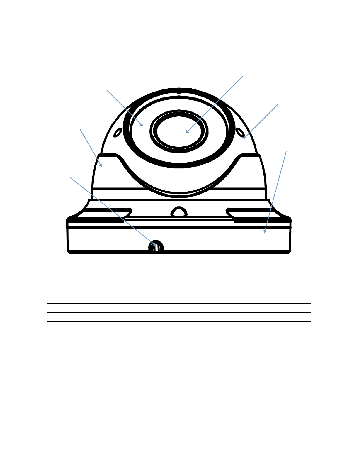
Model: EZ-IP642812IR
Items Descriptions
① Transparent cover
Protect the hemisphere
② Infrared lamp
Infrared LED lamp
③ Lens
Lens of camera
④ Black inner cover
Fix the hemisphere
⑤ Adapter disc
Connect tailing line and fix adjustment bracket
①
②
③
④
⑤
Page 9
8
Model: EZ-IP6236IR
Items Descriptions
① Lens
Lens of camera
② Infrared lamp
Infrared LED lamp
③ Hemisphere
It is rotatable and used to adjust the installation angle
④ Fixed guard
Fix the position of the hemisphere.
⑤ Base
Fix the device at the installation location.
⑥ Fixing hole
Fix with screws at t he installation location.
①
②
③
④
⑤
⑥
Page 10
9
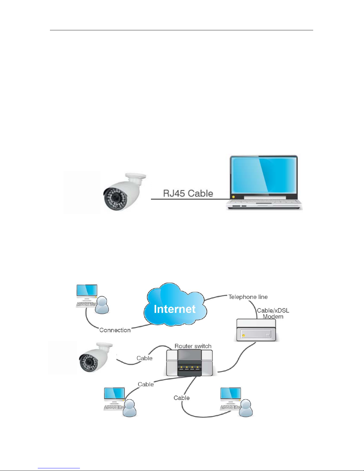
Device Connection
There are two types of connection:
1. Connect the device with PC
Connect IP camera with PC by network cable. The supply hub of IP camera is connected with
DC 12V power supply. Set the IP of PC and that of IP camera in the same network segment. If the
network is normal, wait for 1 minute after power on and IP camera will establish communictaion
with PC.
2. Connect the device with r out er or switchboard.
It the most commonly used w ay to connect IP came r a t o t he I nt er net . Connect IP camera and PC to
Lan Port on the router or switchboard and set the gateway of IP camera as that of the rout er.
Page 11

10
Device Search Tool
The software can detect the IP address of IP camera in the LAN.
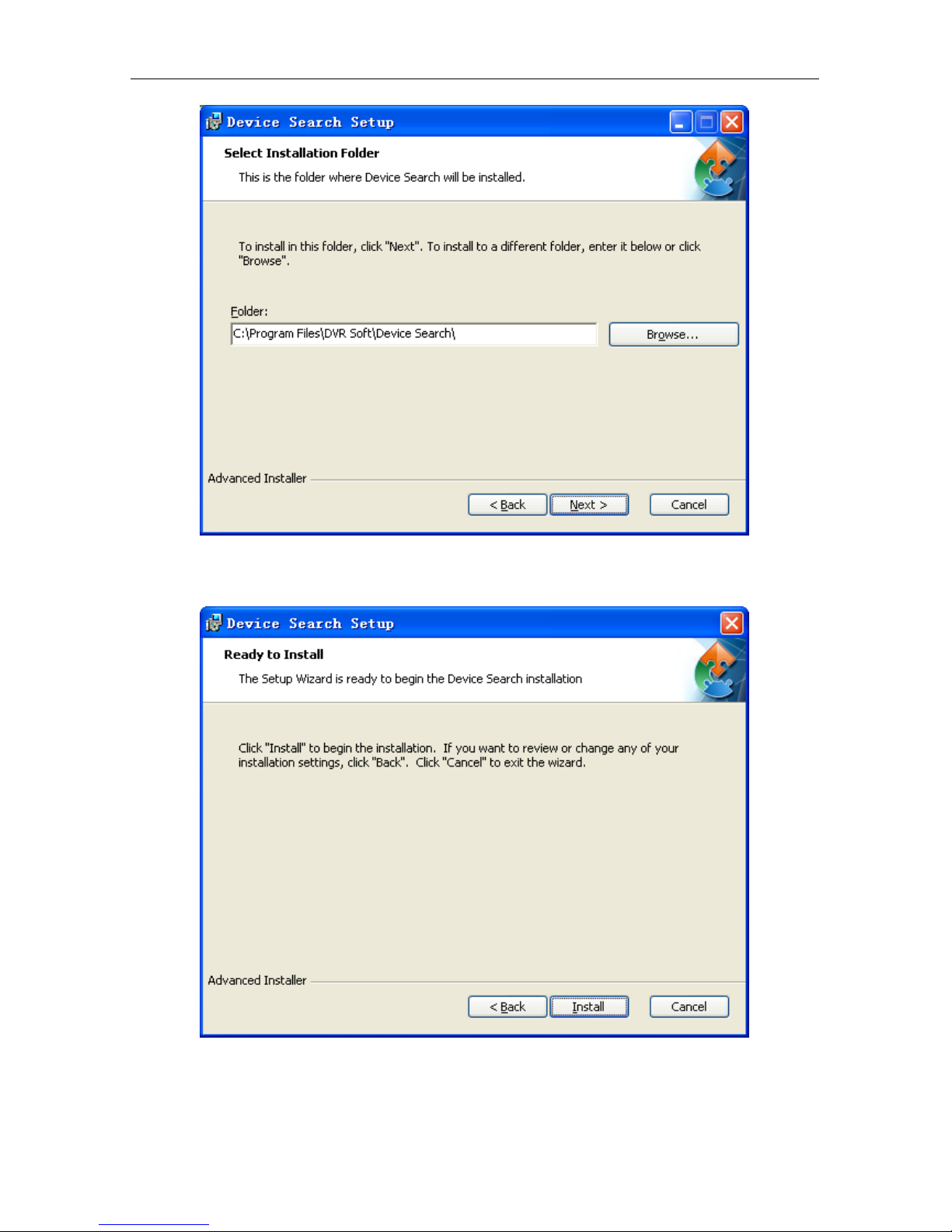
Firstly, install .exe file (Device Search) in the included CD by the following pr ocedures.:
1. Double click the .exe file
2. Click [Next] to continue.
3. Select installation folder and click [Next] to continue.
Page 12
11
4. Click [Install] t o begin the installation.
Page 13
12
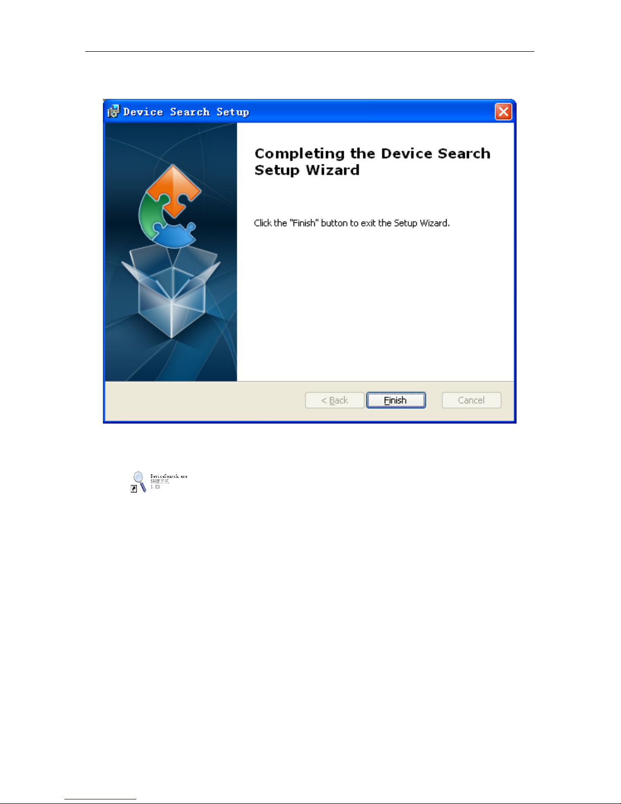
5. Click [Finish] to finish the installation.
Run the installed Devic e Sear ch.exe software.
Click to run the software and it will automatically display the IP address, subnet
mask, gateway, port, version information and MAC address of the running IP camera in the current
LAN, as shown in the following p ict ur e:
Page 14

13
If the searched IP address and PC IP address are not in the same network segment, user may
modify IP address, subnet mask, port number and other parameters of IP camera by using Device
Search software.
In the DeviceSearch software, select a device to modify IP address and then input new IP
address, subnet mask, gateway, port number and administrator password(default: admin). Click
【Modify】 to change IP address of the device, as shown in the fo ll ow ing picture:
Note:Def ault IP of IP cam era is “192.168.1.168”, username is “admin”, password is “admin” , and
Page 15

14
media port number is “9988”.
ActiveX Control Setup
If the user visits IP camera with Internet Explorer for the first time, he has to install the plug-ins.
For installing the plug-ins, it is necessary to set the browser security level. Enter menu
[Tools/Internet Options/Security/Custom Level] and change “ActiveX controls and plug-ins” as
“Enable” or “Prompt”, as shown in the fo llowing p ictu re. For safety, after you view the image of IP
camera, please reset the security setting in IE browser t o def ault level.
Installation method of p lug-in:
Input IP address of IP camera in IE address bar to visit IP camera. The controls will be
automatically loaded on I P camera.:
The plug-in installation dialogue box will be popped up. Click “Install” and the installation will be
completed automatically.
Page 16

15
Webpage Configuration of IP Camera
Live
Open Internet Explorer and input IP addres s of IP ca mera(http://192.168.1.168). The login
dialog box will appear. See the foll ow ing picture:
User may select stream ty pes and fluent level in the login interf ace.
Input user name(default: a dmin) and p assw ord (def ault: ad min) and clic k “ Login” t o enter the Liv e
interface, as shown in the follow ing picture.
Page 17

16
Other buttons on the Live interf ace:
:Enter the device settin g me nu a nd set custo miz ed par am eters o f the dev ice ;
:Snapshot, file type, st or age path, etc.;
:Log out and return to the login i nt er f ace;
:It shows preview control buttons. From the left to the right, the
names of buttons are play, stop, full screen, snapshot, start /stop recording, enable/disable talkback.
:Enable/d i sable sound; Open/close video set t ing.
Click “Local Setting” to pop up t he following dialog box:
User may set Record Path, Download Path, Snapshot Path, File Type and Interval for manual
recording.
Page 18

17
Parameter Setting
Display
Live
Click ,and enter the followi ng i nt er face(Live interface by default):
Channel Name:Name of I P camera
Channel Display:Enable or disable. It may customize the display location.
Time Display
:Enable or disable. It may custo m iz e the display location.
Flicker Control
:50HZ, 60HZ or disable
Transparency
:Set the transparency of OSD background color.
Page 19
18
Image Control
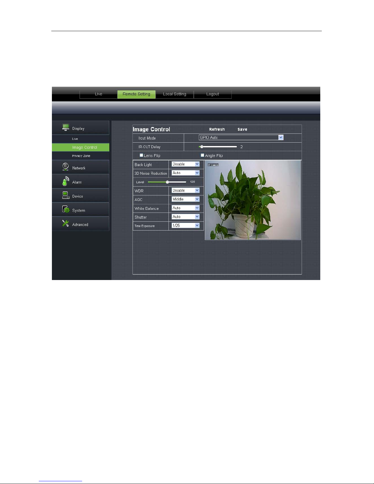
Click【Display】→【Image Contro l】to enter the following inter face.:
IRCUT Mode
:4 modes: GPIO Auto, Video Auto, Color Mode and Black & White Mode.
IR-CUT Delay
:Set IRcut delay switching tim e
Image flip
:Lens flip and angle flip
Back light
:Enable or disable the Back light. When enabled, there are three levels: low, middle and
high.
Back light compensation c an co mpens ate the dar kn ess o f the su bject caus ed by shoot ing aga inst the
sunlight. In some application scenario, the field of view may contain a very bright background field,
such as the door and window against the light, w hile the obse rv ed subject is sur rounde d by the bright
field. In this case, the photo is gloomy and has no layering. The backlight compensation can be
applied to solve the problem.
3D Noise Reduction
:Enable (auto or manual) or disabl e the v ideo no ise red uct ion funct ion. D efault
setting is Auto.
WDR
:Enable or disable WDR function.
WDR is a technology that enables the camera to catch the image features with strong contrast.
In short, DR (dynamic range) is the details of the bright part and dark part of image. The larger
dynamic range shows richer layers and broader color space.
Page 20

19
AGC:Adjust the level of AGC(low, middle and high)
White Balance:Auto, manual and indoor
Auto﹕Optimize according to the current lighting conditions and screen mode and calibrate
the video color of the camera.
Manual﹕Manually adjust red and blue gain of camera video
Indoor﹕Optimize according to the indoor environment and automatically calibrate the video
color of camera.
Shutter
:It has auto mode and manual mode. Default mode is Auto.
Time exposure
:Adjust exposure level of camera.
Privacy Zone
Click 【Display】→ 【Privacy Zone】 to enter the following interface:
Set privacy zone:
1. Click to enable privacy z one.
2. Press and drag left mouse button to select privacy zone (4 zones at maximum).
3. Click Save to make the priv acy zone effective.
Page 21

20
Delete:Click Refresh, se lect a pr ivacy zone, click Delete, and c lick Save. The zone will be deleted.
Network
Network Setting
Click【Network】→ 【Network Setting】to enter the following interfac e:
Type
:DHCP or Static. Default type is Static.
Client Port
:Client port of IPC
Web Port
:Web port of IPC
Mobile Port
:Connection port of mobile cl ient
IP address
:IP address of IPC
Subnet Mask: Subnet mask of IPC
Gateway
:Default gateway of device
DNS1/DNS2
:Configure DNS server
UPNP
:Enable or disable UPNP function of device.
Note :When UPNP is enabled, user has to set the client por t , web port and mobile por t in the range
Page 22
21
of 1024-65535. Client p ort is used for the con nection of self-dev eloped mobile cli ent; Mob ile port is
used for the connection of ASEE or ASEE+ cl ient.
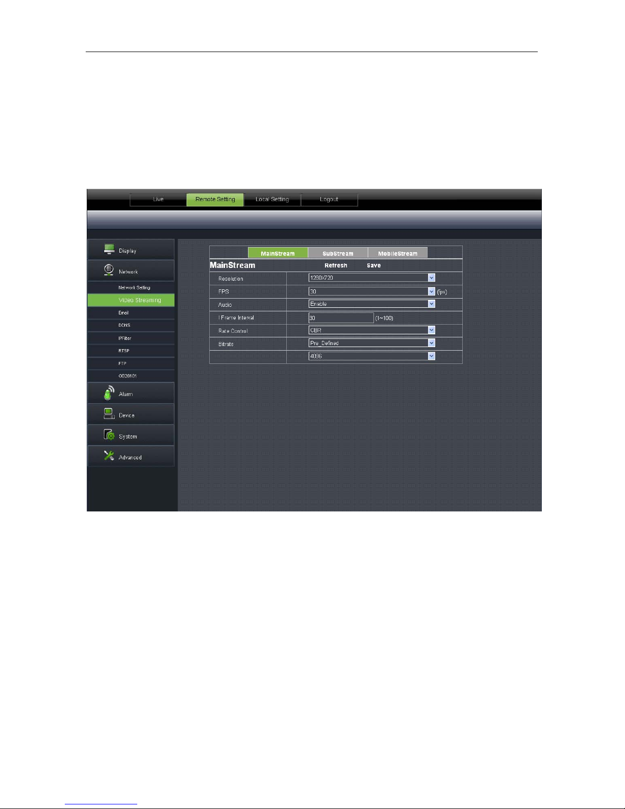
Video Streaming
Click【Network】→【Video Streaming】 to enter the following interface:
Type:Main stream, sub stream and mobile stream
User may set resolution, FPS, I Frame Interval, Rate control(CBR/VBR) and Bitrate of
Mainstream/Substream/Mobilestream.
Resolution
:mainstream(1280×720), substream(640×480), mobilestream(320×240)
FPS:When fl icker control is 5 0HZ,it can be set as 25 at maximum; When flicker control is 60HZ,
it can be set as 30 at maximum.
Audio
:Audio control switch for the st r eam
I Frame Interval
:Set I frame interval
Rate Control
:Set the rate as CBR or VBR
Bitrate
:Set bit rate as fixed value or pre-defined.
Page 23
22
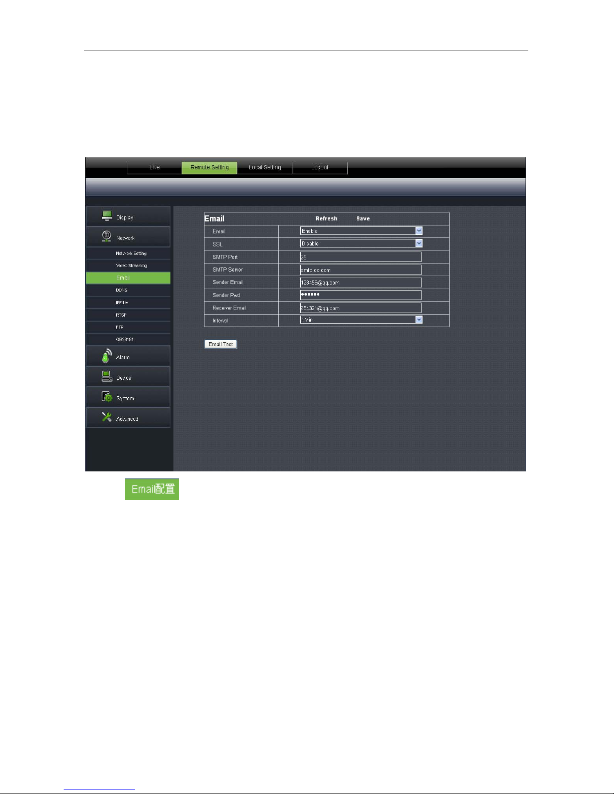
Email
Click【Network】→【Email】 to enter the following interface:
:Email service setting. Apply this function with alarm function and the images
captured during alarming can be uploaded to E-mail server through network.
Enable Email: Disable or enable
SMTP Port:Default value is 25(E-mail service
port)
SMTP Server:Input E-mail server address Sender Email:Sender’s Email address
Sender Pwd:Password of sender’s Email Receiver Email:Receiver’s Email address
Interval:Select interv al for sending Email(1min, 3m in, 5min, 10min)
Page 24

23
DDNS
Click【Network】→【DDNS】 to enter the following interface:
:It refers to Dynamic Domain Name Server, which is used together with
server for outer network accessing.
DDNS
:Enable Server :Select 3322
Host Name
:Input the host name User Name:User’s name
Password
:User’s password
Page 25
24
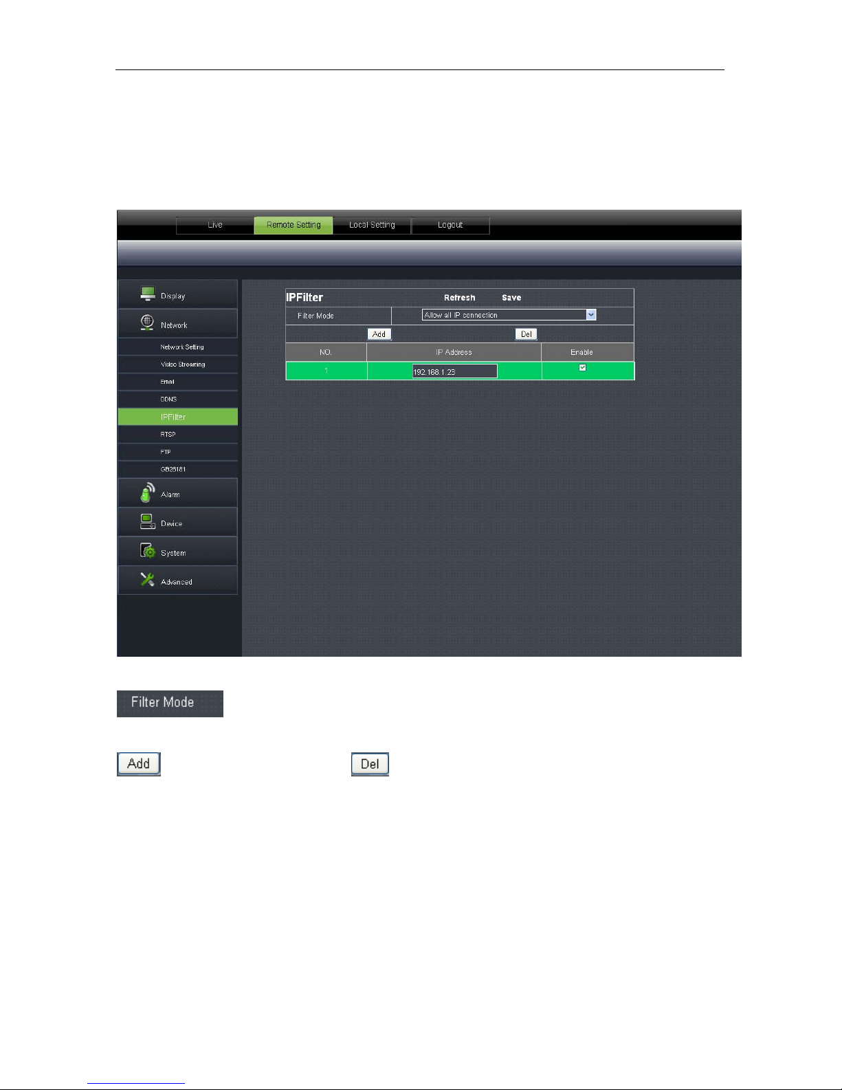
IP Filter
Click【Network】→【IP Filter】to enter the following inter f ace:
:Three modes: allow all IP connection, allow all set IP connection, and disable set
IP connection.
:Add allowed IP or disa bled IP :Delete added IP
Page 26
25
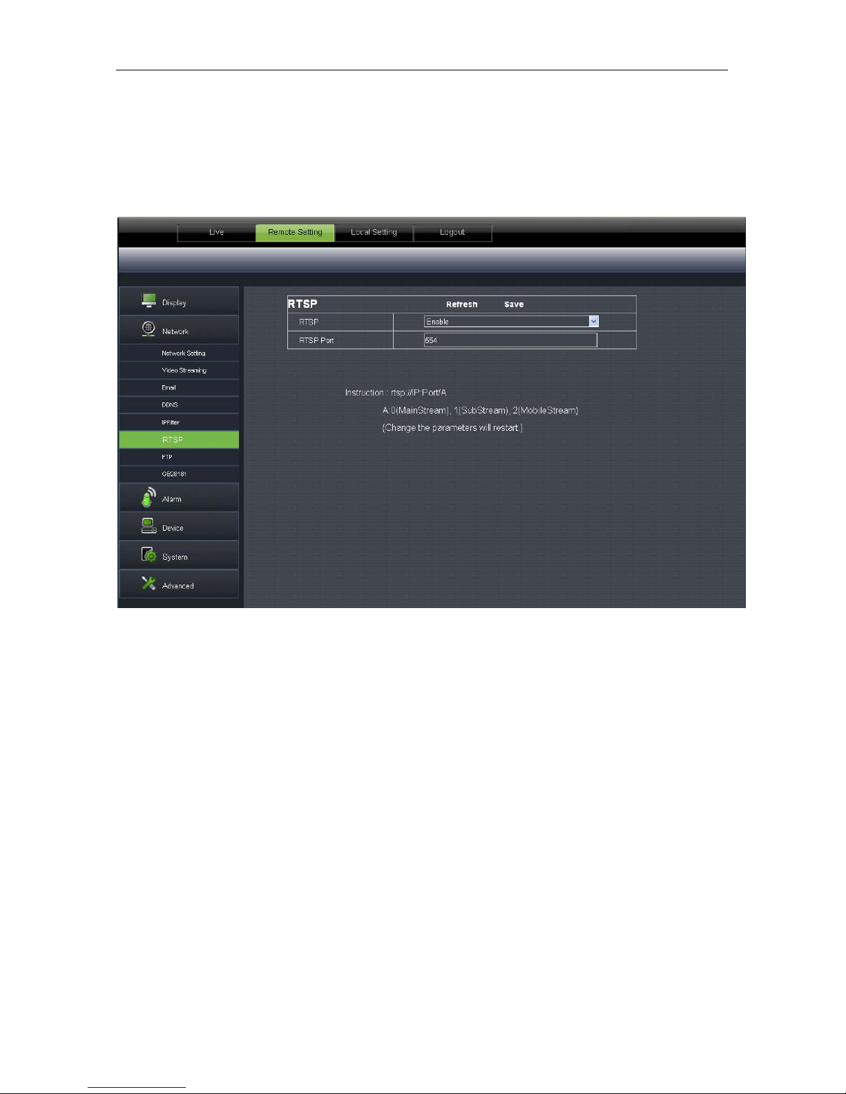
RTSP
Click【Network】→【RTSP】to enter the following interface:
RTSP:Enable or disable. Default setting is “Enabl e” . I f it is set as “Disa ble”, us er may not find t hroug h
ONVIF.
RTSP Port: Default value is 554. The value can be changed in the range of 1024-65535. After
modification, the device will be restarted.
Description
:
rtsp://IP:Port/A
IP: IP address of the device
Port:rtsp port of the device
A:0,1,2……,( 0 refers to main stream,1 refers to sub stream, 2 refers to mobile stream.)
Page 27

26
FTP
Click【Network】→【FTP】to enter the following int er fac e:
:FTP service setting. T his functi on is appl ied toget her with a larming f unction. The captur ed
images or alarming recording can be uploaded to FTP server through networ k.
FTP: Enable or disable
User Name:User name for visitingFTP assword:Password for visiting FTP
FTP Server:Input FTP serv er addr ess Port:FTP service port,def ault value is 21
Transfer Images:Click to transfer images Tran sf er Stream:Click to transfer stream
Page 28

27
GB28181
Click【Network】→【GB28181】to enter t he following interface:
The device supports GB28181 protocol. Click the option “Open and Effective” to enable the
function. Set related regist r at ion i nf ormation and click Save
Page 29
28
Alarm
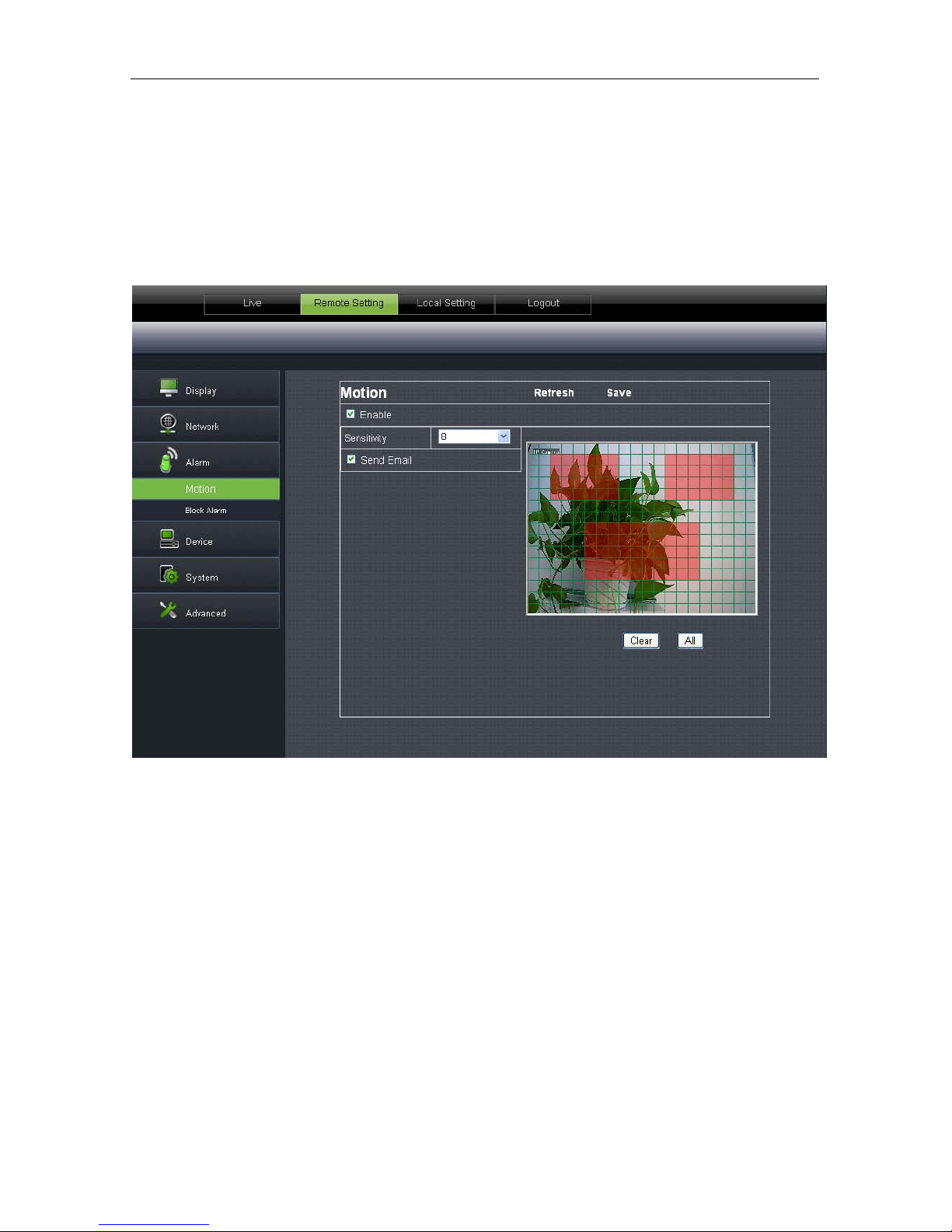
Motion
Click【Alarm】→【Motion】to enter the following interfac e:
Setting procedure
:
1. Click to enable motion detecti on.
2. Click and drag left mou se but t on t o select motion detection area.
3. Set motion detection sensit ivity(Range:1-8. Larger number indicates higher sensitivity.)
4. It can link SMTP to send by Email
5. Click Save to make the sett ing effective.
When the motion alarm is t r iggered, the screen on Live interfac e w il l appear green character “M”.
Page 30
29
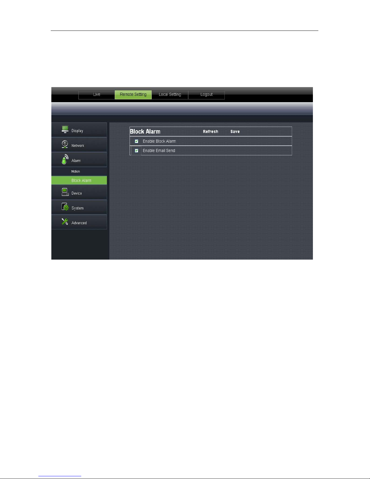
Block A larm
Click【Alarm】→【Block Alarm】to enter the following interface:
Alarm for blocking of camer a lens
It can link SMTP to send by Email.
Page 31
30
Device
It contains【Log】and【Audio】. Their interfaces and descriptions are as follows.
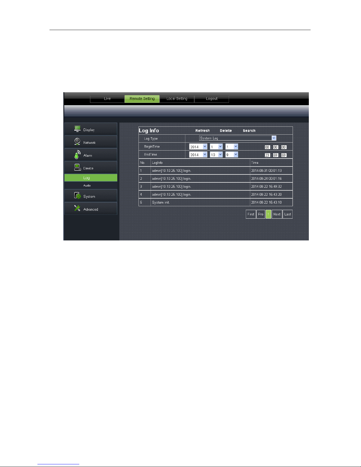
Log
Click【Device】→【Log】to enter the following inter fac e:
Log Type
:(system log, parameter log, alarm log, storage log, all log), totally 5 types for
selection. Set the begin time and end time of the sear ched log.
Click “Search” and t he corresponding log informat ion will be displayed below;
Click “Delete” and the device log will be r emoved;
Click “Refresh” and the selected log information will be refreshed.
Page 32

31
Audio
Click【Device】→【Audio】to enter the following inter fac e:
IPC audio switch
Audio setting pr oc edure:
Click “Enable Audio” and audio setting options appears. User may set the input volume and
output volume in the range of 0-10. After setti ng, click Save to save the changed parameters.
System
System includes【Date/Time】,【Users】and【Info】. Refer to the following description.
Page 33
32
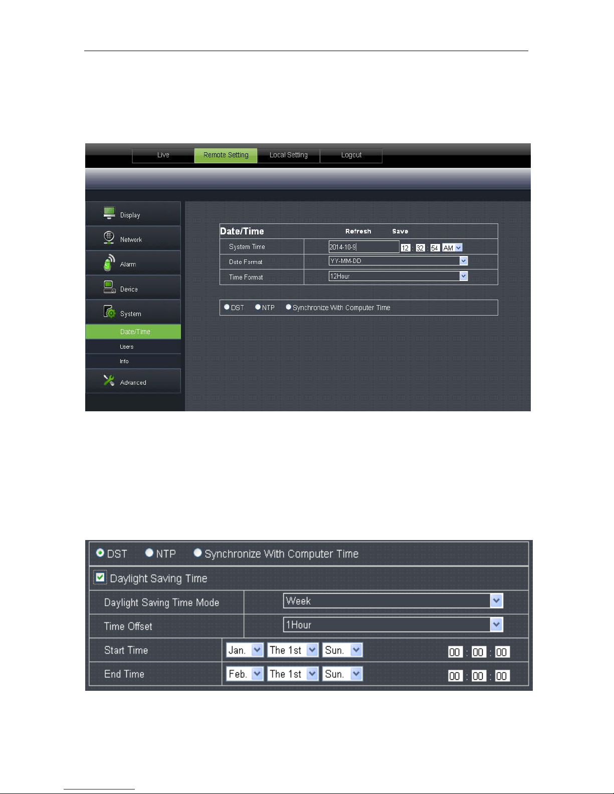
Date/Time
Click【System】→【Date/Time】to enter the follow i ng int erface:
In this interface, user may set Date/ Time, including Sy stem Time, Date Format and Time Format.
After setting, click Save.
The device also provides three kinds of automatic time synchr onization:
DST
:Click DST to enable DST function. The device will synchronize time according to the time
offset.
Page 34

33
NTP
:Synchronize time with NTP server. Click NTP to enable NTP setting. Input NTP server
address, select time zone and click Save. The system will automatically synchronize time with NTP
server.
Synchronize with computer time
:Device will take computer as the time server to synchronize
time.
Users
Click【System】→【Users】to enter the following interfac e:
Page 35
34
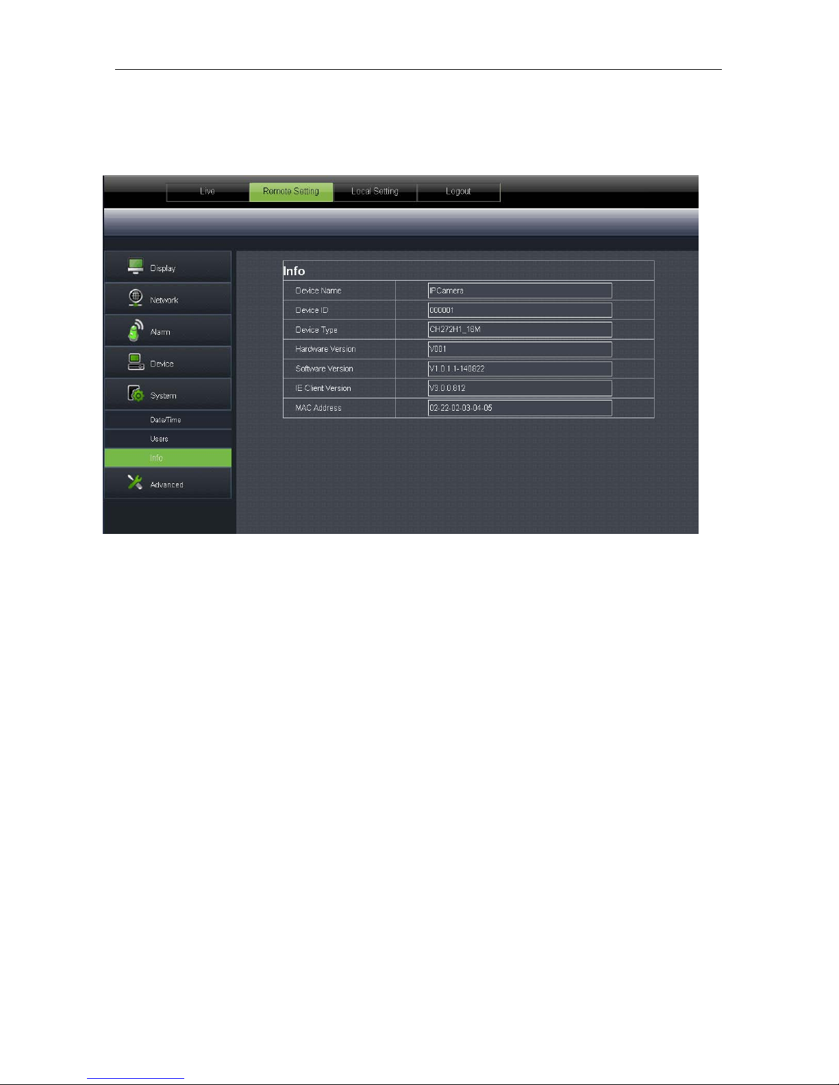
Info
Click【System】→【Info】to enter the following inter fac e:
It includes system information of the device, such as Device Type, MAC Address, Software Version,
etc.
Advanced
It includes【Firmware Update】,【Load Default】and【Maintain】, as shown in the following p icture.
Page 36

35
Firmware Update
Click【Advanced】→【Firmware Update】to ent er t he following interface:
In “Firmware Update” option, user may click “Scan” to select update file, click Upgrade button
and the system will be upgraded automatically. If the upgrade file does not match the device, the
update will fail.
Note
:It will take about 5 minutes to updat e the fir mw are. Do not cu t of f power or netw ork during
updating.
Page 37

36
Load Default
Click【Advanced】→【Load Default】to ent er t he following interface:
In “Load Default” option, click the corresponding options and click Save to restore factory
settings for the selected o pt ions.
Page 38

37
Maintain
Click【Advanced】→【Maintain】to enter the following interface:
In “Maintain” interfa ce, user may set periodically reboot or manual reboot.
Page 39

38
Technical Parameters
Items
Descriptions
100W 130w 200w
Camera
Image Sensor CMOS Sensor
Video Format P/N adaptive control
Minimum luminance
0.08Lux @(F1.2,AGC ON) ,
0 Lux with IR
0.03Lux @(F1.2,AGC ON) ,0 Lux with IR
Shutter speed
1/25s ~ 1/20,000s
Day/night switch mode IR auto switch
Compression
Standard
Video compression standard H.264
Video compression rate 64kbps-8Mbps
Triple stream Yes
Image
Max. r es ol ut io n 1280×720 1280×960 1920×1080
Image frame rate
50 Hz:
720P/25fps(1280×720
)
VGA/20fps
(
640×480)
QVGA/5fps(320×240)
60 Hz:
720P/30fps (1280×720
)
VGA/20fps
(
640×480)
QVGA/5fps(320×240)
50 Hz:
960P/25fps(1280×960
)
VGA/20fps
(
640×480)
QVGA/5fps(320×240)
60 Hz:
960P/30fps(1280×960
)
VGA/20fps
(
640×480)
QVGA/5fps(320×240)
50 Hz:
1080P/25fps(1920×1080
)
VGA/20fps
(
640×480)
QVGA/5fps(320×240)
60 Hz:
1080P/30fps(1920×1080
)
VGA/20fps
(
640×480)
QVGA/5fps(320×240)
Image Image setting Adjust saturation, brightness and contrast through client software of web browser.
Network Protocol
TCP/IP、UDP、RTP/RTCP、RTSP、HTTP、SMTP、DNS、DDNS、DHCP、FTP、NTP、PPPOE、UPNP
Port Data interaction port 1 RJ45 10M / 100M Ethernet interface
General
Specifications
Grade of waterproofing IP66
Working environment -10 °C ~ 60 °C (14 °F ~ 140 °F) below 90%RH(no condensation)
Power supply 12 VDC ± 10%, PoE
Page 40

39
Appendix 1Router Port Forwarding
If user wants to remotely visit I P Camera monitoring image t hr ough internet, he has to open web
port and client port of IP Camera.
Take Cisco router as an example:
IP address of IPC is 192.168.1.168, web port is 8000 and client port is 9988.。
Page 41

40
Appendix 2FAQ
◆ IE cannot loa d and install plug-ins.
Possible cause:IE security level is set too high.
Solution:Set IE security level to the minim um level.
◆ Aft er up dating, user cannot visit IP Camera through IE.
Solution:Clear IE cache. Specific steps: Open IE Tools, open Internet option, click “delete file”
button in the 2
nd
option (temporary Internet files), click “delete all offline contents”, and click OK.
Log in IP Camera again.
◆ Why cannot visit IP Came r a through IE?
Possible cause 1:Network fault
Solution:Connect PC to internet and test if network access is normal. Check if there are any
cable problems or networ k problems caused by PC v ir us unt il PC can ping each other.
Possible cause 2:IP ad dress is occupied by other devices.
Solution:Disconnect IP c amera and networ k and conne ct IP C and PC and set dev ice IP addr ess.
Possible cause 3:IP ad dress is located in dif ferent subnet.
Solution:Check setting of IP addr ess, subnet mask address, and gateway.
Possible cause 4:The physical address of the networ k conflicts with IP camera.
Solution:Change physical address o f IP camera.
Possible cause 5:Web port is changed.
Solution:Contact network ma nagement to obtain t he cor r esponding port information.
◆ PC client c annot be connected to the frontend video
Solution:Check if IP camera video can be nor mally viewed i n IE, if th e device can be se arched by PC
client software, and if the device parameters on PC client are set correctly.
◆ Mobile client cannot be connected to the frontend video
Possible cause 1:Mobile stream is not enabled
Solution:Enable mobile stream.
Possible cause2:Mobile por t number is not input correctly.
Solution:The port number of our mobile client software is 9988 and that of the third-party clien t is
8800.
Possible cause3:Device video streams connection s excee d the maxi mum limit ati on.
Solution:Reduce the connections o f dev ice video streams.
 Loading...