

Page 1
Installation & Parts Manual
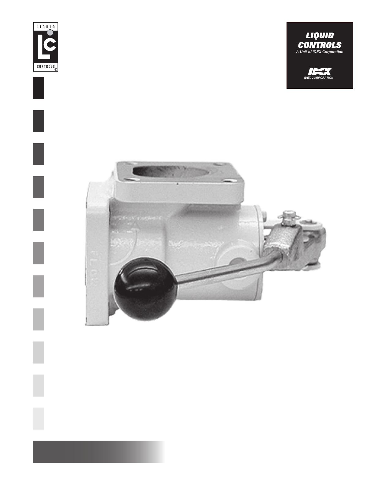
V-7 Valves
Installation: M400-10
www.lcmeter.com
Page 2
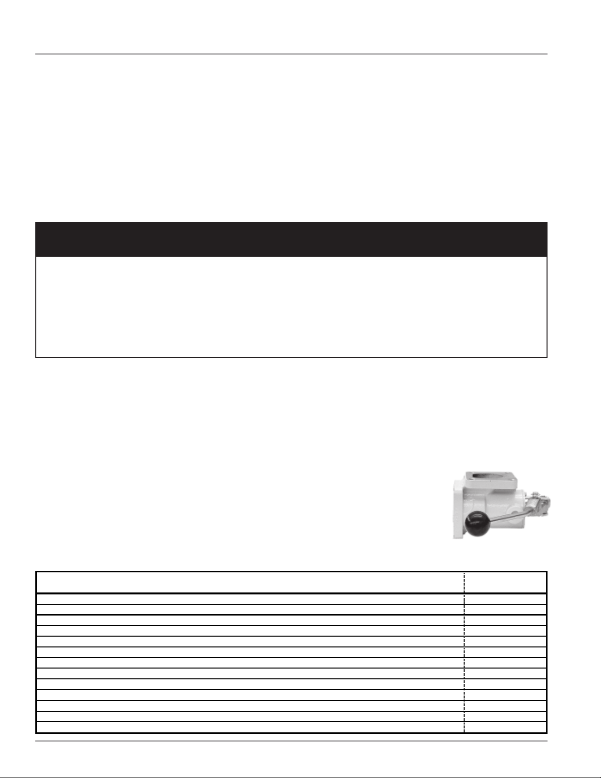
Table of Contents
Description Page Number
General Information ...............................................2
Application Class Description ................................2
Specifications .........................................................3
How V-7 Valves Work.............................................3
Accessories............................................................4
New Installations ....................................................5
Retrofit Installations ...............................................5-7
Setting the Dwell ....................................................8
Setting Zero Shut-off ..............................................9
Disassembling........................................................10-11
Reassembling ........................................................11
Illustrated Parts Breakdown ...................................12-15
!!
! WARNING
!!
• Before using this product, read and understand the instructions.
• Save these instructions for future reference.
• All work must be performed by qualified personnel trained in the proper application, installation, and
maintenance of equipment and/or systems in accordance with all applicable codes and ordinances.
• Failure to follow the instructions set forth in this publication could result in property damage, personal injury,
or death from fire and/or explosion, or other hazards that may be associated with this type of equipment.
Publication Updates and Translations
The most current English versions of all Liquid Controls
publications are available on our website,
www.lcmeter.com. It is the responsibility of the Local
Distributor to provide the most current version of LC
Manuals, Instructions, and Specification Sheets in the
required language of the country, or the language of the
end user to which the products are shipping . If there
are questions about the language of any LC Manuals,
Instructions, or Specification Sheets, please contact your
Local Distributor.
General Information
Liquid Controls V-7 Valves are designed for a wide range
of applications and flow rates and have minimum
pressure loss. Careful engineering and construction
ensure smooth, accurate, and controlled operation.
The V-7 Series mechanically actuated piston valves are
available in 1½” and 2” sizes, and are designed for
mounting on the meter outlet to provide tight shut-off with
smooth and easy operation regardless of system line
pressure. The valves may be manually operated or
connected via a mechanical linkage to a preset counter
on the meter for singe-stage closure (for low flow
applications) or two-stage closure with dwell period to
eliminate hydraulic shock. The valves are indexible in
90º increments for up, down, or side facing outlet.
Applications Class Description
Refined petroleum products 1
Aviation and jet fuel 2
Variety of products including: liquid sugars, sweeteners, syrups, & vegetable oils 3
Treated waters & solvents where no red metals are allowed 4
Chlorinated solvents 7
Acidic pH liquids including: nitric, phosphoric, glacial acetic acids, citric juices, & vinegar 8
Crude Oil 14
Oil-based & Water-bases latex products, polyester, resins, herbicides, & nitrogen fertilizers 15
General Solvents, 200 proof alcohol 16
Batch process water meter service 20
Alkaline pH Liquids including: latex products, adhesives, & liquid fertilizers 27
Herbicides 30
Sodium Hydroxide solutions, high sulfur crude oil, & alkaline pH liquids 37
V-7 Series valves offer the important advantage of a
pressure-balanced dashpot design that ensures precise
valve response and soft closure at shut-off. Operation is
smooth and easy regardless of the line pressure since
the vector forces are directed at right angles to the valve
opening mechanism and are never in opposition to it.
Depending on the preset, the
valve may be operated as either
a two-stage valve with dwell
period shut-off or as a singlestage valve with abrupt shut-off.
Single stage valves are
recommended when the
application flow rates are low.
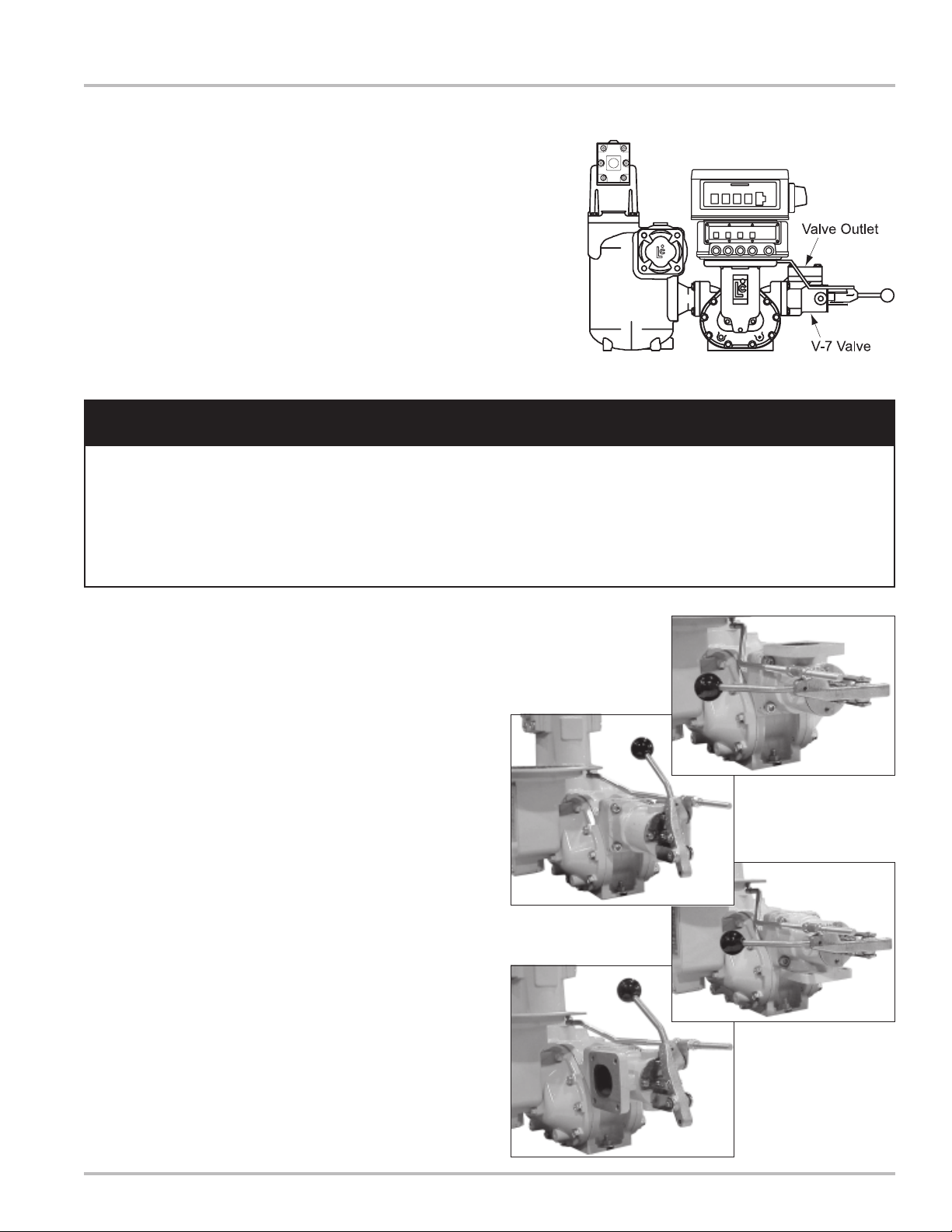
Figure 1: V-7 Valve
Class
Number
2
Page 3
Specifications
Model
V-7 (A2600 Series)
Used with M-5, M-7 & M-10 Meters
A2621 1½" & 2" 1, 2, 14
A2623 1½" & 2"
A2631 1½" & 2" 1, 3, 14, 15
A2651 1½" & 2" 3, 4, 14, 15, 16
A2652 1½" & 2" 1, 2, 16, 20
A2655 1½" & 2" 1, 30
A2684 1½" & 2" 20
A2690 1½" & 2" 20
A2693 1½" & 2" 20
A2670 1½" & 2" 7, 37
A2671 1½" & 2" 7, 27
A2672 1½" & 2" 7, 27, 37
A2681 1½" & 2" 8
A2682 1½" & 2" 8
Body & Seal Material
Aluminum with Viton Seal
Aluminum with Teflon Seal
Aluminum with Viton Seal
Aluminum with Viton Seal
Aluminum with Buna N Seal
Aluminum with Viton & Teflon Seal
Brass with Viton Seal
Brass with Viton Seal
Brass with Teflon Seal
Cast Iron with Viton Seal
Cast Iron with Teflon Seal
Cast Iron with Viton Seal
Stainless Steel with Viton Seal
Stainless Steel with Teflon Seal
Companion
Flanges
Working
Pressure
150 PSI
(10.3 BAR)
150 PSI (10.3 BAR)
150 PSI (10.3 BAR)
150 PSI (10.3 BAR)
150 PSI (10.3 BAR)
150 PSI (10.3 BAR)
150 PSI (10.3 BAR)
150 PSI (10.3 BAR)
150 PSI (10.3 BAR)
150 PSI (10.3 BAR)
150 PSI (10.3 BAR)
150 PSI (10.3 BAR)
150 PSI (10.3 BAR)
150 PSI (10.3 BAR)
150 PSI (10.3 BAR)
Application
Class*
1, 2, 3, 4, 14, 15,
16, 30
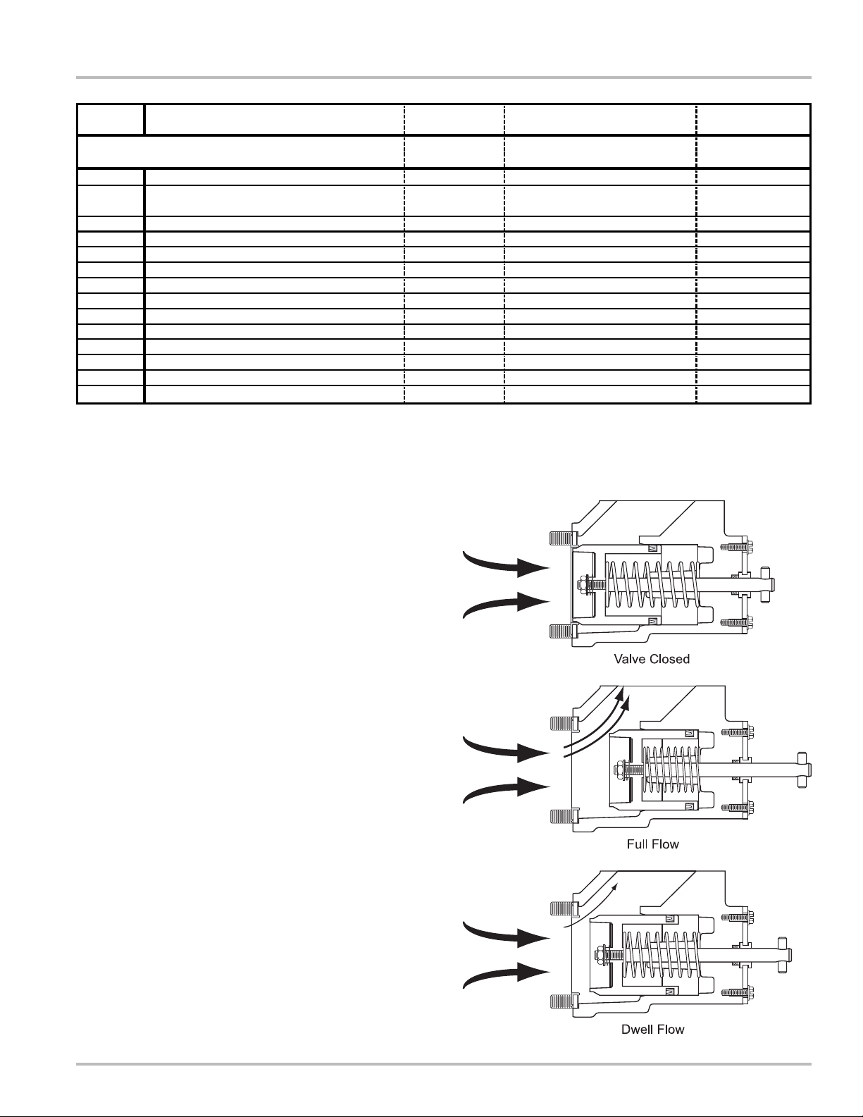
How V-7 Valves Work
Inside the valve housing, a cylindrical bore connects the
valve inlet and outlet. Contained within the bore is a
piston assembly. Measured liquid exiting the meter outlet
is blocked from entering the valve inlet by the piston and
seal.
As the meter operator shifts the handle to the open
position, a mechanical linkage connecting the valve to
the preset counter trip ring causes a latch to engage and
hold the valve open allowing liquid to flow.
In the open position, the valve handle assembly
compresses the piston spring and pulls the piston shaft
and the piston away from the valve inlet. As the piston is
pulled away, it disconnects from the inlet seal, allowing
liquid to flow.
In most metering applications, closing the valve is a twostage process. At a predetermined dwell period, the
preset counter, while counting down to “0”, releases a
latch mechanism, allowing the valve linkage to close to
approximately 10% of full flow. This initial closing causes
the piston inside the valve to slide toward the inlet,
restricting product flow.
As liquid is blocked by the piston, some product passes
through the dashpot washer bleed holes, creating the
hydraulic balance feature of V-7 Valves that allows the
valve to close slowly and smoothly. The dwell period
prevents hydraulic shock while permitting the preset
counter to register the remaining flow.
As the preset counter reaches “0”, the preset counter trip
ring disengages from the dwell position to the fully closed
position. This action releases the valve handle and relaxes
the piston spring, permitting the piston to contact the inlet
ring seal and complete its closure, stopping product flow.
This process is illustrated in Figure 2.
Figure 2: Valve Operation
3
Page 4
V-7 Valves
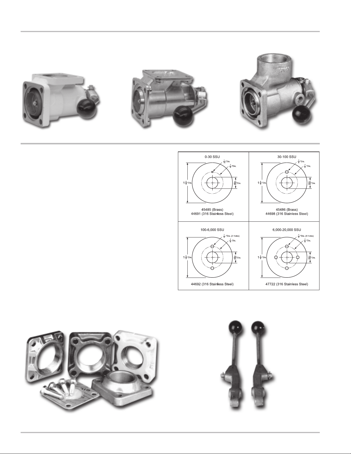
Figure 3a: Cast Iron or Aluminum
Accessories
Dashpot Washers
V-7 Valves are offered with a variety of dashpot washers.
They are available in either brass or stainless steel
construction material. Four different bleed orifice
configurations (Figure 4) are available to ensure proper
closure regardless of viscosity. For viscosities greater
than 20,000 SSU, do not use a dashpot washer.
Flanges
Flanges (Figure 5) are offered in 1½ and 2 inch BSPT
and NPT sizes and weld types. Materials of construction
are aluminum, brass, cast iron, and stainless steel.
Teflon, Viton, and Buna seals and gaskets are available.
Linkage and Valve Handles
Valve handle (Figure 6) and linkage assemblies are
accessories used when normal manual ON and OFF
valve operation is desired. Different handle and linkage
configurations can be ordered separately for field
installations.
Figure 3c: BrassFigure 3b: Stainless Steel
Figure 4: Dashpot Washers
Figure 6: Left and Right Valve HandlesFigure 5: Flanges
4
Page 5
New Installations
When ordered with a new metering system, the V-7
Series Valve is supplied mounted to the outlet side of the
meter as shown to the right. A liquid line must be
connected to the flange on the outlet side of the valve or
to the accompanying air check valve. The flange
connection on the V-7 valve is 1½” or 2” BSPT or NPT or
weld type.
!!
! WARNING
!!
Relieve Internal Pressure
All internal pressure must be relieved to zero pressure before
disassembly or inspection of the meter or any of the meter accessories.
V-7 Valves - Installation
Figure 7: V-7 Valve installed
Serious injury or death from fire or explosion could result from
maintenance of an improperly depressurized and evacuated system.
Retrofit Installations
Depending on the existing configuration, adding a V-7
Valve may require modification of the outlet piping.
After the internal pressure is relieved from the system,
the outlet line can be disconnected from the meter. The
new valve assembly can then be connected to the outlet
side of the positive displacement meter.
Installing the Valve
V-7 valves can be mounted in four possible positions
(Figures 8a-8d) depending on the required direction of
the valve output. The output can be front or back, top or
bottom. Standard valve position is configured with a top
outlet connection for flow from left to right and a horizontal
handle with an offset linkage assembly.
Positioning the Seal Ring
Each V-7 Valve is supplied with a seal ring. The inner
seal lip faces the valve housing and not the meter. Place
the seal on the valve and mount the valve to the meter
using the four bolts provided. Thread the four bolts into
the meter housing but do not tighten.
Figure 8a:
Standard Top
Facing Outlet
Figure 8b: Rear
Facing Outlet
Figure 8c:
Bottom Facing
Outlet
Figure 8d: Front
Facing Outlet
5
Page 6

V-7 Valves - Installation
Retrofit Installations (continued)
Attaching the Valve Handle
There are several options for valve handles. Systems
which do not use a preset use a faucet valve kit (Part
Number A2755).
For systems which use a preset, curved valve handles
are offered for left-to-right or right-to-left flow, or a straight
handle may be used. The valve handle options are listed
in the table below.
1. Line up the hole in the valve handle with the holes in
the lift bracket.
2. Insert the valve handle shaft through the lift bracket
and valve handle. Secure with one retaining ring on
each side of the lift bracket.
3. Insert the roller chain link into the valve shaft and
valve handle.
4. Slide the flat link over the ends of the roller chain
link. Secure the roller chain link with the retaining
clip.
The valve piston should be flush or slightly drawn into
the valve to ensure proper installation. Use a screwdriver
handle (Figure 10) or a wooden dowel to prop the valve
handle in the open position. This action will compress
the piston spring, drawing the piston into the housing
and allowing the valve to mount flush to the meter. With
the valve propped open, tighten the four bolts in crossing
pattern.
Figure 11 shows the valve handle mounted two different
ways. The valve on the left is opened by pulling on the
handle, the valve to the right by pushing on the handle.
Regardless of the valve or handle orientation, the link
pivot stub must face up in order to properly install the
linkage assembly.
Figure 9: Valve Handle Views
Figure 10: Handle Propped Open
Figure 11: Handle Orientations
V-7 Valve Handles for Aluminum, Brass, & Cast Iron Valves
Part Number Description
43614 Valve Handle Assembly, Curved, Right-to-Left Flow
43617 Valve Handle Assembly, Curved, Left-to-Right Flow
44685 Valve Handle Assembly, Straight
V-7 Valve Handles for Stainless Steel Valves
Part Number Description
46335 Valve Handle Assembly, Straight
45336 Valve Handle Assembly, Curved, Right-to-Left Flow
45337 Valve Handle Assembly, Curved, Left-to-Right Flow
6
Page 7

Installing the Linkage Assembly
Linkage assemblies are used with presets. The linkage
provides the connection between the valve handle and
the preset trip ring mounted on the mechanical register.
V-7 Valves - Installation
The linkage assembly is selected based on the meter/
register configuration. Linkage assemblies are available
in either straight or offset styles. These are listed in the
table below.
1. Mount the linkage assembly to the preset ring by
threading the threaded end of the ball joint into the
preset ring. Attach the linkage end to the ball joint
(Figure 13a).
2. Mount the other end of the linkage assembly to the
valve handle. Remove the retaining ring from pivot
stud on the valve handle to accomplish this.
3. Place the linkage bracket over onto the pivot stud
ensuring that the flat side of the linkage bracket is
facing the valve handle (Figures 13b & c). Secure
using the retaining ring.
Proceed with setting the dwell.
Figure 12: Linkage Assemblies
Ball Joint
Figure 13a
Figure 13b
Figure 13d: Linkage Installed
V-7 Valve Linkage Assemblies for Aluminum, Brass, & Cast Iron Valves
Part Number Style Description
49925 Offset For use on M-7 meters with TVC & V-R Preset
A2712 Straight Linkage Assembly for LC Preset
A2714 Offset Linkage Assembly for LC Preset
A2728 Offset Right-to-Left Flow with TVC & LC Preset
A2730 Straight For all Meters with a Counter Extension & LC Preset
V-7 Valve Linkage Assemblies for Stainless Steel Valves
Part Number Style Description
49922 Offset Stainless Steel for use with M-5 & M-7 Meters with V-R Preset
A2725 Straight Stainless Steel Linkage Assembly for LC Preset
A2726 Offset Stainless Steel Linkage Assembly for LC Preset
Figure 13c:
Retaining Ring
& Pivot Stud
7
Page 8

V-7 Valves
Setting the Dwell
Correct linkage adjustments avoid hydraulic shock.
Hydraulic shock occurs when a volume (mass) of liquid
moving at a high rate through a pipeline is stopped by a
valve that is suddenly closed. When the flow stops
abruptly, the mass of liquid acts as a battering ram,
causing a shock effect within the metering system. The
meter housing and internal parts receive the full impact
since the valve is located at the meter outlet. The greater
the mass, length of pipeline or velocity, the greater the
hydraulic shock and the greater the damage possibilities.
To prevent damage from hydraulic shock, a slow closure,
two-stage valve and preset should be used with the meter.
In some instances, mass, length of pipeline, or velocity
are of such a magnitude that using a two-stage valve is
ineffective. In this case, an impact absorbing, air
cushioning device should be used as an added
accessory.
The linkage between the valve and preset can be
adjusted to increase or decrease product flow during the
dwell period. To make adjustments shift the valve handle
to the slow flow or dwell setting. (See the preset counter
manual for more detail).
Figure 14: Linkage Adjustment
Turn the two 9/16 inch linkage nuts (Figure 14) located
on either side of the bracket to adjust the linkage for
proper dwell.
• On a right to left flow meter the nuts are moved to
the right to increase dwell flow and moved to the left
to decrease dwell flow.
• On a left to right flow meter the opposite is true.
Moving the nuts to the right decreases dwell flow
and moving nuts to the left increases dwell flow.
While adjusting the nuts, it is important to hold the linkage
rod firmly so that it does not move.
Proper adjustment is obtained when the far right wheel
of the preset counter (Figure 15) slows to a readable
rate and the characteristic dwell hiss is heard. Dwell
hiss is a low, resonating sound caused by slow moving
product through the valve.
When this is accomplished, tighten the adjusting nuts
ensuring that the linkage bracket is free to move, but
there is little slop between the linkage bracket and the
adjusting nuts.
Figure 15: Preset Counter
8
Page 9

Adjusting Zero Shut-off (LC Preset)
Because of the interaction between the valve and the
preset counter, some adjustment may be needed to the
preset counter so that components work at optimum
efficiency. Preset Counters assembled with meters at
the factory are adjusted for proper shut-off timing. Due
to meter system variations, such as flow rate and
viscosity, it may be necessary to make zero shut-off
adjustments.
At least two test runs should be completed before any
adjustments are made. On all presets, make a test run
using a value large enough to permit the meter to reach
its normal flow rate. If it is determined after testing that
an error in zero shut-off is indicated, correct the zero
shut-off in the following manner.
1. Start by removing the eight screws that hold the bezel
to the preset counter.
2. Remove the bezel (Figure 16a).
V-7 Valves
Figure 16a: Bezel Removal
3. Press the preset button directly below the units wheel
until the set screw appears in the opening.
4. Use a screwdriver to loosen the set screw on the
notch ring located on the left side of the units wheel
(Figure 16b). This allows for the repositioning of the
notch ring and units wheel.
5a. Early Shut-off
To correct an early shut-off, hold the notch ring in
place (Figure 16c) and move the numbers wheel
down enough to correct the misalignment.
5b. Late Shut-off
To correct a late shut-off, hold the notch ring in place
(Figure 16c) and move the numbers wheel up enough
to correct the misalignment.
6. After each adjustment, carefully tighten the set screw.
Take care not to strip the threads with excessive
torque.
7. After running two test runs, the zero should be
centered in the window. If not, reset the notch ring
and repeat the procedure.
Figure 16b: Set Screw & Notch
Ring
8. Ensure that the set screw is tight and remount the
bezel.
Figure 16c: Set Screw Adjustment
9
Page 10

V-7 Valves
Disassembling the Valve
!!
! WARNING
!!
Relieve Internal Pressure
All internal pressure must be relieved to zero pressure before
disassembly or inspection of the meter or any of the meter accessories.
Serious injury or death from fire or explosion could result from
maintenance of an improperly depressurized and evacuated system.
To perform maintenance on a V-7 valve, or to repair a V7 valve, it must be removed from the meter. Note the
orientation of the valve so that it can be replaced in the
proper orientation. Drain all the fluid from the metering
system prior to valve removal.
1. Remove the four screws and washers holding the
valve to the meter.
2. Remove the valve from the piping connection.
NOTE: The valve piston is under pressure exerted by
the valve compression spring. Exercise caution when
disassembling the valve.
3. Place the valve on a flat surface with the valve piston
facing down (Figure 17a).
4. Remove the retaining clip from the connection link.
A screwdriver may be needed to pry the retaining
clip off (Figure 17b).
5. Press down on the valve housing so that the valve
piston is forced into the valve, pushing the valve shaft
and handle away from the valve housing.
6. While keeping pressure on the valve, remove the
two pieces of the connection link (Figure 17c-d).
7. Slowly release the valve until the compression spring
exerts no pressure. As the valve housing is lifted,
the piston assembly and compression spring should
easily slide out of the housing (Figure 17e). The
piston and seals may now be inspected, cleaned and
replaced as needed.
Figure 17a
Figure 17b
Figure 17c
Figure 17e: Piston Assembly Removed
10
Figure 17d
Page 11

Disassembling the Valve (continued)
Disassembling the Piston Assembly
8. Use a 7/16” wrench to remove the nut from the valve
shaft (Figure 18a).
9. Remove the nut, washer, spring, dashpot washer,
and piston from the valve shaft (Figure 18b).
Reassembling the Valve
1. Place the piston on the valve shaft.
2. Place the dashpot washer, spring, and washer on
the valve shaft and secure by placing the nut on the
end of the valve shaft.
V-7 Valves
3. Place the compression spring into the valve housing.
4. Insert the valve shaft and piston assembly into the
valve housing. The piston will rest on the
compression spring.
5. Place the assembly on a flat surface with the piston
facing down.
6. Press down on the valve housing, compressing the
compression spring and forcing the end of the valve
shaft to protrude out of the valve housing.
7. While keeping pressure on the valve assembly, insert
the link connector through the valve shaft opening
and the valve handle opening.
8. When the link connector in completely inserted
through these two elements, place the flat end of the
link connector over the two studs and secure with
the retaining clip.
When reassembly of the V-7 valve is complete, it may be
returned to service. Follow the installation instructions
which begin on Page 5.
Figure 18a: Piston Assembly
Figure 18b: Piston Assembly Disassembled
11
Page 12

Illustrated Parts Breakdown - V-7 Aluminum Valves
A2655 Shown
Item No. Description Part No.
110 Valve Housing 43605
133 Piston 43607
220 Piston Sub-Assembly 49808
318 Lift Bracket 43652
337 Roller Chain Link 07103
354 Lower Seal Ring 43626
370 Valve Shaft 43612
380 Dashpot Washer Spring 43620
382 Compression Spring 43678
453 O-Ring (2) 09275
465 Quad Ring, Viton 07832
516 Sleeve Bearing 07102
532 Self Locking Nut 06050
553 Valve Handle Shaft 45345
564 Retaining Ring (2) 07304
572 Retaining Ring 06044
606 Screw, #10-24 x .625 (4) 09079
626 Screw, .375-16 x 1.25 (4) 06991
724 Flat Washer 06635
727 Dashpot Washer (See Page 4)
738 Flat Washer (4) 04607
Model
Num be r
It e m No. Par t No .
110
133
220
318
337
354
370
380
382
388
424
446
453
465
516
532
553
564
572
606
626
724
738
780
A2621 A2623 A2631 A2651 A2652 A2655
43605 44695 43605 43605 43605 43605
44658 43607 43602 43602 43602 43607
N/S 4980 8 N/S N/S N/S 49808
43652 43652 43652 43652 43652 43652
07103 07103 07103 07103 07103 07103
43626 43674 43626 43626 43608 43626
43612 43612 43612 43612 43612 43612
43620 43620 N/A 43620 43620 43620
N/A 43678 43678 43678 43678 43678
N/A 0694 3 N/A N/A N/A N/A
N/A 4581 8 N/A N/A N/A N/A
N/A 4469 6 N/A N/A N/A N/A
09275 N/A 09275 09275 07443 09275
07822 07832 07253 07253 06848 07832
07102 07102 07102 07102 07102 07102
06050 06050 06050 06050 06050 06050
45345 45345 45345 45345 45345 45345
07304 07304 07304 07304 07304 07304
N/A 0604 4 N/A N/A N/A 06044
09079 09079 09079 09079 09079 09079
06991 06991 06991 06991 06991 06991
06635 06635 N/A 06635 06635 06635
04607 04607 04607 04607 04607 04607
N/A 4367 2 N/A N/A N/A N/A
*N/S = Not for Sale
12
Page 13

Illustrated Parts Breakdown - V-7 Brass Valves
A2690 Shown
Item No. Description Part No.
110 Valve Housing 45481
133 Piston 45483
220 Piston Sub-Assembly N/S*
310 Valve Orifice Plate 45099
318 Lift Bracket 43652
337 Roller Chain Link 07103
354 Lower Seal Ring 43626
370 Valve Stem 45484
380 Dashpot Washer Spring 43620
382 Compression Spring 43678
453 O-Ring (2) 09275
465 Quad Ring 07253
516 Sleeve Bearing 07102
532 Stop Nut 07401
553 Valve Handle Shaft 45345
564 Retaining Ring (2) 07304
572 Retaining Ring 07925
606 Screw, #10-24 x .625 (4) 07295
626 Screw, .375-16 x 1.25 (4) 07690
738 Flat Washer (4) 06166
724 Flat Washer 06635
Model
Number
Item No.
110 N/S* 45481 N/S
133 45483 45483 45454
220 N/S N/S N/S
310 45099 45099 45099
318 43652 43652 43652
337 07103 07103 07103
354 43626 43626 43674
370 45484 45484 45484
380 43620 43620 43620
382 43678 43678 43678
388 N/A N/A 44696
424 N/A N/A 45818
446 N/A N/A 06943
453 09275 09275 N/A
465 07253 07253 07832
516 07102 07102 07102
532 07401 07401 07401
553 45345 45345 45345
564 07304 07304 07304
572 N/A 07925 06044
573 07925 N/A 07925
606 07295 07295 07295
626 07690 07690 07497
738 04607 06166 04607
724 06635 06635 06635
780 N/A N/A 43672
A2684 A2690 A2693
Part No.
*N/S = Not for Sale
13
Page 14

Illustrated Parts Breakdown - V-7 Cast Iron Valves
A2672 Shown
Item No. Description Part No.
110 Valve Housing 44689
133 Piston 44690
220 Piston Sub-Assembly N/S*
318 Lift Bracket 43652
337 Roller Chain Link 07103
354 Lower Seal Ring 43674
370 Valve Shaft 43612
380 Dashpot Washer Spring 43620
382 Compression Spring 43678
388 Compression Spring 44696
424 Flange Gasket 45818
446 V-Ring Seal 06943
465 Seal, Teflon 07832
512 Sleeve Bearing 07464
516 Sleeve Bearing 07102
532 Self Locking Nut 06050
553 Valve Handle Shaft 45345
564 Retaining Ring (2) 07304
572 Retaining Ring 06044
606 Screw, #10-24 x .625 (4) 07295
626 Screw, .375-16 x 1.25 (4) 07319
724 Flat Washer 06635
738 Flat Washer (4) 04607
780 Flat Washer 43672
Model
Number
Item No.
110 44682 44682 44689
133 44684 44690 44690
220 N/S N/S N/S
318 43652 43652 43652
337 07103 07103 07103
354 43626 43626 43674
370 43612 43612 43612
380 43620 43620 43620
382 43678 43678 43678
388 N/A N/A 44696
424 N/A N/A 45818
446 N/A N/A 06943
453 09275 09275 N/A
465 07253 07832 07832
512 07464 07464 07464
516 07102 07102 07102
532 06050 06050 06050
553 45345 45345 45345
564 07304 07304 07304
572 N/A 06044 06044
606 07295 07295 07295
626 07319 07319 07319
724 06635 06635 06635
738 04607 04607 04607
780 N/A N/A 43672
A2670 A2671 A2672
Part No.
*N/S = Not for Sale
14
Page 15

Illustrated Parts Breakdown - V-7 Stainless Steel Valves
A2682 Shown
Item No. Description Part No.
133 Piston 48567
208 Valve Housing N/S*
220 Piston Sub-Assembly N/S
318 Lift Bracket 45339
337 Roller Chain Link (2) 45342
354 Lower Seal Ring 43626
370 Valve Shaft 48566
380 Dashpot Washer Spring 43620
381 Spacer (2) 45343
382 Compression Spring 43678
383 Bearing 45340
388 Bushing 48565
424 Flange Gasket 45818
446 Seal 09244
461 O-Ring, Teflon 09246
463 O-Ring, Teflon 49881
465 Seal, Teflon 07832
532 Self Locking Nut 06050
550 Valve Shaft (2) 45346
553 Valve Handle Shaft 45345
561 Retaining Ring (4) 07524
564 Retaining Ring (2) 07523
570 Retaining Ring 42606
572 Retaining Ring 06044
606 Screw, #10-24 x .625 (4) 07521
626 Screw, .375-16 x 1.25 (4) 07497
724 Flat Washer 06635
738 Flat Washer (4) 06166
781 Lock Washer (4) 07121
Model
Number
Item No.
110 N/S* N/S
133 48567 48567
208 N/S N/S
220 N/S N/S
318 45339 45339
337 45342 45342
354 43626 43674
370 48566 48566
380 43620 43620
381 45343 45343
382 43678 43678
383 45340 45340
388 48565 48565
424 N/A 45818
446 09256 09244
*N/S = Not for Sale
A2681 A2682
Part No.
Model
Number
Item No.
461 09246 09246
463 49881 49881
465 07832 07832
532 06050 06050
550 45346 45346
553 45345 45345
561 07524 07524
564 07523 07523
570 42606 42606
572 06044 06044
606 07521 07521
626 07497 07497
724 06635 06635
738 06166 06166
781 07121 07121
A2681 A2682
Part No.
15
Page 16

A Unit of IDEX Corporation
105 Albrecht Drive
Lake Bluff, IL 60044-2242
1.800.458.5262 • 847.295.1050
Fax: 847.295.1057
www.lcmeter.com
© 2006 Liquid Controls
Pub. No. 48405
(06/06)
 Loading...