

Page 1

Installation & Parts Manual
V-15, V -30, VS-3, and VS-4 Valves
Installation: M400-20
www.lcmeter.com
Page 2

Table of Contents
Description Page Number
General Information ..................................................................... 2
Specifications............................................................................... 3
Application Class Description ...................................................... 3
V-15 & V-30 Valves ...................................................................... 4-10
General ........................................................................... 4
New Installations ............................................................. 5
Retrofit Installations......................................................... 6-7
Disassembling................................................................. 7-8
Reassembling ................................................................. 8
Setting the Dwell ............................................................. 9
Setting Zero Shutoff ........................................................ 10
VS-3 & VS-4 Valves ..................................................................... 11-15
General ........................................................................... 11
New Installations ............................................................. 12
Retrofit Installations......................................................... 13
Disassembling................................................................. 14
Reassembling ................................................................. 15
Illustrated Parts Breakdown......................................................... 16-23
V-15 Valve .......................................................................26-17
V-30 Valve .......................................................................18-19
VS-3 Valve....................................................................... 20-21
VS-4 Valve....................................................................... 22-23
Publication Updates and Translations
The most current English versions of all Liquid Controls publications are available on our website, www.lcmeter.com.
It is the responsibility of the Local Distributor to provide the most current version of LC Manuals, Instructions, and
Specification Sheets in the required language of the country, or the language of the end user to which the products are
shipping . If there are questions about the language of any LC Manuals, Instructions, or Specification Sheets, please
contact your Local Distributor.
!!
WARNING WARNING
!
WARNING
!!
WARNING WARNING
• Before using this product, read and understand the instructions.
• Save these instructions for future reference.
• All work must be performed by qualified personnel trained in the proper application, installation, and
maintenance of equipment and/or systems in accordance with all applicable codes and ordinances.
• Failure to follow the instructions set forth in this publication could result in property damage, personal injury,
or death from fire and/or explosion, or other hazards that may be associated with this type of equipment.
General Information
Liquid Controls valves are designed for a wide range of
applications and flow rates and have minimum head loss.
Careful engineering and construction ensure smooth,
accurate, and controlled operation.
The V-Series mechanically actuated piston valves are
available in 3” and 4” sizes, and are designed for
mounting on the meter outlet to provide tight shut-off with
smooth and easy operation regardless of system line
pressure. The valves may be manually operated or
connected via a mechanical linkage to a preset counter
on the meter for singe-stage closure (for low flow
applications) or two-stage closure with dwell period to
eliminate hydraulic shock. The valves are indexible in
90º increments for up, down, or side facing outlet.
2
Page 3

Specifications
r
Model
V-15 (A-3600 Series)
A3610 3" 1, 16
A3611 3" 1, 3, 14
A3612 3" 1, 16
A3620 3" 3, 4, 14, 15
A3622 3" 2, 14, 15
A3624 3" 2
V-30 (A-4600 Series)
A4610 4" 1, 14, 16
A4611 4" 1, 3, 14
A4612 4" 1, 14, 16
A4622A 4" 2
A4623 4" 1, 3, 4, 15
A4624 4" 2
Model
VS-3 (A-36500 Series)
A36501 3" 1, 16
A36502 3" 14
A36521 3" 16
A36522 3" 7
A36551 3" 1
A36552 3" 1
A36572 3" 27, 37
A36582 3" 7, 27
VS-4 (A-46500 Series)
A46501 4" 1, 14, 16
A46502 4" 14
A46521 4" 16
A46522 4" 14
A46551 4" 14
A46552 4" 14
Body & Seal Material
Aluminum with Vit on Seal
Aluminum with Vit on Seal
Aluminum with Teflon S eal
Aluminum with Vit on Seal
Aluminum with Teflon S eal
Aluminum with Vit on Seal
Aluminum with Vit on Seal
Aluminum with Vit on Seal
Aluminum with Teflon S eal
Anodized Aluminum with Tef l on Seal
Aluminum with Vit on Seal
Aluminum with Vit on Seal
Body & Seal Material
Steel with Viton Seal, 275# Flange
Steel with Viton Seal, 275# Flange
Steel with Teflon Seal, 275# Flange
Steel with Teflon Seal, 275# Flange
Steel with Viton Seal, 300# Flange
Steel with Viton Seal, 300# Flange
Steel with Viton Seal, 150# FF
Steel with Teflon Seal, 150# FF
Steel with Viton Seal, 275# Flange
Steel with Viton Seal, 275# Flange
Steel with Teflon Seal, 275# Flange
Steel with Viton Seal, 275# Flange
Steel with Viton Seal, 300# Flange
Steel with Viton Seal, 300# Flange
Companion
Flanges
Companion
Flanges
Working
Pressure
150 PSI (10.3 BAR)
150 PSI (10.3 BAR)
150 PSI (10.3 BAR)
150 PSI (10.3 BAR)
150 PSI (10.3 BAR)
150 PSI (10.3 BAR)
150 PSI (10.3 BAR)
150 PSI (10.3 BAR)
150 PSI (10.3 BAR)
150 PSI (10.3 BAR)
150 PSI (10.3 BAR)
150 PSI (10.3 BAR)
Working
Pressure
300 PSI (20.7 BAR)
300 PSI (20.7 BAR)
300 PSI (20.7 BAR)
300 PSI (20.7 BAR)
300 PSI (20.7 BAR)
300 PSI (20.7 BAR)
300 PSI (20.7 BAR)
300 PSI (20.7 BAR)
300 PSI (20.7 BAR)
300 PSI (20.7 BAR)
300 PSI (20.7 BAR)
300 PSI (20.7 BAR)
300 PSI (20.7 BAR)
300 PSI (20.7 BAR)
Application
Class*
Application
Class*
Applications Class Description
Refined petroleum products
Aviation and jet fuel
Variety of products including: liquid sugars, sweeteners, syrups, & vegetable oils
Treated waters & solvents where no red metals are allowed
Chlorinated solvents
Crude Oil
Oil-based & Water-bases latex products, polyester, resins, herbicides, & nitrogen fertilizers
General Solvents, 200 proof alcohol
Alkaline pH Liquids including: latex products, adhesives, & liquid fertilizers
Sodium Hydroxide solutions, high sulfur crude oil, & alkaline pH liquids
Class
Numbe
1
2
3
4
7
14
15
16
27
37
3
Page 4

V-15 & V -30 Valves
General
V-15 valves are designed for use on M-15 and M-25
positive displacement flowmeters; V-30 valves are for use
on M-30, M-40, and M-60 positive displacement
flowmeters.
V-15 & V-30 valve operation is smooth and easy
regardless of the line pressure since the vector forces
are directed at right angles to the valve opening
mechanism and are never in opposition to it.
Depending on the preset, the valve may be operated as
either a two-stage valve with dwell period shut-off or as
a single-stage valve with abrupt shut-off. Single stage
valves are recommended when the application flow rates
are low.
How V-15 & V-30 Valves Work
Inside the valve housing, a cylindrical bore connects the
valve inlet and outlet. Contained within the bore is a
piston assembly . Measured liquid exiting the meter outlet
is blocked from entering the valve inlet by the piston and
seal.
As the meter operator shifts the handle to the open
position, a mechanical linkage connecting the valve to
the preset counter trip ring causes a latch to engage and
hold the valve open allowing liquid to flow.
In the open position, the valve handle assembly
compresses the piston spring and pulls the piston shaft
and the piston away from the valve outlet. As the piston
is pulled away, it disconnect s from the inlet seal, allowing
liquid to flow.
Figure 1: V-15 & V-30 Valves
In most metering applications, closing the valve is a twostage process. At a predetermined dwell period, the
preset counter, while counting down to “0”, releases a
latch mechanism, allowing the valve to close to
approximately 10% of full flow. This initial closing causes
the piston inside the valve to slide toward the outlet,
restricting product flow.
As liquid is blocked by the piston, some product passes
through the valve. The dwell period prevents hydraulic
shock while permitting the preset counter to register the
remaining flow.
As the preset counter reaches “0”, the preset counter
trip ring disengages from the dwell position to the fully
closed position. This action releases the valve handle
and relaxes the piston spring, permitting the piston to
contact the outlet ring seal and complete its closure,
stopping product flow.
Figure 2: Valve Operation
4
Page 5

Accessories
Flanges
Flanges are offered in 3 and 4 inch BSPT and NPT sizes
and weld types. Material of construction is aluminum.
Teflon, Viton, and Buna seals and gaskets are available.
Linkage and Valve Handles
Valve handle and linkage assemblies (Figure 3) are
accessories used when normal manual ON and OFF
valve operation is desired. Different handle and linkage
configurations can be ordered separately for field
installations.
There are two valve handle options. When using a
mechanical preset, the 40984 curved handle (provided
as part of the linkage assembly) is used with both the V 15 and V-30 valves. For applications without a preset,
the A3750 faucet valve handle kit is used.
Unlike the V-7 Valves, the V-15 and V-30 linkage
assemblies come complete with the 40984 handle. The
available Linkage Assemblies for V-15 and V-30 valves
are listed in the table below.
V-15 & V-30 Valves
Figure 3: Linkage Assemblies
V-15 Valve Linkage Assemblies
Part Number Style Description
A3710 Offset Linkage Assembly for LC Preset
A3711 Offset Linkage Assembly for LC Preset
A3712 Offset For use with M-15 with a V-R Preset & Microswitch
A3718 Offset For use with M-30 Class 7 Meters with LC Preset
A3730 Offset For use with M-15 through M-60 & MS-15 through MS-75 Spec with LC Preset
V-30 Valve Linkage Assemblies
Part Number Style Description
A4710 Offset Linkage Assembly for LC Preset
A5712 Offset For use with M-60 and MS-30 without a Counter Extension
Installation
New Installations
When ordered with a new metering system, the V-15 or
V-30 Series Valve is supplied mounted to the outlet side
of the meter as shown in Figure 4. A liquid line must be
connected to the flange on the outlet side of the valve or
to the accompanying check valve. The flange connection
on the V-15 valve is 3” BSPT or NPT. The flange
connection on the V-30 valve is 4” BSPT or NPT. Weldtype flanges are available as an option.
V-15 Valve
Figure 4: V-15 Valve Installed
5
Valve Outlet
Page 6

V-15 & V-30 Valves - Installation
Retrofit Installations
!!
! WARNING
!!
Relieve Internal Pressure
All internal pressure must be relieved to zero pressure before
disassembly or inspection of the meter or any of the meter accessories.
Serious injury or death from fire or explosion could result from
maintenance of an improperly depressurized and evacuated system.
Depending on the existing configuration, adding a V-15
or V-30 V alve may require modification of the outlet piping.
After the internal pressure is relieved from the system,
drain all the fluid from the flowmeter and accessories.
The outlet line can then be disconnected from the
flowmeter.
Installing the Valve
The V-15 or V-30 valve is installed on the outlet side of
the flowmeter. The valve may be installed in one of four
orientations as shown in Figure 5. Determine the
orientation desired and then attach the flowmeter using
the four bolts and washers provided. Tighten the bolt s in
a crossing pattern.
Installing the Linkage Assembly
The handle and linkage assembly is provided with the V15 and V-30 Valves. The handle and linkage may need
to be repositioned depending on the valve orientation.
Refer to Figure 5 to determine the handle and linkage
positions based on the valve orientation.
Rear Facing Outlet
Front Facing Outlet
The valve handle mounts on either side of the valve shaft.
Mount the valve handle to the valve shaft and tighten.
With the handle securely mounted to the valve shaft, the
linkage assembly can be connected to the preset ring
located under the mechanical register.
The linkage assembly connects to the preset ring via the
ball joint extension (Figure 6a). The ball joint extension
is mounted using the screw and nut provided.
Bottom Facing Outlet
Top Facing Outlet
Figure 5: Valve Orientations
6
Page 7

Retrofit Installations (continued)
Mount the ball joint extension to the preset ring by
threading the screw into one of the holes at the back of
the register assembly. Thread the nut in place on the
screw.
With the ball joint extension secure on the preset ring,
attach the linkage assembly (Figure 6b). The linkage
assembly may require adjustment in order to mount to
the ball joint extension. If this is the case, either loosen
the handle and reposition on the valve shaft, or loosen
the nuts at the handle pivot (Figure 6c).
Once the handle and linkage assembly is secure,
proceed with setting the dwell and zero shut-off as
described on Pages 9-10.
Disassembling the Valve
The V-15 & V-30 Valves are under pressure from the
compression spring. The safest method for opening the
valve for service or maintenance is to place the valve on
a flat surface with the valve outlet facing down.
V-15 & V -30 Valves - Installation
Figure 6a: Ball Joint Figure 6b: Linkage Attached to
Ball Joint
Figure 6c: Handle Pivot
1. Loosen the four bolts (Items 610 & 611) located on
the valve cap (Item 124). The compression spring
will exert a force on the cap and push it up.
2. When the four bolts are almost completely removed,
check to see if the compression spring is still exerting
a force on the cap. If not, remove the four bolts and
washers completely . If there is still force on the cap,
remove two screws from opposite sides of the cap.
While bracing the cap with one hand, remove the
other two bolts and carefully release the cap until
the compression spring exerts no force.
3. Note the orientation of the cap and valve handle.
Remove the cap (Item 124). The internal
components are attached to the cap and will come
out of the valve housing with the cap.
4. T o disassemble the cap assembly , it will be necessary
to remove the four cotter pins which hold the cup
(Item 133) to the links on each side of the cup. This
is only necessary when replacing the compression
spring or the cup.
5. T o replace the dashpot washer , remove the retaining
ring on the end of the guide shaft.
Figure 7: V-15 Valve
Cotter Pins
Retaining Ring
Figure 8: Piston
7
Page 8

V-15 & V-30 Valves - Reassembly
Disassembling the Valve (continued)
6. Reposition the valve assembly so that the outlet side
is facing up.
7. Remove the two screws (Item 615) that hold the guide
(Item 138) and seal in place and remove the guide
and seal.
The valve shaft (Item 368) is not removable, but it is not
necessary to remove it in order to inspect or replace the
O-Rings and bearings of the valve shaft.
8. Remove the retaining ring (Item 564) from one side
of the valve shaft.
9. Remove the shaft seal (Item 270), the bearing (Item
140) the O-Ring (Item 455), the inner bearing (Item
260) and the O-Ring (Item 450).
10. Inspect and replace these components as needed.
Figure 9: V-15 Valve Guide
11. Repeat steps 8-10 for the other side of the valve shaft.
Reassembling the Valve
For reassembly, refer to Figures 7 & 10 or the parts
breakdown on Pages 17 & 19.
1. Place the seal (Item 354) into the valve housing.
2. Place the guide (Item 138) into the valve outlet.
3. Secure the seal and guide using the two screws
(Items 615). Tighten the screws.
4. Turn the valve so that the outlet faces down.
5. Reassemble the valve by placing the dashpot washer
and retaining ring on the end of the guide shaft.
6. Place the complete cap assembly on the valve
housing remembering to orient the valve handle in
the same position as it was prior to disassembling.
7. Insert the four screws and washers into the valve
Figure 10: V-15 Valve Cap
cap and tighten by alternately tightening each screw
a few turns so that the cup (Item 133) slides evenly
over the guide (Item 138).
8. When the cap rests against the valve housing evenly ,
tighten all four screws in a crossing pattern.
9. If the valve shaft components were removed for
inspection or replacement, reassemble the valve
shaft components following the drawing above.
10. Insert the O-Ring (Item 450), the Inner bearing (Item
260), the next O-Ring (Item 455), the next bearing
(Item 140), the shaft case seal (Item 270) and secure
with the retaining ring (Item 564).
This completes reassembly. The valve may be placed
back in service. Refer to Pages 6 & 7 for installation
instructions.
8
Page 9

Setting the Dwell
Correct linkage adjustments avoid hydraulic shock.
Hydraulic shock occurs when a volume (mass) of liquid
moving at a high rate through a pipeline is stopped by a
valve that is suddenly closed. When the flow stops
abruptly, the mass of liquid acts as a battering ram,
causing a shock effect within the metering system. The
meter housing and internal parts receive the full impact
since the valve is located at the meter outlet. The greater
the mass, length of pipeline or velocity, the greater the
hydraulic shock and the greater the damage possibilities.
T o prevent damage from hydraulic shock, a slow closure,
two-stage valve and preset should be used with the meter .
In some instances, mass, length of pipeline, or velocity
are of such a magnitude that using a two-stage valve is
ineffective. In this case, an impact absorbing, air
cushioning device should be used as an added
accessory.
The linkage between the valve and preset can be
adjusted to increase or decrease product flow during the
dwell period. T o make adjustment s shift the valve handle
to the slow flow or dwell setting. (See the preset counter
manual for more detail).
V-15 & V -30 Valves - Installation
Figure 11: Linkage Adjustment
Turn the two 9/16 inch linkage nuts (Figure 11) located
on either side of the bracket to adjust the linkage for
proper dwell.
• On a right to left flow meter the nuts are moved to
the right to increase dwell flow and moved to the left
to decrease dwell flow.
• On a left to right flow meter the opposite is true.
Moving the nuts to the right decreases dwell flow
and moving nuts to the left increases dwell flow.
While adjusting the nuts, it is important to hold the linkage
rod firmly so that it does not move.
Proper adjustment is obtained when the far right wheel
of the preset counter (Figure 12) slows to a readable
rate and the characteristic dwell hiss is heard. Dwell
hiss is a low, resonating sound caused by slow moving
product through the valve.
When this is accomplished, tighten the adjusting nuts
ensuring that the linkage bracket is free to move, but
there is little slop between the linkage bracket and the
adjusting nuts.
Figure 12: Preset Counter
9
Page 10

V-15 & V-30 Valves - Installation
Adjusting Zero Shutoff (LC Preset)
Because of the interaction between the valve and the
preset counter, some adjustment may be needed to the
preset counter so that components work at optimum
efficiency. Preset Counters assembled with meters at
the factory are adjusted for proper shut-off timing. Due
to meter system variations, such as flow rate and
viscosity, it may be necessary to make zero shut-off
adjustments.
At least two test runs should be completed before any
adjustments are made. On all presets, make a test run
using a value large enough to permit the meter to reach
its normal flow rate. If it is determined after testing that
an error in zero shut-off is indicated, correct the zero
shut-off in the following manner.
1. Start by removing the eight screws that hold the bezel
to the preset counter.
2. Remove the bezel (Figure 13a).
Figure 13a: Bezel Removal
3. Press the preset button directly below the units wheel
until the set screw appears in the opening.
4. Use a screwdriver to loosen the set screw on the
notch ring located on the left side of the units wheel
(Figure 13b). This allows for the repositioning of the
notch ring and units wheel.
5a. Early Shutoff
To correct an early shut-off, hold the notch ring in
place (Figure 13c) and move the numbers wheel
down enough to correct the misalignment.
5b. Late Shut-off
T o correct a late shut-of f, hold the notch ring in place
(Figure 13c) and move the numbers wheel up enough
to correct the misalignment.
6. After each adjustment, carefully tighten the set screw.
Take care not to strip the threads with excessive
torque.
7. After running two test runs, the zero should be
centered in the window. If not, reset the notch ring
and repeat the procedure.
Figure 13b: Set Screw & Notch
Ring
8. Ensure that the set screw is tight and remount the
bezel.
Figure 13c: Set Screw Adjustment
10
Page 11

General
VS-3 valves are designed for use on MS-30 and MS-40
steel case, positive displacement flowmeters; VS-4
valves for use on MS-75 steel case, positive displacement
flowmeters.
VS-3 & VS-4 valve operation is smooth and easy
regardless of the line pressure since the vector forces
are directed at right angles to the valve opening
mechanism and are never in opposition to it.
Depending on the preset, the valve may be operated as
either a two-stage valve with dwell period shut-off or as
a single-stage valve with abrupt shut-off. Single stage
valves are recommended when the application flow rates
are low.
How VS-3 & VS-4 Valves Work
Inside the valve housing, a cylindrical bore connects the
valve inlet and outlet. Contained within the bore is a
piston assembly . Measured liquid exiting the meter outlet
is blocked from exiting the valve outlet by the piston and
seal.
VS-3 & VS-4 Valves
Figure 14: VS-3 & VS-4 Valves
As the meter operator shifts the handle to the open
position, a mechanical linkage connecting the valve to
the preset counter trip ring causes a latch to engage and
hold the valve open allowing liquid to flow.
In the open position, the valve handle assembly
compresses the piston spring and pulls the piston shaft
and the piston away from the valve outlet. As the piston
is pulled away , it disconnects from the outlet seal, allowing
liquid to flow.
In most metering applications, closing the valve is a twostage process. At a predetermined dwell period, the
preset counter, while counting down to “0”, releases a
latch mechanism, allowing the valve to close to
approximately 10% of full flow. This initial closing causes
the piston inside the valve to slide toward the outlet,
restricting product flow.
As liquid is blocked by the piston, some product passes
through the valve. The dwell period prevents hydraulic
shock while permitting the preset counter to register the
remaining flow.
As the preset counter reaches “0”, the preset counter
trip ring disengages from the dwell position to the fully
closed position. This action releases the valve handle
and relaxes the piston spring, permitting the piston to
contact the outlet ring seal and complete its closure,
stopping product flow.
Figure 15: Valve Function
11
Page 12

VS-3 & VS-4 Valves - Installation
Accessories
Flanges
Flanges are offered in 3 and 4 inch BSPT and NPT sizes
and weld types. Material of construction is steel. Teflon,
Viton, and Buna seals and gaskets are available.
Linkage and Valve Handles
Valve handle and linkage assemblies are accessories
used when normal manual ON and OFF valve operation
is desired. Different handle and linkage configurations
can be ordered separately for field installations.
VS-3 Valve Linkage Assemblies
Part Number Style Description
A3730 Offset For use with M-15 through M-60 & MS-15 through MS-40
A5712 Offset For use with M-60 and MS-30 without a Counter Extension
VS-4 Valve Linkage Assemblies
Part Number Style Description
A4710 Offset Linkage Assembly for LC Preset
The VS-3 and VS-4 linkage assemblies come complete
with a handle. The available Linkage Assemblies for VS3 and VS-4 valves are listed in the table below.
Installation
New Installations
When ordered with a new metering system, the VS-3 or
VS-4 Series V alve is supplied mounted to the outlet side
of the meter as shown in Figure 16. A liquid line must be
connected to the flange on the outlet side of the valve or
to the accompanying check valve as shown in the figure
to the right. The flange connection on the VS-3 valve is
3” BSPT or NPT. The flange connection on the VS-4
valve is 4” BSPT or NPT . W eld-type flangers are available
as an option.
Valve
Outlet
Figure 16: VS Valve Installed
12
VS-3 Valve
Page 13

Retrofit Installations
!!
! WARNING
!!
Relieve Internal Pressure
All internal pressure must be relieved to zero pressure before
disassembly or inspection of the meter or any of the meter accessories.
Serious injury or death from fire or explosion could result from
maintenance of an improperly depressurized and evacuated system.
Depending on the existing configuration, adding a VS-3
or VS-4 Valve may require modification of the outlet
piping.
After the internal pressure is relieved from the system,
drain all the fluid from the flowmeter and accessories.
The outlet line can then be disconnected from the
flowmeter.
Installing the Valve
The VS-3 or VS-4 valve is installed on the outlet side of
the flowmeter. The valve may be installed in one of four
orientations. Determine the orientation desired and then
attach the flowmeter using the four bolts and washers
provided. Tighten the bolts in a crossing pattern.
VS-3 & VS-4 Valves - Installation
Once the handle and linkage assembly is secure,
proceed with setting the dwell and zero shut-off as
described on Pages 9-10.
Installing the Linkage Assembly
The handle and linkage assembly is provided with the
VS-3 and VS-4 Valves. The handle and linkage may
need to be repositioned depending on the valve
orientation.
The valve handle mounts on either side of the valve shaft.
Mount the valve handle to the valve shaft and tighten the
handle screw. With the handle securely mounted to the
valve shaft, the linkage assembly can be connected to
the preset ring under the mechanical register.
The linkage assembly connects to the preset ring via the
ball joint extension (Figure 17a). The ball joint extension
is mounted using the screw and nut provided.
Mount the ball joint extension to the preset ring by
threading the screw into one of the holes at the back of
the register assembly. Thread the nut in place on the
screw.
With the ball joint extension secure on the preset ring,
attach the linkage assembly (Figure 17b). The linkage
assembly may require adjustment in order to mount to
the ball joint extension. If this is the case, either loosen
the handle and reposition on the valve shaft, or loosen
the nuts at the handle pivot (Figure 17c).
Figure 17a: Ball Joint
Figure 17b: Linkage Attached to Ball Joint
Figure 17c: Handle Pivot
13
Page 14

VS-3 & VS-4 Valves - Disassembling
Disassembling the Valve
The VS-3 & VS-4 Valves are under pressure from the
compression spring. The safest method for opening the
valve for service or maintenance is to place the valve on
a flat surface with the valve outlet facing down.
1. Loosen the four bolts (Item 61 1) located on the valve
cap (Item 124). The compression spring will exert a
force on the cap and push it up.
2. When the four bolts are almost completely removed,
check to see if the compression spring is still exerting
a force on the cap. If not, remove the four bolts and
washers completely . If there is still force on the cap,
remove two screws from opposite sides of the cap.
While bracing the cap with one hand, remove the
other two bolts and carefully release the cap until
the compression spring exerts no force.
3. Note the orientation of the cap and valve handle.
Remove the cap (Item 124). The internal
components are attached to the cap and will come
out of the valve housing with the cap.
4. T o disassemble the cap assembly , it will be necessary
to remove the four cotter pins which hold the cup
(Item 133) to the links on each side of the cup. This
is only necessary when replacing the compression
spring or the cup.
5. To replace the dashpot washer (Item 727), remove
the retaining ring (Item 559) from the end of the guide
shaft.
6. Four screws (Item 627) and lock washers (Item 745)
secure the guide (Item 138) and seals in place.
These screws are accessed from the opening
created when the cap (Item 124) and components
were removed. Remove these four screws and
washers to inspect and replace components as
necessary.
The valve shaft (Item 368) is very difficult to remove, but
it is not necessary to remove it in order to inspect or
replace the O-Rings and bearings of the valve shaft.
7. Remove the retaining ring (Item 564) from one side
of the valve shaft.
8. Remove the shaft seal (Item 270), the bearing (Item
140) the O-Ring (Item 456), the inner bearing (Item
260) and the O-Ring (Item 451).
9. Inspect and replace these components as needed.
Figure 18: VS-3 Valve
Figure 19: VS-3 Cap Assembly
10. Repeat steps 7-9 for the other side of the valve shaft.
14
Page 15

VS-3 & VS-4 Valves - Reassembling
Reassembling the Valve
For reassembly, refer to Figures 18 & 19 or the parts
breakdown on Pages 21 & 23.
1. Place the O-Ring (Item 455) on the guide (Item 354).
2. Place the upper seal (Item 453) and the bonded seal
ring (Item 354) onto the guide (Item 138).
3. Place the two retainer ring guides (Item 139) on the
guide.
4. Place the guide (Item 138) into the valve.
5. Secure this assembly using the four screws (Items
627) and lock washers (Item 745).
6. Reassemble the valve by placing the dashpot washer
and retaining ring on the end of the guide shaft.
7. Place the complete cap assembly on the valve
housing remembering to orient the valve handle in
the same position as it was prior to disassembling.
8. Insert the four screws and washers into the valve
cap and tighten by alternately tightening each screw
a few turns so that the cup (Item 133) slides evenly
over the guide (Item 138).
9. When the cap rests against the valve housing evenly ,
tighten all four screws in a crossing pattern.
10. If the valve shaft components were removed for
inspection or replacement, reassemble the valve
shaft components following the drawing to the right.
1 1. Insert the O-Ring (Item 451), the Inner bearing (Item
260), the next O-Ring (Item 456), the next bearing
(Item 140), the shaft case seal (Item 270) and secure
with the retaining ring (Item 564).
This completes reassembly. The valve may be placed
back in service. Be sure to check for leaks. Refer to
Pages 12 & 13 for installation instructions.
15
Page 16

Illustrated Parts Breakdown - V-15 Valves
Item No. Description Part No.
110 Housing 40731
124 Valve Cap 43985
133 Cup 43529
138 Guide 43953
140 Bearing (2) 09050
260 Inner Bearing (2) 47889
270 Shaft Case Seal (2) 47891
337 Link (2) 43534
338 Link Arm 43533
354 Seal Ring 40736
368 Valve Shaft 40746
370 Guide Shaft 40737
382 Compression Spring 40735
412 Cap Casket 40738
424 Flange Gasket 40871
450 O-Ring (2) 09046
455 O-Ring (2) 09311
465 Upper Seal Ring 40742
541 Cotter Pin (4) 04005
543 Tapered Groove Pin 06822
559 Retaining Ring 04001
564 Retaining Ring (2) 04003
610 Screw, .500-13 x 1.50 (2) 06057
611 Screw, .500-13 x 2.25 (2) 00244
615 Screw, #10-24 x .375 (2) 06819
626 Screw, .500-13 x 1.50 (4) 06057
718 Flat Washer (8) 04685
727 Dashpot Washer 40944
741 Flat Washer (4) 06818
Model No. A3610 A3611 A3612 A3620 A3622 A3624
Item No.
110 40731 40731 40731 40731 40731 40731
124 43985 43985 43985 43985 43985 43985
133 43529 43998 43529 43529 43529 43529
138 43953 43953 43978 43953 43978 43953
140 09050 09050 09050 09050 09050 09050
260 47889 47889 47889 47889 47889 47889
270 47891 47891 47891 47891 47891 47891
337 43534 43534 43534 43534 43534 43534
338 43533 43533 43533 43533 43533 43533
354 40736 40736 43982 40736 43982 40736
368 40746 40746 40746 40746 40746 40746
370 40737 40737 40737 40737 40737 40737
382 40735 40735 40735 43535 43535 43535
412 40738 46070 40738 46070 40738 40738
424 40871 46069 40871 N/A 40871 40871
450 09046 09046 09047 09046 09047 09046
455 09311 09311 09045 09311 09045 09311
465 40742 40742 07209 40742 07209 40742
541 04005 04005 04005 06936 06936 06936
543 06822 06822 06822 06822 06822 06822
559 04001 N/A 04001 06820 06820 06820
564 04003 04003 04003 06821 06821 06821
572 N/A N/A 07207 N/A 07207 N/A
610 06057 06057 06057 06057 06057 06057
611 00244 00244 00244 00244 00244 00244
615 06819 06819 06819 06819 06819 06819
626 06057 06057 06057 06057 06057 06057
718 04685 04685 04685 04685 04685 04685
727 40944 N/A 43521 43521 43521 43521
741 06818 06818 06818 06818 06818 06818
Part No.
*N/S = Not for Sale
16
Page 17
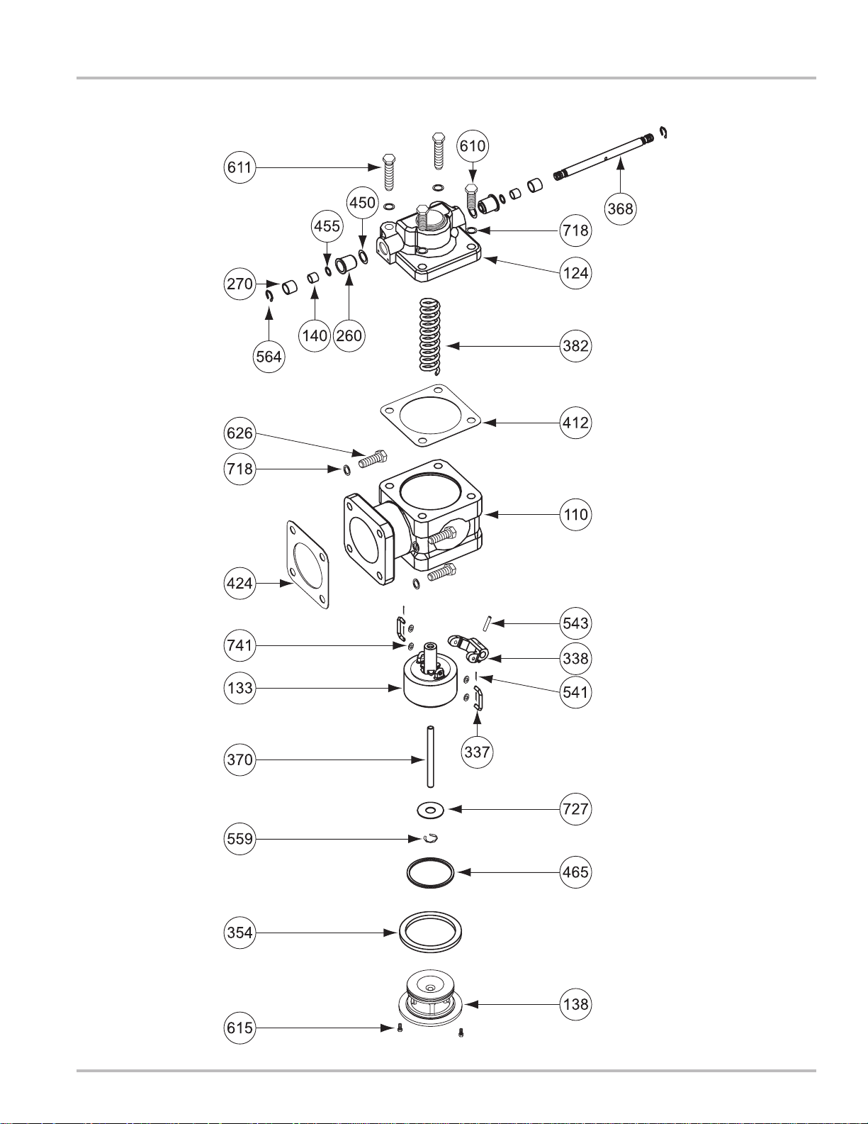
A-3610 Shown
Illustrated Parts Breakdown - V-15 Valves
17
Page 18

Illustrated Parts Breakdown - V-30 Valves
Item No. Description Part No.
11 0 Housing Sub-Assembly 40931
124 Valve Cap 43976
133 Cup 43528
138 Guide 43956
140 Bearing (2) 09050
260 Inner Bearing Guide (2) 47889
270 Shaft Case Seal (2) 47892
337 Link (2) 43525
338 Link Arm 43524
354 Seal Ring 46239
368 Valve Shaft 40987
370 Guide Shaft 40967
382 Compression Spring 40942
412 Flange Gasket (2) 40704
450 O-Ring (2) 09048
455 O-Ring (2) 09311
465 Upper Seal Ring 40969
541 Cotter Pin (4) 04005
543 Tapered Groove Pin 06822
559 Retaining Ring 04001
564 Retaining Ring (2) 04003
610 Screw, .625-11 x 1.75 (6) 04762
611 Screw, .625-11 x 2.50 (2) 06466
615 Screw, #10-24 x .375 (2) 06819
718 Flat Washer (8) 04764
727 Dashpot Washer 40944
741 Flat Washer (4) 06818
Model No. A4610 A4611 A4612 A4622AA4623 A4624
Item No.
110 40931 40931 40931 40931 40931 40931
124 43976 43976 43976 43976 43976 43976
133 43528 43734 43528 43528 43528 43528
138 43956 43956 43979 43979 43956 43956
140 09050 09050 09050 09050 09050 09050
260 47889 47889 47889 47889 47889 47889
270 47892 47892 47892 47892 47892 47892
337 43525 43525 43525 43525 43525 43525
338 43524 43524 43524 43524 43524 43524
354 46239 46239 43981 43981 46239 46239
368 40987 40987 40987 40987 40987 40987
370 40967 40967 40967 40967 40967 40967
382 40942 43526 40942 43526 43526 43526
412 40704 46072 40704 40704 46072 40704
450 09048 09048 09049 09049 09048 09048
455 09311 09311 09045 09045 09311 09311
465 40969 40969 07202 07202 40969 40969
541 04005 06936 04005 06936 06936 06936
543 06822 06822 06822 06822 06822 06822
559 04001 N/A 04001 06820 06820 06820
564 04003 06821 04003 06821 06821 06821
572 N/A N/A 07203 07203 N/A N/A
610 04762 04762 04762 04762 04762 04762
611 06466 06466 06466 06466 06466 06466
615 06819 06819 06819 06819 06819 06819
626 N/A N/A N/A N/A 04762 04762
718 04764 04764 04764 04764 04764 04764
727 40944 N/A 40944 43521 43521 43521
741 06818 06818 06818 06818 06818 06818
Part No.
*N/S = Not for Sale
18
Page 19

A-4610 Shown
Illustrated Parts Breakdown - V-30 Valves
19
Page 20

Illustrated Parts Breakdown - VS-3 Valves
Item No. Description Part No. Item No. Description Part No.
11 0 Housing Sub-Assembly N/S*
124 Cap Sub-Assembly 45533
133 Cup 43528
138 Machined Guide 45530
139 Retainer Ring Guide (2) 45521
140 Bearing (2) 09050
260 Inner Bearing Guide (2) 47890
270 Shaft Case Seal (2) 47893
337 Link (2) 43525
338 Link Arm 43524
354 Seal Ring 46239
368 Cap Shaft 45507
370 Guide Shaft 40967
382 Compression Spring 40942
420 Flange Gasket 07261
450 O-Ring 07504
451 O-Ring (2) 09048
Model No. A36501 A36502 A36521 A36522 A36551 A36552 A36572 A36582
Part No.
*N/S = Not for Sale
Item No.
110 N/S* N/S N/S N/S N/S N/S N/S N/S
124 45533 45533 45533 45533 45533 45533 45533 45533
133 43528 45528 43528 45528 43528 45528 45528 45528
138 45530 45529 N/S* 45526 45530 45529 45529 45526
139 45521 45521 45521 45521 45521 45521 45521 45521
140 09050 09050 09050 09050 09050 09050 09050 09050
260 47890 47890 47890 47890 47890 47890 47890 47890
270 47893 47893 47893 47893 47893 47893 47893 47893
337 43525 43525 43525 43525 43525 43525 43525 43525
338 43524 45531 43524 45531 43524 45531 45531 45531
354 46239 46239 43981 43981 46239 46239 46239 43981
368 45507 45507 45507 45507 45507 45507 45507 45507
370 40967 40967 40967 40967 40967 40967 40967 40967
382 40942 40942 40942 40942 40942 40942 40942 40942
390 N/A N/A N/A N/A N/A N/A N/A 07269
420 07261 07261 07261 07261 07262 07262 07261 07261
450 07504 07504 07608 07608 07504 07504 07504 07608
451 09048 09048 09049 09049 09048 09048 09048 09049
453 40969 40969 07202 07202 40969 40969 40969 07202
455 07611 07611 07612 07612 07611 07611 07611 07612
456 09311 09311 09045 09045 09311 09311 09311 09045
533 07212 07212 07212 07212 06985 06985 07212 07212
541 04005 04005 04005 04005 04005 04005 04005 04005
543 06822 06822 06822 06822 06822 06822 06822 06822
559 04001 04001 04001 04001 04001 04001 04001 04001
564 04003 04003 04003 04003 04003 04003 04003 04003
572 N/A N/A 07203 07203 N/A N/A N/A 07203
611 07255 07255 07255 07255 07255 07255 07255 07255
614 07293 07293 07293 07293 N/S N/S 07293 07293
627 07613 07613 07613 07613 07613 07613 07613 07613
650 45241 45241 45241 45241 45242 45242 45249 45249
718 07256 07256 07256 07256 07256 07256 07256 07256
727 40944 40944 40944 40944 40944 40944 40944 40944
741 04789 04789 04789 04789 04789 04789 04789 04789
745 06174 06174 06174 06174 06174 06174 06174 06174
453 Upper Seal Ring 40969
455 O-Ring 07611
456 O-Ring (2) 09311
533 Nut, .625-11 (4) 07212
541 Cotter Pin (4) 04005
543 Tapered Groove Pin 06822
559 Retaining Ring 04001
564 Retaining Ring (2) 04003
611 Screw, .750-10 x 2.25 (4) 07255
614 Screw, .625-11 x 2.75 (4) 07293
627 Screw, .250-20 x .625 (4) 07613
650 Stud, Nut, Gasket Kit 45241
718 Flat Washer (4) 07256
727 Dashpot Washer 40944
741 Flat Washer (4) 04789
745 Lock Washer (4) 06174
20
Page 21

A-36501 Shown
Illustrated Parts Breakdown - VS-3 Valves
21
Page 22

Illustrated Parts Breakdown - VS-4 Valves
Item No. Description Part No.
11 0 Housing Sub-Assembly N/S*
124 Cap Sub-Assembly 45533
133 Cup 43528
138 Machined Guide 45530
139 Retainer Ring Guide (2) 45521
140 Bearing (2) 09050
260 Inner Bearing Guide (2) 47890
270 Shaft Case Seal (2) 47893
337 Link (2) 43525
338 Link Arm 43524
354 Seal Ring 46239
368 Cap Shaft 45507
370 Shaft Guide 40967
382 Compression Spring 40942
420 Flange Gasket 07263
450 O-Ring 07504
451 O-Ring (2) 09048
453 Upper Seal Ring 40969
455 O-Ring 07611
456 O-Ring (2) 09311
533 Nut, .625-11 (8) 07212
541 Cotter Pin (4) 04005
543 Tapered Groove Pin 06822
559 Retaining Ring 04001
564 Retaining Ring (2) 04003
611 Screw, .750-10 x 2.25 (4) 07255
614 Screw, .625-11 x 2.75 (8) 07293
627 Screw, .250-20 x .625 (4) 07613
650 Stud, Nut, Gasket Kit 45248
718 Flat Washer (4) 07256
727 Dashpot Washer 40944
741 Flat Washer (4) 04789
745 Lock Washer (4) 06174
Model No. A46501 A46502 A46521 A46522 A46551 A46522
Item No.
110 N/S* N/S N/S N/S 45524 45524
124 45533 45533 45533 45533 45533 45533
133 43528 45528 43528 45528 43528 45528
138 45530 45529 45527 45526 45530 45529
139 45521 45521 45521 45521 45521 45521
140 09050 09050 09050 09050 09050 09050
260 47890 47890 47890 47890 47890 47890
270 47893 47893 47893 47893 47893 47893
337 43525 43525 43525 43525 43525 43525
338 43524 45531 43524 45531 43524 45531
354 46239 46239 43981 43981 46239 46239
368 45507 45507 45507 45507 45507 45507
370 40967 40967 40967 40967 40967 40967
382 40942 40942 40942 40942 40942 40942
420 07263 07263 07263 07263 N/S N/S
450 07504 07504 07608 07608 07504 07504
451 09048 09048 09049 09049 09048 09048
453 40969 40969 07202 07202 40969 40969
455 07611 07611 07612 07612 07611 07611
456 09311 09311 09045 09311 09311 09311
533 07212 07212 07212 07212 06985 06985
541 04005 04005 04005 04005 04005 04005
543 06822 06822 06822 06822 06822 06822
559 04001 04001 04001 04001 04001 04001
564 04003 04003 04003 04003 04003 04003
572 N/A N/A 07203 07203 N/A N/A
611 07255 07255 07255 07255 07255 07255
614 07293 07293 07293 07293 N/S N/S
627 07613 07613 07613 07613 07613 07613
650 45248 45248 45248 45248 45243 45243
718 07256 07256 07256 07256 07256 07256
727 40944 40944 40944 40944 40944 40944
741 04789 04789 04789 04789 04789 04789
745 06174 06174 06174 06174 06174 06174
Part No.
*N/S = Not for Sale
22
Page 23

A-46501 Shown
Illustrated Parts Breakdown - VS-4 Valves
23
Page 24

A Unit of IDEX Corporation
105 Albrecht Drive
Lake Bluff, IL 60044-2242
1.800.458.5262 • 847.295.1050
Fax: 847.295.1057
www.lcmeter.com
© 2007 Liquid Controls
Pub. No. 48854B
(02/07)
 Loading...