

Page 1
INSTALLATION & OPERATION
MANUAL
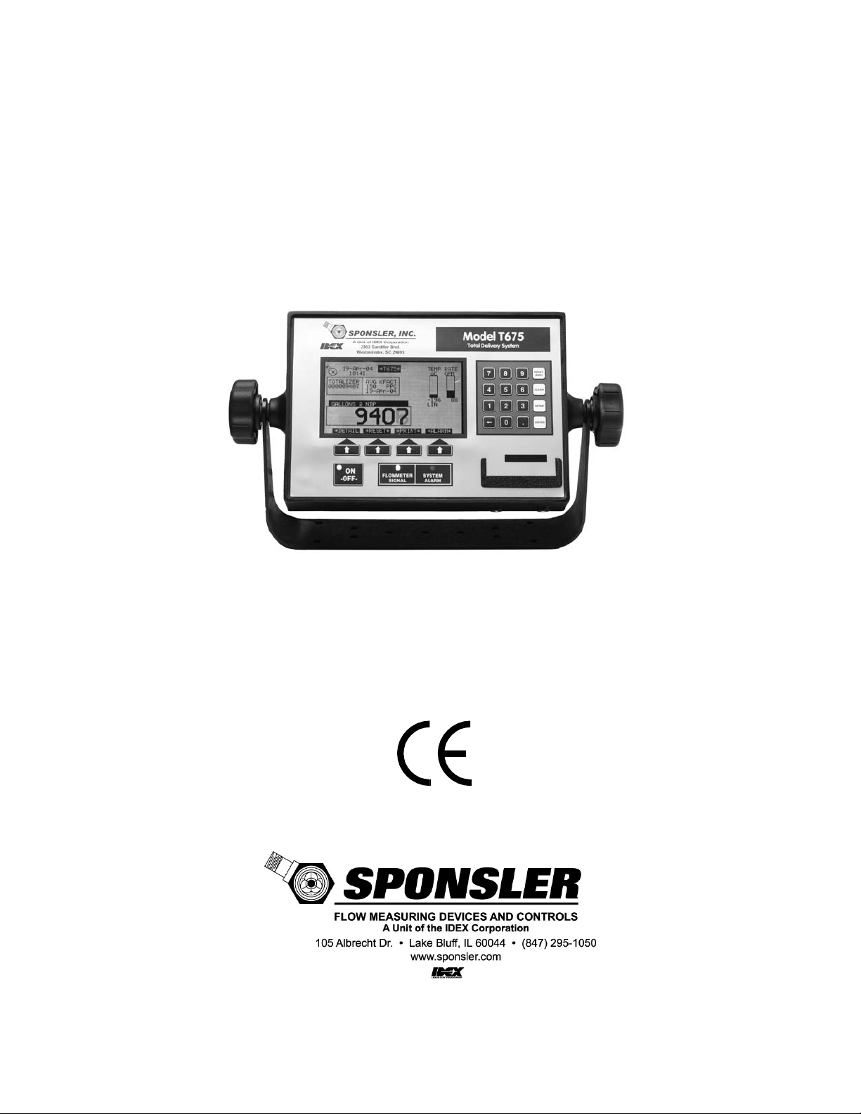
Model T675
Delivery System Totalizer
Page 2

Sponsler, Inc.
Model T675 Flow Totalizer
Table of Contents
Pg. ii
Table of Contents
1. GENERAL INFORMATION: ................................................................................................................................................................................... 1
1.1 INSTALLATION GUIDE ................................................................................................................................................................................. 1
1.1.1 Introduction: ......................................................................................................................................................................................... 1
1.1.2 Precautions: ......................................................................................................................................................................................... 1
1.1.3 Totalizer: .............................................................................................................................................................................................. 1
1.1.4 Interconnecting Cables: ....................................................................................................................................................................... 1
1.2 WARRANTY .................................................................................................................................................................................................... 1
2. FEATURES OVERVIEW: ........................................................................................................................................................................................ 2
2.1 INTRODUCTION ............................................................................................................................................................................................. 2
2.2 FEATURES ...................................................................................................................................................................................................... 2
2.3 SYSTEM OVERVIEW ..................................................................................................................................................................................... 3
2.4 THEORY OF OPERATION ............................................................................................................................................................................. 3
2.5 CONTROL PANEL INDICATORS ................................................................................................................................................................. 3
2.6 CONTROL PANEL PUSHBUTTONS ............................................................................................................................................................. 3
2.7 DISPLAY .......................................................................................................................................................................................................... 4
2.7.1 Power Up Display ................................................................................................................................................................................ 4
2.7.2 Operating Display ................................................................................................................................................................................ 4
2.7.3 Detail Display ....................................................................................................................................................................................... 5
2.7.4 Prover Display...................................................................................................................................................................................... 6
2.8 MODES OF OPERATION ............................................................................................................................................................................... 6
2.8.1 Operating Mode ................................................................................................................................................................................... 6
2.8.2 Programming Mode.............................................................................................................................................................................. 6
2.8.3 Prove Mode .......................................................................................................................................................................................... 6
3. PROGRAMMING: ....................................................................................................................................................................................................
3.1 – SET CLOCK : ................................................................................................................................................................................................. 7
3.1.1 – Set time .............................................................................................................................................................................................. 8
3.1.2 – DST star ............................................................................................................................................................................................. 9
3.1.3 – DST end ............................................................................................................................................................................................. 9
3.2 – ADJUSTMENT MODE: .............................................................................................................................................................................. 10
3.2.1 – Calibration ...................................................................................................................................................................................... 10
3.2.1.1 – Avg. Kfactor .............................................................................................................................................................. 10
3.2.1.2 – Linearizer ................................................................................................................................................................... 11
3.2.1.3 – Linearizer on/off ........................................................................................................................................................ 13
3.2.2 – Configuration .................................................................................................................................................................................. 13
3.2.2.1 – Compensation active .................................................................................................................................................. 13
3.2.2.2 – Trailer product ........................................................................................................................................................... 13
3.2.2.3 – Units of measure ........................................................................................................................................................ 14
3.2.2.4 – Digits right of decimal ............................................................................................................................................... 15
3.2.2.5 – Use dual coil .............................................................................................................................................................. 15
3.2.2.6 – Use printer checking .................................................................................................................................................. 15
3.3 – CHANGE SYSTEM SETTINGS: ................................................................................................................................................................ 16
3.3.1 675 Settings Menu Page 1 .................................................................................................................................................................. 16
3.3.1.1 – Flowmeter Size .......................................................................................................................................................... 17
3.3.1.2 – Alarm and Timer settings ......................................................................................................................................... 177
3.3.1.2.1 – Totalize during alarm ........................................................................................................................... 18
3.3.1.2.2 – Pump cooldown timer .......................................................................................................................... 18
3.3.1.2.3 – Pump cooldown delay.......................................................................................................................... 18
3.3.1.2.4 – Intermittent temp. tolerance ................................................................................................................. 18
3.3.1.2.5 – Pump on during alarm ......................................................................................................................... 19
3.3.1.2.6 – Count while temp fail .......................................................................................................................... 19
3.3.1.3 – Serial numbers ........................................................................................................................................................... 19
3.3.1.3.1 – Flowmeter ............................................................................................................................................ 19
3.3.1.3.2 – Plant ..................................................................................................................................................... 20
3.3.1.3.3 – Trailer .................................................................................................................................................. 20
3.3.1.3.4 – 675 S/N ................................................................................................................................................ 20
3.3.1.3.5 – 675 manufacture date ........................................................................................................................... 20
3.3.1.3.6 – BT authenticate #675 manufacture date ............................................................................................... 20
3.3.1.4 – User passcode ............................................................................................................................................................ 21
3.3.1.5 – Maintenance .............................................................................................................................................................. 21
7
Page 3

Sponsler, Inc.
Model T675 Flow Totalizer
Table of Contents
Pg. iii
3.3.1.5.1 – System maintenance due DDMMYY .................................................................................................. 21
3.3.1.5.2 – System maintenance just performed .................................................................................................... 21
3.3.1.5.3 – Turbine hrs until maintenance ............................................................................................................. 22
3.3.1.5.4 – Turbine maintenance just performed ................................................................................................... 22
3.3.1.5.5 – Pump hours until maintenance ............................................................................................................. 22
3.3.1.5.6 – Pump maintenance just performed ....................................................................................................... 22
3.3.1.6 – Printer Type ............................................................................................................................................................... 23
3.3.1.7 – System alarm log ....................................................................................................................................................... 23
3.3.1.8 – System activity ........................................................................................................................................................... 24
3.3.1.0 – Go to page 2............................................................................................................................................................... 24
3.3.2 675 Settings Menu Page 2 .................................................................................................................................................................. 25
3.3.2.1 – View Audit Trail ........................................................................................................................................................ 25
3.3.2.1.1 – Calibration event log ........................................................................................................................... 26
3.3.2.1.2 – Configuration event log ....................................................................................................................... 26
3.3.2.1.3 – Event counters ..................................................................................................................................... 27
3.3.2.1.4 – Print audit trail logs ............................................................................................................................. 28
3.3.2.2 – Printer format 1/2 ...................................................................................................................................................... 29
3.3.2.2.1 – Product ................................................................................................................................................ 29
3.3.2.3 – Printer format 2/2 ...................................................................................................................................................... 30
3.3.2.3.1 – Delivery Unit of Measure .................................................................................................................... 30
3.3.2.4 – Printer Comm ............................................................................................................................................................ 30
3.3.2.4.1 – Baud rate .............................................................................................................................................. 31
3.3.2.4.2 – EOL character ...................................................................................................................................... 31
3.3.2.4.3 – Use Bluetooth ...................................................................................................................................... 31
3.3.2.5 – Print timeout .............................................................................................................................................................. 31
3.3.2.5a – Sample Delivery Ticket ............................................................................................................................................ 32
3.3.2.6 & 7, – Spare .................................................................................................................................................................. 33
3.3.2.8 – Activation .................................................................................................................................................................. 33
3.3.2.9 – Loaner ........................................................................................................................................................................ 33
3.3.2.0 – Return to page 1......................................................................................................................................................... 33
3.4 – UPDATE SOFTWARE ................................................................................................................................................................................ 33
3.5 – HARDWARE TEST/CALIBRATE ............................................................................................................................................................. 33
3.6 – RESTART SYSTEM ................................................................................................................................................................................... 33
3.7 – SERIAL ECHO/DEBUG ............................................................................................................................................................................. 33
3.8 – LOANER ..................................................................................................................................................................................................... 34
3.9 – LCD SETUP ................................................................................................................................................................................................ 34
4. FIELD OPERATION ............................................................................................................................................................................................... 35
4.1 INITIAL POWER ON: ................................................................................................................................................................................... 35
4.2 COOLDOWN PROCEDURE: ........................................................................................................................................................................ 35
4.3 RESETTING THE TOTALIZER: ................................................................................................................................................................... 35
4.4 DELIVERY VARIABLES: ............................................................................................................................................................................ 36
4.5 FIELD CALIBRATION: ................................................................................................................................................................................ 37
4.5.1 Methods .............................................................................................................................................................................................. 37
4.5.2 Calculating a new Kfactor.................................................................................................................................................................. 37
4.5.3 Installing a new Kfactor ..................................................................................................................................................................... 37
5. TECHNICAL INFORMATION.............................................................................................................................................................................. 38
5.1 SPECIFICATIONS: ........................................................................................................................................................................................ 38
5.1.1 HARDWARE: ..................................................................................................................................................................................... 38
5.1.2 SOFTWARE: ...................................................................................................................................................................................... 39
5.2 SPARE PARTS: .............................................................................................................................................................................................. 39
5.3 SAMPLE FACTORY CALIBRATION SHEET ............................................................................................................................................. 40
5.4 SYSTEM DIAGRAMS ................................................................................................................................................................................... 41
5.4.1 Front, Rear, Side View and Mounting Bracket Dimensions: .............................................................................................................. 41
5.4.2 Rear Panel Connector Pin Assignments: ........................................................................................................................................... 42
5.4.3 Delivery Components Interconnect Wiring: ....................................................................................................................................... 43
5.4.4 Sealing Locations: .............................................................................................................................................................................. 44
5.4.5 Programming Quick Reference: ......................................................................................................................................................... 45
6. DECLARATION OF CONFORMITY ................................................................................................................................................................... 48
Page 4

Sponsler, Inc.
Model T675 Flow Totalizer
General Information
Pg. 1
1. GENERAL INFORMATION:
1.1 INSTALLATION GUIDE
1.1.1 Introduction:
The installation guidelines are specific to the T675 Totalizer. Please refer to the individual technical data sheets for
information pertaining to the turbine flowmeter, RTD temperature probe, and printer. Compliance with the following basic
guidelines permits the user to acquire maximum benefit of this asset.
1.1.2 Precautions:
The T675 incorporates sophisticated electronic components and many safeguards have been designed to minimize
susceptibility to static discharge and stray voltages. Every precaution for safe handling should still be observed. The most
common is to eliminate static or stray voltage by grounding oneself touching a conductive discharge surface.
Welding in the proximity of the T675 is not advised. Disconnect ALL cables at the T675 prior to welding activity.
The display lens is a plastic composite and should be cleaned with a soft fabric cloth. Paper towel products or dirty leather
gloves will score the lens and obscure visibility.
1.1.3 Totalizer:
The T675 should be mounted at a convenient viewing height and angle that minimizes the reduced visibility caused by
direct sunlight. Accessibility is also a prime consideration. A thin application of an Oxygen compatible lubricant on the
threaded bolts of the securing knobs eliminates any corrosion opportunity. The threaded brass receptacle prevents galling.
Although the T675 has been designed to withstand the rigors of the cryogenic transport environment, placement under
piping that defrosts or in the proximity of pumps that spray liquid is not recommended.
1.1.4 Interconnecting Cables:
All cables should be secured in place with proper stress relief and avoiding contact with the piping. Sufficient slack should
be maintained in the cables to permit the T675 Totalizer to be rotated forward for easy access to the rear panel
connections. Additionally, a thin application of a non-conductive Oxygen compatible lubricant to the male threads of the
nickel-plated connectors will provide an additional moisture barrier. To minimize interference of other operating systems or
low voltage events the power cable should be terminated at the battery or the most direct input source. The power input is
polarity insensitive. S.I. strongly recommends that power for the T675 be direct to the source.
1.2 WARRANTY
Sponsler Inc. hereafter referred to as S.I., products are warranted to be free from defects in material and workmanship
under normal use and intended service for a period of 1 year from the date of shipment. Any product returned prepaid to
S.I. within the warranty period and found by S.I. to be defective in workmanship or material, will be repaired or replaced
free of charge at the sole discretion of S.I.. Return shipment will be prepaid using the lowest cost means of transportation.
The warranty excludes but is not limited to products which are subjected to abuse, improper installation, altered, repaired
anywhere except S.I., repaired using parts other than issued by S.I., accident or used in service other than intended or
purchased.
In the event of defective product, contact Sponsler Inc. (800)258-1165 to receive a Return Material Authorization (RMA)
number. The RMA number should be prominently displayed on the return package. Return shipments without an RMA
number are not accepted by the Shipping and Receiving department.
Page 5

Sponsler, Inc.
Model T675 Flow Totalizer
Features Overview
Pg. 2
2. FEATURES OVERVIEW:
2.1 INTRODUCTION
The Model T675 Delivery System is a thoroughly engineered electronic totalizing system that incorporates the latest
technology and provides the most comprehensive features available to the industry. The T675 is designed to accurately
compute and display in real time, pertinent flow parameters in both digital and graphic form. The displayed total of the
product being delivered is continually corrected for the temperature of the product. Additional accuracy can be acquired by
linearizing the turbine flowmeter input signal. The T675 math processor permits direct reading of product totals in any
desired engineering unit in both US Customary and SI i.e., gallons, liters, pounds, kilograms, scf, m3 etc.
This next generation system delivers the most sought after system enhancements while maintaining a user-friendly
simplicity of operation. The Model T675 configuration settings can be reprogrammed in the field with relative ease.
Programming the T675 is simply a matter of selecting the desired operating criteria from an all-inclusive menu thus
eliminating the need to scroll through an entire flow chart to enter or change select data. Display of various flow properties
such as temperature and flow limits, fluid density, and equivalent volume is achieved automatically with the selection of
product to be measured and turbine size.
Fault detection and identification has never been easier. In addition to standard alarm icons the T675 provides a “Detail
Display” that lists operating conditions such as supply voltage, internal battery voltage, signal input frequency, coil and
RTD resistance, product and fluid temperature to name a few. Additionally, a System Alarm Log catalogs 16 events.
The T675 Maintenance program with ICON reminders can be customized to account for the varying operating conditions
that exist between installations. This feature allows the end user to extract maximum real world service intervals without
sacrificing effective maintenance.
2.2 FEATURES
• Easy to program, operate and understand
• 3x5 backlit full graphics display
• Dual microprocessors for real-time graphics, display of totals, temperature, pressure, flowrate and alarms
• Passcode protected configuration and calibration parameters
• Temperature Compensator supports 8 individual products, LOX, LIN, LAR, CO2, CCO2, LPG, LN2O, MAPP
• Delivery total can be toggled between metered and base conditions
• 'softkeys' simplify display operation
• Selectable 2 – 10 point flowmeter linearization
• Automatic delivery system maintenance reminders based on a date and/or turbine hours of operation
• Level 3 Audit trail for all sealable meteorological parameters
• The most current Kfactor change is displayed on the operating screen with date stamp
• System alarm log simplifies fault identification
• Totalizer will withstand complete loss of power for 2 seconds, then save all operating data
• Restores to previous operating mode after power restoration
• Programmable Pump Control features protect the delivery system and increases service life
• Bluetooth, Infrared and RS-232 communication ports
• IR interface with Models SP824, SP834 Portable Printers
• Easily compatible with other printers
Page 6

Sponsler, Inc.
Model T675 Flow Totalizer
Features Overview
Pg. 3
2.3 SYSTEM OVERVIEW
When introduced to flow the turbine flowmeter generates an AC sinewave signal within the pickup coil located directly
above the turbine’s rotor. The signal of the pickup coil is amplified, divided, corrected, and displayed by the T675. The
displayed total is corrected for temperature by sensing the resistance of the RTD temperature probe. Delivery information,
consisting of 17 selectable parameters, is transmitted via Bluetooth, the Infrared (I.R.), or RS232 communications port
depending on which data collection device or printer is selected. This unique integrated system provides the end user a
configurable, compact total delivery system.
2.4 THEORY OF OPERATION
The S.I. turbine flowmeter is a volumetric measurement device that measures fluid velocity with one moving component,
the rotor. The momentum of the flowing fluid engages the low mass rotor resulting in the rotor rotating at an angular
velocity that is proportional to the fluid velocity. The rotor’s rotation generates an AC sinewave signal in the pickup coil. S.I.
turbine flowmeters are linear devices therefore the signal output frequency is proportional to the flowrate within the
designed flow range. Another benefit of a linear turbine meter is its Kfactor, the number of pulses generated per unit
volume (gallons, pounds etc.) is consistent over the entire flow range. The total number of pulses generated is directly
related to the total volume. The displayed total in the desired engineering unit is acquired by dividing the total pulses by the
Kfactor. Because volumetric flowmeters and product density are influenced by fluid temperature, temperature must be
measured and calculated into the final summation for the displayed total to be exact. A temperature compensation
algorithm accomplishes this by computing the fluid density for the measured temperature and adjusts the volumetric or
mass delivery total.
Simply stated, temperature compensation adds pulses to the pulse total when the detected temperature is colder than the
products reference temperature and subtracts pulses when the product temperature is warmer than the reference
temperature. The rate at which the pulses are added or subtracted is determined by the measured temperature departure
from the products reference temperature.
2.5 CONTROL PANEL INDICATORS
POWER INDICATOR: A Green LED illuminates when the T675 is “On” and is extinguished when the T675 is “Off”.
SIGNAL INDICA TOR: An Amber LED flashes when an input signal is present.
SYSTEM ALARM INDICATOR: A Red LED flashes indicating the presence of an Alarm or Maintenance condition.
BLUETOOTH INDICATOR: A purple LED flashes when searching for a connection and is on steady when connected.
2.6 CONTROL PANEL PUSHBUTTONS
ON/OFF PUSHBUTTON: Momentarily depressing the On/Off pushbutton will turn the T675 system “On” illuminating the
green LED. The system resumes operation exactly as existed at the moment of the last power “Off”. In order to turn the
T675 “Off” during normal operation you must depress and hold
turn “Off”. During the brief delay the Green Power LED will flash as a warning indicator. Once the display backlight
extinguishes the On/Off pushbutton can be released.
As a safeguard, during some critical operations such as system setup, the On/Off pushbutton is disabled. This allows the
operator to complete the setup operation (or exit setup first via the Reset/Esc key). Either way changes will be saved
before the system powers “Off”.
KEYPAD: A 16 pushbutton keypad, 10 numeric, decimal point, backspace key () and 4 special function keys, used for
data entry during setup of the T675. During normal operation (Operating mode) the keypad is disabled with the exception
of the Setup key.
SETUP: Changes the T675 from the Operating to the Prove mode.
RESET (ESC): Enables escape function, will initiate system reset only in Programming mode when “double
clicked”
the On/Off pushbutton for 3 seconds before the system will
Page 7

Sponsler, Inc.
Model T675 Flow Totalizer
Features Overview
Pg. 4
CLEAR: permits deletion of an entire user entry.
ENTER: inputs data only in Programming mode
SOFTKEYS: 4 keys located immediately below the display whose function is defined by an on Display label directly above
the key. During normal operation the Detail, Reset, Print, and Alarm softkeys are depicted on Display.
DETAIL SOFTKEY: Depressing this softkey will display the Detail Display. Once the Detail Display is displayed
the softkey now converts to a Hold softkey and retains the Detail Display until this softkey is released. Releasing
the Hold softkey permits the display to return to the Operating Display.
Two additional softkeys are displayed while in the Detail Display, Bat Test, and Ok softkey.
RESET SOFTKEY: Depressing this softkey resets the Delivery Totalizer. This softkey is disabled during delivery
unless the unit is in the Prove Mode.
PRINT SOFTKEY: Depressing this softkey downloads delivery data selected in T675 Settings Menu page 2
Items 2,3 for a period of time as programmed in T675 Settings Menu page 2 Item 5 . This key will not be
displayed if the printer output has been disabled in the T675 Settings Menu page 1 Item 6.
ALARM SOFTKEY: Depressing this softkey displays a description of all current alarm conditions. Once the Alarm
Display is displayed this softkey converts to an Ok softkey. A Hold and Next softkey also appear. Hold retains the
display until released plus 5 seconds, Ok returns to the Operating screen immediately, otherwise the Alarm
Display is retained for 5 seconds. Depressing Next will display all delivery
alarms that occurred.
2.7 DISPLAY
The T675 has 4 primary Displays; Power Up, Operating, Detail, and Prove. In addition there are 3 primary menu
Displays, the Initialization Menu, Adjustment Menu and the Settings Menu.
2.7.1 Power Up Display
When the T675 measurement system is initially turned “On”, this displays the self-test results, software version
identification and temperature correction curves. Additionally, a configurable message can be programmed and displayed
on the lower portion of the Display. The message is factory configurable and must fit within an area of 48 x 240 pixels.
For more detailed information about “power on self-test” consult the SYSTEM DIAGNOSTICS section of this manual.
2.7.2 Operating Display
CUSTOMER'S ICON: The icon is located in the upper left corner of the display and can be customized for the end user.
The icon must be digitized to fit within 24 x 24 pixels.
TIME & DATE: The current time and date as set by the system's real time clock (24-hr format). The colon separating the
hours and minutes will flash once per second to indicate that the system is functioning. Note that the clock is automatically
corrected for the transition between Daylight savings time and Standard time.
TEMPERATURE BARGRAPH: The temperature bargraph indicates the process temperature of the product being
delivered in relation to the minimum and maximum temperature limits automatically determined by the product correction
table loaded into the system when the product is selected. The product and digital temperature are displayed directly
beneath the bargraph. Temperature unit as selected in the Setup menu is displayed above the bargraph. The temperature
bargraph is updated every second. Note: if the delivery temperature is out of range, the 'Temp' descriptor above the
bargraph and red System Alarm LED will flash.
FLOWRATE BARGRAPH: The flowrate bargraph indicates the current flowrate of the product being delivered in relation to
the minimum and maximum flowrate limits automatically determined when the turbine flowmeter size is selected in the
Setup menu. The flowrate is digitally displayed directly beneath the bargraph in engineering units selected in the Setup
menu. The engineering unit of the rate is displayed above the rate bargraph. The flowrate is calculated with the Kfactor
entered in the Setup menu. The flowrate bargraph is updated every second. Note: if the delivery flowrate is out of range,
the 'Rate' descriptor and red System Alarm LED will flash (only when the “Use dual coil” option is set to “Off”).
Page 8

Sponsler, Inc.
Model T675 Flow Totalizer
Features Overview
Pg. 5
ACCUMULATIVE TOTALIZER: The 'small' 9 digit totalizer. This totalizer is “slaved” to the Delivery Totalizer and
increments in the same engineering units. The total is “Privilege” passcode protected and can only be Reset by factory
personnel. If the engineering unit of the total is changed, the displayed accumulated total will be converted automatically to
the equivalent total in the new engineering unit.
KFACTOR INFORMATION: The displayed Kfactor information has a dual purpose. If the linearizer is inactive, the
displayed Kfactor represents the latest Kfactor entered into the setup menu. If the linearizer is active, the Kfactor
information is replaced with the word linearizer. The instantaneous calculated linearized Kfactor based on flow rate is
available on the Detail Display.
DELIVERY TOTAL: The 6-digit delivery total represents the cumulated total since the last Reset action. (Refer to RESET
softkey pg. 4) The delivery total is the total pulses generated divided by the Kfactor and corrected for temperature if
compensation is activated. If the engineering unit of measure is changed the displayed delivery total will be automatically
reset to zero.
Directly above the Delivery Totalizer the engineering units of measure and delivery conditions are displayed. If the
temperature compensator is activated and the delivery temperature is within range, the engineering unit of measure will be
displayed with 'corrected @ NBP'. The total will be corrected to metered conditions, (at the measured temperature). If the
delivery temperature is out of range, '@ DEFAULT TEMP' will be displayed and the delivery total will be corrected at the
warmest delivery temperature for that product. Depressing the key will change the displayed total to the uncorrected
quantity and '–uncompensated' will be displayed above the total. If the temperature compensator function is turned “Off”,
'@ NO TCF' will be displayed and the TCF will be 1.000, (volumetric).
The delivery totalizer will continue counting in the event of a temperature failure if “Count while temp fail” option is
selected in the Setup menu. If “Totalize during alarm” is selected the totalizer will operate at the warmest temperature
value (default temp) for the selected product while the temperature is out of range.
PUMP ICON: The pump icon indicates the status of the delivery pump. When the pump icon is not displayed, the delivery
pump is enabled. A temperature and time based pump cooldown feature can be activated by enabling the Pump
Cooldown Timer. In the event of an intermittent non-fatal temperature error, the Intermittent Temp Tolerance Timer is
activated. This programmable timer specifies a time period during which a temperature fault is allowed to exist without
disabling the delivery pump. During this failure a thermometer icon with an upward pointing arrow and countdown timer will
appear on the Operating Display indicating the number of seconds remaining before the temperature fault will disable the
delivery pump unless corrected. Failure to correct the temperature fault within the specified time will cause the pump icon
to be displayed, disable the delivery pump, and reset the Pump Cooldown Delay Timer to the programmed value. When
the fault is corrected and the temperature returns within range, the pump cooldown delay timer will decrement toward zero.
If no further temperature errors occur, the pump cooldown delay timer will reach zero, the pump icon will disappear, and
the delivery pump will be enabled.
SYSTEM MAINTENANCE ICON: An oil can icon indicates that a system maintenance alarm condition exists. An
abbreviated alarm message is displayed below the icon identifying the component. If more than one alarm condition exists,
the alarm message(s) will be displayed in a sequential fashion. Depressing the ALARM softkey will display all current
alarm conditions. The System Alarm Log in the “675 settings menu” maintains an alarm event history that can be
accessed by Privileged or User passcodes. The System Alarm LED indicator flashes during any alarm condition. In the
event a low power condition is detected, the alarm icon converts to a gas pump and begins a 2 second countdown. During
this low power condition, the system turns off the LCD backlight to conserve power and begins operating off the internal
lithium battery. If the incoming power is restored within 2 seconds, the system will refresh and operate normally. If,
however, sufficient power is not restored, the system will save all operating parameters and shut itself “Off”.
*T675* MESSAGE: This message indicates that the unit is in the normal Operating mode. When this message is
replaced with ‘PROVER’ the unit is operating in the Prove mode.
2.7.3 Detail Display
The Detail Display shows hardware information and additional current operating conditions of the system. A total of 14
parameters are available for review; Adjustment Mode access status, dual coil status, Input voltage, Battery voltage, P/U
coil ohms, LCD Heater status, Input frequency, Kfactor, RTD ohms, Communications Baud rate, Printer Status, T/C factor,
Density, Delivery product and Temperature. The temperature is displayed in digital and bargraph format.
Page 9

Sponsler, Inc.
Model T675 Flow Totalizer
Features Overview
Pg. 6
3 Softkeys displayed with the Detail Display:
BAT TEST SOFTKEY: Depressing this key while in the Detail Display instructs the system to test the T675
backup battery. This test involves applying a 35mA load to the battery for 2 seconds, reading and storing the
battery voltage. Since this test evaluates the battery’s condition by applying a load, it is recommended that this test
be conducted only if either Batt is below the Maintenance icon or a new battery is installed. The system
automatically performs this test at the beginning of each month.
OK SOFTKEY: Depressing this key terminates the Detail Display and immediately returns the display to the
Operating Display.
HOLD SOFTKEY: Depressing this key retains the Display, when released the system will automatically revert to
the Operating Display after several seconds.
2.7.4 Prover Display
Depressing the Setup key located on the keypad accesses the Prover Display. This Display is identical to the
Operational Display with the exception of the *T675* icon is replaced with the word PROVER. The function of the Prove
mode is examined in detail below. Note: When the Program Enable Module (PEM) is secured to the T675, the Setup key
is disabled and access to the Prove mode is denied.
2.8 MODES OF OPERATION
The T675 program offers 3 modes, Operating, Programming, and Prove. Any mode that can affect the calibration of the
T675 is passcode protected. The T675 has a 2 tiered passcode level of security, Privileged and Weights and Measures.
The Privileged passcode is maintained exclusively for Factory use and allows access to ALL menu options. The Weights
and Measures passcode allows access to all displayed menu options except Initialization Options 5,8, and 9.
2.8.1 Operating Mode
The Operating mode is the power up mode for the T675, all others must be accessed with a passcode. The Operating
Display containing all delivery vitals is the normal display for this mode. The Detail Display is also accessible in this mode
without a passcode.
2.8.2 Programming Mode
The Programming mode and associated menu’s allow the T675 to be configured to the operating conditions of the
application. When accessed, the first Display is 675 Initialization Options menu containing 8 options. Options 2, 3, 5 and
8 are passcode protected. Options 5, 8, and 9 require a Privileged passcode and are intended for Factory use only. The
Programming mode is quite extensive and is explained completely beginning with the 675 Initialization Opti o n s Menu
on page 7.
2.8.3 Prove Mode
The Prove mode permits convenient calibration of the trailer’s delivery system. This mode temporarily aborts certain
safeguard features and therefore is passcode protected. To access this mode, depress the SETUP key while in Operating
mode. The system will prompt for a passcode, either user or privileged, to be entered. If an incorrect passcode is entered
or the RESET/(ESC) key is depressed, the T675 will revert to the Operating mode. The Prove mode allows entering,
changing or viewing the Kfactor. The Prove mode is retained until the T675 is either turned “Off” or no flow activity for 5
minutes. The Prove mode has the following operational characteristics:
• The *T675* message is replaced with the PROVER message
• The SETTINGS passcode is not required to change the Kfactor
• The pump cooldown timer is disabled (pump enabled)
• The I.R. communications port is disabled
• The Totalizer can be reset regardless of flowrate
• “Not a legal delivery” is displayed above the delivery totalizer and on a printed ticket
Page 10

Sponsler, Inc.
Model T675 Flow Totalizer
Technical Information
Pg. 7
****** 675 Initialization options ******
1 - Set clock
#%
2 – Adjustment Mode
# 3 - Change system settings
% 4 – Update software
5 - Hardware test/calibrate
6 - Restart system
7 – Serial Echo/Debug
*
8 – Loaner
9 – LCD setup
Option?
****** Setting clock ******
2 – DST start
3 – DST end
Option?
3. PROGRAMMING:
The T675 Initialization Options Menu is accessed when the unit is off by depressing and holding the RESET key while
momentarily depressing and releasing the On/Off pushbutton. Options 1,2, and 3 in this menu contain the entire program
configuration Displays to customize the T675. Simply select the corresponding number. If the Programming Enable
Module is attached Option 2 - Adjustment Mode will display Disabled.
Example: Access Change system settings <3> <Passcode> <ENTER>
*%
# Passcode required (items 2 & 3)
% T675-PEM must not be installed (items 2,4 & 5)
* Privileged passcode is required (items 5 & 8)
NOTE: 1) Items 2,4 & 5 show “disabled” if the PEM is installed
2) Entry of the Passcode is not displayed, a * is displayed with each digit maintaining confidentiality.
3) Depressing the RESET key during data entry will return the display to the previous menu Display
without changing the data.
4) Any item within the < > borders signifies depressing that key or pushbutton.
5) key backspaces an entry 1 position each time it is depressed
6) CLEAR key deletes entire entry
3.1 – SET CLOCK:
Sets the T675's real time clock and Daylight Saving Time (DST) start and end dates. Depressing the RESET softkey
anytime during the entry sequence aborts programming and returns to the Setting clock display. Depressing the RESET
softkey a second time returns to the 675 Initialization Options display.
1 – Set time
Page 11

Sponsler, Inc.
Model T675 Flow Totalizer
Technical Information
Pg. 8
****** Setting real time clock ******
Current setting: 11:54 01-Oct-07
Hours (0-23) ?
****** Setting real time clock ******
Current setting: 11:54 01-Oct-07
Minutes (0-59)?
****** Setting real time clock ******
Current setting: 11:54 01-Oct-07
Date (1-31) ?
****** Setting real time clock ******
Current setting: 11:54 01-Oct-07
Month (1-12) ?
****** Setting real time clock ******
Current setting: 11:54 01-Oct-07
Year (0-99) ?
3.1.1 – Set time
The clock is a military time format. In this function the Display will automatically advance to the next setting with
each entry.
To program Set time: <1>
Example: Set 1:35pm October 1, 2007;
<13> <ENTER>
<35> <ENTER>
<1> <ENTER>
<10> <ENTER>
<7> <ENTER>
To confirm that the Current setting is correct <1> Set clock and review. <RESET> to exit and return to the
675 Initialization options menu.
Page 12

Sponsler, Inc.
Model T675 Flow Totalizer
Technical Information
Pg. 9
****** DST start (0=NONE) ******
Current: week=0 Month=00
Sunday of mth (0-5)?
****** DST start (0=NONE) ******
Current: week=0 Month=00
Month (1-12)?
****** DST end (0=NONE) ******
Current: week=0 Month=00
Sunday of mth (0-5)?
****** DST end (0=NONE) ******
Current: week=0 Month=00
Month (1-12)?
3.1.2 – DST start
When DST starts is determined by selecting which Sunday of the month DST is scheduled to begin. DST entries
must be completed by depressing the ENTER key. To program DST start: <2>
Example: Set DST to start March 2, 2008
<1> <ENTER>
<3> <ENTER>
3.1.3 – DST end
When DST ends is determined by selecting which Sunday of the month DST is scheduled to end. DST entries
must be completed by depressing the ENTER key. To program DST end: <3>.
Example: Set DST to end November 30, 2008
<5> <ENTER>
<11> <ENTER>
Page 13

Sponsler, Inc.
Model T675 Flow Totalizer
Technical Information
Pg. 10
************ Adjustment mode ***********
1 – Calibration
2 - Configuration
Enter setting (ESC to exit)?
***** Adjustment mode - Calibration ****
1 – Avg. Kfactor
2 – Linearizer table
3 – Linearizer (0=OFF, 1=ON)
Enter setting (ESC to exit)?
************* Avg. Kfactor *************
Current setting = 148.914
Enter setting (ESC to exit)?
3.2 – ADJUSTMENT MODE:
Permits the programming of sealable Calibration and Configuration parameters. Selecting this option will cause a prompt
for a passcode. Once the passcode is entered properly access is permitted. Refer to page 9 for complete Adjustment
programming instructions. If a T675-PEM (Programming enable module) is installed, the Adjustment Mode can only be
accessed by first removing the safety wire secured T675-PEM located on the bottom right of the T675 enclosure.
The Adjustment Mode contains the programmable Calibration and Configuration parameters. These sealable
parameters are passcode protected because they alter the calibration and/or billing accuracy. Depress the
corresponding category number in the left column, entry is automatic.
3.2.1 – Calibration
Allows setting the following parameters. Depress the corresponding category number in the left column, entry is
automatic.
3.2.1.1 – Avg. Kfactor
Allows entry of the average Kfactor in pulses per gallon. This Kfactor is used for all calculations when the linearizer
function is turned “Off”.
Example: Insert Kfactor = 148.914; <148.914> <ENTER>
Page 14

Sponsler, Inc.
Model T675 Flow Totalizer
Technical Information
Pg. 11
Initial Linearizer Display
Linearizer OFF meter: 0000
FREQ K-FACTOR
0- 10 100
1- 100 100
2- 1000 100
3- 0 0
4- 0 0
5- 0 0
6- 0 0
7- 0 0
8- 0 0
9- 0 0
Enter setting (ESC to exit)?
(SETUP toggles linearizer ON/OFF)
3.2.1.2 – Linearizer
Allows the T675 to take advantage of point to point programming using the turbine flowmeter calibration sheet to
enter frequency and corresponding Kfactor. The table is constructed from top to bottom
be entered in numerical order, Point 0 being the lowest frequency and Point 9 the highest. To abbreviate the
number of linearizer points enter 0 for the frequency after the last desired point. Once a frequency of zero has
been entered the table is considered complete and all points below are calculated at the last valid Kfactor.
Remember that the number of linearizer points can range from 2 – 10. As a convenience, <SETUP> key will
alternate the linearizer between activated or deactivated during this function. The Initial Linearizer Display
illustration is an example of a 3 point linearizer.
. The frequency data must
The linearizer option is versatile and allows customized programming that reflects the application. This process
can be simplified by reviewing the turbine flowmeter calibration sheet in advance and determine the following:
1) The extent of flow range coverage desired; 2) The number of points to linearize; 3)Where to distribute the
points, such as 3 points over the entire range, 5 points confined to the lower half of the flow range etc.
Page 15

Sponsler, Inc.
Model T675 Flow Totalizer
Technical Information
Pg. 12
Completed Linearizer Display
Linearizer OFF meter: 0000
FREQ K-FACTOR
0- 37.746 148.85
1- 96.122 148.44
2- 152.563 149.23
3- 212.368 148.48
4- 268.338 148.73
5- 328.613 148.74
6- 386.612 149.28
7- 445.852 149.41
8- 502.946 149.18
9- 563.061 148.80
0-freq? 37.746
Linearizer Point 0 Frequency Setup Display
Linearizer OFF meter: 0000
FREQ K-FACTOR
0- 10 100
1- 100 100
2- 1000 100
3- 0 0
4- 0 0
5- 0 0
6- 0 0
7- 0 0
8- 0 0
9- 0 0
0-freq? 37.746
Linearizer Point 0 KFactor Setup Display
Linearizer OFF meter: 0000
FREQ K-FACTOR
0- 10 100
1- 100 100
2- 1000 100
3- 0 0
4- 0 0
5- 0 0
6- 0 0
7- 0 0
8- 0 0
9- 0 0
0-Kfact? 148.85
Example: Using the 2” calibration
sheet (page 34), program the
linearizer for 10 points evenly
distributed over the entire flow range
(15 – 225gpm). Beginning with Point
0 - <0>, enter the lowest frequency
<37.746><ENTER>. The Display
advances to the Kfactor request;
enter the corresponding Kfactor
<148.85><ENTER>. Repeat this
process for points 1 – 9. When the
table is complete depress
RESET/(ESC) once to exit the
linearizer setup menu, twice to return
to the Kfactor setup menu and three
times to exit to the Operating mode.
After selecting a linearizer point
depressing ENTER will skip over the
entry prompt without changing the
existing value.
Once all the data has been entered
the Setup key can be used to toggle
the linearizer On and Off. The
linearizer status is displayed in the
upper left portion of the Display. In
the Operating mode the word
Linearize is displayed in place of the
actual Kfactor.
Page 16

Sponsler, Inc.
Model T675 Flow Totalizer
Technical Information
Pg. 13
******* Linearizer (0=OFF, 1=ON) *******
Current setting = 1
Enter setting (ESC to exit)?
**** Adjustment mode – Configuration ***
1 – Compensation (0=OFF, 1=ON)
2 – Product
3 – Units of Measure
4 – Digits right of decimal
5 – Use dual coil (0=NO, 1=YES)
6 – Printer checking (0=NO, 1=YES)
Enter setting (ESC to exit)?
****** Compensation (0=OFF, 1=ON) ******
Current setting = 1
Enter setting (ESC to exit)?
**************** Product ***************
Current setting = 2
1 – LOX
2 – LIN
3 – LAR
4 – LCO2
5 – LN20
6 – CC02
7 – MAPP
8 - LPG
3.2.1.3 – Linearizer on/off Activates or deactivates the linearizer function. <0> = Off, <1> = On
Example: To activate the linearizer; <1>
3.2.2 – Configuration
Allows setting the following parameters. Depress the corresponding category number in the left column, entry is
automatic.
3.2.2.1 – Compensation active
Activates or deactivates the temperature compensator, <0> = Off, <1>= On
Note: To operate the T675 volumetric (no temp comp) select 0.
Example: Activate temperature compensation; <1>
3.2.2.2 – Trailer product
Selects the product to be measured. Even if compensation is not active, the proper product is required because
engineering unit of measure equivalency information is contained in the product table. Additionally, all bargraph
and alarm limits for temperature are contained in this table. Depress the corresponding product number in the left
column, entry is automatic.
Example: Select Liquid Nitrogen; <2>
Page 17

Sponsler, Inc.
Model T675 Flow Totalizer
Technical Information
Pg. 14
Enter setting (ESC to exit)?
Temperature
Low
Reference:
High
Product
°K
°C
°F
°K
°C
°F
°K
°C
°F
LOX
88.0
185.15
301.27
90.180
182.970
297.346
110.0
163.15
261.67
LIN
198.15
324.67
195.786
320.411
178.15
288.67
LAR
85.0
188.15
306.67
87.284
185.866
302.555
107.0
166.15
267.07
LCO2
233.1
40.05
40.09
256.762
16.388
2.502
266.2
6.93
19.53
LN2O
222.1
51.09
59.96
238.470
34.680
30.424
288.5
15.38
59.69
CCO2
233.1
40.05
40.09
247.317
25.833
14.499
266.2
6.93
19.53
MAPP
17.87
0.17
LPG
233.1
40.05
40.09
288.534
15.384
59.691
323.1
49.94
121.89
************ Unit of measure ***********
1 – Ratemeter
2 – Totalizer
3 - Temperature
Enter setting (ESC to exit)?
Display for Unit of measure Options 1 and 2
*************** Ratemeter **************
*************** Totalizer **************
Current setting = 1
1 – Gal
2 – Litre
3 – Lbs
4 – Lbs x 10
5 – kg
6 – Scf
7 – Scf x 100
8 – m3
Enter setting (ESC to exit)?
Product temperature ranges:
−
75.0
255.3
3.2.2.3 – Units of measure
Allows selecting the unit of measure, commonly referred to as Engineering Units, for the Ratemeter, Totalizer, and
Temperature displays. All displays are independent. Depress the corresponding number in the left column to
select the display to be programmed, entry is automatic.
Depress the corresponding Engineering Unit of measure number in the left column, entry is automatic.
−
−
−
−
−
−
−
−
−
−
−
−
−
−
−
Example: Select Liters for the Totalizer; <2>
77.364
288.534 15.384 59.691 324.1 50.92 123.66
Example: Select Totalizer; <2>
−
−
−
−
−
−
−
−
−
−
−
95.0
−
−
−
−
−
−
−
−
Page 18

Sponsler, Inc.
Model T675 Flow Totalizer
Technical Information
Pg. 15
Display for Unit of measure Option 3
************** Temperature *************
Current setting = 3
1 – Kelvin
2 – Centigrade
3 – Fahrenheit
Enter setting (ESC to exit)?
******** Digits right of decimal *******
Current setting = 0
Enter setting (ESC to exit)?
** Use dual coil (0=NO, 1=YES) **
Current setting = 0
Enter setting (ESC to exit)?
** Use printer checking (0=NO, 1=YES) **
Current setting = 0
Enter setting (ESC to exit)?
Note:
Changing the Engineering Unit will clear any existing delivery total. Accumulative totalizer will
automatically convert to the new engineering unit.
3.2.2.4 – Digits right of decimal
Selects the number of digits to the right of the decimal point (0 – 3) in the delivery totalizer quantity. Depress the
desired number, entry is automatic.
Example: Select 2 digits to right of the decimal point (DP); <2>
Note:
Changing the setting will clear any existing delivery total.
3.2.2.5 – Use dual coil
Allows the user to select the number of signal inputs the T675 processes. Selection of the dual coil engages
additional signal processing logic to capture input data from 2 sources. Additionally, detection logic is activated to
detect reverse flow, missing or extra pulses and inhibit them from corrupting the delivery total.
Example: Enable the dual coil function; <1>
3.2.2.6 – Use printer checking
Enables the T675 to detect that the printer is online and enabled for delivery.
Example: Enable the printer checking; <1>
Page 19

Sponsler, Inc.
Model T675 Flow Totalizer
Technical Information
Pg. 16
********* 675 Settings, Page 1 *********
1 – Flowmeter size
2 – Alarm and Timer settings
3 – Serial numbers
4 – User passcode
5 – Maintenance
& 6 – Printer type
7 – System alarm log
8 – System activity
*
9 – Initialize system
0 – Goto page 2
Enter setting (ESC to exit)?
3.3 – CHANGE SYSTEM SETTINGS:
Accesses the T675 Settings menu which consists of 9 settings choices that constitute all operating parameters that are
programmable. This option requires a passcode. The level of the passcode entered determines which settings are
available for configuration of the T675. A passcode of 77468
passcode is entered properly, the system indicates the user's access level, Privileged, Weights and Measures, or
Printer.
3.3.1 675 Settings Menu Page 1
The system settings menu consists of 2 pages permitting the user to customize the T675 for the application. The On/OFF
pushbutton is disabled during the system setup. To exit the Setup menu depress the RESET/ESC key. Note that some
settings discussed will be unavailable at the User passcode level and will show up as ‘N/A’.
Depress the corresponding category number in the left column, entry is automatic.
will allow access to only the Printer type option. Once the
& Also accessible with “77468” passcode (item 6)
* Privileged passcode is required (items 5 and 8).
Note: When using printer passcode of 77468 proceed directly to section 3.3.2.1.4 on page 29.
Page 20

Sponsler, Inc.
Model T675 Flow Totalizer
Technical Information
Pg. 17
************ Flowmeter Size ************
Current setting = 7
1 – 1/2”
2 – 5/8”
3 – 3/4”
4 – 1.0”
5 – 1-1/4”
6 – 1-1/2”
7 – 2.0”
8 – 3.0”
9 – 4.0”
Enter setting? (ESC to exit)?
Flowmeter
Size
Min Flow
(GPM)
Max Flow
(GPM)
½” 1 10
5/8” 2 15
¾” 3 30
1” 4 60
1 ¼” 6 90
1 ½” 8 130
2”
15
225
3”
40
650
4”
75
1250
******** Alarm & timer settings ********
1 – Totalize during alarm (0=NO, 1=YES)
2 – Pump cooldown timer (0=OFF, 1=ON)
3 – Pump cooldown delay (sec)
4 – Intermittent temp. tolerance (sec)
5 – Pump on during alarm (0=NO, 1=YES)
6 – Count while temp fail (0=NO, 1=YES)
Enter setting (ESC to exit)?
3.3.1.1 – Flowmeter Size
Automatically programs the corresponding minimum and maximum flow range, ratemeter bar graph display limits
and alarm points. Depress the corresponding number for the turbine size in left column, entry is automatic.
Example: 2” turbine; <7>.
Flowrate chart by turbi n e size:
3.3.1.2 – Alarm and Timer settings
Permits setting the following parameters. Depress the corresponding category number in the left column, entry is
automatic.
Page 21

Sponsler, Inc.
Model T675 Flow Totalizer
Technical Information
Pg. 18
**Totalize during alarm (0-NO, 1=YES) **
Current setting = 0
Enter setting (ESC to exit)?
** Pump cooldown timer (0=OFF, 1=ON) **
Current setting = 1
Enter setting (ESC to exit)?
** Pump cooldown delay ........ (sec) **
Current setting = 600
Enter setting (ESC to exit)?
** Intermittent temp. tolerance (sec) **
Current setting = 10
Enter setting (ESC to exit)?
3.3.1.2.1 – Totalize during alarm
Allows the programmer to select whether or not the system will count during a temperature alarm
condition. <0> = no totalize, <1>= totalize. Selection of <0> disables the totalizer during a temperature
alarm and prevents registration of vapor. Selection of <1> permits the totalizer to count at a default
temperature if a temperature alarm exists. When a temperature alarm exists, “@ default temp” will be
displayed above the delivery totalizer and printed on the delivery ticket if the PRINT softkey is depressed.
Example: Allow totalizer to count during alarm; <1>
3.3.1.2.2 – Pump cooldown timer
Selects whether the cooldown timer is active or disabled. <0> = timer disabled, pump always enabled, no
pump cooldown required, <1> = timer active, pump is enabled after preset cooldown period as
programmed in 3.3.1.2.3
– Pump cooldown delay.
Example: Enable the pump cooldown timer; <1>
3.3.1.2.3 – Pump cooldown delay
Entered value determines the elapsed time after the temperature is within liquid product range before the
pump is enabled, commonly referred to as “pump cooldown”. The programmed delay range is 0 to 32000
seconds. Except on initial power up, a fatal temperature error will override the cooldown delay and the
pump is enabled after the Intermittent temp tolerance timer counts down. Typical delays are O2, N2 =
10min (600sec), Ar = 15min. (900sec).
Example: 10minutes; <600> <ENTER>
3.3.1.2.4 – Intermittent temp. tolerance
Entered value establishes the number of consecutive seconds a temperature error must exist before the
delivery pump is disabled for a non fatal temperature fault. The tolerance range is selectable between 0
and 32000 seconds. The factory default is 4 seconds.
Example: Set tolerance to 10 seconds; <10> <ENTER>
Page 22

Sponsler, Inc.
Model T675 Flow Totalizer
Technical Information
Pg. 19
** Pump on during alarm (0-NO, 1=YES) **
Current setting = 0
Enter setting (ESC to exit)?
** Count while temp fail(0-NO, 1=YES) **
Current setting = 1
Enter setting (ESC to exit)?
************ Serial numbers ************
1 – Flowmeter
2 – Plant
3 - Trailer
*
4 – 675 S/N
*
5 – Manufacture date DDMMYY
6 – BT authenticate #
Enter setting (ESC to exit)?
*************** Flowmeter **************
Current setting = 01234
Enter setting (ESC to exit)?
3.3.1.2.5 – Pump on during alarm Selects whether the pump is disabled <0> or enabled <1> during a temperature alarm
Example: Disable the pump during a temperature alarm; <0>
Note:
When the temperature alarm discontinues, the Pump Cooldown Timer will be
activated keeping the pump disabled until the programmed time has elapsed.
3.3.1.2.6 – Count while temp fail
Permits totalization at the default temperature in the event of a catastrophic failure of the temperature
probe (RTD) or probe cable (resistance <100 or >2000Ω).
Example: Enable totalizer to count during temp failure; <1>
3.3.1.3 – Serial numbers
Permits recording serial numbers for the following menu items. Options 4 & 5 are displayed as “N/A” at
the User access level. Depress the corresponding number in left column to access that menu item.
* Privileged passcode is required (items 4 & 5).
3.3.1.3.1 – Flowmeter
Enters the assigned serial number into memory.
Example: S/N12345; <12345> <ENTER>
Page 23

Sponsler, Inc.
Model T675 Flow Totalizer
Technical Information
Pg. 20
************* Plant *************
Current setting = 1111
Enter setting (ESC to exit)?
**************** Trailer ***************
Current setting = 2222
Enter setting (ESC to exit)?
**************** 675 S/N ***************
Current setting = 56789
Enter setting (ESC to exit)?
******** Manufacture date DDMMYY *******
Current setting = 130807
Enter setting (ESC to exit)?
******** BT Authenticate *******
Current setting = 0000
Enter setting (ESC to exit)?
3.3.1.3.2 – Plant
Enters the Plant Location Code into memory.
Example: Plant 1111; <1111> <ENTER>
3.3.1.3.3 – Trailer
Enters the trailer number into memory.
Example: Trailer 2222; <2222> <ENTER>
3.3.1.3.4 – 675 S/N Enters the assigned T675 S/N into memory. Privileged passcode only.
Example: S/N56789; <56789> <ENTER>
3.3.1.3.5 – 675 manufacture date Enters the T675 date of manufacture into memory, DDMMYY. Privileged passcode only.
Example: August 13, 2007; <130807> <ENTER>
3.3.1.3.6 – BT authenticate #
Permits the dedicating of a handheld data device or printer to a specific T675.
Example: Assign handheld an id of 1308; <1308> <ENTER>
Page 24

Sponsler, Inc.
Model T675 Flow Totalizer
Technical Information
Pg. 21
************* User Passcode ************
Current setting = 675
Enter setting (ESC to exit)?
************** Maintenance *************
1 – System maintenance due DDMMYY
2 – System maintenance just performed
3 – Turbines hrs until maintenance
4 – Turbine maintenance just performed
5 – Pump hrs until maintenance
6 – Pump maintenance just performed
Enter setting (ESC to exit)?
***** System maintenance due DDMMYY ****
Current setting = 140307
Enter setting (ESC to exit)?
*** System maintenance just performed **
ARE YOU SURE, 1=yes 0=no ?
3.3.1.4 – User passcode
Allows changing the User passcode from the factory default setting (675). The passcode can contain 1 –
16 digits. This passcode allows access to all the System settings except as indicated by Privileged or
“77468” only.
Example: 0000; <0000> <ENTER>
3.3.1.5 – Maintenance
Allows setting both the system and turbine maintenance parameters, such as scheduling future maintenance
dates, establishing accumulated hours of operation between maintenance activities, and resetting both sets of
accumulated hours of operation. Depress the corresponding maintenance number in left column to access the
menu item.
3.3.1.5.1 – System maintenance due DDMMYY
Entry specifies the maintenance date when the Maintenance icon reminder for system maintenance is
displayed.
Example: March 14, 2007; <140302> <ENTER>
3.3.1.5.2 – System maintenance just performed Functions as a maintenance record. <1> enters today’s date into the System Activity register for Last System PM, <0> retains the last entry date.
Example: Record today’s date as the maintenance date; <1>
Page 25

Sponsler, Inc.
Model T675 Flow Totalizer
Technical Information
Pg. 22
***** Turbine hrs until maintenance ****
Current setting = 1000
Enter setting (ESC to exit)?
** Turbine maintenance just performed **
ARE YOU SURE, 1 = yes 0 = no ?
****** Pump hrs until maintenance*******
Current setting = 1000
Enter setting (ESC to exit)?
*** Pump maintenance just performed ****
`ARE YOU SURE, 1 = yes 0 = no ?
3.3.1.5.3 – Turbine hrs until maintenanc e
Entry establishes the hours of turbine operation for the maintenance cycle.
Example: 1000 hours; <1000> <ENTER>
3.3.1.5.4 – Turbine maintenance just performed Functions as a maintenance record. <1> enters today’s date into the System Activity register for Last Turbine PM, <0> retains the last entry date.
Example: Record today’s date as the maintenance date; <1>
3.3.1.5.5 – Pump hours until maintenance
Entry establishes the hours of pump operation for the maintenance cycle.
Example: 1000 hours; <1000> <ENTER>
3.3.1.5.6 – Pump maintenance just performed Functions as a maintenance record. <1> enters today’s date into the System Activity register for Last Pump PM, <0> retains the last entry date.
Example: Record today’s date as the maintenance date; <1>
Page 26

Sponsler, Inc.
Model T675 Flow Totalizer
Technical Information
Pg. 23
************* Printer type *************
Current setting = 1
1 – Disabled
2 – SP824
3 – SP834
4 – Predefined with titles (online ck)
5 – SP84x
6 – OBC
7 – ALC TELXON
Enter setting (ESC to exit)?
********** Alarm log, page 01 **********
010 21-Mar-07 18:48 –Coil open
009 08-Sep-07 17:20 –RTD short
008 12-May-07 16:16 –Low power
007 16-Feb-07 10:51 –Tloop short
006 13-Oct-07 06:35 –Coil open
005 11-Jul-06 14:25 –Tloop open
004 15-Apr-06 09:42 –Low batt
003 03-Feb-06 07:33 –RTD open
002 31-Jan-06 01:15 –Coil short
001 11-Nov-05 20:30 –Low power
Press any key to continue
3.3.1.6 – Printer Type
Allows selection of a specific printer output format or disables the printer output. Depress the corresponding
number in left column to access that menu item. Any selection automatically disables the remaining menu items. If
the printer output has been disabled the Print softkey will not be displayed.
Example 1: Disable printer output: <1>.
Example 2: Enable OBC: <6>.
Note 1: The time that delivery information is available to the printer after flow discontinues is
programmed in the Print timeout menu.
Note 2: Menu item 4 is intended for specific printers that require print coordinates to be
defined such as Epson or Zebra brands. Predefined with titles outputs at the
specified coordinate the titles associated with the values. The coordinates are
programmed in the Printer format 1/2 and 2/2 menus.
Note 3
: When printer type 5 is selected, the printer format coordinates are copied from the
default.
3.3.1.7 – System alarm log
Displays a chronological log of 16 system alarms divided into 2 groups of 10 events, Alarm Log page 1(newest)
and Alarm Log page 2 (oldest). Each entry contains the date, time, description of the failure and value. The
Alarm Log page 1 contains the most recent events listed top to bottom. After more than 10 events the oldest
listing on page 1 will transfer to the Alarm Log page 2. The Empty designation indicates that less than 10 events
have been registered on that page.
If the current alarm is the same as the previous alarm in the table it will be classified as a continuation of the
Note:
previous alarm and will not be added to the table as a separate event. This is to prevent the same alarm
condition from overflowing the table.
Page 27

Sponsler, Inc.
Model T675 Flow Totalizer
Technical Information
Pg. 24
System alarm
Alarm cause
Low Power
Low input power below 8.75v
Low batt
Coil short
Pickup coil resistance below 250 ohms
Coil open
Pickup coil resistance above 2500 ohms
RTD short
RTD open
RTD probe resistance above 2000 ohms
Tloop Short
Temperature loop current is above 35mA.
Tloop open
Temperature loop current is below 4.0mA
Ploop Short
Pressure loop current is above 35mA.
Ploop open
Pressure loop current is below 4.0mA
************ System activity ***********
Turbine hrs : 10.9
System hours : 25.6
Power cycles : 55
Backup Batt sec: 125
Last System PM : 25-Oct-06
Last Turbine PM: 18-Sept-05
Last pump PM: 13-Nov-04
Press any key to continue
The following table details the available alarm parameters that are logged and their respective limits:
Backup battery voltage below 8.5v
RTD probe resistance below 100 ohms
3.3.1.8 – System activity
Permits review of the following operating and maintenance items:
• Turbine hrs – Total hours of operation, accumulates only during flow
• System hours – Total hours that the T675 has been “On”
• Power cycles – Number of times the system has been turned “On”
• Backup Batt sec – Total seconds that the battery has been the T675 operating power source
• Last System PM – The date when the System maintenance just performed last had a <1> entry
• Last Turbine PM – The date when the Turbine maintenance just p erformed last had a <1> entry
• Last Pump PM – The date when the Pump maintenance just performed last had a <1> entry
3.3.1.0 – Go to page 2 Advances to 675 Settings, Page 2 menu.
Page 28

Sponsler, Inc.
Model T675 Flow Totalizer
Technical Information
Pg. 25
********* 675 Settings, Page 2 *********
1 – View Audit Trail
& 2 – Printer format 1/2
& 3 – Printer format 2/2
& 4 – Printer comm
& 5 – Print timeout (sec)
6 – Spare
7 – Spare
* 8 – Activate (1=yes)
* 9 – Loaner
0 – Return to page 1
Enter setting (ESC to exit)?
*********** View audit trail ***********
1 – Calibration event log
2 – Configuration event log
3 – Event counters
4 – Print
Enter setting (ESC to exit) ?
*Print*
3.3.2 675 Settings Menu Page 2 Options 2, 3, 4, 5, 8, & 9 are displayed as “N/A” and options 6 & 7 are displayed as “Spare” with the Weights and Measures level access
3.3.2.1 – View Audit Trail
Depress the corresponding category number in the left column, entry is automatic.
Note:
The Audit trail can also be accessed during initial Power On by depressing and holding while
momentarily depressing and releasing the On/Off pushbutton.
& Also accessible with “77468” passcode (items 2, 3, 4, & 5)
* Privileged passcode is required (items 8 & 9).
Page 29

Sponsler, Inc.
Model T675 Flow Totalizer
Technical Information
Pg. 26
**** Calibration event log, Page 01 ****
006 01-Nov-07 16:33 –Factor = 148.914
005 02-Nov-07 19:34 –Factor = 149.345
004 04-May-06 14:25 –Lin. OFF
003 15-Mar-06 10:45 –Lin. table
002 23-Jan-06 17:42 –Lin. ON
001 15-Oct-05 14:52 –Factor = 150.115
Empty
Empty
Empty
Empty
Press any key to continue
*** Configuration event log, Page 01 ***
005 20-Sep-07 19:51 –DP = 2
004 09-Jun-07 20:34 –Tcomp ON
003 05-Feb-07 11:36 –Product =LOX
002 18-Aug-07 09:45 –New E.U. = POUNDS
001 31-Mar-07 10:18 –Tcomp Off
Empty
Empty
Empty
Empty
Empty
Press any key to continue
3.3.2.1.1 – Calibration event log
Allows viewing the changes for the sealable calibration parameters in chronological order beginning with
the most recent. The last 30 Kfactor or linearizer changes are recorded. When full, the audit trail shifts the
oldest date and time stamp off Display. Changes made within the linearizer table or the linearizer status
are recorded as a single entry to the audit trail.
Each page of the audit trail calibration event log contains 10 entries. The minimum log capacity is 30
events. The number of pages required to document this depends on the number of multiple changes that
occur per event. Any unused entry is displayed as Empty. Multiple changes executed during the same
Adjustment mode entry will be recorded as a single event and increment the calibration counter 1.
3.3.2.1.2 – Configuration event log
Allows viewing the changes for the sealable configuration parameters in chronological order beginning
with the most recent. The last 40 product, digits to right of decimal or unit of measure changes, or
temperature compensation enable/disable cycles are recorded. When full, the audit trail shifts the oldest
date and time stamp off Display.
Each page of the audit trail configuration event log contains 10 entries. The minimum log capacity is 40
events. The number of pages required to document this depends on the number of multiple changes that
occur per event. Any unused entry is displayed as Empty. Multiple changes executed during the same
Adjustment mode entry will be recorded as a single event and increment the configuration counter 1.
Page 30

Sponsler, Inc.
Model T675 Flow Totalizer
Technical Information
Pg. 27
****** Audit trail event counters ******
Calibration counter – 6
Configuration counter – 5
Press any key to continue
3.3.2.1.3 – Event counters
Indicates the total number of changes that have occurred since the initialization of the T675 system. Both
counters rollover after 999.
Note: Entry into the Adjustment mode without making any changes does not increment the
audit trail event counters. Multiple changes executed during the same Adjustment
mode entry will be recorded as a single event.
Page 31

Sponsler, Inc.
Model T675 Flow Totalizer
Technical Information
Pg. 28
Audit trail
T675 S/N 56789
11:51 1-Nov-07
Trailer 2222
Flowmeter 01234
Calibration event log
006 01-Nov-07 16:33 –Factor = 148.914
005 02-Nov-07 19:34 –Factor = 149.345
004 04-May-06 14:25 –Lin. OFF
003 15-Mar-06 10:45 –Lin. table
002 23-Jan-06 17:42 –Lin. ON
001 15-Oct-05 14:52 –Factor = 150.115
Configuration event log
005 20-Sep-07 19:51 –DP = 2
004 09-Jun-07 20:34 –Tcomp ON
003 05-Feb-07 11:36 –Product =LOX
002 18-Aug-07 09:45 –New E.U. = POUNDS
001 31-Mar-07 10:18 –Tcomp Off
Event counters
Calibration counter - 6
Configuration counter - 5
3.3.2.1.4 – Print audit trail logs
Downloads the complete audit trail summary to a printer. The format is the same as the displayed
summary. There are 3 methods: direct to a printer via the RS232 port, direct to printer via Bluetooth, or
infrared transfer via the SP825 Data Cube to an SP834. (Requires Printer type: 3, 4, & 5)
RS232 Transfer Method:
Example: Print audit trail <4> or <Print>. Dots will sequence across the Display left to
right to confirm transfer activity.
Bluetooth Transfer Method:
Example: Print audit trail <4> or <Print>. Dots will sequence across the Display left to
right to confirm transfer activity
Infrared Transfer Method:
Example: Print audit trail, place SP825 in alignment bracket and <Print>. A series of
beeps will occur then dots sequence across the Display left to right. Completion of the
data transfer is confirmed by a final loud elongated beep. Insert and leave
Data Cube in the SP834 Printer saddle and depress SP834 red print pushbutton.
Typical printed audit trail format:
the SP825
Page 32

Sponsler, Inc.
Model T675 Flow Totalizer
Technical Information
Pg. 29
******* yy.xx Printer Coordinates ******
1 – Product
2 – Temp.
3 – Temp. UOM
4 – Date
5 – Time
6 – TCF
7 – Start
8 – Stop
9 – Total
Enter setting (ESC to exit)?
**************** Product ***************
Current setting = 04.01
Enter setting (ESC to exit)?
3.3.2.2 – Printer format 1/2
Programs which print parameters are to be outputted to the printer, their line and margin location. Typical printers
operate on a line per page and character per line basis. The first coordinate pair identifies the line location and the
second coordinate pair the position of the left hand character. Any delivery parameter not to be printed should be
assigned a 00.00 coordinate.
Note: Do not duplicate the line location coordinate pair for any parameter.
Note: 2. The Zebra printer is not configurable. All settings are permanent as set by the factory.
To select a parameter simply enter the corresponding number.
Example: Select Product; <1>
3.3.2.2.1 – Product
Programs whether product information is downloaded to the printer and the coordinates.
Example: Program Product to be the 4th parameter outputted to the printer aligned to the first character;
<04.01> <ENTER>
Note: Other coordinate displays are similar to the Product display.
Page 33

Sponsler, Inc.
Model T675 Flow Totalizer
Technical Information
Pg. 30
******* yy.xx Printer Coordinates ******
1 – Deliv UOM
2 – Deliv info
3 – Copy#
4 – Meter#
5 – Trailer#
6 – Serial#
7 – Delivery #
8 – Title
9 – Lines/page
Enter setting (ESC to exit)?
*************** Deliv UOM **************
Current setting = 11.01
Enter setting (ESC to exit)?
************ Printer params ************
1 – Baud rate
2 – EOL character
3 – Use Bluetooth (0=NO, 1=YES)
Enter setting (ESC to exit)?
3.3.2.3 – Printer format 2/2
Programs which print parameters are to be outputted to the printer, their line and margin location. Typical printers
operate on a line per page and character per line basis. The first coordinate pair identifies the line location and the
second coordinate pair the position of the left hand character. Any delivery parameter not to be printed should be
assigned a 00.00 coordinate.
Note: Do not duplicate the line location coordinate pair for any parameter.
To select a parameter simply enter the corresponding number.
Example: Select Deliv UOM; <1>
3.3.2.3.1 – Delivery Unit of Measure
Programs whether product information is downloaded to the printer and the coordinates.
Example: Program Deliv UOM to be the 11th parameter outputted to the printer aligned left;
<11.01> <ENTER>
Note:
Other coordinate displays are similar to the Delivery UOM display.
3.3.2.4 – Printer Comm
Sets the printers communication parameters.
Example: Program the baud rate to communicate with the printer; <1>
Page 34

Sponsler, Inc.
Model T675 Flow Totalizer
Technical Information
Pg. 31
*************** Baud rate **************
Current setting = 4
1 – 1200
2 – 2400
3 – 4800
4 - 9600
Enter setting (ESC to exit)?
************* EOL character ************
Current setting = 4
1 – none
2 – CR
3 – LF
4 – CR+LF
Enter setting (ESC to exit)?
************* Use Bluetooth ************
Current setting = 0
Enter setting (ESC to exit)?
**** Print timeout secs (0=disabled) ***
Current setting = 300
Enter setting (ESC to exit)?
3.3.2.4.1 – Baud rate
Establishes the communications rate to the printer.
Example: Program the baud rate at 9600; <4>
3.3.2.4.2 – EOL character
Selects the End of Line character.
Example: Program the EOL for CR+LF; <4>
3.3.2.4.3 – Use Bluetooth
Actives or deactivates Bluetooth communications.
Example: Activate Bluetooth; <1>
3.3.2.5 – Print timeout
Establishes the period of time in seconds delivery data is available for outputting to the printer after delivery activity
has terminated.
Example: Set the printer timeout for 5 minutes; <300> <ENTER>
Page 35

Sponsler, Inc.
Model T675 Flow Totalizer
Technical Information
Pg. 32
3.3.2.5a – Sample Delivery Ticket
Page 36

Sponsler, Inc.
Model T675 Flow Totalizer
Technical Information
Pg. 33
****** Activation required (0=no) ******
Current setting = 0
Enter setting (ESC to exit)?
*** Loaner expiration DDMMYY (0=off) ***
Current setting = 0
Enter setting (ESC to exit)?
3.3.2.6 & 7, – Spare
Available for future expansion.
3.3.2.8 – Activate
Permits stocking of the T675 by the customer without consuming the warranty period. Activating the T675
operating system automatically inserts the date of activation into the date of manufacture for warranty purposes.
If activation is required an activation code must be acquired from Sponsler Inc.
3.3.2.9 – Loaner A factory Privileged setting, establishes the allotted loan period the T675 will operate.
3.3.2.0 – Return to page 1 Returns to 675 Settings, Page1 menu.
3.4 – UPDATE SOFTWARE
Activates the system's InfraRed communications port. Once activated, data and system programs can be transferred
between the T675 and an IBM-PC. ** I.R. communication activate d ** is displayed and an audible tone occurs every
second. Depressing the RESET key exits this function and reverts to the 675 Initialization options Display. This option is
disabled when the T675-PEM is installed.
3.5 – HARDWARE TEST/CALIBRATE
This function is PRIVILEGED passcode protected. Factory calibration of the A/D converter channels, cold starting a virgin
system, and running system diagnostics are performed in this function. A complete instruction sequence is contained in
the T675 Technical Addendum (MN-T675-TA).
3.6 – RESTART SYSTEM
Initiates system hardware reset. “*SYSTEM RESET IN PROGRESS*“ will be displayed prior to the automatic return
of the system to the Operating mode.
3.7 – SERIAL ECHO/DEBUG
Factory technician’s aid to confirm data transfer functions. “** ECHO TEST ACTIVATED **” will be displayed.
Depressing the Reset key exits this function and reverts to the 675 Initialization options Display.
Page 37

Sponsler, Inc.
Model T675 Flow Totalizer
Technical Information
Pg. 34
3.8 – LOANER
This function is PRIVILEGED passcode protected. Factory setup for loaner expiration date is setup with this function. A
complete instruction sequence is contained in the T675 Technical Addendum (MN-T675-TA)
3.8 – LCD SETUP
This function is PRIVILEGED passcode protected. Factory setup for LCD Contrast and Heater trip points are setup with
this function. A complete instruction sequence is contained in the T675 Technical Addendum (MN-T675-TA)
Page 38

Sponsler, Inc.
Model T675 Flow Totalizer
Technical Information
Pg. 35
4. FIELD OPERATION
4.1 INITIAL POWER ON:
Depress Power pushbutton, the green Power indicator illuminates, depress Hold softkey to review diagnostic data or OK
softkey to advance to the Operating screen.
A quick diagnostic check is performed when the system is initially turned On. This Power On Self Test (POST) checks the
system hardware, reports any failure and displays the current software version and the product temperature curves.
P.O.S.T. display:
LCD Firmware RLC153-V1.01 Tested OK
675 Firmware RLC153-V2.05 –OK 01FC
LCD runtime 675LRT-V1.00 -OK 575C
675 Executive 675TC1-V02.03 –OK 809D
Weights & Measure: OPT-6A.E85 –OK 2BC8
Once the Operating screen is displayed the red System Alarm indicator flashes. Unless the Maintenance icon (oil can) is
displayed in the lower right corner there isn’t a hardware problem but rather a conditions problem which at this point of
operation is normal. The Disabled Pump icon is present and the TEMP and RATE designators should be flashing above
their respective bargraphs. The delivery totalizer will display the total accumulated since the last Reset activity. Depress
the Alarm softkey to access the Alarm screen, “Flowrate out of range” and “Temperature out of range” will be displayed.
4.2 COOLDOWN PROCEDURE:
In accordance with code for cryogenic liquid measurement devices, cooldown is required to minimize flashing and maintain
a liquid state at the turbine. A benefit of this requirement is the extended service life of the pump seal. Open the
appropriate valves to begin the cooldown process. As the liquid circulates and the temperature probe achieves a cryogenic
temperature within the product range, the TEMP designator discontinues flashing, the temperature bargraph indicates
temperature as a function of range, and the timer below the Pump Disabled icon begins counting down from the preset
time interval. Once the timer has elapsed the Pump Disabled icon disappears and the delivery system is enabled.
4.3 RESETTING THE TOTALIZER:
Prior to engaging the pump and transferring liquid through the turbine flowmeter depress the RESET softkey to clear the
delivery totalizer. It is important to perform this function prior to delivery because the Reset function is disabled while flow is
present in the turbine. The delivery system is now ready to transfer liquid at a flowrate consistent with the equipment’s
design. The RATE designator discontinues flashing and the flowrate bargraph indicates flow as a function of range.
Page 39

Sponsler, Inc.
Model T675 Flow Totalizer
Technical Information
Pg. 36
Detail Screen
INPUT VOLT: 13.7
DELIV PRODUCT:LIN
LAST BATTv: 9.5
P.COIL OHM: 1418.6 TEMP. -195.6oC
LCD HEATER: OFF LOW NBP HIGH
-198 -196 -178
INPUT FREQ: 496.0
CALC KFACT: 148.85
RTD OHMS: 220.8
T/C FACTOR: 1 ADJ: ON
kg/Ltr : .71717 C2 OHM: OFF
Print baud: 9600
Printr Rdy:
* HOLD*
BatTest
* OK *
Operating Screen
29-NOV-07
*T675*
TEMP
RATE
13:44
Ltr/
oC
min
TOTALIZER
AVG K-FACT
000087462
148.9
PPG
10-MAR-06
-195.6
200
Litre
LIN
9407.4
00:15
PMreq
*DETAIL
*RESET*
*PRINT*
*ALARM*
Date/Time
Kfactor
Accumulated Total
Engineering Units
Delivery Total
Flowrate
Temperature
Product
Pump Cutout Timer
Alarms
Rate
Last Kfactor change
T675-PEM Status
Coil 2 resistance
4.4 DELIVERY VARIABLES:
All process variables are real time therefore, the delivery total is displayed in real time, no waiting for an updated total. The
Operating screen displays 9 delivery variables and the Detail screen displays 8 additional. Remember, to access the
Detail screen depress and hold the Detail softkey. Releasing this softkey returns the display to the Operating screen in 5
seconds while depressing the OK softkey immediately returns to the Operating screen.
Temperature
Engineering Units
Engineering Units
Only when the delivery i s completed, a no flow condition, is delivery information available via the I.R. port or RS232
connector to print a ticket. Depress the Print softkey.
Page 40

Sponsler, Inc.
Model T675 Flow Totalizer
Technical Information
Pg. 37
nTotalCalibratio
ctorpresentKfatotalT
150*000,45*675
ctorpresentKfatotalT
000,50
01.135
4303
150*3873*675
===
nTotalCalibratio
ctorpresentKfatotalT
NewFactor
4.5 FIELD CALIBRATION:
Field calibration to adjust a Kfactor that shifted due to the influences of the installation is only practical when the T675 is
programmed to use the Average Kfactor for calculating the delivery total.
4.5.1 Methods
There are numerous calibration procedures that are widely practiced. This discussion will be confined to 2; a
calibration prover and the weigh scale. The metrologically preferred method is the prover due to superior
accuracy. The scale offers an approximation and should be conducted with large volumes to minimize the error
introduced by the magnitude of the scale graduations. Another consideration when using a scale is to place the
receiving vessel on the scale. For either method the T675 should be placed in the Prove mode. Depress the
Setup key, enter the passcode when prompted, and depress Enter. The Prove mode format is a calibration
convenience allowing repeated access to adjust the Kfactor and overrides the cooldown timer and flow inhibit of
the reset and Kfactor function.
4.5.2 Calculating a new Kfactor
Calculating the new Kfactor is the same regardless of the calibration method employed. Although the SP1200
Flow Calibration Prover calculates the new Kfactor not all competitive systems offer this convenience. A simple
formula calculates the new Kfactor.
Note:
Always insure that the engineering units of both the T675 and the calibration method are the same
by using the appropriate liquid equivalencies.
NewFactor
=
*675
Example: Calibration total = 50,000 lbs., T675 total = 45,000 lbs., present Kfactor = 150
135
NewFactor
nTotalCalibratio
Example: Calibration total = 50,000 lbs. LAR, T675 total = 3873 gals, present Kfactor = 150
Convert 50,000 lbs. LAR to gallons:
gal
4303
=
gal
/#62.11
4.5.3 Installing a new Kfactor
Cut the lead seal wire and remove the Program Enable Module (PEM). With the T675 powered up normally,
depress Setup and if not already in Prove mode enter your passcode. Select Avg. Kfactor by depressing <1>.
Example: A new Kfactor is calculated to be 135.01; <135.01> <ENTER>
Depress <RESET> to return to the Prover Display
To exit the Prove mode depress and hold the <ON/OFF> pushbutton until the T675 is Off, then turn the
unit back On.
000,50
===
Page 41

Sponsler, Inc.
Model T675 Flow Totalizer
Technical Information
Pg. 38
Sensitivity
15millivolts RMS @ 10 Hz (min)
Impedance
Noise immunity
High frequency roll-off, fco @ 2,500 Hz
P/U coil failure detection
RTD Sensor
Current Loop Sensor
Two independent current limited channels
Power Sensors
Constant monitoring of main input power, backup battery and loop voltage
OUTPUTS:
LED INDICATORS:
Front panel Power, Signal and Alarm
16 button keypad, 4 “softkeys”, ON/OFF button
240x128 full graphic, CCFL backlight sunlight viewable
Internal
Rechargeable Lithium power pack, capable of repeatedly operating system for 10
ENVIRONMENTAL:
Operating temperature –40 °C to +50 °C
Weight:3.5 lbs
5.1 SPECIFICATIONS:
5.1.1 HARDWARE:
INPUT AMPLIFIER:
SENSOR INPUTS:
5. TECHNICAL INFORMATION
Frequency range: 0 Hz to 2,500 Hz
100millivolts RMS @ 500 Hz (min)
400millivolts RMS @ 2,500 Hz (min)
Approximately 10 kΩ
Internal circuit provides 500 µA excitation to read coil resistance, 3250 Ω full scale
One RTD and one 4-2 0mA current loop or two 4-20 mA current loops
Platinum RTD temperature probe, 1000 Ω, 2 wire
8/0.8 mA constant current sensor excitation, 200/2000 Ω full scale, ratio-metric &
chopper stabilized to eliminate drift
Pump Control
Alarm
Communications
KEYPAD:
DISPLAY:
POWER:
External
Loop excitation boosted to 16-17 v regardless of power supply
One general purpose Form-C 2A relay
One general purpose Form-C 2A relay
One Infrared port, Optional: one RS232 or one Bluetooth
Sealed, oil resistant, tactile feedback, 1M + operations (mcbf)
Automatic LCD bias control, Self-regulating non-sweating temperature activated
heater that is operational whenever power is available (even when totalizer is OFF)
Max warm-up time 0sec @0 °C. (heater not previously running)
Max warm-up time 20sec @-20 °C. (heater not previously running)
9 to 26 VDC, polarity insensitive
5W LCD heater OFF, 18 W max with LCD heater ON (.21a /.75a@24v)
Built in transient protection with internal self-resetting fuse
sec with loss of main power. Typical service life: 2-4 years
Relative humidity 5 - 95% (non-condensing)
Sealed enclosure. Shock test vibration rated to 2 G's
PHYS.I.CAL:
Size: 9.75"L x 7.50"H x 3.75"W
Page 42

Sponsler, Inc.
Model T675 Flow Totalizer
Technical Information
Pg. 39
INPUTS/OUTPUTS:
SYSTEM MISCELLANEOUS:
Dual 8 MHz CPU's, 1M Flash/64k RAM memory, watchdog timer, 8 channel 12 bit
Built-in diagnostics for all hardware
Sensor Resolution:
Math Processing:
Internal floating point package, 15 digits of precision
Overall Error:
0.0001% max (excluding temperature probe uncertainty)
Power Management:
CPU extinguishes backlight when operating on internal battery
QTY
Description
Part Number
2
Base Swivel Knob with 3/8-16 stud
61125K36
5
Knob bushing
90130A031
5
Knob serrated locking metal washer
93501A031
1
Battery Pack
T675-BATTERYPACK
1
Temperature Probe
RTD-2-K-2-TF
1
Single Input Signal cable
S-2F-T5M-G-5S-16
1
Dual Input Signal Cable
S-2F2F-T5M-G-5S-16
1
Temperature probe cable
R-3F-T8M-G-6S-16
1
Power cable
P-T-T4F-G-3S-16
1
Pump cutout cable
PCO-T-T8F-G-6S-16
1
RS232 communication cable
D-9F-T5MWZ-G-4S-16
Inputs
Outputs
5.1.2 SOFTWARE: System Integrity:
Power
Signal
Temperature
Pump control
Optional: RS-232, Bluetooth
hi-speed ADC, Real time clock with daylight savings feature
Chopper stabilized amplifiers, Buffered serial port, FIFO CPU communication
Power-on self test
Constant system monitoring of all inputs and sensors
RTD - 0.04 Ω (approx.)
All calculations carried out in FP for max precision.
Automatic shutdown after 2 second power loss
5.2 SPARE PARTS:
The T675 Totalizer is a factory sealed unit that does not have any field replaceable components. The recommended spare
parts inventory requires minimal investment. An assortment of miscellaneous hardware items and cable assemblies with
part numbers are listed below for your convenience.
The last number in the cable part number is the length. Cable lengths come in three standard sizes: 6’, 16’, and 26’. To
maintain CE compliance, 6’ or 16’ cables are required. Consult factory for other lengths. Only one Signal cable is
necessary (either single or dual puck-up type).
Page 43

Sponsler, Inc.
Model T675 Flow Totalizer
Technical Information
Pg. 40
WORK ORDER #
Sponsler, Inc.
LUCITE
A Unit of IDEX Corporation
Calibration :
2
Weight(Lbs):
200.0
Serial # :
KENDEMO
Fluid :
WATER
Volume Sp. Gr. 1.000
Housing Material :
LUCITE
Test Stand # :
3
(Gallons Water):
23.9926103
Rotor Material :
NICKEL
Calib. By :
SWR
Model #
Bearings :
CRYO
Calib. Date :
11/20/97
SP2-
Coil # :
PC13-105G (1EA.)
PT.
(TRUE)
TEMP.
TRUE VOL.
RATE
TIME
TOTAL
APPROX.
"K"
SP.GR.
DEG.FAR.
GAL
GPM
SECONDS
PULSES
FREQ.HZ.
GAL
1
0.9983
67.1
24.03279
227.04575
6.351
3576
563.06094
148.79669
2
0.9984
66.4
24.03092
202.28043
7.128
3585
502.94613
149.18283
3
0.9985
65.6
24.02863
179.05089
8.052
3590
445.85196
149.40511
4
0.9985
65.7
24.02892
155.39287
9.278
3587
386.61349
149.27847
5
0.9985
65.7
24.02911
132.56221
10.876
3574
328.61346
148.73626
6
0.9985
65.9
24.02945
108.24888
13.319
3574
268.33846
148.73417
7
0.9985
65.9
24.02962
85.81494
16.801
3568
212.36830
148.48344
8
0.9984
66.1
24.03000
61.34015
23.505
3586
152.56329
149.23012
9
0.9984
66.1
24.03015
38.85334
37.109
3567
96.12223
148.43855
10
0.9984
66.2
24.03036
15.21471
94.765
3577
37.74600
148.85335
MEAN TOTAL PULSES (PER WEIGHT USED):
3578.40
SENS.I.NG ELEMENT CONSTANT (MEAN "K"):
148.91390
Remarks:
Conversion Details:
GALLONS (US)
Range Bars:
+/-0.50%
Conversion Medium:
Water
The above mentioned item has been calibr at ed with equipment which has an uncertaint y of + / - 0.11% and is traceable to the National Inst it ut e of
Standards and Tech. per MIl-STD-45662A through t es t nu m bers SC721201-22, 30, 33, 34, 37-39M; SC721122-17M; C7881120-4M; SC860617-1M;
SC730808-7M; SC720107-25M; SC721101-13M, 31M, 54M, 5 7M ; SC730322-3M ; AND SC730122-14M, 18M . Also through NIST certificate numbers
731/243669; 807675; 86707942; 711/254789; 254366, 67 ; 251971; 253 652; and WWV. Speci f ic gravity referenced at 39.2 degrees Fahrenheit.
CALIBRATED BY:
SCI Equipment Calibration:
CERTIFIED BY:
Last:
Oct-97
DATE:
03/21/06
Next:
Apr-98
5.3 SAMPLE FACTORY CALIBRATION SHEET
* Runs not included in the mean pul ses or sensing element constant. # Interpolated runs. X Run outside meter accuracy.
Page 44

Sponsler, Inc.
Model T675 Flow Totalizer
Technical Information
Pg. 41
Model T675
Total Delivery Syst em
SPONSLER, INC.
5.4 SYSTEM DIAGRAMS
5.4.1 Front, Rear, Side View and Mounting Bracket Dimensions:
Page 45

Sponsler, Inc.
Model T675 Flow Totalizer
Technical Information
Pg. 42
WASW 4.5T-8
WKC6T-8
WWAKW 4.5T-8/618*
WSC6T-8
WS4.5T-8/S653
WK4.2T-8
1
BRN-CTS
BRN-PUMP N/C
BRN-PCL +IN
BRN-RTD S -IN
BRN-COIL 1+
BRN-BATT+
1
2
WHI-RTS
WHI-PUMP C
WHI-PCL –IN
WHI-EXEC –OUT
WHI-COIL 1-
-----
2
3
BLU-RX
BLU-PUMP N/O
BLU-GND
BLU-EXEC +OUT
BLU-COIL 2+
BLU-BATT-
3
4
BLK-TX
BLK-ALARM N/C
BLK-4-20MA -
BLK-RTD S +IN
BLK-COIL 2-
-----
4
5
GRY-GND
GRY-ALARM C
GRY-4-20MA +
GRY-TCL –IN
SHD-GND
5
6
PNK-ALARM N/O
PNK-TCL +IN
6
7
-----
-----
7
8
-----
-----
8
5.4.2 Rear Panel Connector Pin Assignments:
PIN
PIN
*Connections for reference only: Pressure input not used. 4-20mA output not CE compliant.
Page 46

Sponsler, Inc.
Model T675 Flow Totalizer
Technical Information
Pg. 43
T675 HOOKUP CONFIGURATION
WITH METER & PIPING
OPTIONAL PRINTER
R-3F-T8M-G-6S-16
I-T-T5FW-G-5S-16*
D-9F-T5MWZ-G-4S-16 *
PCO-T-T8F-G-6S-16
S-2F-T5M-G-5S-16
for dual Coil Connection
PTB Compliant Units use dual coil connections.
Pickup Coil(s)
Temperature Probe
5.4.3 Delivery Components Interconnect Wiring:
P-T-T4F-G-3S-16
or S-2F2F-T5M-G-5S-16
*OUTPUT only available on –RS2 models, Pressure input for reference only and is not used.
Page 47

Sponsler, Inc.
Model T675 Flow Totalizer
Technical Information
Pg. 44
SPONSLER, INC.
Model T675
Total Delivery System
5.4.4 Sealing Locations:
Page 48

Sponsler, Inc.
Model T675 Flow Totalizer
Technical Information
Pg. 45
5.4.5 Programming Quick Reference:
Page 49

Sponsler, Inc.
Model T675 Flow Totalizer
Technical Information
Pg. 46
Page 50

Sponsler, Inc.
Model T675 Flow Totalizer
Technical Information
Pg. 47
Page 51
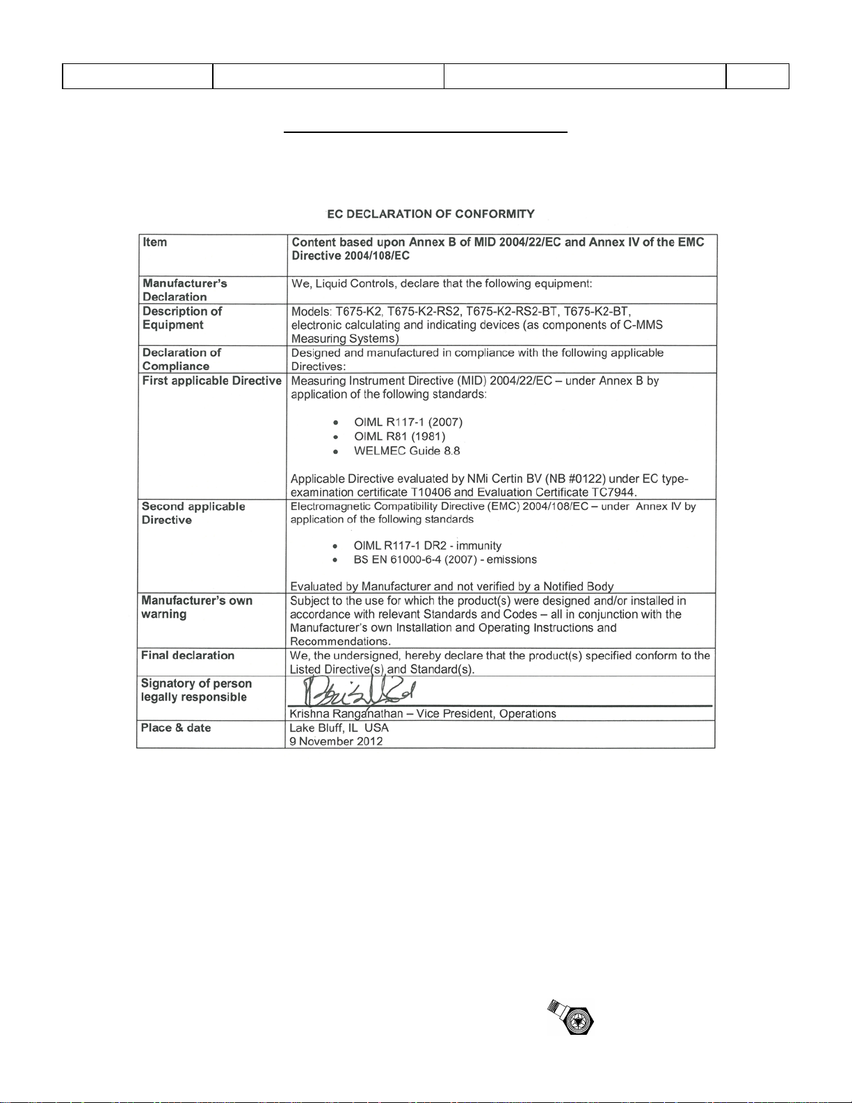
Sponsler, Inc.
Model T675 Flow Totalizer
Declaration of Conformity
Pg. 48
November 18, 2005
6. DECLARATION OF CONFORMITY
Declaration of Conformity
Rev A: Changed Company Information
Rev B: Updated for T675 Rev A hardware
Rev C: Updated for new T675 Rev A hardware (testing in November 2005)
CE DOC-T675C.doc Page 1 of 1
Sponsler
Page 52

Page 53

Page 54

© 2009
Pub. No. MN-T675-R10
(1/2013)
 Loading...