

Page 1

INSTALLATION & OPERATION
MANUAL
T650N SERIES
CRYOGENIC TRUCK TO TAL IZER
DOC #: MN-650.DOC
Page 2

Sponsler, Inc.
T650N Series Cryogenic Truck Totalizer
pg 2 DOC# MN-650
Page#
INTRODUCTION ........................................................................................................................... 3
MODEL T650N Dimensional Information ................................................................................... 16
TABLE OF CONTENTS
General ..................................................................................................................................... 3
Theory of Operation .................................................................................................................. 3
Testing ...................................................................................................................................... 3
Calibration ................................................................................................................................. 3
Temperature Compensation-Optional ....................................................................................... 3
INSTALLATION ............................................................................................................................ 4
Inspection ................................................................................................................................. 4
Physical .................................................................................................................................... 4
Electrical ................................................................................................................................... 4
Signal ........................................................................................................................................ 4
Field Termination ...................................................................................................................... 4
Initial System Start Up Procedure ............................................................................................. 5
Switch, Adjustment, and Display Descriptions .......................................................................... 5,6
CALIBRATION .............................................................................................................................. 6
Sensitivity .................................................................................................................................. 6
Calibration Factor...................................................................................................................... 6,7
“0-1” Function For Calibration ................................................................................................... 7,8
CALIBRATION FACTOR .............................................................................................................. 8
Field Correction ........................................................................................................................ 8
Calibration Factor-Change of Calibration Engineering Units ..................................................... 8
Temperature Compensation ..................................................................................................... 8,9
MODEL 820 TEMPERAT URE COMPENSATOR ......................................................................... 10
Introduction ............................................................................................................................... 10
Theory of Operation .................................................................................................................. 10
System Setup and Installation .................................................................................................. 11
Calibration ................................................................................................................................. 11
Model 820 Connection Diagram ............................................................................................... 12
SYSTEM TROUBLESHOOTING ................................................................................................... 13
Procedures ............................................................................................................................... 13
Troubleshooting Diagram .......................................................................................................... 14
MODEL T650N Internal Illustration ............................................................................................. 15
Page 3

Sponsler, Inc.
T650N Series Cryogenic Truck Totalizer
pg 3 DOC# MN-650
INTRODUCTION
General
The Model T650N Truck Totalizer provides flow totalization in any engineering unit. The totalized flow is displayed via
an accumulating 8 digit Liquid Crystal Display (LCD) electronic counter and an 8 digit resettable LCD.
Negatives previously associated with LCD’s - poor cold temperature performance, night clarity & condensation, which
is a byproduct of heaters, and incandescent lighting - have been eradicated with incorporation of a low temperature
coefficient LCD (-30
develop a precise, reliable totalizer.
Theory of Operation
The T650N initially amplifies & shapes the incoming pulses generated by the turbine’s response to flow. The amplified
pulse train is then scaled and divided to produce a totalized display in the desired engineering unit – gallons, liters,
pounds, SCF, m
sequence. A manual reset function is available if so desired.
Testing
A single switch “System Test” function enables maintenance personnel to quickly and effectively troubleshoot a system
failure, thereby reducing costly maintenance time. “System Test” provides a visual diagnostic indication of every
critical function of the T650N. With few exceptions, the system failure will be identified by the fault isolation LED’s of
the “System Test”.
Calibration
Field calibration is accomplished by incorporating a calibration factor based on the K-Factor of the turbine. A divider
switch provides a divisional increment of 10X from 1-10,000. The calibration factor is inserted using 4 BCD switches &
the 0-1 dip switch. The calibration factor range is .0001-1.9999. Verification of the electronics accuracy can be
accomplished by conventionally utilizing an external oscillator or by depressing the “System Test” switch which applies
a calibrated 500 Hz input signal to the system.
Temperature Compensation – Optional
A microprocessor based temperature compensation system designed to correct flow information based on product
temperature is available for use in the T650N. The Model 820 Temperature Compensator accommodates up to 8
different products (field selectable via a rotary switch) and accurately calculates the selected product density
acknowledging the non-linearity of the temperature probe and the product.
Installation of the Model 820 Temperature Compensator provides access to wireless I.R. communication for data
transfer to the Model SP824 portable ticket printer and provides an output for addition of a PCM-100 module for Pump
Control.
After market installation of temperature compensation requires minimal expertise and takes less than 15 minutes to
accomplish. By installing the 820 TC module, one connector to the 650 factoring board and the flip of a switch,
compensated totalization is accomplished.
o
C) and electroluminescent backlighting. The latest technological advances have been used to
3
, etc. The “power on reset” feature insures that the display is reset to zero during the initial po wer up
Page 4
Sponsler, Inc.
T650N Series Cryogenic Truck Totalizer
pg 4 DOC# MN-650
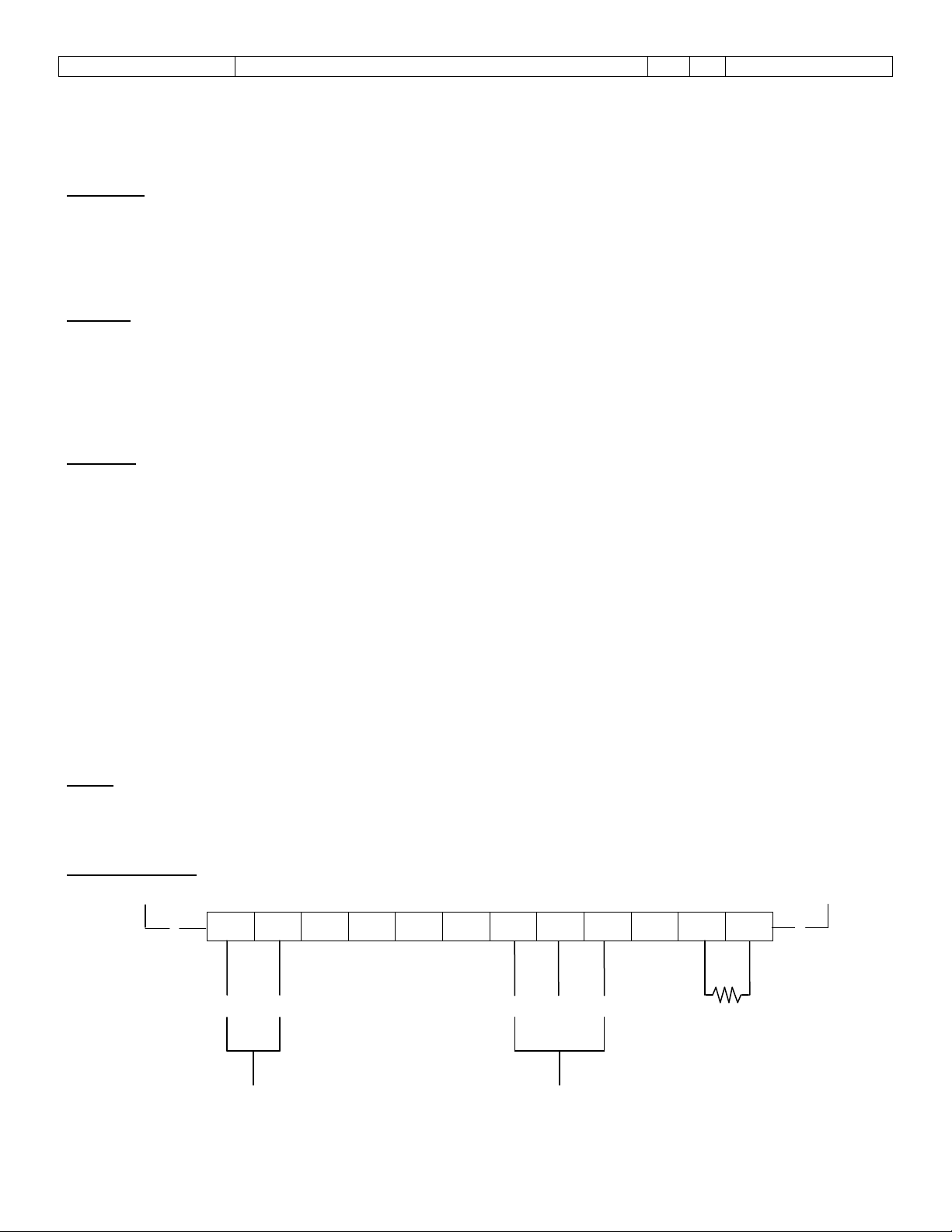
BLK
WHT
SHD
B
12 VDC
POWER
2-WIRE
RTD
INSTALLATION
Inspection
All units are completely assembled, tested and inspected at the factory prior to shipment. Upon receipt of the unit, a
visual inspection should be conducted to detect any damage that may have occurred during shipment. If the packing
case is damaged, notify the local carrier at once regarding his liability. A report should be made to the distributor.
Carefully remove the equipment from the packing and inspect for damaged or missing parts.
Physical
The T650N Flow Converter should be mounted as practically as possible taking into account display visibility,
accessibility, etc. Ideally the T650N should be securely mounted using ONLY the supplied shock mounts on a stand
positioning the Flow Converter 12-18” above the deck, clear of overhead pipes and as remote from the pump motor as
possible. Although the T650N enclosure integrity is watertight at manufacture, adherence to these guidelines will
significantly enhance the trouble-free operation of the unit.
Electrical
The T650N is designed to operate on the 12 VDC power system of the transport and is “polarity insensitive”. Both the
+ and – power inputs should be obtained in the pump control box. To facilitate testing without having to activate the
entire pumping system, + power input should be derived from the unswitched 12V input to the pump control box.
Every effort should be made to keep the proximity of the Flow Converter’s input power leads to the pump motor’s
winding leads as isolated as practically possible within the pump control box. In the event a transport doesn’t have a
pump control box, as is the norm in CO
front of the trailer connected to the 12 VDC accessory or Light Circuit.
DO NOT ATTEMPT TO OBTAIN POWER BY SPLICING INTO THE LIGHT CIRCUIT LOCATED NEAR THE METER:
LINE DROPS AND FLUCTUATIONS MAY AFFECT THE UNIT’S OPERATION.
DO NOT CONNECT A JUMPER FROM THE T650N ENCLOSURE TO THE TRAILER CHASSIS AND DO NOT
REPLACE THE SHOCK MOUNTS WITH SOLID “LOOK ALIKES” AVAILABLE IN HARDWARE STORES; THEY
HAVE SOLID MOUNTING STUDS AND ARE NOT ISOLATING STUDS AS PROVIDED BY THE SPONSLER
COMPANY.
Signal
The standard T650N signal cable is a 2 wire shielded cable with an MS3102 connector termination which is the
industry standard interface for 2 pole pickup coils. The shielding is single ended and should not be altered.
Field Termination
1 2 3 4 5 6 7 8 9 10 11 12
WHT
, 2 wires should be routed to the trailer’s power junction box located at the
2
BLK
WHT
BLK
A
SIGNAL
Page 5

Sponsler, Inc.
T650N Series Cryogenic Truck Totalizer
pg 5 DOC# MN-650
Initial System Start Up Procedure
Assure all Field Terminations are complete, correct and secure. Turn on the T650N and observe that 8 zeros are
displayed and the LCD back lighting is on. Depress res et if externa l reset opt ion was selecte d.
Refer to DWG. # SCI-T650N-REV C-TC-INT
Open the T650N enclosure and depress “System Test” S9. All LED indicators of the 10 position bar graph D1-D10
should be illuminated except D3 if “1” is selected by “0-1” Switch S2. Also observe that both the LCD counters
increment equally. D4, 5, 6, & 7 will blink. Each LED indicates a specific T650N function. The indicators are
extensively discussed in the Description Section and in the Troubleshooting Section which should be referenced in the
event of a failure of the T650N.
Switch, Adjustment, and Display Descriptions
S1 - Power Switch: 3 Amp DPDT; switches fused input power to the logic circuits of the factoring and
display boards.
S2 - “0-1” Switch: 2 position D.I.P.; permits increased calibration accuracy when the calibration factor
begins with a ‘1’ such as .015979 (Refer to example #3).
S3-6 - Factoring Switches: 10 position (0-9) BCD rotary; inserts the desired calibration factor digitally with S3 as
the MSD & S6 as the LSD.
S7 - Divider Switch: 5 position rotary; provides the proper divider for decimal point placement in the
calibration factor.
Position 1=1, 2=10, 3=100, 4=1000, 5=10000
S8 - Reset Switch: Single pole, momentary pushbutton; resets display and all logic circuits when
depressed and released.
S9 - System Test: Single pole, momentary pushbutton; activates LED bar graph and injects 500 Hz signal
to increment LCD counters while depressed.
S10 - Display Test: Single pole, momentary pushbutton; injects signal to increment large LCD while
depressed.
S11 - Display Decimal Point: Display Blanking & Backlight Control: 2 position, 4 pole D.I.P.
S11-1: displays 10ths Decimal Point when in ‘1’ position
S11-2: displays 100ths Decimal Point when in ‘2’ position
S11-3: display blanks when in ‘3’ position and power “OFF”
S11-4: extinguishes backlight when in ‘4’ position and power “OFF”.
S12 - TC Selector: 2 position D.I.P.; permits by-pass of the temperature compensation module. Positions
0=w/o TC; 1=TC incorporated.
R1 - S ensitivity Adjustment: Single turn potentiometer; establishes input signal amplitude required to initiate the
count sequence.
CCW = minimum sensitivity CW = maximum sensitivity
Page 6

Sponsler, Inc.
T650N Series Cryogenic Truck Totalizer
pg 6 DOC# MN-650
Engineering Units
K-Factor
Bar Graph - 10 position LED; activated while S9 (system test) is depressed to indicate status of specific functions
of the T650N circuitry.
D1 - normally illuminated; extinguished if either the pickup coil or the signal cable shorts.
D2 - normally illuminated; extinguished if either the pickup coil or the signal cable opens.
D3 - illuminated if S2 is in “0” position; extinguished if S2 is in “1” position.
D4 - normally flashing; nonflashing if mechanical counter output signal is absent.
D5 - normally flashing; nonflashing if factoring board output signal is absent.
D6 - normally flashing; nonflashing if display board oscillator is not functioning.
D7 - normally flashing; nonflashing if system test oscillator is not functioning.
D8 - normally illuminated; extinguished if 12 volts is absent.
D9 - normally illuminated; extinguished if 5 volts on factoring board is absent.
D10 - normally illuminated; extinguished if 5 volts on display board is absent.
D11 - Power indicator, LED; illuminated if switched fused input power is present.
D12 - TC Range Alarm, LED; illuminated if temperature compensation is incorporated and temperature for
the selected product is out of range.
J5 - Jumper: installed if external manual reset is incorporated.
J6 - Jumper: installed if power on reset is incorporated.
CALIBRATION
Sensitivity
The Sensitivity adjust (R1) should be adjusted at the lowest expected flow rate. Turn R1 completely counterclockwise;
slowly adjust R1 clockwise until the display increments; then increase R1 slightly clockwise again. In the normal R1
position, the arrow indicator will be in the 11 o’clock position.
Calibration Factor
The Calibration Factor is derived by taking the reciprocal of the meter’s “K-Factor” (pulses per gallon or other
engineering unit).
It is desired that zero not be dialed as the first digit on the factor switches. The CF, in most cases, will start with at
least one zero. The divider switch (S7) on the factoring board will allow dividing by 1, 10, 100, 1000, or 10000 to move
the decimal the required digits.
C.F. =
Page 7

Sponsler, Inc.
T650N Series Cryogenic Truck Totalizer
pg 7 DOC# MN-650
S7 POSITION
DIVIDER
500 X Time In Seconds X Calibration Factor
Divider
500 X 120 X .4348
100
Hz X Time In Seconds X Calibration Factor
Divider
(41,381,600 X .1257)
for a difference of 166.7 SCF
10
1
2
3
4
5
Example #1: K-Factor = 230 pulses per gallon
Engineering Units = Gallons
1/230 = .0043478
Set S7 in Position 3 (100 divider; moves decimal right 2 places)
Set S3 at 4, S4 at 3, S5 at 4, S6 at 8 (Rounding 4
Set S2 on “0” position
Accuracy: Using the “System Test” the electronic accuracy can be verified incorporating the following
formula for a timed test.
QTY. Displayed =
Example #2: Time = 2 Minutes (120 sec.), CF = .4348, Divider = 100
QTY. Displayed =
1
10
100
1000
10000
(does not move decimal)
(moves decimal right 1 place)
(moves decimal right 2 places)
(moves decimal right 3 places)
(moves decimal right 4 places)
th
digit)
= 260.88 = 261
Universal Formula –
QTY. Displayed =
“0-1” Function for Calibration:
The “0-1” function provides a greater degree of accuracy when totalization encompasses a large quantity such as SCF
produced in a 24 hour period.
Example #3: Assume a turbine flowmeter has a K-Factor of 79.58 pulses per SCF and a product demand of
520,000 SCF is the customer’s daily usage.
A delivery of 520,000 SCF = 41,381,600 total pulses (520,000 X 79.58).
C.F. = 1/79.58 = .012566
Without the “0-1” function
S7 in Position #2 (10 divider; moves decimal right 1 place)
S3 at 1, S4 at 2, S5 at 5, S6 at 7 (rounding the fourth digit)
S2 in “0” position
The meter would indicate a total quantity of 520,166.7 SCF
Page 8

Sponsler, Inc.
T650N Series Cryogenic Truck Totalizer
pg 8 DOC# MN-650
(41,381,600 X .2566) + 41,381,600
for a difference of 1 SCF
Actual Total
Meter Total
3.785
230
500 X Time in Seconds X CF
Divider
(
)
Incorporating the “0-1” function:
S7 in Position #3 (100 divider; moves decimal right 2 places) Decimal must move to the right of the 1
digit.
S3 at 2, S4 at 5, S5 at 6, S6 at 6
S2 in “1” position
The meter would indicate a total quantity of 520,001.2 SCF
100
CALIBRATION FACTOR
Field Correction
To adjust the calibration factor to reflect the actual response of the turbine to the operating conditions, apply the
following formula:
New Calibration Factor =
Example #4: Actual Total = 50
Meter Total = 52
C.F. = .4000
50/52 X .400 = New Calibration Factor
.9615 X .4000 = .3846
Insert .3846 into S3 – S6 respectively
In the above example .9615 denotes that the meter is operating 3.85% fast & multiplying the present calibration factor
(.4000) by the ratio of Actual Total: Meter Total (.9615) reduces the calibration factor 3.85%.
Calibration Factor – Change of Calibration Engineering Units
Assume that rather than gallons, liters are the desired engineering unit.
Example #5: K-Factor = 230 pulses per gallon
Liters = 3.785 per gallon
= Calibration Factor
= .016456 for display of liters
Set S7 at 3 (100 divider; moves decimal right 2 places)
Set S2 at 1 (incorporates “0-1” function)
Set S3 at 6, S4 at 4, S5 at 5, S6 at 6
Temperature Compensation:
The temperature compensator is discussed in detail in the attached Model 820 Supplement. The Model 820
Temperature Compensator digitally converts a resistive temperature representation to a density correction factor that
corrects for variations in mass related to temperature. Incorporation of the following formula provides a means to
verify field accuracy.
X Calibration Factor
Quantity Displayed =
X (Temperature Correction Factor)
Page 9

Sponsler, Inc.
T650N Series Cryogenic Truck Totalizer
pg 9 DOC# MN-650
(500 X 60 X .5279)
100
(15837)
100
=
158.37
X (1.0529)
Hz X Time in Seconds X CF
Divider
(
)
Use the “System Test” S9 (Injects 500 Hz signal).
Example #6:
Calibration Factor = .5279 Time = 60 seconds
Divider = 100 T.C. Factor = 1.0529
Substituting: Quantity Displayed =
=
= 166.7
The Temperature Correction Factor (T.C.F.) is referenced at the Normal Boiling Point (NBP). The example above
indicates that the product temperature is below the NBP in that the T.C.F. > 1. Likewise, if the product temperature is
above the NBP, the T.C.F. will be < 1.
Universal Formula:
Quantity Displayed =
X (1.0529)
X (1.0529)
X (Temperature Correction Factor)
Page 10

Sponsler, Inc.
T650N Series Cryogenic Truck Totalizer
pg
10
DOC# MN-650
DELAY TIME
(minutes)
LOX & LIN
10
ALL OTHERS
1
LOX, LIN, & LAR
12
M820-VO1-7
ALL PRODUCTS
5
ANY OTHER VERSION HAS NO TIME DELAY BUILT IN
MODEL 820 TEMPERAT URE COMPENSATOR
Introduction
The Model 820 Temperature Compensator is a highly sophisticated electronic temperature compensation system
designed to correct flow information based on product temperature. Inserted between the signal source and recording
electronics, the temperature compensator will automatically add or subtract pulses from the pulse train based on
temperature of the product being delivered. The Model 820 is designed to accommodate up to 8 different products
(field selectable via a rotary switch) with the density and non-linearity of the temperature probe and each product being
acknowledged. Data transfer via wireless (IR) communications is available to print product selection, temperature,
correction factor and accumulated corrected total on the Model SP824 Portable Ticket Printer.
Theory of Operation
As product flows through the pipeline, a turbine located in the product spins and electrical pulses are generated and
sent to the temperature compensator. The number and frequency of these pulses corresponds to the amount of
product flow and the flow rate.
As the product in the pipeline heats or cools, the density and volume of the product change. When the volume of
product changes, the turbine spins faster or slower since the turbine flowmeter is a volumetric measuring device even
though the AMOUNT (measured by weight) of product is not changed. Model 820 performs its function first by
amplifying and conditioning signals from a pickup coil or other small signal device. The temperature of the product is
then read via an RTD temperature probe. Model 820 then adds or subtracts incoming pulses based on the
temperature/density of the product and the product’s correction curve.
As long as the product flowing past the temperature sensor is within range for the product, the temperature
compensator will automatically correct for the density of the product. If the product is not within the correct
temperature range, or the temperature probe fails, the compensator will turn on the alarm LED and modify the
temperature correction factor (TCF).
The TCF is modified based on the jumper installed at the jumper option block of the 820 (Ref. Drawing SCI-820CONN-VOL-9-01 & Table “OPTION JUMPER” on the next page). If no jumper is installed, the correction factor will be
set for no compensation (TCF = 1.00). If the “B” jumper is installed, the 820 will stop accepting incoming pulses during
alarm condition, resulting in no count during an alarm condition. If the “C” jumper is installed, the compensator reverts
to ‘alarm’ temperature and corresponding TCF for the selected product (Ref the ‘Model 820 EPROM’ table for a listing
of products, temperature compensation range, and default alarm temperature).
The pump control output is used in conjunction with the PCM-100 module to disable the pump when the product is
above the proper temperature for delivery. If the 820 detects a complete temperature probe failure (temperature
reading above 200
after the temperature probe detects that the product is within the correct temperature range for delivery may be
activated by installing jumper ‘D’. This enabled delay allows the entire system to reach temperature before delivery is
allowed. Once the pump is enabled, the product temperature may go out of range for 10 seconds before the pump is
disabled. Once the pump is disabled, the initial delay time will be imposed before the pump is again enabled.
The delay times are based on the EPROM version installed on the Model 820 and the product selection. The following
table lists each version and the associated time delays (The EPROM installed on the 820 will be labeled with the
version).
o
C), the pump will be enabled so as not to prevent delivery. A timer to continue to disable the pump
EPROM PRODUCT
M820-VO1-9
M820-VO1-8
LAR 15
ALL OTHERS 5
Page 11

Sponsler, Inc.
T650N Series Cryogenic Truck Totalizer
pg
11
DOC# MN-650
POSITION
PRODUCT
LOW LIMIT
REF TEMP
ALARM TEMP
HI LIMIT
0
Oxygen
-200.00
-183.11
-168.00
-140.50
1
Nitrogen
-210.00
-195.930
-182.00
-155.30
2
Argon
-189.00
-186.046
-168.00
-140.50
3
CO2
-40.050
-16.388
-6.30
-6.30
4
N2O
-51.087
-34.679
15.30
15.30
5
Calif. CO2
-40.00
-25.817
-7.00
-7.00
6
MAPP
-17.871
15.384
50.50
15.50
7
LPG
-40.00
15.384
49.50
49.50
9
Self test
Jumper
Description
A
(*do not install) Momentarily shorted in probe calibration mode starts the dip switch
verification test.
B
C
When the alarm LED is on... If the jumper is installed the compensator reverts to the
1.00) and will output the actual temperature without modification.
D
System Setup and Installation
The Temperature Compensator has been calibrated for the RTD and tested in the factory. Once the unit is installed,
the product selector switch must be set to the correct position for the product being delivered.
The following table summarizes the various positions of the product selector switch and the corresponding product.
MODEL 820 OPTION ‘IC’ EPROM
8
The following table summarizes the option jumpers and their functions. NOTE: Only one jumper should be installed!
Calibration
To calibrate the unit, first set the product selector switch to position 8 (calibrate). Next replace the temperature probe
with a 100 ohm .1 resistor and observe the (-) and (+) LED’s on the PCB. If the (-) LED is on, turn the calibrate pot
clockwise until the LED goes off. If the (+) LED is on, turn the calibrate pot counterclockwise until the LED goes off.
Once both LED’s are off, the unit is calibrated properly and is ready for use.
NOTE: Be sure to set the product selector switch back to the correct position for the product being delivered
Calibrate &
switch test
When this jumper is installed the unit will not totalize if the alarm LED is on.
‘alarm’ temperature and corresponding TCF for the product selected. If the ‘C’ jumper is
not installed, the compensator will set the correction factor for no compensation (TCF =
When jumper is installed the pump control time delays will be activated.
OPTION JUMPERS
Page 12

Sponsler, Inc.
T650N Series Cryogenic Truck Totalizer
pg
12
DOC# MN-650
IR INTERFACE
SERIAL PORT
S
J4
J3
PROBE CALIBRATION POT
P0
+LED
- LED
ALARM LED
SIGNAL INPUT LED
SIGNAL OUTPUT LED
J2
D0D2D3
D4
D1
FUNCTION
ALARM OUTPUT GROUND
TEMP PROBE
TEMP PROBE
SIGNAL INPUT (SIG 2)
SIGNAL INPUT (SIG 1)
ALA RM O UTPUT
OUTPUT GROUND
OUTPUT SIGNAL
8
7
6
5
4
3
2
1
J2
-
+
DC POWER
D
C
B
A
PRODUCT SE L ECTOR
0 = LOX
1 = LIN
2 = LAR
3 = LCO
2
4 = N2O
5 = CCO
2
6 = MAPP
7 = LPC
8 = CALIBRATE
PROBE
OPTION JUMPERS:
B = INS TAL L F O R NO COUNT
IN ALARM
C = INSTALL TO REVERT TO
“ALARM” TEMPERATURE
AND TCF FOR PRODUCT
D = INSTALL TO ACTIVATE
PUMP CUTOUT TIME
0
DATE DRAWING NUMBER
SPONSLER CO., INC.
MODEL 820 CONNE CTION DIAGRAM VOL-9 OPTIONS
7-9-96
SCI-820-CONN-VOL-9-01
PUMP CONTROL
OUTPUT
MODEL 820
CURVE IC
M820-VO1-9
EPROM
NOTES:
“C” JUMPER SHOULD ALWAYS BE INSTALLED TO
ENABLE SP825 DATA TRANSMISSION
“B” & “D” MAY BE INSTALLED AS NEEDED TO ENABLE
FUNCTIONS AS LISTED
12/01 ADDED NOTES
Page 13

Sponsler, Inc.
T650N Series Cryogenic Truck Totalizer
pg
13
DOC# MN-650
SYSTEM TROUBLESHOOTING
Procedures:
When a failure is believed to exist, the following procedure will aid in expediting the isolation of the failure.
1. Check all wiring for secure and accurate connections. Ref. DRAWING # T650NIR-1
2. Check that sensitivity (R1) setting is mid-range (11 o’clock), and depress S9. Observe all LED’s
and the displays.
3. Follow the troubleshooting diagram (next page) for the following:
SYMPTOM
No Display
Display “ON” – No Count
Display Counts – No Accumulative Count
This test is designed to troubleshoot the 820 Temperature Compensator after the 650D and 650F Boards have
been proved functional (unit functions correctly when S12 is in W/O TC position).
Refer to Drawings: SCI-820-CONN-VOL-9-01
T650NIR-1
Troubleshooting Diagram
Preliminary Checks:
1. Probe Cable: Check continuity between Pin A and W HT wire; Pin B and BLK wire.
Check NO SHORT between Pin A and Pin B or between Pin A or Pin B and the
connector.
Insure that the probe cable wires are securely attached at J1-11 and J1-12.
2. Probe: Check resistance between Pin A and Pin B
If the RTD is at ambient temperature, resistance range 100 to 110
If the RTD is immersed in liquid product at delivery temperature:
LOX resistance range 18 to 42
LIN resistance range 16 to 37
LAR resistance range 23 to 42
CO
If the resistance reading is NOT within the specified range, replace the RTD
3. Insure that interconnect wiring harness is installed properly and securely at 650F J2-A and 820 J2 and
J4.
4. Insure that the 820 Product Selector Switch (SO) is in proper position for product being measured.
5. Check placement of jumper on 820 PCB. Ref DRAWING # SCI-820-CONN-VOL-9-01. If installed at
‘B’, the unit will not count while the temperature is out of range for the selected product. The alarm LED
will be “ON” if the temperature is out of range.
6. Set S12 in W/TC position. Turn Power “ON”. Display is “ON”; D11 is “ON”; D12 is “OFF” (Probe is
immersed in liquid product). Depress S9. If D3 and D4 don’t flash (unit does not count), proceed to
Troubleshooting Chart (next page).
resistance range 84 to 96
2
Page 14

Sponsler, Inc.
T650N Series Cryogenic Truck Totalizer
pg
14
DOC# MN-650
GO TO STEP 15
NO GO
1) SW ITCH S12 TO W/T. C.
2) DEPRESS S9 FOR 15 SEC
OBSERVE DISPLAY N2 = 53 COUNTS
O2 = 58 COUNTS
AR = 57 COUNTS
CO2 = 59 COUNTS
CCO2 = 57 COUNTS
REPLACE
650F & D
NO GO
1) SW ITCH S12 TO W/O T.C.
2) SET S3, 4, 5, 6 TO 7777
3) DEPRESS S9 FOR 15 SEC.
OBSERVE S8 DISPLAYED
12
NO GO
REPLACE
650F & D
REPLACE T.C.
SWITCH S12 TO W/O T.C., DEPRESS S9
OBSERVE DISPLAY COUNTS
NO GO
NO GO
GO
11
REFER TO TURBINE
ASSY. DRAWING
REBUILD
TURBINE
'COUNTS'
OPEN DISCHARGE VALVE PERMITTING VAPOR
BLOW BY - OBSERVE DISPLAY COUNTS
SYSTEM
COUNT
10
DEPRESS S9 - OBSERVE
DISPLAY COUNTS
REPLACE
PROBE CABLE
'ON'
D0 & D2 'ON' PROBE CABLE SHORTED
D0 & D3 ‘ON’ PROBE CABLE ‘OPEN’
9
T.C. ASSY
DISCONNECT RTD & CONNECT TEMP RANGE
PLUG - OBSERVE D0, D2, D3 ‘OFF’
(AL) (-) (+)
8
REPLACE
650F & D
D6, D7 'OFF' (NOT FLASHING)
D8, D9 ‘OFF’
SWITCH S1 2 TO W /T.C.
REPLACE T.C.
'FLASHING
'
NO GO
REPLACE
650F & D
7
D4. D5 'OFF' (NOT FLASHING)
1) SW ITCH S12 TO W/O T.C.
2) DEPRESS S9, OBSERVE D4,
D5 ‘FLASHING’
REPLACE
650F & D
REPLACE
P/U COIL
REPLACE
SIGNAL CABLE
'OFF'
NO GO
NO GO
'ON'
6
5) CONNECT J1
6) TURN POWER ‘ON’
OBSERVE D1, D2 ‘ON’
4) CONNECT P/U COIL
J1-7 (WHT) → J1-8 (BLK)
1800-2100Ω WARM
AS LOW AS 250Ω COLD
J1-9 (SHD) → J1-7 OR 8 = ∞Ω
D1,2 'OFF'
1) TURN POWER ‘OFF’
2) DISCONNECT J1
3) DISCONNECT P/U COIL
J1-7 (WHT)
→ PIN ‘A’ = 0 Ω
J1-8 (BLK) → PIN ‘B’ = 0 Ω
J1-9 (SHD) → J1-7 or 8 = ∞Ω
J1-7 (WHT) → J 1-8 (BLK) = ∞Ω
NO GO
5
DEPRESS S9, OBSERVE
D1-D10 ‘ON’ OR FLASHING
DIAGNOSTIC LED'S
17
18
16
GO TO STEP 5
OK
REPLACE T.C.
BLOWN
DISCONNECT J2
OBSERVE FUSES
FUSES
BLOWN
O.K
YES
CHANGE DEFECTIVE FUSE
REPLACE S1
POWER SWITCH
NO
CHECK J1-5,6
FOR 12 VDC
BLOWN
GO
CHECK FUSES
F1 & F2
'OFF'
POWER CIRCUITS
REPLACE
650F & D
'ON'
DEPRESS S9, OBSERVE
D8, 9, 10 ‘ON’
4
3
2
1
'
OFF'
'ON'
TURN POWER 'ON' & OBSERVE THAT
THE DISPLAY IS EITHER ‘ON’ OR ‘OFF’
ON TC ASSY CHECK THAT: JU7 INSTALLED,
PRODUCT SELECTOR IN CORRECT POSITION
& IF EQUIPPED SENSITIVITY=11 O’CLOCK
CHECK SENSITIVITY ADJUST
ON T650F=11 O’CLOCK
CHECK AND SECURE ALL
ELECTRICAL CONNECTIONS
‘IT DOESN'T WORK"
1) CONNECT J1
2) CLOSE & SECURE LID
NO GO
REPLACE
RTD
15
1) TURN POWER ‘OFF’
2) DISCONNECT J1
3) DISCONNECT TEMP RANGE PLUG
4) CONNECT RTD
J1-11 (WHT) → J1-12 (BLK) =
114.4Ω = 98.6 °F
20.25Ω = -320 °F
25.75Ω = -298 °F
24.50Ω = -303 °F
90.0Ω = -10° F
RTD TES T
BASIC CONCEPTS
1) DISPLAY ‘ON’
2) ALL DIAGNOSTIC LEDS ‘ON’ OR ‘FLASHING’
3) ALL T.C. RANGE LEDS ‘OFF’
4) DISPLAY COUNTS
5) SYSTEM ACCURACY
6) VAPOR BLOW BY GENRATES COUNT
T.C. 100Ω CALIBRATION PROCEDURE
A) DISCONNECT RTD
B) INSTALL TEMP CAL PLUG
C) SET PRODUCT SELECTOR ON T.C. TO #8
D) CALIBRATION ADJUSTMENT D2 ‘ON’ (-) ADJUST UNTIL D2 ‘OFF’
D3 ‘ON’ (+) ADJUST UNTIL D3 ‘OFF’
E) DISCONNECT TEMP CAL PLUG
F) CONNECT RTD
G) RETURN PRODUCT SELECTOR ON T.C. TO
CORRECT PRODUCT
0 = O
2
1 = N
2
2 = A
R
JU7
D0
D2
D3
TEMPERATURE
COMPENSATOR
BOARD
SENSITIVITY
W/O TC
W/TC
SYSTEM TEST
CW
FACTORING BOARD
F1
S12
R1
S9
J2-A
D1-D10
J3-A
F2
J1
S3S4S5
S6
REV C
123456789
10
11
12
PROCEED TO
STEP FOR
OFF LED
'ON' OR FLASHING
PROCEED TO
STEP 9
TROUBLESHOOTING DIAGRAM
REPLACE T.C.
14
13
COUNTS
ACCURACY
TEST
GO
GO
‘OFF’
PRODUCT
SELECTOR
0 - 0
2
1 - N
2
2 - A
R
CAL 100Ω ADJUST
(ALARM)
(-)
(+)
Page 15

Sponsler, Inc.
T650N Series Cryogenic Truck Totalizer
pg
15
DOC# MN-650
Page 16

Sponsler, Inc.
T650N Series Cryogenic Truck Totalizer
pg
16
DOC# MN-650
SPON SLER C O . , I NC .
SPONSLER CO., INC.
MFG DATE
Dimensional Information
4 1/2"
11 3/4"
6"
MODEL T650N
TC RANGE
ALARM
POWER
FLOW MEASURING DEVICES AND CONTROLS
2363 SANDIFER BLVD., W ESTMINSTER S.C. 2 9693, 864-647 -2065
9"
POWER
©2009
Pub. No. MN-650-R1
(09/09)
FLOW MEASURING DEVICES AND CONTROLS
2363 SANDIFER BLVD., WESTMINSTER SC 29693
POWER
MODEL
SERIAL #
10 7/8"
 Loading...