

Page 1

INSTALLATION & O PERATION
MANUAL
T350N-P
Truck Totalizer/Printer
Page 2

Sponsler, Inc.
T350N-P Truck Totalizer/Printer
pg. 2
Doc# MN-T350N-P
CONTENTS
INTRODUCTION/THEORY OF OPERATION 1
INSTALLATION 2
SWITCH/ADJUSTMENT DESCRIPTION 3
OPERATION 4
CALIBRATION 4,5
FIELD CORRECTION 5
TROUBLE SHOOTING 6,7
TEMPERATURE COMPENSATION 8,9
PROGRAMMING MESSAG E S 10
CONNECTION DEAGRAM RLC 113 11
CONNECTION DIAGRAM FOR TEMP. COMP. BOARD 12
LOCATION DIAGRAM 13
PAPER INSTALLAT ION 14
DIMENSIONS 15
Page 3

Sponsler, Inc.
T350N-P Truck Totalizer/Printer
pg. 3
Doc# MN-T350N-P
INTRODUCTION
A. GENERAL
The model T350N-P Totalizer/Printer di s plays flow d irectly in engine ering unit s .
The model T350N-P utilizes the latest in circuitry design and components. The
circ uitry is microprocess or bas ed and perfor ms th e scaling and count i ng w ith only
one main circuit board.
The totalized flow is displayed on a liquid crystal display (LCD), and is printed on
standard calculator type thermal paper.
B. THEORY OF OPERATION
Model T350N-P is used in conjunction with frequency or pulse generating source
such as a turbine flowmeter or other pulse flow transducers. The totalized flow
disp l ay m ay b e c alibrated t o indicat e mos t an y uni t of vol u m e, gals., li ters, scf m. ,
etc. Standard units are factory-calibrated for a standard flowmeter in ga llons. If
additional calibration is necessary, the dividing factor may be changed by
adjustment of internal factoring switches located on the main circuit board.
The Model T350N-P dis p l ays total flow vi a an LC D dis play an d th er m al printin g
device. Printing of th e dis p layed tot al is accomplished by pus h in g the PRINT
switch. The printer will show a two-lin e m essage, product d eliver y, ti m e and
date, stating count, and finished count. There is a space provided for an
authorized signature. When the printer stops, the display will zero and be ready
to acc ept a new c ount. If th e PRIN T sw itc h is activat ed d ur i ng a d eli v ery, the
coun t will st op and the print er wi ll pri nt th e n ew inform ati on.
Power Consumption – 12V Unit
Printing – 1.9 Amp
Normal – 0. 5/ 0.7 Amp
Page 4
Sponsler, Inc.
T350N-P Truck Totalizer/Printer
pg. 4
Doc# MN-T350N-P
INSTALLATION
Inspection
All units are completely assembled, tested and inspected at the factory prior to
shipment. Upon receipt of the unit a visual inspection should be conducted to
detect any damage that may have occurred during shipment.
Physical
The T350N-P s hould be m oun t ed as practicall y as poss ible tak in g into acc oun t
disp l ay vis i bil ity, accessibi lit y, etc. Ideal ly the T350N -P should be securely
mounted using
ONLY
the supplied shock mounts on a stand positioning the unit
12-18” ab ove t h e d eck, clear of overhead pipes and as remote form the pump
mot or as pos s ib le. Adher ence to thes e gu id el ines will si gnificantly en hanc e the
trouble free operation of the unit.
Electrical
The T350N-P is designed to operate on the 12 VDC power system of the
transport and is “polarity insensitive”. Both the + and – power in puts s hould be
obtained in the pump control box. To facilitate testing without having to activate
the entire pumping system + input power should be derived from the unswitched
12 V input to the pump control box . Every effort should be ma de to keep the
T350N-P isolated as much as possible within the pump control box. In the event
transport doesn’t have a pump control box, as is the norm, 2 wires should be
routed to the trailer power junction box located at the front of the trailer. Do not
attempt to obtain power by splicing into the light circuit located near the
meter. Line drops and fluctuations may affect the operation. Additionally –
not connect a jumper from the T350N-P enclosure and the trailer
do
repl ace the ch oc k mou nts with so lid “Look a-likes”
chassis and do
not
available in hardware store. They have solid mounting studs and are not
isolating studs as provided by the Sponsler Company.
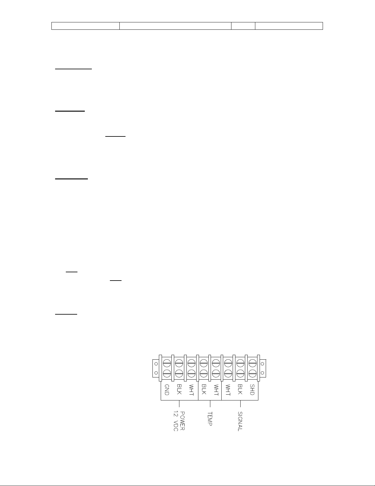
Signal
The standard T350N-P signal cable is a 2 wire shielded c abl e w ith a MS3102
connector termination which is the industry standard interface for 2 pole pickup
coils. The shielding is single ended and should not be altered.
Field Termination:
TBI Drawing
Page 5

Sponsler, Inc.
T350N-P Truck Totalizer/Printer
pg. 5
Doc# MN-T350N-P
SWITCH & ADJUSTMENT D ESCRIPTIONS
Power Switch: 3 amp DPDT, switches fused power to the
lo gic ci rcuits of the unit.
Print Switch: 3 amp Momentary Toggle Switch, initiates print
cycle.
Sensitivit y Adju stm ent: Single turn potentiometer establishes required
input signal amplitude to initiate the count
sequence.
Displ ay Bi as A dj ustmen t: Single turn potentiometer establishes the
contr as t of th e dis play.
S0- S3-Factoring Switches: 10 positi on (0-9) BCD rotary, inserts the
desir ed c alibration fact or di git al ly with S0 as
the LSD and S3 the MSD.
S4-Pre-sca le S witc h: 10 posi ti on (0-9) BCD rotary, provides the
proper divider for decimal poi nt placement in
the Calibration factor. Position 1=1; 2=10;
3=100; 4=1000; 5=10000
S4-Position 9 = Self Test: Allows the totalizer’s microprocessor to
pe rform internal tests on the built - in RAM and
ROM.
S5-Decimal Point Selection: 10 posi ti on (0-9) BCD rotary, position
corresponds to the num ber of digi ts to the right
o f the decimal point.
Signal Input LED: Flashes to indicate that input signal is present
(at high er frequenc i es th e LED will appe ar t o
be constantly illuminated.)
A & B LED: Flash during ‘self-test’ to den ote that
microprocessor is testing.
VR101: Single turn potentiometer, adjusts darkness of
print.
Page 6

Sponsler, Inc.
T350N-P Truck Totalizer/Printer
pg. 6
Doc# MN-T350N-P
CALIBRATION
Sensitivity
The Sensitivity adjusts (R1) should be adjusted at the lowest expected flow rate.
Turn R1 completely Counter-Clockwise then slowly adjust R1 Clockwise until the
display increments then increase R1 slightly Clockwise again. In the nominal R1
position the arrow indicator will be in the 11 o’clock position.
Calibrati on Fa ctor
The Calibration Factor is derived by taking the reciprocal of the meter’s “KFact or” (pulses per gal lon or other d esi red engin eering un it) .
C.F. =
Engineering Units
K-Factor
It is desired that ze ro not be dialed as the first digit on the factor switches. The
CF, in most cas es, will start with at l eas t on e z er o. The multip li er s wi tc h on th e
fact oring board wil l allow multipl yin g b y 1, 10, 10 0, 10 00, or 10000 to move t he
decimal the required digits.
S4 posit i on Multiplier
0 1
1 10
2 100
3 1000
4 10000
Example 1: K-Factor = 230 pulses per gallon
Engin eering un it s des ir ed = gallons
C.F. = 1/K = 1/230 = .00434782
Multiplier = 100; S4=2,
Fac tor S3=4, S2 =3, S1= 4, S0=8
The electron ic acc uracy can be verifi ed i ncorporating t h e f ollow i ng f or mu la for a
timed tes t:
Total Displayed = Frequency X Time in seconds X C.F.
Example 2: C.F. = .004348
Time = 1 min = 60 seconds
Frequency = 500 Hz
Total = 50 0 X 6 0 X .004348
Total = 130.4 = 130
Page 7

Sponsler, Inc.
T350N-P Truck Totalizer/Printer
pg. 7
Doc# MN-T350N-P
For high er res oluti on (r ead ing in gal l ons and tenths , gal lons and h un dredths ,
etc.) mu lt i pl y b y 10 f or t enths ; by one f or hu ndr edths. Th e nu m b er dialed into
dipswitch S5 corresponds to the number of digits to the right of the decimal point.
Example:
Flowmeter “K” Factor = 230
CF= .0043 48
Desired disp l ay = gal lons and tent hs
Multiply by = .04348
S4 = 1
Fact or S wi tc h es = 43 48; S3 = 4, S2 = 3, S1 = 4, S0 = 8
Decimal point = S5 = 1
Field Correction
To adjust the calibration factor to reflect the turbines actual response to the
operating conditions apply the following formula:
New Calibration Factor =
Actual Total
X Calibration Factor
Meter Total
Example #2:
Actual Total = 50
Meter Total = 52
C.F. = .004348
50/52 X .004348 = New Calibration Factor
.9615 X .004348 = .0041806
Insert 4181 into S3 – S0 respectively
In the ab ove e xam p le .9615 den otes that t h e m eter is op erating .38 5% fast and
multiplying the present cali bratio n factor (.004348) by the ratio of Actual Total:
Meter Total (.9615) reduces the calibration factor 3.85%.
Calibrati on Fa ctor – Change of Calibration Engineering Units
Assume that rather than gallons, liters are the desired engineering unit.
Example #3:
K-Fac tor = 230 pul ses pe r gallon
Liters = 3.785 per gallon
= Calibration Factor
3.785
230
.0164 6 = C ali bration F actor for display of liters
Page 8

Sponsler, Inc.
T350N-P Truck Totalizer/Printer
pg. 8
Doc# MN-T350N-P
TOUBLE SHOOTING
PROBLEM
Unit not working (No Display Light)
A. Power Cable broken
B. Battery Low
C. Defective power switch
D. Blown fuse
E. Reversed p ow er wi r es
Unit not working (Display Light On)
A. Check signal wire for breaks
B. Check sensitivity control
C. Che ck pickup coil
D. Check printed circuit board plugs to make sure they are mated securely.
E. Look for br ok en wir es ins ide of elec tronic enc l os ure.
F. Check SWI (see draw. 1) to be sure it is in position 0-4.
Unit continues to blow fuses
A. Shorted power cable
B. Faulty electronic board
C. Power surges
Printer does not feed paper
A. Pow er not t ur n ed on
B. No paper installed
C. Paper not feedi ng into printer
D. D efecti v e p ri n t switch
Printer feeds paper but does not print
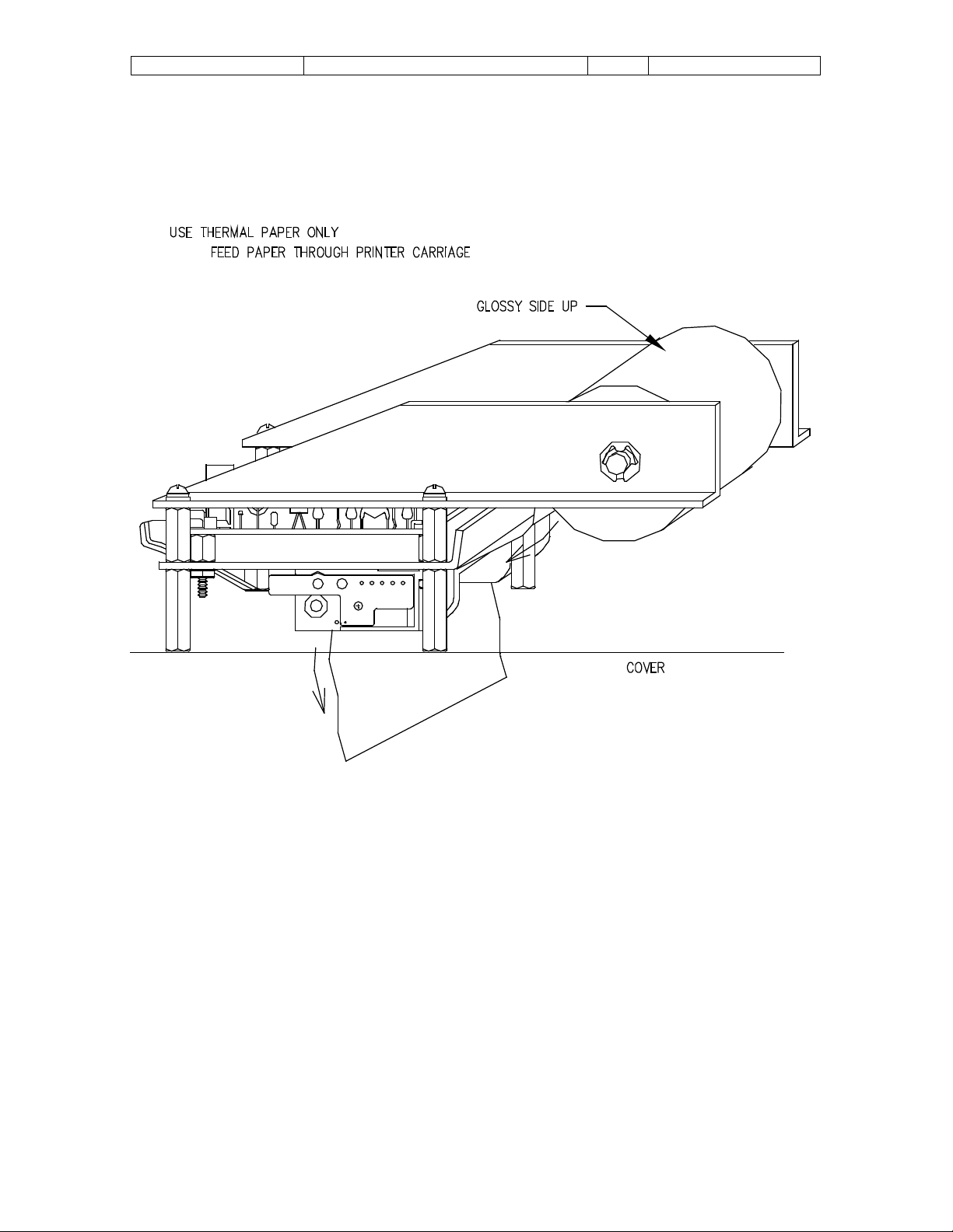
A. Printer paper installed backwards (see drawing)
B. W rong pri nt er p ap er (Use thermal impac t printer paper onl y!)
C. Temperature too cold for printer paper
D. Defective pri nter
Page 9

Sponsler, Inc.
T350N-P Truck Totalizer/Printer
pg. 9
Doc# MN-T350N-P
TROUBLE SHOOTING
(INTERNAL RAM TEST (Dipswitch pos itio n #9)
The self-test mode allows the totalizer’s microprocessor to per form internal tests
on the built-in RAM and ROM.
problem is suspected with the totalizer.
The self test feature should be used only when a
To start the self-test, first set the pre-
scale selector switch (S4) to position #9 (self test).
To fully test itself, the on-board computer must perform 257 different tests. As
each test is completed, A & B LED’s on the RLC113 PCB will flash. In order to
perform the complete test the leds must flash 257 times. Upon completion of the
257 test the LCD display will print ‘Eprom & RAM OK!’. Any other message
indicates an error. If no message app ears on th e LCD di splay, it is poss i ble that
the dis pl ay b i as c ont r ol is not ad jus t ed properly. To make the display and
background darker, adjust the display bias control fully counter-clockwise.
Adjusting this control clockwise will make the display and background lighter.
As long as the pre-scale selector s wit c h (S4) is in position #9, the microprocessor
will continue to test itself. Leaving the switc h in position #9 is a good way to
isolate any transitory problems.
NOTE: Be sure to set the pre-scale selector switch back to the correct position
for pr op er operation.
Page 10

Sponsler, Inc.
T350N-P Truck Totalizer/Printer
pg. 10
Doc# MN-T350N-P
RLC113 P CB ILLUSTRATION
Page 11
Sponsler, Inc.
T350N-P Truck Totalizer/Printer
pg. 11
Doc# MN-T350N-P
T350N—P PAPER INSTALLATION
Page 12

Sponsler, Inc.
T350N-P Truck Totalizer/Printer
pg. 12
Doc# MN-T350N-P
T350N-P 8X10X4
Page 13

Sponsler, Inc.
T350N-P Truck Totalizer/Printer
pg. 13
Doc# MN-T350N-P
TEMPERATURE COMPENSATION (RLC131 option)
As product flows through the pipeline, a turbine located in the product spins and
electrical pulses are generated and sent to the totalizer. The number and
frequency of these pulses corresponds to the amount of product flow and the
flow rate.
As the product I the pipeli n e heats or cools , the dens it y and vol ume of the
product changes. When the volume of product changes, the turbine spins faster
or slower since the turbi n e fl ow m et er is a vol u m etr ic m eas uring d evice, even
though the AMOUNT (measured by weight) of product is not changed.
Temp er at ur e c om pens ation operates by r ead i ng th e t emp eratur e of t he produc t
and add in g or subtrac t i ng pu lses bas ed on t h e tem p erature and hence the
density of the product.
As long as the product flowing past the temperature sensor is within range of the
product, the temperature compensation module will automatically correct for the
density of the product. If the product is not within the correct temperature range,
or an elec tr ical problem exis ts wit h the temper at ur e probe, the comp e nsation
modu l e will n ot c omp ensat e for th e pr oduct and wil l si mp l y op er at e o n 1 1: 1 b asis
without compensation.
Whenever the temperature goes out of range for the selected product, the
ALAR M LED w ill illu m inate. If the relay opti on is inst alled, an d ext ernal r el ay will
be ener gi z ed w h enever th e alarm cond ition exis ts . If jum p er JU 2 is i ns talled on
the RLC131 compensation board the totalizer will stop accepting incoming
pulses. Any pulses in storage will be outputted since these pulses were
accepted wh il e th e unit was not in al ar m conditi on.
An addit ional f eature exis ts if the op erator wis h es to turn off tem p er at ure
compensation even if the RLC131 Compensation Module is installed. To turn off
temperature compensation install JU4 on the RLC131 module. When installed,
no temp er at ur e c om pens ati on exists and in pl ac e of th e pr oduc t temp eratur e on
line 1 of the LCD is the message ‘NO TC’.
Page 14

Sponsler, Inc.
T350N-P Truck Totalizer/Printer
pg. 14
Doc# MN-T350N-P
The following table summarized the various positions of the product selector
switch (RLC131 PC board) and the corresponding product.
Position Product Low Temp Ref Temp Hi Temp.
0 OXYGEN -199.977 -183.111 -140.583
1 NITROGEN -210.370 -195.930 -155.309
2 ARGON -188.953 -186.046 -140.583
3 CO2 -40.050 -25.166 -6.318
4 N20 -51.087 -34.679 15.384
5 CH4 -17.171 15.611 37.934
6 MAPP -18.017 15.146 51.924
7 LPG -40.142 15.318 50.877
Page 15

Sponsler, Inc.
T350N-P Truck Totalizer/Printer
pg. 15
Doc# MN-T350N-P
PROGRAMMING TIME AND USER CONFIGURABLE MESSAGES
Progr am m in g of t h e cl oc k or user defin able mes sages is accompl is h ed us in g t h e
external 4X4 programming keyboard. This keyboard must be plugged into the
unit before programming can begin.
The Ticket Printing Totalizer contains a built-in real time clock. The time and
date inform ati on su pplied by this cl oc k is us ed to time and d at e stamp eac h tic k et
during printing. It is important that the time and date information is correct for
proper record keeping. Setting the clock begins by pressing the SET CLOCK
key. If the clock has never been set, or the battery has just been changed, the
time an d d ate inform at i on dis p l ay ed by the cl ock on lin e 1 wi ll b e garbag e.
Pressing the CLEAR key will initialize the clock to the default time of 12:00A 01JAN-80. Clock information can be changed by moving the cursor using the ( ) ( )
keys, to the location containing the data to be changed. Once at the proper
location, press the ( ) key to increment the data. For example, if the cursor is
under the mont h of MAR and th e ( ) ke y is press ed, th e m onth with c h ang e to
APR. Pressing the (v) key will decrement the data at the cursor location.
When the time and date information is set correctly, press the ENTER key to
stor e the n ew time and r etur n to the setup menu.
The tic k et pr in ting total iz er h as bu ilt in mem or y that al l ows th e op er at or to st ore a
custom message. The user definable message will be printed as the top 2 lines
(by 16 characters per line) on each ticket. Each message line can be up to 16
characters long. Any information such as company name, phone number, etc.
can be stored. Setting the message begins by pressing the SET MSSGE key. If
the message is being set for the first time, or the battery has just been changed,
the message information disp l ayed on th e LCD wi ll be g ar b ag e. Pressing the
CLEAR key will clear both message lines. Message information can be changed
by moving the cursor using the ( ) for proper location, press the ( ) or (v) keys to
change the data. Follo wing is a list containing the order in which data is
incremented/decremented:
!”#$%¢’()*+,-./ 0123456789:; = ? @ABCDEFGHIJKLMNOPQRSTUVXYZ (cont)
[/] _ abcdefghijklmnopqrstuvwxyz
If the first character of a message line is set to a ‘)’, then the entire message line
will not be printed. In this way it is pos s ible to skip messa ge lines rather than
havi ng bl an k li n es pr i nt ed at th e top of each tic k et.
Once the message information is set correctly, press the ENTER key to store the
mess ages and retu r n t o th e s etu p m enu.
Page 16

Sponsler, Inc.
T350N-P Truck Totalizer/Printer
pg. 16
Doc# MN-T350N-P
TICKET PR IN TING TOTALIZER WI TH TICKET STORAGE (350S)
ENTERING ACCOUNTS
W hen the 35 05 i s firs t turned on, th e operator is pr om pted to enter an account
numb er. This account nu mb er m ay c ons is t of 0 thr ou gh 16 digits . T o ent er an
account number, type in the appropriate number using the built-in keypad.
Pressing ‘ ‘ will erase the last digit typed. Pressing CLEAR will clear the entire
message line.
Onc e an acc ou nt nu m b er had b een entered, t h e op erator mus t pres s the ENTER
key to b egi n n or m al op eration of the 3505. The account num b er is u s ed as an
indicator to track deliveries to specific customers. The account number will be
print ed on t h e tic k et, an d is also record ed and used wh en pr i nting tic k et
summ ar i es. If the wr on g account nu m b er h as b een entered, t h e uni t mus t b e
turned of f , th en b ac k on s o an oth er account numb er can b e entered.
While tickets are being printed, the number of available ticket storage locations
will appear on line 1 of the LCD. After the ticket is finished printing, line 1of the
LCD will return to its normal condition. If all ticket storage locations are used up
(Available = 0), the unit will still continue to operate properly, however no new
tickets can be stored. Ticket storage memory will be regained when tickets are
erased after a ticket summary is printed.
Page 17

Sponsler, Inc.
T350N-P Truck Totalizer/Printer
pg. 17
Doc# MN-T350N-P
1-clock 3-Summary
2-Mssge 4-Baud
350S ADDENDUM
PARAMETER SETUP
The parameter setup function of the 3505 allow s the operator to set i nforma ti on
necessary for proper operation of the unit. Although setup can be performed anytime by
anyon e, i t i s recommend ed that only those persons fami liar wi th sy stem operati on use
the setup function.
To enter the setup function, the operator must hold down the RESET key on the keypad
when power to the unit is being turned on.
Whenever the set up mode i s entered, the foll owi ng message will be di splayed.
When this mes sage is d isp layed, th e 350 5 is in t he setup mode. The setup mode allows
setting the f ollow ing parameters:
1) Setting the real time clock
2) Setting a custom 2 line message
3) Printin g a transaction summary
4) Setti ng the serial interface baud rate
1) Setti ng the clock begins by pressing the ‘1’ key. Pressing the CLEAR key will
initialize the cloc k to the default time of 12:00A 01-JAN-80. Clock information can be
changed by moving the cursor using the ( ) or ( )keys to the location containin g the
data to be chan ged . Once at the proper loc ation, pr ess t he (u p ar row) key (#8
button) to increment the data. For example, if the cursor is under the month of MAR
and the (up arrow) key is pressed, the month will change to AP R. Pr essi ng the
(d own arr ow) key (#2) will decrement th e data at the cursor l ocati on.
When the time informat ion is set correctly, press the ENTER k ey to s tore the new ti me
and return to the setup menu.
2) Setti ngs the message begins by pressing the ‘2’ key. Pr essing the CLEAR key will
clear both m essage lin es. Messag e information can be chan ged b y movin g the
cursor using the ( ) or ( ) keys to the location containing the data to be changed.
On ce at the proper loc ation, pr ess the (up arr ow) or (down arr ow) keys to c hange t he
data. Follow ing is a list c ontaining the order I which data is incremented/
decremented:
!”#$%¢’()*+,-./ 0123456789:; = ? @ABCDEFGHIJKLMNOPQRSTUVXYZ (cont)
[/] _ abcdefghijklmnopqrstuvwxyz
If the fir st c har acter of a message line is s et to a ‘) ’, t hat entire mes sage line w ill not be
printed. In this way it is possible to skip m essage lines rather than having blank lines
pr inted at the top of each ti cket. O nce t he message i nformation is set c orre ctly, press
the ENTER key to stor e the mes sages an d return to the setup menu.
Page 18

Sponsler, Inc.
T350N-P Truck Totalizer/Printer
pg. 18
Doc# MN-T350N-P
350S ADDENDUM
3) To print a summary of all stored tic kets , press the ‘3’ key. A ticket summary of all
stored tic kets will be pri nted. I f some t i ckets h ave been lost due to battery power
pr obl ems or i f the unit had be en put i nto external m emory t est ( wh i ch destroys data
stored in the ticket storage memory), then the SOM E TICKETS L OST! mes sag e wi ll
be printed at the top of the summary. Summary starts by listing the date at which the
ticket had been printed, then all tickets p rin ted on that date are l isted alon g wit h the
ti me the units deliver ed. The n umber of tickets that c an still be stored in memor y is
printed at the end of the summary.
Followi ng is an example of a t icket summar y .
***************************
Transaction Summary
12:34A 12-OCT-87
********12-JUL-87*******
12:22P 1233 1222
02:20P 3456 6546
03:59P 421 213
******* 13-JUL-87 *******
01:22:P 45654 6788
Available = 116
Af ter the ti cket summary is printed, th e operat or i s asked i f th e stored ti cket in f ormation
is to be kept or erased. The operator enters ‘1’ t o erase st ored ti cket informati on, or ‘0 ’
to keep stored tic ket information. If t he ti cket informati on is to be erased, the oper ator is
pr ompted to en ter a password. The password prevents unauthorized persons from
er asin g tic kets . To eras e ti ckets the corr ect pass wor d of 132 4 must be entered.
4) Changing the band rate begins by pressing the ‘4’ key. The current baud rate setting
will be displayed on the LCD. Pressing t h e ( ) or ( ) keys will press the ENTER key.
The valid baud rate settings are: 110, 150, 300, 600, 1200, 2400, 4800, 9600.
SER IAL INT E R FACE C O MMANDS
When the 350S in t he setup mode, t he un it will res pond to s everal com mands
transmitted via t he serial interface. These comman ds al low the unit to be e xter nally
pr ogrammed v ia an ext ernal computer or modem. A special feature available with 350S
allows all s tored tickets to b e transmi tted to an external computer, t hereby facilit ati ng
automatic billing an d record ing sys tems. All seri al i nterface c onforms to standard AS CII ,
8 data bits, 1 stop bit, no parity. The communication baud rate is programmable by the
operator using setup function #4.
Page 19

Sponsler, Inc.
T350N-P Truck Totalizer/Printer
pg. 19
Doc# MN-T350N-P
350S ADDENDUM
Followi ng is a list of com mands avai lable and their corresponding funct i ons:
(C) W henever a CHR$(6 7) i s received, t he 35 0S enters t he set clock mode. This mode
op erates exactly the same as the setting mess age s vi a the keypad, except com mands
ar e received f rom the serial port.
The followi ng commands are used when setti ng b oth t he c loc k and mess ages.
(sp) CHR$(32) move cursor 1 location to the right.
( H) CHR$( 8) mov e cursor 1 locat ion to the left .
( ) CHR$(6 2) increm ent data at cursor l ocati on.
( ) CHR$(6 0) d ecrement data at c ursor locat ion.
(C)CHR$( 67) set data to space at cursor locat ion (m essage on ly)
(R)CHR$( 82) reset cl ock/ mes sag e to default setting
(N)CHR$(78) toggle introductory message. *
( Z)CHR$(26) store clock/message as it appears and return to setup menu
*The introductory message is printed when power is first turned on.
The followi ng commands are available only on the 35 0S with ticket st orag e functi on.
These commands will only functi on when the unit is in the setup mode.
(T) Whenever a CHR$(84) is rec eived, t he 350S will b egin a st ored ti cket dump in
exactly the s ame f ormat as printed on the built-in printer. The oper ator is s ti ll promoted
on the L CD i f it i s desirab le to erase st ored ti ckets.
(D) W henever a CHR$(6 8) i s received, t he 35 0S begi ns a HEX d ump of all data stored
in the 2048 b yte t i cket memory. If it is desir able to erase stored tickets af ter the
memor y dump, th e let ter (e) CHR$(10 1) shou ld be transmitted while the memory dump
is taking place. If ( e) is received by the 350S, all s tored tic kets wi ll be erased. NOTE:
The operator is n ot prom pted to erase tic kets when using this function.
Page 20

Sponsler, Inc.
T350N-P Truck Totalizer/Printer
pg. 20
Doc# MN-T350N-P
SCI---- T350N-P-01 Dime ns ion al
Page 21

Sponsler, Inc.
T350N-P Truck Totalizer/Printer
pg. 21
Doc# MN-T350N-P
SCI—T350N-P-K-0 1 Di me nsional
Page 22

Sponsler, Inc.
T350N-P Truck Totalizer/Printer
pg. 22
Doc# MN-T350N-P
Page 23

Page 24

© 20 09
Pub. No. MN-T350N-P
(9/2009)
 Loading...