

Page 1

INSTALLATION & OPERATION
MANUAL
SP718-V REV. A
Modulated Carrier Amplifier
0-5V/0-10V Transmitter
DOC#: MN-718V-A.doc
Page 2

Sponsler, Inc.
SP718-V Modulated Carrier Amplifier
pg
2
DOC#: MN-718V-A
Temperature:
Operating 0 – 70oC
110VAC 60Hz or 12 – 16.5VDC 50mA MAX
Signal Input:
Frequency 0 – 3500 Hz w/ 50KHz carrier (requires P/U Coil 1 – 1.3 mh)
Switch Selectable Output Range
Weight 1. 7 lbs.
SPECIFICATIONS
Storage –20 – 85oC
Input Voltage:
Observe Polarity
Consult factory for other I nput Voltages
Analog Output:
Features:
Enclosure:
0V @ 0Hz, 5 or 10 V @ desired Full Scale Frequency
Full Scale Range 60 Hz – 3500 Hz Selectable
Consult factory for other Rang es
Response Time 95% of change in 1 second
Linearity .3% F/S
Tempco <2% of Reading over entire Temperature Range
Maximum Load Resistance 1000 ohms
Mounts directly on flowmeter
FM Approved, CSA Certified
Class I Groups B, C, D
Class II Groups E, F, G
The SP718-V Modulated Carrier Amplifier and Analog Transmit t er is a meter mounted device designed to
combine the advantages of the Modulated Carrier principle with the convenience of an Analog O utput in a
single PCB Assembly. The SP718-V linearly converts the detected carrier frequency shift rate to an
equivalent voltage output level, 0-5V/0-10V that is switch selectable. When incorporat ed with a turbine
flowmeter, a voltage representation pr opor tional to flow is obtainable.
The SP718-V produces a carrier frequency in conjunction with a RF pick-up coil, detects the shif t in the
carrier frequency (Modulation) that occur s with the passage of magnetic mat er ial and linearly generat es a
voltage output that is proportional to the rate of Modulation.
A full-scale freq uency range of 60-3500Hz is jumper selectable. The Span adj ustment establishes the
frequency point at which the Full Scale Output is achieved.
The Modulated Carrier principle introduces no drag on the passing magnetic device therefore; when utilized
with a turbine flowmeter extension of the flowmeter’s nom inal linear range at the low end of the flow
spectrum is realized. This parameter is particularly useful when measuring a low mass gas and the
operating flowrate is at the f lowmeter ’s low end.
Page 3

Sponsler, Inc.
SP718-V Modulated Carrier Amplifier
pg
3
DOC#: MN-718V-A
NOTE:
All test equipment power cords should be equipped with 2-prong ‘cheat er ’ plug s.
A)
Connect Flowmeter with RF Pick-up Coil to J1-1,2
Connect Power Supply Positive (HOT) & Negative (NEU) Leads to J1-6,5
Respectively
C)
Connect O’Scope Positive & Negative Leads to J1-1,2 Respectively
D)
Connect DMM Positive & Negative Leads to J1-3,4 Respectively, Set Function to
Volts DC
E)
Install Jumper @ JU4, Set S1 for desired Output Voltage Level
F)
G)
Turn Power Supply ‘ON’, LED D1 Illuminates & O’Scope displays a 50KHz +/- 5KHz
Carrier Sinewave
H)
Observe Carrier Amplitude of 6Vp-p
I)
Adjust ‘ZERO’ (R25) for a DMM Indication of .000V
J)
Disconnect O’Scope
K)
Connect Frequency Generator Positive and Negative Leads to J1-1, 2 Respectively;
Point
L)
Adjust ‘SPAN’ (R23) for a DMM Indication of 5.00V or 10.00V
Reduce Signal Amplitude of Frequency Generator to Zero, Adjust ‘ZERO’ (R25) for
DMM Indication of .000V if necessary
N)
Increase Signal Amplitude of Frequency Gener ator to 5Vp-p; Adjust ‘SPAN’ (R23) for
DMM Indication of 5.00V or 10.00V if necessary
O)
Adjust Frequency of Frequency Gener ator to 0, 25, 50, 75, & 100% of Full Scale
To check for Linearity at any Freq uency Point, incor por at e t he following formula -
(F/F Max X Full Scale Output) = Volts
Example: Assume Maximum Frequency Point = 2KHz (5 or 10V Point)
.375 X 10 = 3.75V DMM Should Indicate – 3.75V @ 750Hz
BENCH TEST CALIBRATION PROCEDURE
Required Equipment: Power Supply 12-16.5VDC or 110VAC
Digital Multimeter ( DMM)
Frequency Generator
Frequency Counter
Oscilloscope
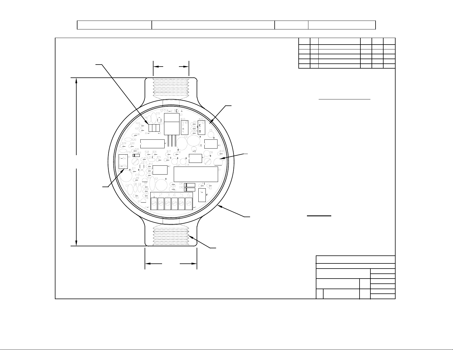
Refer to Figure
Test Procedure:
B)
Install Jumper @ JU1-3 for desired Full Scale Freq uency Range
Set Function to Squarewave Amplitude to 5Vp-p & Frequency to desired Full Scale
M)
Frequency of Step K
Check for Linearity at 750Hz. 10V Full Scale Output
750/2000 = .375
Page 4
Sponsler, Inc.
SP718-V Modulated Carrier Amplifier
pg
4
DOC#: MN-718V-A
5.60
1.40
3/4-14 FNPT
2.40 DP.
3.75 DIA.
5-5-97
TN
EM SP718-V-A
SP718-V REV. A AMPLIFIER
\ELECT\SP718V.DWG
NONE
DRAWING NUMBER
MATERIAL
SPONSLER, INC.
SCALE
DRAWN BY
DATE
APPR. BY
DATE
REVIEWED BY
DATE
DESCRIPTION
REV. #
FILE NAME
COD
REV
CKDRAUTH
REVISION RECORD
DATE
SIGNAL IN +
SIGNAL IN –
ANALOG OUT +
ANALOG OUT –
110 VAC NEU (DC-)
110 VAC HOT (DC+)
1
2
3
4
5
6
TERMINAL LOCATION
NOTE: DIMIENSIO NS ARE IN INCHES
.90
3.00 DIA.
POWER INDICATOR
F/S FREQUENCY RANGE SELECT
JU1 60-245 Hz
JU2 220-925 Hz
JU3 845-3800 Hz
ANALOG
OUTPUT
SELECT
NOTE:
Condulet enclosure not
available for 120 volts,
consult factory
©2009
Pub. No. MN-718V-A
(09/09)
 Loading...