

Page 1
Page 2

Table of Contents
Introduction
Software License Agreement............................. 3
DMS i1000 i1000 Overview ............................... 4
DMS i1000 i1000 System Components............. 5
Specications .................................................... 6
DMS i1000 Lap Pad .......................................... 7
Navigating DMS i1000 Lap Pad ........................ 8
Field Edit and List Box Windows ....................... 9
DMS i1000Menu
System Utilities ................................................ 12
Data Application List ........................................ 16
Database Management ................................... 17
LCR Host
Main Menu ....................................................... 20
Setup Network ................................................. 21
Setup Network Port ......................................... 24
System Parameters ......................................... 26
Congure LCR ................................................. 28
General Setup ................................................. 29
System Calibration .......................................... 32
Product Calibration .......................................... 37
Single-Point Calibration ................................... 44
Multi-Point Calibration ..................................... 45
Diagnostics ...................................................... 48
Security............................................................ 49
Factory Setup .................................................. 50
Save Conguration .......................................... 51
Load Conguration .......................................... 52
LCR Host Delivery
Preset and Delivery ......................................... 54
Device Not Found ............................................ 59
Machine Status ................................................ 60
Printer Status ................................................... 61
Delivery Status ................................................ 62
Delivery Code .................................................. 63
LCP File Server
Setup LCP File Server ..................................... 66
File Management ............................................. 69
Software Menu Maps
Software Menus - DMS i1000Menu................. 72
Software Menus - LCRHost ............................. 73
Software Menus - LCP File Server .................. 82
Publication Updates and Translations
The most current English versions of all Liquid Controls publications are available on our web site, www.
lcmeter.com. It is the responsibility of the local distributor to provide the most current version of LC
manuals, instructions, and specication sheets in the required language of the country, or the language
of the end user to which the products are shipping. If there are questions about the language of any LC
manuals, instructions, or specication sheets, please contact your local distributor.
! WARNING
• Before using this product, read and understand the instructions.
• Save these instructions for future reference.
• All work must be performed by qualied personnel trained in the proper application, installation, and maintenance of
equipment and/or systems in accordance with all applicable codes and ordinances.
• Failure to follow the instructions set forth in this publication could result in property damage, personal injury, or death from
re and/or explosion, or other hazards that may be associated with this type of equipment.
2
Page 3

Software License Agreement
Read this license carefully. You agree that by using the eldized software package, you have agreed to the software
license terms and conditions. This agreement constitutes complete and entire agreement between you and Liquid
Controls with respect to this product.
1. Liquid Controls hereby grants to Licensee a nonexclusive
license to use DMS i1000 Menu, LCP File Server,
FleetConnect Ofce, and LCR Host Software (hereinafter
referred to as “Licensed Software”)
2. Under the License granted herein, Licensee may use the
eldized machine readable (executable code) copy of the
Software, including any subsequent updates which may
be provided. Licensee shall not, without Liquid Controls’
prior written consent, (a) rent, lease, lend, sublease or
otherwise transfer the materials hereunder; (b) remove or
obscure proprietary or copyright notices which may be set
forth on the Licensed Software; or (c) alter, decompile, or
disassemble the program.
3. One (1) copy of the Licensed Software, including any
software distributed on disks may be made for backup
purposes only. No other copies may be made or used
without the written consent of Liquid Controls.
4. Title. No title to ownership of any Licensed Software is
transferred to the Licensee.
5. Upgrades. License upgrades may become available for
the Licensed Software. Any cost associated with such
upgrades will solely be determined by Liquid Controls.
6. Warranty. Liquid Controls makes and licensee receives
no warranty express or implied and there are expressly
excluded all warranties of merchantability and tness for
a particular purpose.
8. Termination. Liquid Controls may terminate this software
license granted hereunder and require return of the
Licensed Software if Licensee fails to comply with these
license terms and conditions.
9. Licensee acknowledges that it has read this agreement,
understands it, and agrees to be bound by its terms, and
further agrees that this is the complete and exclusive
statement of the agreement between Liquid Controls
and Licensee, which supersedes and merges all prior
proposals, understandings, and all other agreements, oral
or written, between the parties relating to this agreement.
This agreement may not be modied or altered except by
written instrument duly executed by both parties.
10. This Agreement and performance hereunder shall be
construed and interpreted under the laws of the State of
Illinois.
11. If any provision of this agreement is invalid under any
applicable statute or rule of law, it is to that extent to be
deemed omitted.
12. Licensee may not assign or sublicense, without the
prior written consent of Liquid Controls, its rights, duties,
or obligations under this Agreement to any person or entity
in whole or in part.
13. The waiver or failure of Liquid Controls to exercise in
any respect any right provided herein shall not be deemed
a waiver of any further right hereunder.
7. Limitation of Liability. Licensee shall have the sole
responsibility for adequate protection and backup of its
data in connection with the Licensed Software. In no event
shall Liquid Controls be liable for (a) special, indirect or
consequential damages; (b) any damages whatsoever
resulting from loss of use, data, or profits, product,
inaccurate input or work delays, or any direct property
damage arising out of or in connection with this agreement
or the use or performance of the Licensed Software.
3
Page 4
DMS i1000 i1000 Overview
LectroCount Data Management System
DMS i1000Menu
LCRHost DMS i1000 Delivery LCP File Server
DMS i1000 Ofce Program
LectroCount DMS i1000 is a “Data Management System”
comprised of a DMS i1000 Module, DMS i1000 Lap
Pad, and function specic software applications. The
DMS i1000 Module is a hardware component which the
LectroCount registers, printer, DMS i1000 Lap Pad, and
power supply are connected.
The DMS i1000 software components consist of a system
operating software, DMS i1000Menu, LCRHost, DMS
i1000 Delivery, and LCP File Server. The DMS i1000
software applications are function specic.
DMS i1000Menu: An application which allows an operator
ability to switch between LCRHost, DMS i1000
Delivery, and LCP File Server. DMS i1000Menu also
provides ability to transfer and receive information
from a DMS i1000 Ofce program.
LCRHost: An application providing an operator ability to
setup LCR Networks, calibrate LectroCount LCR and
LCR-II electronic registers, and make deliveries.
DMS i1000 Delivery: An application providing an operator
ability to select customers from a customized list,
make deliveries, record/track deliveries, review
shift information, and transmit completed delivery
information to a DMS i1000 Ofce Program using a
USB ash memory.
DMS i1000 Ofce Program: This program runs on an
ofce computer. It is used to congure the DMS i1000
Delivery application an operator will use while making
deliveries, as well as customization of a delivery ticket.
It is also responsible for converting data les between
ofce software formats and the DMS i1000 Module.
DMS i1000 Delivery component of the LectroCount
DMS i1000 Data Management System is an application
designed to record and maintain delivery information.
DMS i1000 Delivery is not covered in this publication.
Instead, this publication covers the DMS i1000Menu,
LCRHost, and LCP File Server applications. These
applications are accessed via the DMS i1000 Lap Pad.
The DMS i1000 Lap Pad is a terminal interface device
with a display having up to eight lines of information. It
attaches directly to the DMS i1000 Module.
DMS i1000Menu instruction (page 11).
LCRHost instruction (page 18).
LCF File Server instruction (page 65).
DMS i1000 Delivery instructions are covered in the
LectroCount DMS i1000 Operator’s Manual: 500344.
Other LectroCount DMS i1000 publications include:
LCP File Server: An application providing an operator
ability to access files of the DMS i1000 Module
from other computer systems in a manner similar to
Windows® Explorer. Files on other devices running
LCP File Server are also accessible.
Windows® is a registered trademark of Microsoft Corporation.
• LectroCount DMS i1000 Installation Manual: 500343
• Quick Reference Card: 500345.
• Ofce Installation & Operation Manual: 500346.
NOTE: LC software is copyright protected and may not be
duplicated under any circumstances without authorization
from Liquid Controls.
4
Page 5
DMS i1000 i1000 System Components
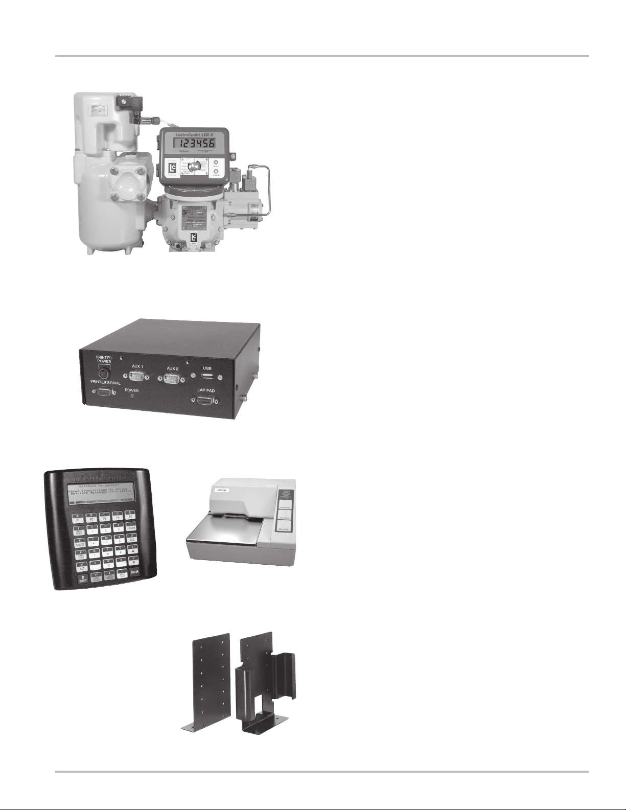
Typical vehicle delivery system components:
Metering System
Metering system is typically mounted to the back or
side of the delivery vehicle and measures the ow of
product being delivered. Components of this system
can include the meter, electronic register, strainer, air
eliminator, and control valve.
DMS i1000 Module
DMS i1000 Module provides connections for the
printer, DMS i1000 Lap Pad, electronic registers,
and a USB ash memory (optional). Powered from
the vehicle’s accessory panel and often mounted on
support brackets in the cab of the vehicle.
M-10 Meter with LectroCount LCR-II Electronic
Register, Optical Air Eliminator, Hi Capacity Strainer,
and E-7 Valve.
DMS i1000 Module
DMS i1000 Lap Pad
DMS i1000 Lap Pad is the user interface device which
allows initial set up and calibration of the system and
an interface for daily deliveries.
Printer
Printer is used to print out a record of the delivery. This
ticket is typically a multi-layer ticket providing a copy
with the customer and a copy retained for physical
record of the delivery.
DMS i1000 Lap Pad
Epson Slip Printer
Support Brackets
5
Page 6

Specications
DMS i1000 Lap PadDMS i1000 Module
Enclosure
Dimensions
6.875” W x 2.625” H x 7.25” L
Material
Powder painted steel
Operating Voltage
+9 to 30 VDC, less than 3A
Temperature Rating
-13° to 158°F (-25° to 70°C)
Microprocessor
133 MHz, 486
Memory (Primary Hard Drive)
Internal ash memory
Housing
Lightweight, high impact, molded plastic.
Housing Rating
NEMA 3, IP54
Display
LCD, dot matrix, 240 x 64 pixels, backlit.
5.2” wide, 1.55” tall; 8 rows, 30 characters per row.
Keyboard
6 row, 5 column membrane with tactile metal dome
switch contacts and silicon rubber overlay.
Supply Current
150 mA maximum
Temperature
-13°F to 158°F (-25° to 70ºC)
Vibration
2 g between 10-150 sinusoidal sweep cycle. 20
sweep cycles per axis.
Electrostatic Discharge
IEC801-2
8 kV for air discharges
6 kV for contact discharges
Electromagnetic Susceptibility
IEC 801-3
3 V/m 26-500 MHz
1 V/m 500-1000 MHz
Interface
RS-232 at 115,200 baud rate
6
Page 7
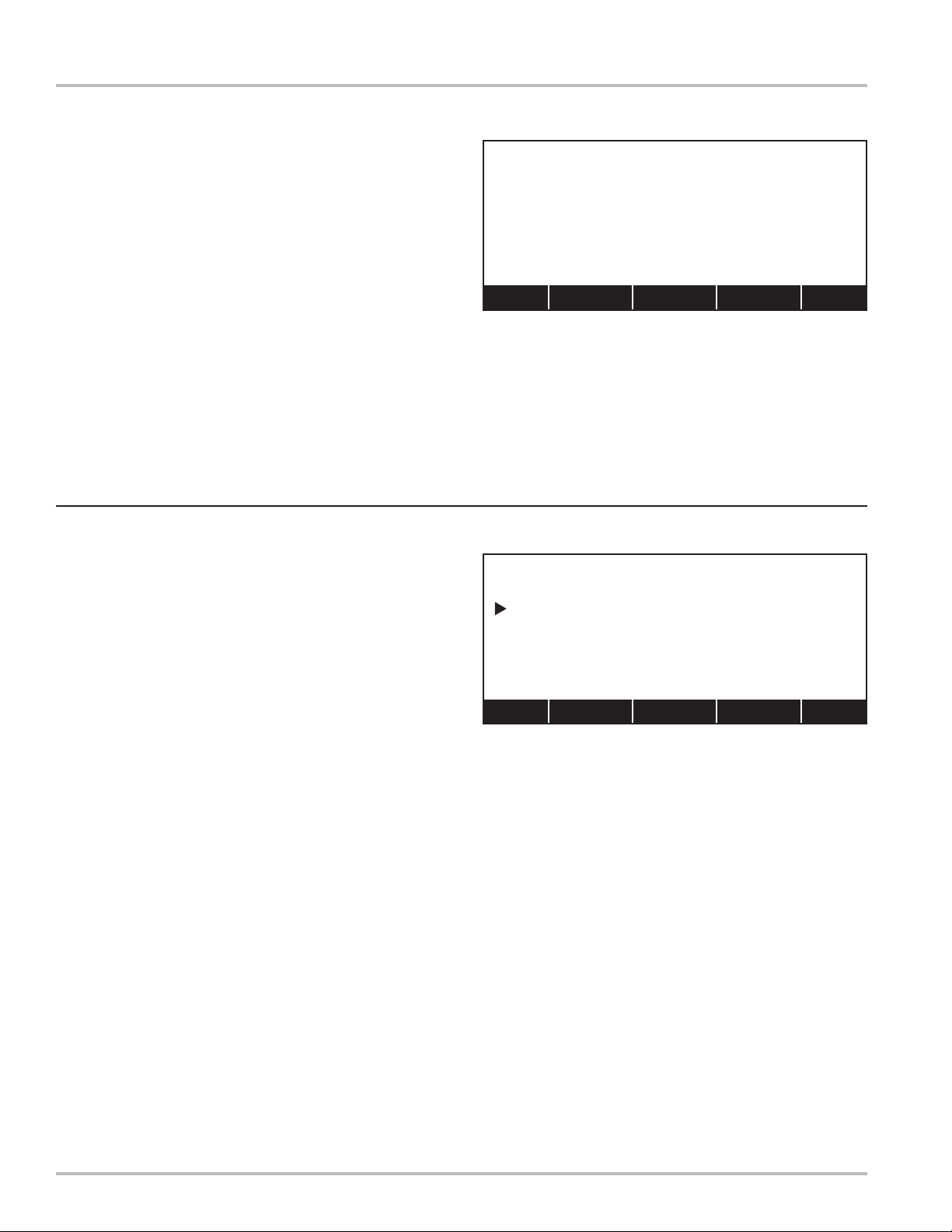
DMS i1000 Lap Pad Setup
DMS i1000 Lap Pad Setup
DMS i1000 Lap Pad Setup v.1.00
(c) Liquid Controls LLC 2005
Adjust Contrast with and
Backlight:
Blink Cursor?
Auto Repeat:
CR and LF as Graphic?
Press ESC to exit.
DMS i1000 Lap Pad Setup Screen
On
Yes
Off
Yes
The DMS i1000 i1000 Lap Pad is the user interface
device for the DMS i1000 i1000. In the DMS i1000 i1000
Lap Pad Setup screen, you can change the settings for
the lap pad’s operation and display. While this screen is
loaded, the DMS i1000 i1000 Lap Pad is off line with the
DMS i1000 i1000.
To access the DMS i1000 i1000 Lap Pad Setup:
Press and hold the ALT and ENTER keys
simultaneously.
In the setup screen, the active eld is displayed in reverse
video. For example, in the example to the left, Adjust
Contrast is the active option. Pressing ENTER drops the
active eld to the next item. From the bottom option, the
active eld simply wraps back to the top option.
Adjust Contrast with and
Alters the DMS i1000 i1000 Lap Pad display for optimal
viewing. The up arrow increases the contrast; the down
arrow decreases the contrast.
Backlight:
Turns the light behind the display on and off. Use either
arrow key to change the setting.
DMS i1000 i1000 Lap Pad
Blink Cursor?
Switches the cursor display between solid and blinking.
If set to Yes, the blink rate is 250 ms.
Auto Repeat:
Enables or disables auto repeat when a key is held down.
If set to On, the character being held down will start to
repeat after 250 ms and repeat again every 50 ms.
CR and LF as Graphic?
This option is used to turn the CR/LF graphic on or off.
This eld should be set to Yes, when used with a DMS
i1000 i1000 application. If the Lap Pad is being used as
a standard terminal device, for example, processing DOS
command lines, this eld should be set to No.
Exiting the Lap Pad Setup
Press ESC to exit the DMS i1000 i1000 Lap Pad setup
and reestablish communication with the host computer
(DMS i1000 i1000). The values entered will be retained
each time the unit is powered up.
7
Page 8
DMS i1000 Lap Pad Navigation
Navigating the DMS i1000 Lap Pad
The DMS i1000 i1000 Lap Pad has an 8-line, 30
character per line display. Screen layouts vary according
to function. Some screen lines are xed, and some lines
can be modied. Since there are so many unique screens
throughout the suite of DMS i1000 i1000 application
software, the setup and operation manuals for DMS i1000
i1000 application software will layout each screen and
explain screen navigation according to function.
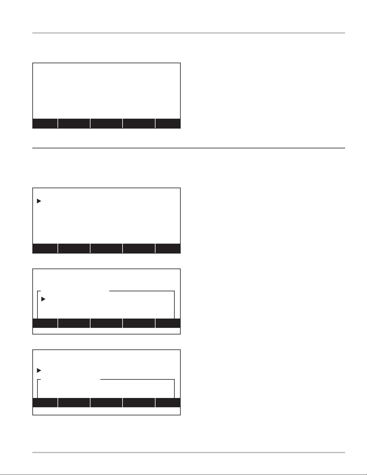
Line 1:
A xed standard eld. The screen title, LOAD TRUCK,
is displayed on the left, and the time, 14:45:07, is
displayed to the right. If there is more than one screen
necessary for a screen title, the screen number will
be displayed between the title and the time (Example
(1/3)).
Lines 2 - 7:
Line 1
Line 2
Line 3
Line 4
Line 5
Line 6
Line 7
Line 8
ACCOUNT INFORMATION
1111113
Albert Constantine
Presets
Miscellaneous Fees
Discounts
Price and Tax
Util
F1 F2 F3 F4 F5
DMS i1000 Lap Pad Display Layout
Back
(2/3)
2
$25.00
0
Fwd
A list of conguration options or DMS i1000 i1000
commands that can be selected using the pointer.
Using the up and down arrows on the DMS i1000
i1000 Lap Pad, the pointer moves up and down along
the left side of the options. The ENTER key selects
the option to the right of the pointer.
Line 8:
The commands assigned to the function keys (F1 -
F5) on the top row of the DMS i1000 i1000 Lap Pad
keyboard. These commands open new screens,
scroll through screens of the same title, and provide
navigation options. This manual will define the
commands available on every screen.
DMS i1000 i1000 Lap Pad
8
Page 9

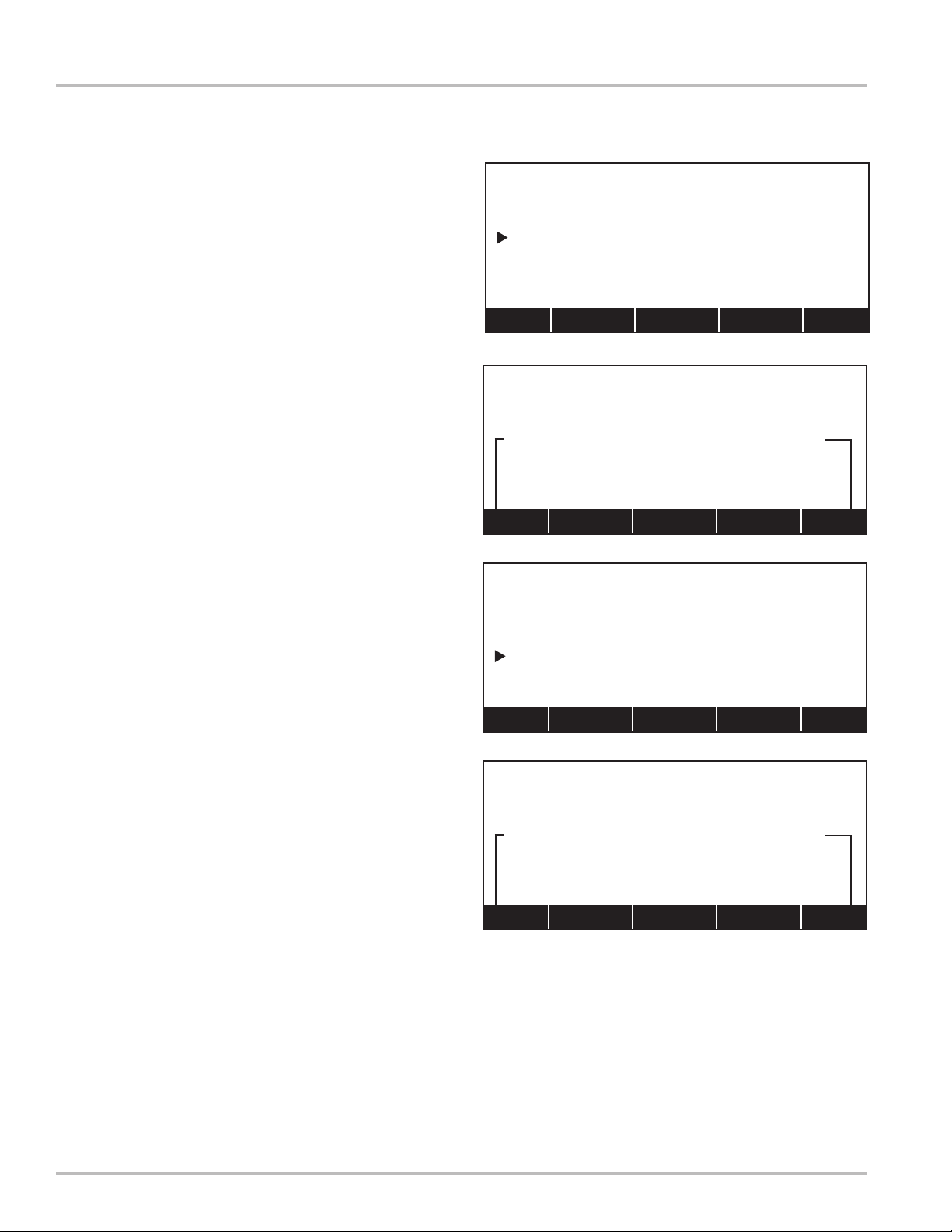
SETUP NETWORK
Network#:
Name:
Network Name
|_ |
Home <-- Ins --> End
F1 F2 F3 F4 F5
Field Edit Window
Home (F1) moves the cursor to the rst position
Ins (F3) toggles between insert mode and over-write mode
F2 and F4 moves the cursor one space to the left or right
End (F5) moves the cursor to the last position in the eld
SHIFT must be held down to type in letters
BACK SPACE erases the character to the left of the cursor
CLEAR erases all characters in a eld edit window
ESC backs out of the window without making changes
ENTER accepts the characters inside the eld edit window
Field Edit and List Box Windows
Field Edit and List Box Windows
There are two editable fields in DMS i1000 i1000
applications: eld edit windows and list box windows.
Field edit windows appear above the function commands
(line 8) as a box in which alpha-numeric characters can
be entered. List box windows also appear above the
function commands (line 8), as a box with a list of options.
Both elds are titled in the upper left corner of the eld
and surrounded by a border. In the example to the upper
right, the eld edit window title is Customer Name. In the
example to the lower right, the list box window is titled
Button ID.
Field Edit Window
Field edit windows allow you to key unique information into
the DMS i1000 i1000. Using the keys of the DMS i1000
i1000 Lap Pad, you can type alpha-numeric characters
into the window, and DMS i1000 i1000 will assign them
to the eld (in the upper right example Customer Name).
While the eld edit window is in the display, the function
keys (F1 - F5) will provide tools to help you maneuver the
cursor inside the window. When you are nished keying
in your information, press the ENTER key to accept and
exit the eld edit window.
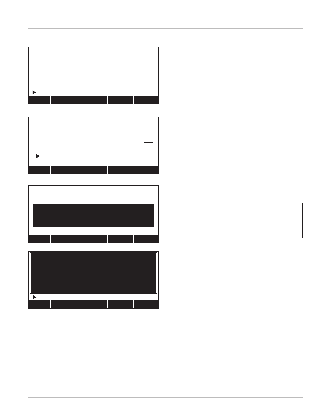
Product Type
Aviation
Distillate
Gasoline
Methanol
LPG
Lube Oil
Home PgUp Find PgDn End
List Box Window
Home (F1) sends the pointer to the rst item in the list
PgUp (F2) and PgDn (F4) scrolls forward or backward through the
list by full screens
Find (F3) opens a eld edit window into which parameters can be
entered for a search
End (F5) jumps to the end of the list
ENTER accepts the option to the right of the pointer
The (F#) function keys are activated only if there are more than
six options
Parameters for each specic eld edit window will be
dened throughout this manual.
List Box Window
List box windows display a searchable list of options for
you to choose from. Use the DMS i1000 i1000 Lap Pad
arrow keys to scroll the (pointer) up and down the list.
Press the ENTER key to select the option to the right of
the pointer. If there are more than six options and the list
will continue to another screen, the function keys (F1 - F5)
will provide navigational tools to accelerate the search.
9
Page 10

10
Page 11

DMSMenu Application
11
Page 12
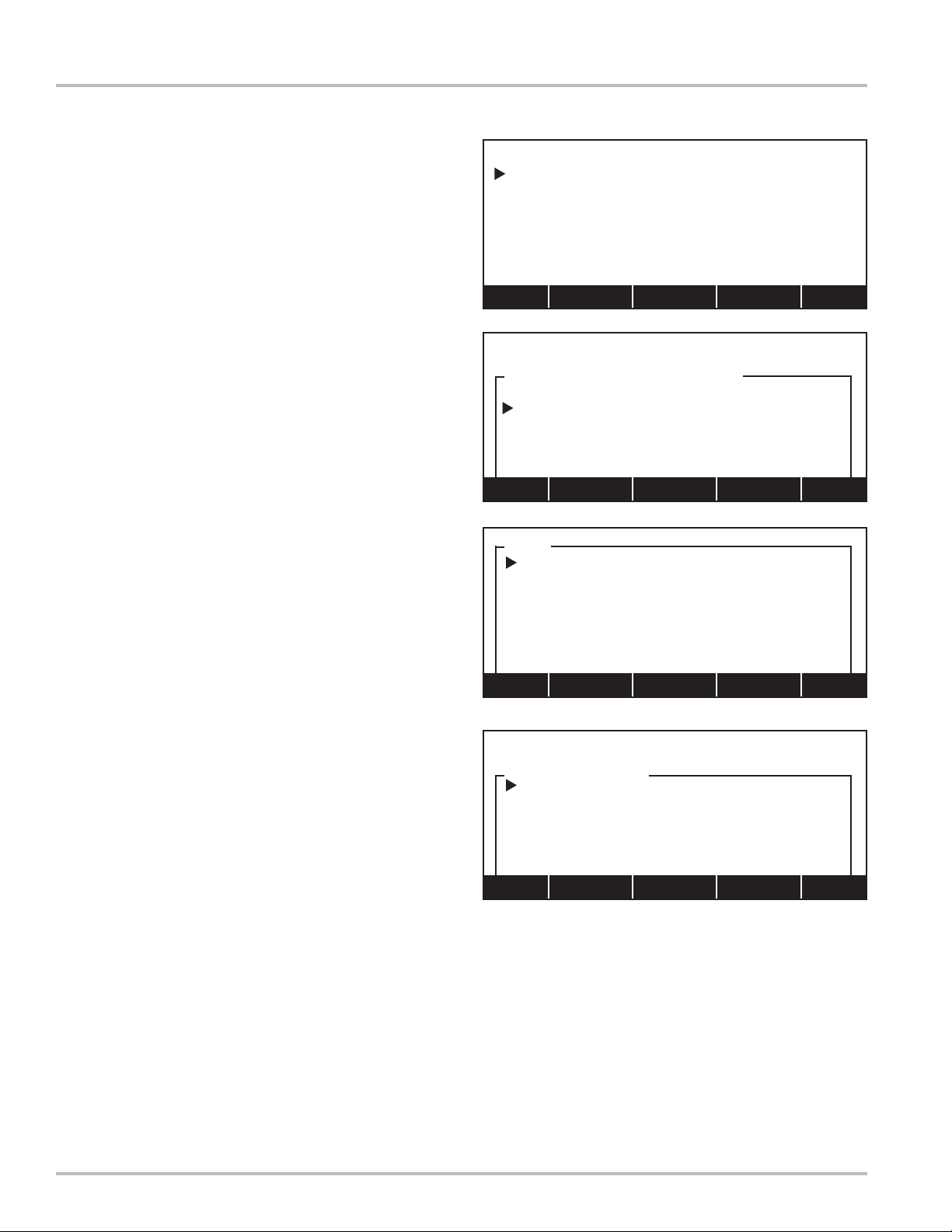
System Utilities
Screen 1: Program Initialization
For newly installed LectroCount DMS i1000 systems,
DMS i1000Menu will launch the rst time the system is
powered up. The display to the right will appear on the
DMS i1000 Lap Pad prompting the operator to press Util
(F1) to advance to the System Utilities menu.
NOTE: If DMS i1000Menu is not displayed upon initial
startup, press ALT and ESC together to access DMS
i1000Menu. Press Util (F1) to advance to Screen 2a
shown below.
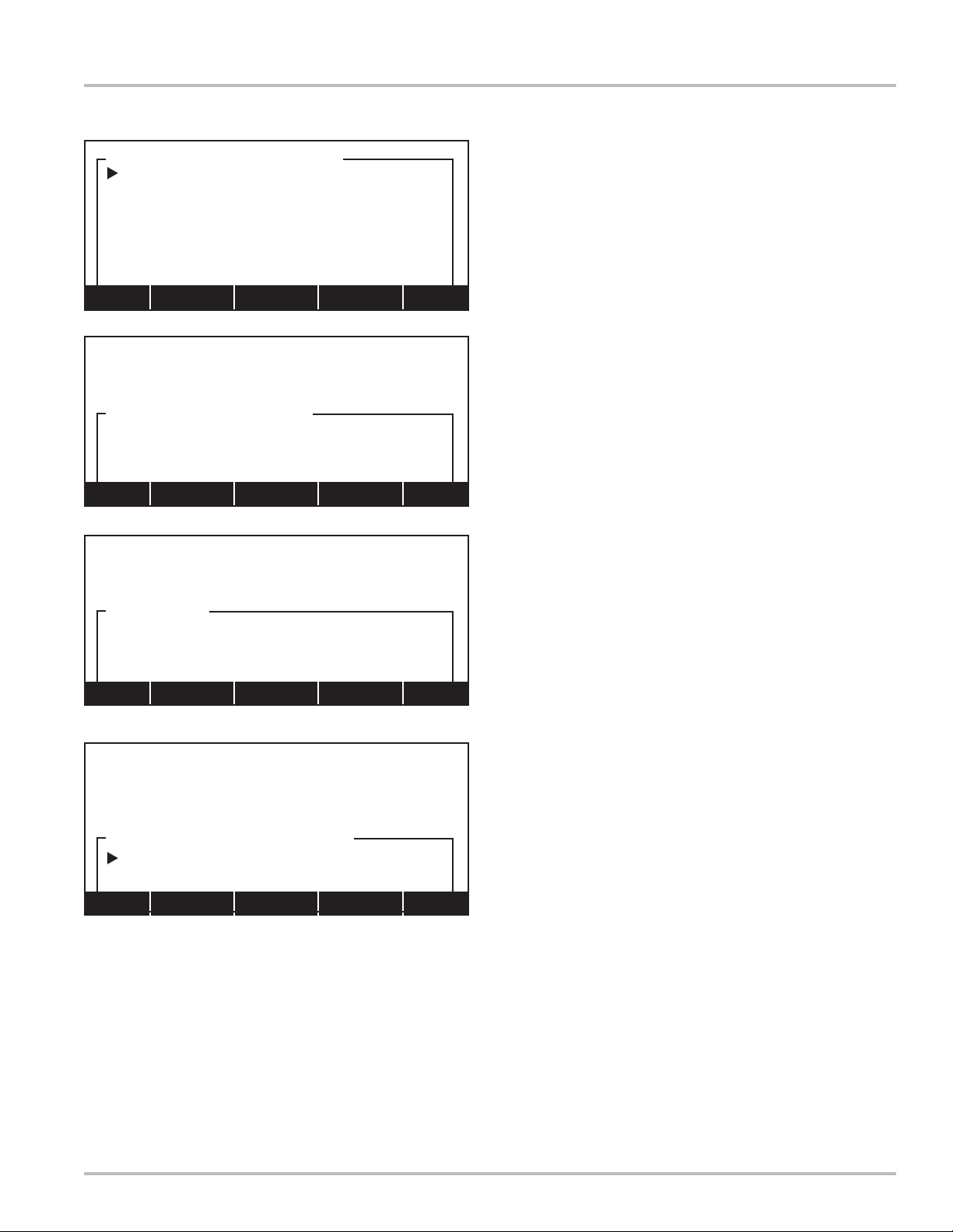
Screen 2a: System Utilities (1/3)
System Utilities consists of three screens. To advance
through these screens, press Next (F1). To exit this menu,
press Exit (F5).
Move pointer to Language and press ENTER to open a
list box window with options for the language to be used
by DMS i1000Menu. Move pointer to desired option and
press ENTER to accept.
Press Vers (F4) to open DMS i1000 Version Display
(shown below) which contains version numbers of the
application and supporting software libraries. There are
a minimum of six applications, it will be necessary to
scroll up and down to view all installed application version
numbers.
Data Management System v1.00
Welcome to the DMS i1000!
To set up your system, go to
SYSTEM UTILITIES by pressing
the F1/Util key.
Util
SYSTEM UTILITIES
Language:
(1/3)
English
DMS i1000 Password:
DMS i1000 Date Format:
DMS i1000 Date:
DMS i1000 Time:
MM/DD/YY
12/11/05
16:00:31
Next Vers Exit
SYSTEM UTILITIES
Language:
(1/3)
English
DMS i1000 Password:
DMS i1000 Version Display
Shows current version numbers of all installed applications
and supporting software libraries. Use PgDn (F4) to scroll
down to view version numbers.
DMS i1000 Date Format:
MM/DD/YY
Language
English
DMS i1000 Menu 1.02
(c) Liquid Controls LLC
ROM-DOS (c) Datalight Inc.
Support SDKs
PgDn End
12
Page 13
SYSTEM UTILITIES
Language:
(1/3)
English
DMS i1000 Password:
DMS i1000 Password
| |
Home <-- Ins --> End
System Utilities
Screen 2a: System Utilities (1/3)
System Utilities contain system critical information, an
option is provided to lock out this menu using a password.
Move pointer to DMS i1000 Password and press ENTER
to open a eld edit window.
Enter a password in the space provided. This can be
an alpha-numeric string of up to ten characters. Next,
press ENTER to accept password and close eld edit
window. Once password is entered, it will be required to
regain access to the System Utilities menu as well as
LCRHost and LCP File Server. Retain this password in
a safe place.
SYSTEM UTILITIES
Language:
(1/3)
English
DMS i1000 Password:
DMS i1000 Date Format
MM/DD/YY
DD/MM/YY
SYSTEM UTILITIES
Language:
(1/3)
English
DMS i1000 Password:
DMS i1000 Date
|12-11-05|
Home <-- Ins --> End
SYSTEM UTILITIES
Language:
(1/3)
English
DMS i1000 Password:
DMS i1000 Time
Move pointer to DMS i1000 Date Format and press
ENTER to open a list box window with options:
MM/DD/YY (month/day/year)
DD/MM/YY (day/month/year)
Move pointer to desired option and press ENTER to
accept.
Move pointer to DMS i1000 Date and press ENTER
to open a eld edit window. Enter date to be used by
LectroCount DMS i1000 and press ENTER to accept.
Three characters can be used as a separator: period (.),
dash (-), and colon (:).
Move pointer to DMS i1000 Time and press ENTER
to open a eld edit window. Enter time to be used by
LectroCount DMS i1000 and press ENTER to accept.
Press Next (F1) to advance to Screen 2b on page 14.
|16:00:31|
Home <-- Ins --> End
NOTE: It will be assumed that the operator can
now readily navigate list box windows and eld edit
windows. Therefore, these windows will no longer
be shown for the remainder of this section.
13
Page 14

System Utilities
Screen 2b: System Utilities (2/3)
Startup Caps Lock is used to designate whether the DMS
i1000Menu should boot with caps lock on or off. Press
ENTER to open a list box window with options Off or On.
Startup Insert Flag is used to designate whether the DMS
i1000Menu should boot with the system set to insert or
overwrite. Press ENTER to open a list box window with
options Off or On.
Ofce Node Address allows operator to specify LCP node
address used by an ofce computer when communicating
with a wireless transmitter. This can be any number in the
range from 0 to 255. Leave this set to 0.
Ofce Path is used to identify a path to where transaction
and database les are located on an ofce computer
when a wireless transmitter is in use. This can be an
alpha-numeric string up to 244 characters in length. As
an example:
C:\ or
C:\DMS i1000 or
C:\DMS i1000\DATA or
C:\SOURCE\DMS i1000
SYSTEM UTILITIES
Startup Caps Lock:
Startup Insert Flag:
Ofce Node Address:
Ofce Path:
USB Path:
C:\SOURCE\DMS i1000
D:\DMS i1000
(2/3)
Off
Off
255
Next Prev Exit
Leave this eld blank.
USB Path is used to identify path to where transaction
and data base les are located on the DMS i1000 USB
ash memory. This eld can be an alpha-numeric string
up to 244 characters in length. As an example:
D:\ or
D:\DMS i1000 or
D:\DMS i1000\DATA
Press Next (F1) to advance to Screen 2c on page 15.
Press Prev (F2) to return to Screen 2a on page 13.
Press Exit (F5) to exit System Utilities menu and advance
to Screen 3 on page 16. Screen 1 may not appear again
during normal operation.
14
Page 15

(3/3)SYSTEM UTILITIES
Upgrade DMS i1000 Software
Prev Exit
System Utilities
Screen 2c: SYSTEM UTILITIES (3/3)
Upgrade DMS i1000 Software is a function that enables
operator to upgrade system software of a LectroCount
DMS i1000 Module. Press ENTER to open a list box
window with options Yes or No.
Move pointer to Yes and press ENTER. Software on
the USB ash memory will load to ash memory of DMS
i1000 Module.
Press Exit (F5) to exit System Utilities menu and advance
to Screen 3 on page 16. Screen 1 may not appear again
during normal operation.
15
Page 16

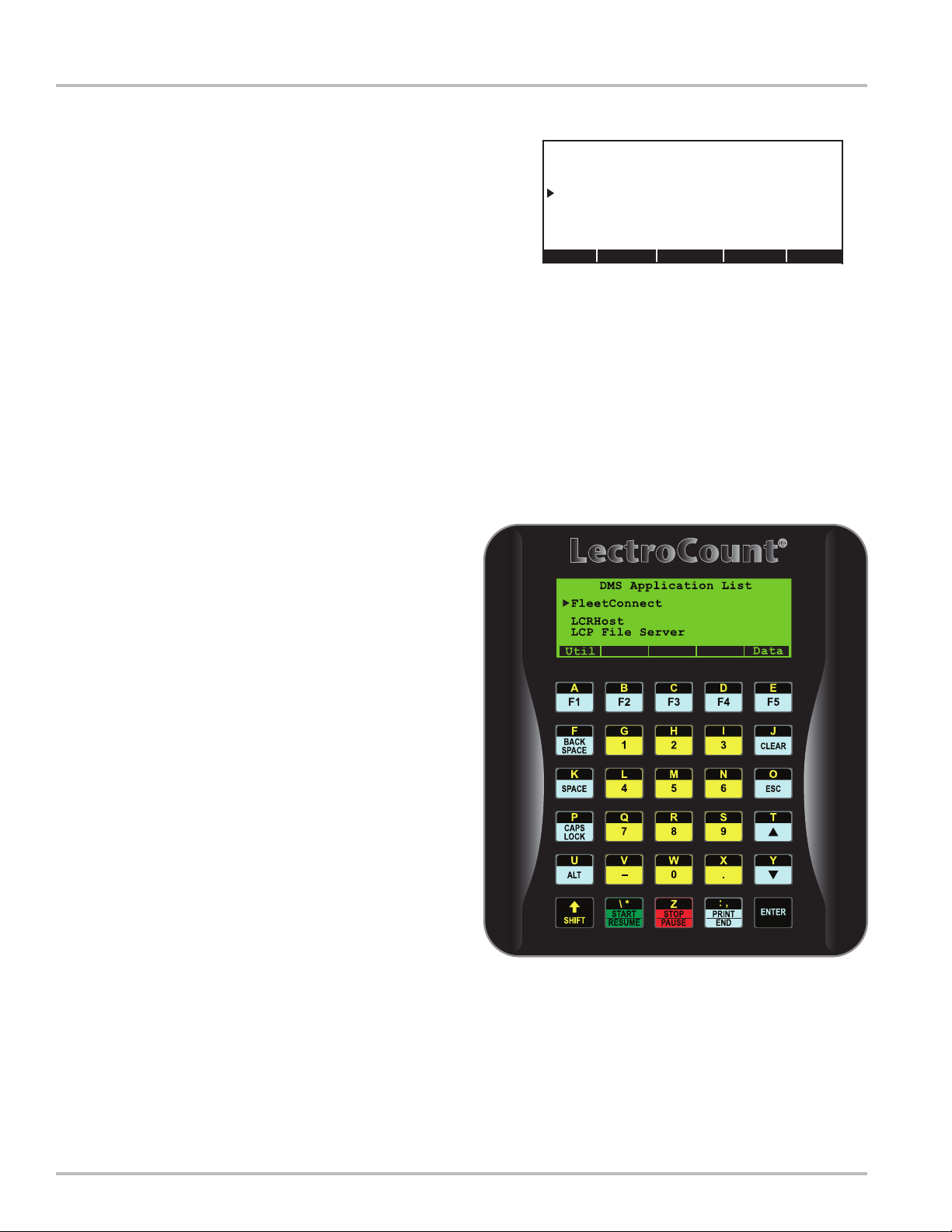
Data Application List
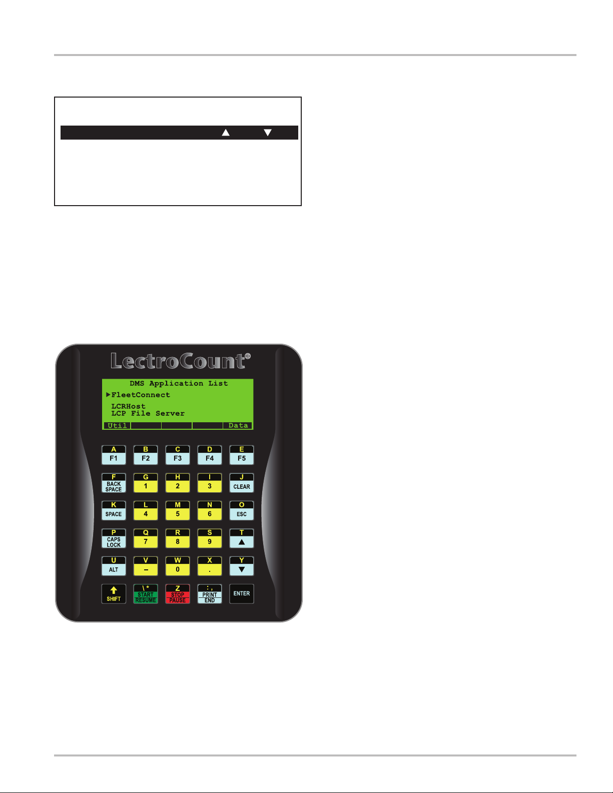
Screen 3: Data Management System
This screen is the main launch point for other applications
in the system. To access this screen, press ALT and ESC
simultaneously from any other application. This screen
must be accessed in order to navigate between available
applications. There is no direct link between LCRHost,
LCP File Server, and DMS i1000 Delivery. They must
all be accessed from this screen.
DMS i1000 Delivery
Application providing the operator ability to select
customers from a customized list, make deliveries, record
and track deliveries, review shift information, and transfer
completed delivery information to a DMS i1000 ofce
program using the USB ash memory.
The DMS i1000 Delivery application is not covered in
this publication. Refer to Operator’s Manual: 500344, for
detailed information on DMS i1000 Delivery Application.
LCRHost
Application provides operator ability to setup an LCR
Network, congure and calibrate a LectroCount register
and meter, and make deliveries.
DMS i1000 Application
List
DMS i1000 Delivery
LCRHost
LCP File Server
NOTE: PgUp (F2) and PgDn (F4) are activated only
if more applications are available than appear on the
screen.
The LCRHost application description begins on page
19.
LCP File Server
Provides operator ability to access hard drive of the DMS
i1000 interface from other computer systems.
The LCP File Server application description begins on
page 65.
Press Util (F1) to return to Screen 2a on page 12.
Press Data (F5) to advance to Screen 5 on page 17.
16
Page 17
Database Management
Send Transactions to Ofce
Retrieve Database from Ofce
USB Done
Database Management
Database Management
Screen 4: Database Management
Database Management screen is used to transfer
completed transaction les to an ofce computer and to
retrieve an updated database from an ofce computer.
Send Transactions to Ofce display is used to transfer
completed transaction les to an ofce computer. This
is typically done at the end of a shift or often as required.
When ENTER is pressed, appearance of the screens will
depend on the LectroCount DMS i1000 conguration.
To ensure system recognizes the USB memory device,
press USB (F3). This locates the USB memory device.
Once communication with USB memory device is
established, proceed with Send Transactions to Ofce
as described above.
Locating USB Drive...
USB Done
Database Management
Send Transactions to Ofce
Retrieve Database from Ofce
Send Mechanism
Radio
USB Memory Device
When ENTER is pressed, the system will transfer the
transaction le (CompTran.trn) to the USB ash memory.
A status indicator will appear and indicate progress of
le transfer. As this le is sent, the transaction records
are also automatically appended to an archive file
(CompTran.tra) in the DMS i1000. This archive le will
increase in size indenitely until deleted by the operator
via the LCR File Server application. When le transfer is
complete, the display will indicate:
“The transactions were successfully sent.
Press ENTER to proceed”.
Press ENTER to close this window.
Retrieve Database from Ofce display functions in
a similar fashion as Send Transactions to Office
display.
Move pointer to Retrieve Database from Ofce and
press ENTER. This will copy all les from the USB ash
memory with the extension “.slf” to DMS i1000 internal
ash memory. A transfer status indicator will display
progress of the le download. When complete, press
Done (F5) to return to Screen 3 on page 16.
17
Page 18

18
Page 19

LCRHost Application
19
Page 20
Main Menu
Screen 1: Program Initialization
When the LCRHost application is initialized at startup, screen to the right appears. This screen contains
information about the operating software. The rst line
contains program name and revision.
LCRHost v1.02
Welcome to LCRHost!
The message shown in lines 4-7 which appear after the
introduction lines, will then appear under the following
condition:
LCRHost detects that the LCRConfg.slf le does not
exist.
If system was already congured, the display will advance
to Screen 19a: Preset and Delivery (1/7) on page 54.
If communication cannot be established with the LCR,
then display will show Screen 20: Device Not Found
on page 59.
If this is the initial set and conguration of the system,
press Main (F5) to advance to Screen 2 shown below.
Screen 2: Main Menu
Main Menu is the launch point for system setup, calibration,
and conguration. Items appearing on the Main Menu are
typically used for initial setup and conguration of the
system but may be reset should the system or application
change.
By default, the pointer position will be the rst available
function on the screen. To move pointer from Setup
Network to another line, use up or down arrow of the
DMS i1000 Lap Pad. The up arrow is on shares T key
and down arrow shares Y key.
To set up your network, go to
the Main Menu by pressing the
F5/Main key.
Main
LCRHost v1.02
MAIN MENU
Setup Network
System Parameters
Congure LCR #xxx
Save Conguration
Load Conguration
Dlvy LCR#
Setup Network
Advances display to Screen 3 on page 21.
System Parameters
Advances display to Screen 6a on page 26.
Congure LCR#
Advances display to Screen 7 on page 28.
Save Conguration
Advances display to Screen 14 on page 51.
Load Conguration
Advances display to Screen 15 on page 52.
Dlvy appears above function key F1. Press Dlvy (F1) to
advance to Screen 19a on page 54.
LCR# appears above function key F4. Press LCR# (F4)
to open a list box window with options for selecting an
LCR to communicate with.
Press Esc to exit list box window. Move pointer to Setup
Network and press ENTER to advance to Screen 3 on
page 21.
20
Page 21
SETUP NETWORK
Steps to create a new network.
F3/New: Create a new network.
Edit Port eld if necessary.
F1/Next:Setup device database.
F1/Next:Setup network devices.
New Main
SETUP NETWORK
(1/3)
Network #:
Name:
Port:
COM2 at 19200 Baud
Next New Del Main
SETUP NETWORK
(1/3)
Network #:
Network Number
1 :1-METER SYSTEM
2 :2-METER SYSTEM
3 :3-METER SYSTEM
Setup Network
Screen 3: Setup Network
If no network les have been set up, the screen to the
right will be displayed. This display is not editable, but
indicates the steps to be taken to set up a new network.
Press New (F3) to create a new network. This advances
the display to Screen 4a shown below.
NOTE: The default values for each of the SETUP
NETWORK elds will effectively communicate with a
LectroCount register.
Screen 4a: Setup Network (1/3)
The SETUP NETWORK screens allow a new installation
to dene the network. There are two editable items on this
rst of these screens. The rst eld, Network #, opens
a list box window with a default set of network identiers.
If this is a single meter network, select 1 |1-METER
SYSTEM. This populates Network # and Name elds
for this screen.
If a different Network # and Name are required, a new
network can be established. Initiated by pressing New
(F3).
New opens a eld edit window. Network Number can
have a numeric value from 1 to 65535. Enter a number
and press ENTER to accept the value. For example, enter
1 as the Network Number and press ENTER.
Move pointer to Name and press ENTER to open a eld
edit window. Network Name is an optional eld and can
be a maximum length of 14 alpha-numeric characters.
Enter desired Network Name and press ENTER to accept
the value. For example, enter TRUCK 2112 then press
ENTER.
SETUP NETWORK
(1/3)
Network #:
Name:
Single Meter
Network Name
|1-METER SYSTEM|
Home <-- Ins --> End
If more than one network is required for the application,
press New (F3) to enter next Network Number.
To delete a Network #, select that network number from
the list box window, press ENTER, and then press Del
1
(F4) to delete that network from the program.
When task is complete, press Port (F2) to advance to
Screen 5: Setup Network Port on page 24.
21
Page 22
Setup Network
Screen 4b: Setup Network (2/3)
This screen is used to establish communication with
LectroCount Registers (LCRs). By default, all LCRs are
shipped with a node address of 250. This information
will be helpful when establishing communication with
new LCRs.
Based on examples provided, one network has been
dened and this is Network # 1. Move pointer to Device
and select New (F3) The device number can be between
1 and 249. Enter the number “1” and press ENTER to
accept.
Next, move pointer to Name and press New (F3) to open
a eld edit window. This eld can be from 0 to 16 alpha-
numeric characters in length. Enter a suitable name for
the device number 1. For example, type in “LCR1” and
press ENTER to accept.
SETUP NETWORK
Network:
1|1-METER SYSTEM
(2/3)
Device:
Name:
METER-1
1
Next Prev New Del
SETUP NETWORK
Network:
1|1-METER SYSTEM
(2/3)
New Device Number
|1_ |
Home <-- Ins --> End
SETUP NETWORK
Network:
1|1-METER SYSTEM
(2/3)
Device:
Name:
METER-1
1
Next Prev New Del
SETUP NETWORK
Network:
1|1-METER SYSTEM
(2/3)
Device Name
|METER-1 |
Home <-- Ins --> End
22
Page 23
SETUP NETWORK
Network:
1|1-METER SYSTEM
(3/3)
======SEARCH FOR DEVICES======
First Device:
Last Device:
Prev Addr Srch Setup
SETUP NETWORK
Network:
1|1-METER SYSTEM
(3/3)
Set Up LCR Devices
No
Yes
Setup Network Devices
Screen 4c: Setup Network (3/3)
Move pointer to Last Device and enter Setup (F5) this
allows automatic selection of an active LCR device.
Under Set Up LCR Devices, move pointer to Yes then
press ENTER. This will display The setup process has
completed successfully.
1
1
When a new device is found, enter a name for it and
continue with setup.
To remove a device from the network conguration, select
device and press Del (F4). This deletes the selected
device. Deleting a device connected to the network
will cause it’s node address to be reset to 250. When
programming of network devices is complete, press Exit
(F5) to return to Screen 4a on page 21. Then press Main
(F5) to return to Screen 2 on page 20.
Move pointer to System Parameters and press ENTER
to advance to Screen 6a on page 26.
SETUP NETWORK
Network:
1|1-METER SYSTEM
(3/3)
Finding active device
Last Device:
Prev Addr Srch Setup
LCRHost: 31025
The setup process has
completed successfully.
Press ENTER to proceed.
Last Device:
Prev Addr Srch Setup
NOTE: It will be assumed the operator can now
readily navigate list box windows and eld edit
windows. Therefore, these windows will no
longer be shown for remainder of this manual.
23
Page 24
Setup Network
Screen 5: Setup Network Port
Setting up network port sets up communication parameters
between LectroCount DMS i1000 and LectroCount
electronic register.
Port is used to select the port and interrupt request line
used by the active network. Press ENTER to open a list
box window for Communications Port. The following
options will be available:
COM1
COM2
COM3
COM4
Use Base Address of UART
A standard DMS i1000 Module is wired to communicate
with the LCR network on COM2, IRQ3, at a baud rate of
19200, therefore select COM2 and press ENTER. This will
open another list box window. The new list box window is
for selecting the IRQ used by the port. This list box window
contains interrupt request (IRQ) values between 2 and 15.
Select IRQ “3” and press ENTER to accept the COM and
IRQ choices and return to SETUP NETWORK PORT.
The changes for Port are now displayed on the screen.
Move pointer to Bits/Second (baud rate) and press
ENTER. This opens the Bits/Second list box window.
This value is the baud rate used to communicate with the
network of LectroCount registers. The following options
are available:
2400
4800
9600
19200
57600
It is recommended to use a baud rate of 19200. Select
19200 and press ENTER to accept the value. If there is
no printer connected to the system, a baud rate of 57600
can be selected.
SETUP NETWORK PORT
Port:
Bits/Second (Baud):
Tx Enable Bit:
Maximum Retries:
Timeout (ms):
Baud Synchronization :
COM2 using IRQ 3
19200
RTS
1
100
Yes
Exit
SETUP NETWORK PORT
Communications Port
COM1
COM2
COM3
COM4
Use Base Address of UART
IRQ
3
4
5
6
7
8
Home PgUp Find PdDn End
SETUP NETWORK PORT
Bits/Second
2400
4800
9600
19200
57600
24
Page 25
Transmit Enable Bit
!RTS
!RTS!DTR!
DTR
None
RTS
RTSDTR
Home PgUp Find
SETUP NETWORK PORT
Port:
Bits/Second (Baud):
COM1 using IRQ 3
19200
Maximum Retries:
|1_ |
Home <-- Ins --> End
SETUP NETWORK PORT
Port:
Bits/Second (Baud):
COM1 using IRQ 3
57600
Timeout:
|250_|
Home <-- Ins --> End
Setup Network
Screen 5: Setup Network Port
Continued
Move pointer to Tx Enable Bit and press ENTER to open
Transmit Enable Bit list box window. The Transmit
Enable Bit is used in an RS-485 network when data is to
be transmitted to a LectroCount register. The following
options are available:
!DTR
!RTS
!RTS!DTR
DTR
None
RTS
RTSDTR
For a standard DMS i1000 Module, select RTS and press
ENTER to accept the value.
Move pointer to Maximum Retries and press ENTER to
open a eld edit window.
Maximum Retries represents number of times system
attempts to communicate with a LectroCount register
should rst attempt fail. The maximum number of retries
can have a value between 0 and 255. Enter desired
number of retries and press ENTER to accept the value.
Move pointer to Timeout and press ENTER to open a
eld edit window. Timeout value is the length of time (in
milliseconds) a single communication is attempted before
returning a communication failure. The timeout value may
be between 100 and 9999 ms. Enter desired value and
press ENTER to accept. The recommended value is 100.
SETUP NETWORK PORT
Port:
COM1 using IRQ 3
Bits/Second (Baud):
Tx Enable Bit:
Baud Synchronization
No
Yes
19200
RTS
Move pointer to Baud Synchronization and press
ENTER to open a list box window and chose Yes or No. If
Yes is selected, the system will try all available baud rates
should the baud rate set earlier result in a communication
error. Select Yes and press ENTER to accept.
NOTE: Care should be taken when setting the Maximum
Retries and Timeout values. If an LCR is not present in
the network, it will take:
5 x (R + 1) x T = milliseconds
before it is determined an LCR is not present. 5 is the
number of baud rates if Baud Synchronization is set to
Yes, R is the number of Maximum Retries and T is the
Timeout value in milliseconds. If the number of retries
is 3 and the timeout value is 500, then the time before an
error is returned is:
5 x (3 + 1) x 500 = 10,000 or 10 seconds.
Press Exit (F5) to exit SETUP NETWORK PORT and
return to SETUP NETWORK. Then press Dev (F1) to
advance to Screen 5: SETUP NETWORK DEVICES on
page 24.
25
Page 26

System Parameters
Screen 6a: System Parameters (1/2)
System Parameters screens are used to set up user
interface and system information.
Move pointer to Language and press ENTER to open a
list box window of languages. Select desired language
to be used by LCRhost and displayed on the DMS i1000
Lap Pad. Language options currently include English.
Move pointer to LCRHost Password and press ENTER
to open a eld edit window. Enter an alpha-numeric code
up to 10 characters in length. Once LCRHost Password
is entered, the operator is required to enter this code in
effort to access the Main Menu from delivery screens.
NOTE: If password protection of Main Menu is not
desired, leave this eld blank.
The elds are for setting date and time of LCRHost
processor (not the LCR). Date and time are eld edit
windows. Enter current date and time for each eld.
Date/Time Master designates which device will have the
master copy of the date and time. When a new delivery
is started, date and time from the master device will
be sent to a slave device. Move pointer to Date/Time
Master and press ENTER to open a list box window with
the options:
SYSTEM PARAMETERS
Language:
(1/2)
English
LCRHost Password:
Host Date:
Host Time:
Date/Time Master:
01/16/06
16:00:23
Host
Next Vers Main
HOST
LCR
None
If HOST is selected, date and time are maintained in the
LCRHost processor. When a delivery is started, HOST
date and time will be sent to the LCR. If LCR is selected,
date and time are maintained in the active LCR to be
retrieved and set in the LCRHost processor at start of
each delivery.
If None is selected, then date and time will not be
synchronized between LCRHost processor and active
LCR. Date and time information appearing on delivery
ticket will be from the LCR.
Press Next (F1) to advance to Screen 6b on page 27.
Press Vers (F4) to open DMS i1000 About Display shown
on the bottom of page 12.
26
Page 27

SYSTEM PARAMETERS
Startup Caps Lock:
Startup Insert Flag:
(2/2)
Off
Off
Prev Main
LCRHost (DMS i1000) v1.02
MAIN MENU
Setup Network
System Parameters
Congure LCR # 1
Save Conguration
Load Conguration
Dlvy LCR#
System Parameters
Screen 6b: System Parameters (2/2)
Startup Caps Lock is used to designate whether the
DMS i1000 Lap Pad should boot with caps lock on or off.
Pressing ENTER opens a list box window with options
Yes or No.
Startup Insert Flag is used to designate whether the DMS
i1000 Lap Pad should boot with the system set to insert
or overwrite. Pressing ENTER opens a list box window
with the options Yes or No.
When programming of this screen is complete, press Main
(F5) to return to the MAIN MENU (shown to the right),
move pointer to Congure LCR# 1, and press ENTER
to advance to Screen 7 on page 28.
27
Page 28

Congure LCR
Screen 7: Congure LCR
Network and LCR Device must be assigned rst.
Congure LCR is similar to Main Menu as a launching
point for several other sub-menus. Within Congure
LCR are:
General Setup
Advances display to Screen 8a on page 29.
1CONFIGURE LCR
General Setup
System Calibration
Product Calibration
Diagnostics
Security
System Calibration
Advances display to Screen 9a on page 32.
Product Calibration
Advances display to Screen 10a on page 37.
Diagnostics
Advances display to Screen 11a on page 48.
Security
Advances display to Screen 12 on page 49.
Pressing Stat (F3) advances display to Screen 21 on
page 60.
Pressing LCR# (F4) allows the operator to select the
LectroCount register to be congured.
Pressing Main (F5) returns display to Screen 2 on page
20.
Ensure pointer is on General Setup and press ENTER
to advance to Screen 8a on page 29.
Status LCR# Main
28
Page 29

GENERAL SETUP
(1/5) 1
Unit ID:
Presets Allowed:
Net
Date Format:
Date:
Time:
MM/DD/YY
01/11/05
11:27:36
Next Cnfg Main
General Setup
Screen 8a: General Setup (1/5)
General Setup screens are used to set up system
information, deliveries, and ticket printing.
Unit ID is an alpha-numeric identier up to 10 characters
in length used to identify the active LectroCount register.
Press ENTER to open a eld edit window and enter
desired value. Press ENTER to accept.
Presets Allowed denes presets an operator can set
while making deliveries. Preset deliveries allow an
operator the ability to enter a preset volume for delivery.
Upon reaching the preset volume, LectroCount will
typically close a security valve (if equipped) and print a
delivery ticket.
There are four options for Presets Allowed.
BOTH - for both net and gross presets
GROSS - for gross (non-compensated) presets only
NET - for net (temperature compensated) presets
or
NONE - for no presets allowed
Move pointer to desired option and press ENTER to
accept.
NOTE: If the preset feature is used, ensure the S1 CLOSE
eld on page 38 is set for a preset value to work properly.
Date Format is used to determine the format date
displayed and printed. Press ENTER to open a list box
window with the options: DD/MM/YY (Day/Month/Year)
and MM/DD/YY (Month/Day/Year). Select desired format
and press ENTER to select.
Date and Time are elds where current date and time
are entered for the LCR (not for LCRHost). Open the
eld edit window for each and enter current date and
time. Three characters used as a separator are period (.),
forward slash (/), and colon (:). Press ENTER to accept
each value.
Pressing Next (F1) advances display to Screen 8b on
page 30.
Pressing Cnfg (F4) returns display to Screen 7 on page
28.
Pressing Main (F5) returns display to Screen 2 on page
20.
29
Page 30

General Setup
Screen 8b: General Setup (2/5)
Sale # is used to track number of transactions LectroCount
processes. This number will increment each time a
delivery is started.
Press ENTER to open a eld edit window to enter starting
number for Sale # and press ENTER to accept. The
LectroCount will use this as the starting value for Sale #
and increment by 1 each time a delivery is started. Once
a Sale # reaches 999999, it will return the count to zero
and resume counting from 1.
GENERAL SETUP
(2/5) 1
Sale #:
Ticket #:
Print Gross & Parameter?
Volume Corrected Message?
Pulse Output Edge:
Falling
Yes
Yes
Next Prev Cnfg Main
1
1
Ticket # is similar to Sale # however, Ticket # will
increment each time LectroCount prints a ticket.
If multiple or duplicate tickets are used for transactions,
the ticket number will increment more than the Sale #.
Press ENTER to open a eld edit window and enter
starting number for Ticket # and press ENTER to accept.
LectroCount will use this as the starting value for Ticket #
and increment by 1 each time a delivery ticket is printed.
Once Ticket # reaches 999999, it will return the count to
one and resume counting from 1.
NOTE: If 0 is entered for Ticket #, the Ticket # will not
print on the delivery ticket and it will not increment.
Print Gross & Param? is used to enable or disable
printing of gross volume and compensation parameter
on the delivery ticket if the product is temperature
compensated. In many applications this is required.
Check local Weights & Measures requirements.
Press ENTER to open a list box window. Select No if it is
NOT desired to print the gross volume and compensation
parameter on the ticket. Select Yes if it IS desired to
print the gross volume and compensation parameter on
the ticket.
Volume Corrected Message? is used to enable or disable
printing of the base temperature of net deliveries on the
delivery ticket. In many applications, this is required.
Check local Weights & Measurements requirements.
There are two options for Vol Corrected Msg?. Select
No if the volume corrected message is NOT printed on the
delivery ticket. Select Yes to have the volume corrected
message printed on the delivery ticket. If Yes is selected,
the LectroCount will print a message on the delivery ticket
indicating the delivery volume has been corrected to a
specied base temperature.
If base temperature is in °C, the message will read:
TEMPERATURE VOLUME CORRECTED TO 15 °C
If the base temperature is in °F, the message will read:
TEMPERATURE VOLUME CORRECTED TO 60 °F
NOTE: The base temperature for Linear C and Linear F
can be set to a value other than their default values.
All LectroCount registers feature a calibrated pulse output
which cycles once per least signicant unit of delivery.
The Pulse Out Edge eld allows the LectroCount to
synchronize the calibrated pulse output waveform with the
requirements of an external counter. Depending on the
manufacturer, some counters may increment on the rising
pulse edge of the waveform, some on the falling pulse
edge. Refer to the manufacturer’s manual to determine
the specic requirements.
The List Box Window has two options. Select Rising for
the rising edge of the pulse output. Select Falling for the
falling edge of the pulse output.
Press Next (F1) to advance to Screen 8c on page 31.
30
Page 31

(3/5) 1GENERAL SETUP
Header Text
1:
2:
3:
4:
5:
Next Prev Cnfg Main
(4/5) 1GENERAL SETUP
Header Text
6:
7:
8:
9:
10:
Next Prev Cnfg Main
General Setup
Screen 8c: General Setup (3/5)
The next three consecutive screens all deal with header
information to be printed on a delivery ticket. The header
lines are edited individually. Press ENTER to open a eld
edit window for each line. Enter alpha-numeric information
up to 35 characters in length per line. Any or all of these
elds may be left blank.
NOTE: Since display is set to 30 character width, header
text information may scroll off the screen. This will be
indicated by ›› at the end of the header text line. All
information will, however, print on the delivery ticket.
Screen 8d: General Setup (4/5)
Header lines 6 through 10. Refer to description above.
(5/5) 1GENERAL SETUP
Header Text
11:
12:
Prev Cnfg Main
Screen 8e: General Setup (5/5)
Header lines 11 and 12 print conditionally. Header line
11 prints only if Aux1 is set to ON DURING DELIVERY.
Similarly, Header line 12 prints only if Aux2 is set to ON
DURING DELIVERY. For example, if an additive injector
is activated by Aux1, it may be desirable to note this on
the ticket by adding a header line such as “Prist added
to this delivery”.
Press Cnfg (F4) to return to Screen 7 on page 28. Move
the pointer to System Calibration and press ENTER to
advance to Screen 9a on page 32.
31
Page 32

System Calibration
Screen 9a: System Calibration (1/5)
System Calibration screens cover configuration and
calibration of the metering system.
Meter ID is an alpha-numeric value used to uniquely
identify a Meter attached to a LectroCount register. It is
important a unique number is selected and recommended
the meter serial number be entered. This number will
print on all calibration and diagnostic tickets for future
reference.
Press ENTER to open a eld edit window and enter a
unique identier up to 10 alpha-numeric characters in
length. Press ENTER to accept this value.
Flow Direction is used to set direction of ow through
the meter. If the LectroCount display counts in reverse
(decreasing numbers) after unit is installed, it will be
necessary to select opposite Flow Direction.
Ticket Required is used to select whether a delivery
ticket will be required for each delivery. Most Weights
& Measures governed truck applications will require a
ticket.
There are two options for Ticket Required?. If No is
selected, the system will NOT require a ticket to be printed
after each delivery. If Yes is selected, the LectroCount
will not allow deliveries to be made unless a ticket is in the
printer and the printer is operational. It will also require a
ticket be printed before another delivery can be started.
SYSTEM CALIBRATION
Meter ID:
Flow Direction:
Ticket Required?
Printer
Epson OldFontA
dP Shutdown Value:
(1/5) 1
4545
->
Yes
xx.x
Next Cnfg Main
dP Shutdown Value represents differential pressure
that will cause current active delivery to shutdown. This
function is only active when the following conditions
exist:
1. A Differential Pressure device is installed.
2. LectroCount Register has SR214 software installed.
3. Value is set to a number other than “0”
When these three conditions exist, reaching or exceeding
the dP Shutdown Value will end the delivery. Press
ENTER to open a eld edit window and enter a value
between 0 and 59.9.
Press Next (F1) to advance to Screen 9b on page 33.
Move pointer to desired option and press ENTER to
accept.
NOTE: Selecting No will still allow a ticket to be printed
if a printer is connected, loaded with paper, and ready
to print.
Printer is used to select printer model to communicate
with the LectroCount. Selecting a wrong printer model
may result in miscommunication between LectroCount
and printer.
There are six options for the Printer. Use the following
guide to select the correct option:
BLASTER (select for use with Cognitive Solutions
Thermal Printer).
EPSON NewFontA (select for use with EPSON TM-
T88iii)
EPSON NewFontB (select for use with EPSON 200 Roll
and EPSON 220 Roll)
EPSON OldFontA (select for use with EPSON 290 Slip
and EPSON 295 Slip)
EPSON OldFontB (select for use with EPSON 300
Roll)
Okidata ML184T (select for use with Okidata ML184T)
32
Page 33

SYSTEM CALIBRATION
Units of Measure:
Flow Rate Base:
Decimals:
Residual Processing
(2/5) 1
Gallons
Per Minute
Hundreths
Truncate
Next Prev Cnfg Main
System Calibration
Screen 9b: System Calibration (2/5)
Units of Measure is used to dene base unit of measure
for delivery quantities. Press ENTER to open a list box
window with the options:
Gallons
Litres
Cubic M
LBS
KGS
Barrels
Other
Move pointer to selection and press ENTER.
Flow Rate Base is used to dene rate base used by ow
rate eld. Press ENTER to open a list box window with
the options:
Per Hour
Per Minute
Per Second
Move pointer to desired option and press ENTER.
Decimals is used to dene the number of digits maintained
to right of decimal point in quantity elds. Press ENTER
to open a list box window with the options:
Hundredths = 2 decimal places (e.g. 120.22)
Tenths = 1 decimal place (e.g. 120.2)
Whole = 0 decimal places (e.g. 120)
Move pointer to desired option and press ENTER.
Residual Processing is used to dene what happens
with residual amounts. Press ENTER to open a list box
window with the options:
Round
Truncate
Selecting Round causes quantity residuals to be rounded
in the displayed values. Selecting Truncate causes
quantity residuals to be truncated from the display values.
For example, if actual quantity registered is 100.26 and
Decimals is set to Tenths, the Round value would be
100.3, and Truncated value would be 100.2.
Press Next (F1) to advance to Screen 9c on page 34.
33
Page 34

System Calibration
Screen 9c: System Calibration (3/5)
The rst three items on this screen are used to dene
parameters of an odometer sensing device (if installed
as part of the LCR).
The elds of Pulses/Distance, Calibrated Distance, and
Odometer are used to calibrate an odometer pulser if an
odometer input is being used with an LCR.
NOTE: LectroCount LCR-II does not have an odometer
input option. If the register is required to maintain an
odometer reading, use LectroCount LCR.
Pulses/Distance represents number of pulses from an
odometer pulser the LectroCount LCR counts per unit of
distance (miles or kilometers). For initial calibration of the
odometer, enter 4000 as a starting point. The frequency
of the odometer pulser must be no more than 25 pulses
per second or inaccuracies will result.
SYSTEM CALIBRATION
Pulses/Distance:
Calibrated Distance:
Odometer:
Password Usage:
Customer Usage:
(3/5) 1
2.000000
--------
0.0
Delivery
Delivery
Next Prev Cnfg Main
Customer Usage allows operator to specify when
customer number will be required on the front panel of
the LCR-II. Press ENTER to open a list box window with
the options:
Delivery
None
If odometer feature is not being used, this number must
be set to 2.
If LCR odometer input terminals are being used for
optional START/STOP feature, Pulses/Distance must
be set to “0”.
Calibrated Distance is used to calibrate the odometer.
To begin odometer calibration, enter “0” for Calibrated
Distance. Drive vehicle a known distance (minimum of 5
miles recommended) using truck’s odometer for reference.
Enter actual distance traveled in the Calibrated Distance
eld. This will automatically adjust Pulses/Distance to
reect corrected number.
Odometer represents truck’s odometer once odometer
function has been calibrated.
Enter truck’s current odometer reading in Odometer eld
edit window. Press ENTER to accept value.
NOTE: The next two elds will only be displayed when a
LectroCount register has software SR216 installed.
Password Usage is used to determine when a password
will be required on front panel of the LCR-II. Press ENTER
to open a list box window with the options:
Select None to indicate customer number will not be
required and will be set to 0 for each delivery.
Select Delivery to indicate customer number will be
required for each delivery.
Press Next (F1) to advance to Screen 9d on page 35.
Delivery
None
Shift
Select None to indicate password eld will not be used.
Select Delivery to specify password will need to be
entered before each delivery.
Select Shift to specify password will need to be entered
before each shift.
34
Page 35

SYSTEM CALIBRATION
Temperature:
Offset:
Temperature Unit:
(4/5) 1
80.54
.30
Deg. F
System Calibration
Screen 9d: System Calibration (4/5)
Tempera t u r e displays current reading from the
temperature probe with the offset applied. If LectroCount
is not equipped with a temperature probe, the display will
show dashes. This eld allows entry from a Weights &
Measures calibrated thermometer.
RTD Slope:
RTD Offset:
0.025000
0.000
Next Prev Cnfg Main
To calibrate temperature probe, run enough product
through the meter to allow temperature to stabilize.
Compare Temperature reading with current Weights &
Measures thermometer reading. If the readings do not
match, enter the Weights & Measures reading in the eld
edit window for Temperature. This value will overwrite
the previous value and the Offset eld will be recalculated
by the LectroCount.
Offset adjustments are limited to ±0.3°C (±0.54°F).
Adjustments greater than these offset values require
replacement of the RTD Probe.
Offset represents the difference between the ofcial
Weights & Measures temperature reading and the
LectroCount probe’s temperature reading. The offset
is automatically calculated if an entry is made in the
Temperature eld. If a temperature probe is not present,
this eld will show dashes.
If a Weights & Measures temperature reading was not
entered in Temperature, subtract Temperature value
from Weights & Measures temperature reading. Enter this
value in the eld edit window for Offset. If the difference
is a negative number, enter “-” before the value.
Offset adjustments are limited to ±0.3°C (±0.54°F).
Adjustments greater than these offset values require
replacement of the RTD Probe.
Temperature Unit is used to dene the temperature
unit to be used for the application. The two options for
Temperature Unit are Deg. C (degrees Celsius) and Deg.
F (degrees Fahrenheit). Move pointer to desired option
and press ENTER to accept.
RTD Slope and RTD Offset are used for factory calibration
of the LectroCount and are not editable.
RTD Slope indicates slope used to calculate the raw
temperature value from the raw ADC value.
RTD Offset indicates offset used to calculate the raw
temperature value from the ADC value.
Press Next (F1) to advance to Screen 9e on page 36.
35
Page 36

System Calibration
Screen 9e: System Calibration (5/5)
These calibration information elds are for metrology use
and are not editable.
Calib Date displays date and time when the red selector
switch on the LectroCount register was last moved from
the calibration position to SHIFT PRINT position.
Calib Number displays number of times the red selector
switch of the LectroCount has been switched from the
calibration position to SHIFT PRINT position.
Calib Event displays number of times a calibration event
has occurred.
Cong Event displays number of times a conguration
event has occurred.
For more information on Calib Event and Cong Event,
refer to page 64.
Press Cnfg (F4) to return to the Screen 7 on page 28.
From there, move pointer to Product Calibration and
press ENTER to advance to Screen 10a on page 37.
SYSTEM CALIBRATION
Calib Date:
01/11/05 11:50:25
(5/5) 1
Calib Number:
Calib Event:
Cong Event:
24
29
Prev Cnfg Main
1
36
Page 37

PRODUCT CALIBRATION
Product #: X
Units: Gallons
(1/6) 1
Product Code:
Name:
Product Type:
Gasoline
Next Cnfg Main
Product Calibration
Screen 10a: Product Calibration (1/6)
Product Calibration screens are used to calibrate the
metering system for product(s) which will be measured.
Product # is used to select product number to be
calibrated. The product number will correspond to one of
the product types/calibrations set up in the LectroCount.
At least one product must be calibrated to allow for
deliveries. Press ENTER to open a list box window with
options: 1, 2, 3, or 4.
Product Code will correspond to the Product Number.
The Product Code can also be entered in the Preset
and Delivery menu. Press ENTER to open a eld edit
window. Enter a alphanumeric product code up to ve
characters in length.
Name contains a description of the product that will appear
on the delivery ticket. Press ENTER to open a eld
edit window and enter an alphanumeric name up to 18
characters in length. Ensure product Name is descriptive
of the Product Type and Product Code.
Product Type is used to specify type of product to be
delivered. Press ENTER to open a list box window with
the following eight options:
Ammonia
Aviation
Distillate
Gasoline
Methanol
LPG
Lube Oil
(blank)
Move pointer to desired Product Type and press ENTER
to accept. If (blank) is selected, it indicates there is no
product type associated with the product being calibrated
and delivered.
Press Next (F1) to advance to Screen 10b on page 38.
37
Page 38

Product Calibration
Screen 10b: Product Calibration (2/6)
If temperature volume compensation is being used for
deliveries, the type of temperature volume compensation
must be selected for the Product #. It is necessary
to make a selection for proper Net (temperature
compensated) calculations.
Move pointer to Comp Type and press ENTER to open
a list box window with the following options:
None
Linear F
Linear C
Table 24
Table 54
Table 6B
Table 54B
Table 54C
Table 54D
NH3
Move pointer to desired option and press ENTER to
accept.
NOTE: If None is selected, deliveries can only be made
in gross (non-compensated) quantities.
PRODUCT CALIBRATION
Product #: 1
Units: Gallons
(2/6) 1
Comp Type:
Comp Parameter:
Base Temperature:
S1 Close:
10.0
Next Prev Cnfg Main
window and enter a number in this eld based on the
following guideline:
Selection Range
Linear F -130.0 to 212.0
Linear C -90.0 to 100.0
S1 Close represents the number of measurement units
remaining on a preset delivery before the valve is placed
in a bypass, trickle, or dwell mode. This eld is only used
when a two-stage valve is used in the application and
is connected to the LectroCount register. An S1 Close
value must be set for each product if presetting is being
employed.
Refer to Compensation Types and Parameters table on
page 39 to assist in making the correct selection.
Comp Parameter is the coefcient of expansion per
degree, the base temperature density, the API gravity,
or the base temperature specic gravity that will be used
with the Comp Type selected. Press ENTER to open a
eld edit window and enter a value based on the following
guideline:
Selection Range
None 0.0
Linear F 0.0000 to 0.0025 (per °F)
Linear C 0.000 to 0.005 (per °C)
Table 24 0.500 to 0.550 (SGU)
Table 54 0.500 to 0.600 (KG/Litre)
Table 6B 0.0 to 85.0 (°API)
Table 54B 653.0 to 1075.0 (KG/M³)
Table 54C 0.000486 to 0.001674 (per °C)
Table 54D 800.0 to 1164.0 (°API)
NH3 N/A
If Comp Type selection is either Linear C, or Linear F,
then Base Temp is used to set the base temperature for
temperature compensated deliveries.
If Linear C is selected for Comp Type, the Base Temp
value will default to 15.0 (for 15 °C). If Comp Type is
set to Linear F, the Base Temp default value is 60.0 (for
60°F).
When the S1 Close value is reached, Solenoid 1 is
deactivated and Solenoid 2 is activated.
For example: If value entered is 10 and the preset delivery
is set to 100, then S1 will close and S2 will open when the
register reaches 90. This reduces the delivery ow rate,
slowing down the ow of product through the meter.
Press ENTER to open eld edit window and enter a value
between 0.0 and 99999.0. It is recommended not to use
a value smaller than 10% of preset volume.
Press Next (F1) to advance to Screen 10c on page 40.
To change this value, press ENTER to open a eld edit
38
Page 39

Compensation Types and Parameters
Product Calibration
Product VCF Type
General
General
LPG
USA
LPG
Europe & Canada
Refined Petroleum Products
Europe & Canada
Refined Petroleum Products
USA
General
Lube Oil
Europe & Canada
Ammonia
Canada
Linear Linear 0 to 0.003 ºC 15 -90 N/A +100
Linear Linear 0 to 0.005 ºF 60 -130 N/A +212
API Table 24 Specic Gravity 0.5 to 0.550 ºF 60 -50 -50 +140
API Table 54
API Table 54B
API Table 6B API Gravity 0 to 85 ºF 60 -50 -40 +200
API Table 54C Coefcient
API Table 54B
NH3 N/A N/A ºC 15 -30 -30 +40
Parameter
Coefcient
Density
kg/L
Density
kg/m3
Density
kg/m3
Range
0.5 to 0.600 ºC 15 -46 -46 +60
653.0 to 1075.0 ºC 15 -50 -40 +95
0.000486 to
0.001674
800 to 1164 ºC 15 -50 -40 +95
ºCelsius/
ºFahrenheit
ºC 15 -50 -40 +95
Tbase Tmin Thold Tmax
Thold is the temperature below which no additional
compensation correction is applied.
Tmin and Tmax are the limits beyond which a diagnostic
of TEMP OUT OF RANGE will be triggered.
39
Page 40

Product Calibration
Screen 10c: Product Calibration (3/6)
Linearization Mode is used either to enable multi-point
linearization in the LectroCount, or to disable linearization
so base calibration can be set up. Press ENTER to open
a list box window with the two options:
PRODUCT CALIBRATION
Product #: 1
Units: Gallons
Linearization Mode:
(3/6) 1
Setup
Setup
Applied
Select Setup for single-point calibration. Select Applied
for multi-point calibration.
NOTE: Always perform initial calibration in Setup.
Single-point and Multi-point Calibration are covered on
Pages 44-47.
Pulses/Unit represents number of pulse edges counted
by the LectroCount per unit of measure. This number
is also known as the product’s K-factor. This number
is used to scale Prover Quantity. Only gross volume
applies. Press ENTER to open a eld edit window and
enter a value based on the following guideline:
Decimal Setting Range
Whole 2.0 to 20000.0
Tenths 20.0 to 20000.0
Hundreths 20.00 to 20000.0
Since this will change during calibration, leave the default
value of 0 and proceed to rest of editable elds in Product
Calibration.
Prover Quantity displays amount of product measured
during the last prover run. When this value is overwritten
with actual Prover Volume read during a calibration run, a
new Pulses/Unit will be recalculated automatically. This
eld should only be edited during meter calibration.
Pulses/Unit:
Prover Quantity:
492.506104
---------
Next Prev Cnfg Main
NOTE: If this is the initial calibration for the meter, enter
the rest of the Product Calibration data before entering
this eld.
Press Next (F1) to advance to Screen 10d on page 44.
40
Page 41

PRODUCT CALIBRATION
Product #: 1
Units: Gallons
Gross Quantity:
Gross Preset:
(4/6) 1
48.8
0.0
Product Calibration
Screen 10d: Product Calibration (4/6)
Gross Quantity is a read-only eld. The gross quantity of
uid measured by the meter during a product calibration
prover run is represented here. This is covered in detail
in the sections on Single-Point Calibration and Multi-Point
Calibration.
Temperature:
Net Quantity:
80.5
47.1
Next Prev Cnfg Main
Gross Preset can be used to set a prover run volume.
This represents a volume of liquid to be run through the
meter during a proving run. This is covered in detail in
the sections on Single-Point and Multi-Point Calibration.
Temperature displays current temperature reading of the
probe. This eld is not editable.
Net Quantity represents temperature compensated
quantity of current delivery. This eld is not editable.
Press Next (F1) to advance to Screen 10e on page 42.
41
Page 42

Product Calibration
Screen 10e: Product Calibration (5/6)
Aux Multiplier is used to convert quantity delivered to
an alternate volume or inferred mass. In order for this to
be valid, the operator must furnish applicable conversion
factor. For example: To convert from GALLONS of water
to LBS of water, the Aux Multiplier value is 8.345.
Press ENTER to open a eld edit window and enter a
value between 0.000 and 9999.999. If this value is set
to “0”, the AUX MULT value will NOT print on delivery
ticket.
Aux Quantity is not an editable eld. It represents current
quantity of Aux Units for current delivery.
Aux Units is the auxiliary unit of measure that will print
on the delivery ticket. Press ENTER to open a list box
window with the following options:
Gallons
Litres
Cubic M
LBS
KGS
Barrels
Other
PRODUCT CALIBRATION
Product #: 1
Units: Gallons
Aux Multiplier:
Aux Quantity:
Aux Units:
Gross Totalizer:
Net Totalizer:
(5/6) 1
0.000
0.0
Other
899.3
877.1
Next Prev Cnfg Main
Move pointer to desired value and press ENTER. This
selection, as well as Aux Quantity will print on the delivery
ticket.
Gross Totalizer is the amount of non-temperature
compensated product that has passed through the
meter.
Net Totalizer is the amount of temperature compensated
product passed through the meter.
Press Next (F1) to advance to Screen 10f on page 43.
42
Page 43

PRODUCT CALIBRATION
Product #: X
Units: Gallons
Linearization Mode:
(6/6) 1
Setup
Point Number:
Flow Rate:
Percent Error:
Prover Quantity:
-----------
0.00
0.000
Prev Cnfg Main
Product Calibration
Screen 10f: Product Calibration (6/6)
Point Number represents a point on the calibration curve
for Multi-Point Calibration. Up to 10 points on a curve may
be calibrated for near perfect accuracy.
1
Move pointer to Point Number and press ENTER to
open a list box window with options 1 through 10. Select
a point for calibration.
Flow Rate is used during calibration to assign a rate of
ow to a linearization Point Number. As additional Point
Numbers are selected, a unique Flow Rate must be
assigned to that Point Number. This Flow Rate should
be the actual ow rate observed during calibration of the
given Point Number.
Press ENTER to open a eld edit window and enter a
value in the range 0.00 to 9999.99. Use a different ow
rate for each Point Number during calibration.
Percent Error is either calculated automatically during
calibration, or it can be entered manually. This eld
represents the difference between meter quantity and
prover quantity during a calibration run.
Delivery Percent Error = (Prover Qty - Meter Qty) x 100
Prover
Qty
Press ENTER to open a eld edit window and enter a
value range -3.000 to 3.000.
More information on Percent Error is covered in the
Multi-Point Calibration section.
Prover Qty represents the actual amount of product in
the Volumetric Prover used for calibration. Press ENTER
to open a eld edit window and enter a value in the range
-999999.999 to 999999.99. When this value is entered,
the actual Percent Error against the base number will be
calculated automatically.
For detailed information on Single Point and Multi-Point
Calibration, refer to pages 44-47. If the system will not
be calibrated at this point, press Cnfg (F4) to return to
the Screen 7 on page 28 then select Diagnostics. This
advances the display to Screen 11a on page 48.
Assuming the system will be calibrated, turn to page 44.
At least one product must be calibrated before deliveries
can be made.
43
Page 44

Single-Point Calibration
Single-Point Calibration (Initial Calibration) must be
performed before Multi-Point Calibration. Single-Point
Calibration sets the calibration curve for the meter. MultiPoint Calibration sets the percentage deviation from the
curve at specic points along the curve.
Performing Single-Point Calibration requires use of a
volumetric prover or other calibrated device to compare
the meter delivery quantity against a standard.
As describe on page 40, Pulses/Unit represents the
number of pulse edges counted by the LectroCount
per unit of measure. Since the unit may not have been
previously calibrated, leave the value set to the default
value of 0.00000000, or enter the nominal value of pulses/
unit for that meter size. For example, a Liquid Controls M7
owmeter with a 1:1 packing gland will produce a nominal
2,200 pulses per unit.
1. Ensure the LectroCount is in Calibration mode. This
is accomplished by removing the switch plate and
rotating the red selector switch counterclockwise to
6 o’clock position.
2. Press START Key on keypad.
3. Fill a reliable Volumetric Prover at a typical ow rate
for the system. Prover Quantity will increment as
the product is dispensed into the prover. This reading
is based on existing value for Pulses/Unit.
PRODUCT CALIBRATION
Product #: 1
Units: Gallons
Linearization Mode:
Pulses/Unit:
Prover Quantity:
(3/6) 1
Setup
100.000000
-----------
Next Prev Cnfg Main
4. After prover has been lled, press PRINT/END on the
keypad.
5. Enter exact prover reading in the Prover Quantity
eld in place of the current value. The Pulses/Unit
eld will update based on information entered.
6. Repeat Steps 2 through 5 to verify calibration.
If value read by the meter, does not match the volume
measured by the prover, re-enter the Prover Quantity
value with the new reading and repeat Steps 2 through
5 until prover quantity and meter quantity are equal.
7. Rotate LectroCount selector switch counterclockwise
out of the calibration position and reattach switch
plate.
Multi-Point Calibration may not be required for the
application in which the system is installed. If this is the
case, press Cnfg (F4) to return to Screen 7 on page 28.
Then move pointer to Diagnostics and press ENTER to
advance to Screen 11a on page 48.
If desired or required to perform Multi-Point Calibration,
continue to next page for detailed instructions.
44
Page 45

Multi-Point Calibration
PRODUCT CALIBRATION
Product #: 1
Units: Gallons
Linearization Mode:
(6/6) 1
Setup
Pointer Number:
Flow Rate:
Percent Error:
Prover Quantity:
Prev Cnfg Main
Once Single Point Calibration is completed, Multi-point
Calibration may be performed on the system. Multi-Point
Calibration calculates percent deviation at specic points
along the calibration curve. This increases overall meter
1
accuracy across full ow range.
After determining percent deviation of the meter at a
variety of ow rates and entering the information into
LectroCount’s multi-point calibration table, accuracy
corrections are continuously made by the LectroCount
based on the measured ow rate.
There are two ways to obtain multi-point information for
a ow meter:
1. Manufacturer’s data supplied with the meter can be
entered directly.
2. Meter can be eld calibrated by proving at various
ow rates.
NOTE: It is not required to enter ow rates in any specic
order. The LectroCount sorts values internally when it
uses the data.
PRODUCT CALIBRATION
Product #: 1
Units: Gallons
Linearization Mode:
(6/6) 1
Setup
Pointer Number:
Flow Rate:
Percent Error:
Prover Quantity:
Prev Cnfg Main
Method 1 - Manufacturer’s Data
Supplied with the Meter
Move pointer to Point Number and press ENTER to open
a list box window with options of 1 to 10. Move pointer
to 1 and press ENTER.
Move pointer to Flow Rate and press enter to open a eld
edit window and enter a value in the range 0.00 to 9999.99.
Enter maximum ow rate shown on manufacturer’s data
sheet and press ENTER.
Move pointer to Percent Error and press ENTER to
open a eld edit window and enter the error percentage
corresponding to highest ow rate shown for the meter
on the manufacturer’s data sheet. This eld can have a
value in the range -3.000 to 3.000.
Select up to nine additional points from the manufacturer’s
data sheet to characterize the remainder of the meter’s
accuracy curve and enter this data in the Flow Rate and
Percent Error elds.
(Multi-point Calibration continued on Page 46.)
45
Page 46

Multi-Point Calibration
Method 1 - Continued
When Point Number programming is complete, move
pointer to Linearization Mode and press ENTER to open
the list box window with options Applied and Setup. Move
pointer to Applied and press ENTER.
This puts Linearization algorithm into effect. If error
message ADJACENT POINTS OUT OF 0.25% RANGE
is displayed, Applied function will not take effect. The
Linearization Points will need to be re-selected to ensure
no two adjacent points, based on ow rate, are more
than 0.25% apart in their corresponding Percent Error
elds.
Field prove the meter using the method described for
Single-point Calibration. Assuming data provided by
manufacturer is correct, it should be possible to ll a
prover at any ow rate within the linearized range and
obtain near perfect accuracy.
When Setup is selected for Linearization Mode, the
algorithm is not activated. Setup should be used during
the multi-point calibration process. Applied is used after
the multi-point calibration process is completed.
Method 2 - Field Proving Technique
In situations where the meter’s accuracy curve is not
provided by the manufacturer, Multi-Point Calibration
must be performed by proving the meter at various ow
rates.
1. Ensure the LectroCount is in Calibration mode. This
is accomplished by removing the switch plate and
rotating the red selector switch counterclockwise to
the 6 o’clock position.
2. Verify Linearization Mode is set to Setup.
3. Start a proving run by pressing the START/RESUME
Key. Monitor Screen 10f: Product Calibration during
this proving run. The meter should be running at
normal high ow rate. Flow Rate eld displays the
current ow rate of the meter.
4. When prover is full, press PRINT/END Key on
keypad.
5. Move pointer to Prover Qty and press ENTER to open
a eld edit window and enter exact quantity shown in
the prover.
6. From Screen 10f: Product Calibration, move pointer
to Point Number and press ENTER Key to open a
list box window and verify Linearization Point is set
to 1. Press ENTER.
7. Press START/RESUME to begin a new prover run at
the same ow rate as Step 3. Note the maximum ow
rate observed during the proving run. When prover
is full, press PRINT/END.
8. Move pointer to Prover Qty and press ENTER to open
a eld edit window and enter exact quantity shown in
the prover. When this is entered, the Percent Error
eld will update to show calculated error for that ow
rate.
9. Move pointer to Flow Rate and press ENTER to open
a eld edit window and enter the maximum ow rate
observed during the run. Press ENTER.
10. Move pointer to Point Number and press ENTER to
open a list box window and select next point number,
2.
11. Begin a second prover run at a different ow rate.
Press START/RESUME and monitor the display for
maximum ow rate for the run. When prover is lled,
press PRINT/END.
12. Move pointer to Prover Qty and press ENTER to open
a eld edit window and enter exact quantity shown in
the prover. When entered, the Percent Error eld
will update to show the calculated error for that ow
rate.
46
Page 47

PRODUCT CALIBRATION
Product #: 1
Units: Gallons
Linearization Mode:
(6/6) 1
Setup
Pointer Number:
Flow Rate:
Percent Error:
Prover Quantity:
Prev Cnfg Main
Multi-Point Calibration
Method 2 - Continued
13. Move pointer to Flow Rate and press ENTER to open
a eld edit window and enter the maximum ow rate
observed during the run. Press ENTER.
14. Continue proving at various ow rates using additional
Point Numbers and repeat procedure (return to Step
8) for each additional number. A minimum of three
points is recommended (high, medium, and low ow
rates) to obtain a good t to the meter’s curve.
All ten points can be used to obtain optimum results.
Any unused points should be left at “0.00” for Flow
Rate and 0.000 for Percent Error.
15. When all the required points have been calibrated,
move pointer to Linearization Mode and press
ENTER to open a list box window and select Applied.
This puts Linearization algorithm into effect. If the
error message ADJACENT POINTS OUT OF 0.25%
RANGE is displayed, Applied function will not take
effect and more points will need to be added to ensure
that no two adjacent points, based on ow rate, are
more than 0.25% apart in their corresponding Percent
Error elds.
When Linearization is complete, press Cnfg (F4) to return
to Screen 7 on page 28, or press Main (F5) to return to
Screen 2 on page 20.
From Screen 7, move pointer to Diagnostics and press
ENTER to advance to Screen 11a on page 48.
47
Page 48

Diagnostics
Screen 11a: Diagnostics (1/2)
Diagnostics screens contain LectroCount diagnostic
information.
Pulser Faults represents number of false or missing
pulses detected during last delivery.
Gross Count indicates current non-compensated amount
passed through the metering device for the current
delivery.
Flow Rate indicates the current ow rate through the
metering device.
Unit of Measure indicates unit of measurement and Flow
Rate Base the time unit used by the ow rate.
Press Next (F1) to advance to Screen 11b shown
below.
DIAGNOSTICS
(1/2) 1
Pulser Faults:
Gross Count:
Flow Rate:
Unit of Measure:
Flow Rate Base:
Per Minute
48.8
0.0
Gallons
Next Cnfg Main
0
Screen 11b: Diagnostics (2/2)
The rst 3 lines indicate software part numbers and
versions in use by the LectroCount.
Supply Voltage represents the current voltage being
supplied to the system. If supply voltage is greater than
17 volts, this reading will be inaccurate.
Press Cnfg (F4) to return to Screen 7 on page 28. Move
pointer to Security and press enter to advance to Screen
12 on page 49.
DIAGNOSTICS
Software Revision:
Language Revision:
Ticket Revision
Supply Voltage
(2/2) 1
SR210v4.03
SL200v4.00
ST200v1.06
13.5
Prev Cnfg Main
48
Page 49

SECURITY
User Key:
Security
Locked
Factory Key:
Cnfg Main
Security
Screen 12: Security
1
User Key is the access code used to unlock the
LectroCount. If LectroCount is currently locked, entering
the correct User Key will unlock it. If LectroCount is
currently unlocked, setting the User Key will change the
access code used to unlock it.
Press ENTER to open a eld edit window and enter an
alphanumeric code up to ten characters in length.
After User Key has been programmed, the system can
be unlocked by re-entering the User Key access code.
Move pointer to Security and press ENTER to open a list
box window with options Locked or Unlocked. To lock the
system, select Locked and press ENTER. To unlock the
system, return to User Key and enter the access code.
Factory Key is for factory use only. If correct Factory
Key access code is entered, the display will advance to
Screen 13a on page 50.
If the Factory Key access code is not known, press Main
(F5) to return to Screen 2 on page 20. Move pointer to
Save Conguration and press ENTER to advance to
Screen 14 on page 51.
NOTE: If Factory Key access code is required, contact
the Liquid Controls Group service department.
49
Page 50

Factory Setup
Screen 13a: Factory Setup (1/2)
The Factory Setup screens are not accessible unless the
Factory Key access is entered from Screen 12 on page
49. This access code may be obtained from the Liquid
Controls service department.
FACTORY SETUP
Serial ID:
User Key:
(1/2) 1
Serial ID represents serial ID of the LectroCount.
User Key allows user to set the User Key used to unlock
the LectroCount from Screen 12 on page 49.
LCR Reset is used to rebuild or clear all of the elds in
the LectroCount.
Press Next (F1) to advance to Screen 13b shown
below.
Screen 13b: Factory Setup (2/2)
R100.0 is the Raw ADC value reading when a 100.0Ω
resistor was connected to the temperature probe during
calibration.
R128.6 is the Raw ADC value reading when a 128.6Ω
resistor was connected to the temperature probe during
calibration.
Raw ADC is the current raw ADC value.
LCR Reset:
Rebuild
Next Cnfg Main
(2/2) 1FACTORY SETUP
R100.0:
R128.6:
Raw ADC:
RTD Slope:
RTD Offset:
Prev Cnfg Main
RTD Slope is the slope used to calculate the raw
temperature value from the raw ADC value.
RTD Offset is the offset used to calculate the raw
temperature value from the raw ADC.
Press Main (F5) to return to Screen 2 on page 20. Move
pointer to Save Conguration and press ENTER to
advance to Screen 14 on page 51.
50
Page 51

Use the eld below to specify
the output le that will
receive the conguration data
from the LCR.
Output File:
Save LCR# Main
Save Conguration
Screen 14: Save Conguration
1SAVE CONFIGURATION
This feature allows the user of LCRHost to save
the calibration and configuration parameters of an
LectroCount in a le. This le can then be used to set up
other LectroCount registers with same data without having
to manually enter data individually.
Press ENTER to open a eld edit window and enter an
alphanumeric Output File name up to 15 characters in
length. When complete, press Save (F1) to save output
le. When Save (F1) is pressed, system will prompt the
operator with the list box window that asks if the current
le should be overwritten with the selected Output File.
Select Yes or No and press ENTER.
The elds saved in the output le are:
DateFormat
Decimals
FlowDirection
MeterID
NoFlowTimer
Odometer
PresetsAllowed
PresetType
Printer
PrintGrossAndParam
PulseOutputEdge
PulsesPerDistance
QtyUnits
Residual
SaleNumber
TempScale
TicketNumber
TicketRequired
TimeUnit
UnitID
VolCorrecteDMS i1000g
For each of the four
product calibrations:
Aux1
Aux2
AuxMult
AuxUnit
BaseTemp
CompensationParam
CompensationType
GrossPreset
GrossTotal
Linearize
NetPreset
NetTotal
PercentTax
PricePerUnit
ProductCode
ProductDescriptor
ProductType
PulsesPerUnit
S1Close
TaxPerUnit
For each of the 10
linearization points:
LinearFlowRate
LinearError
For each of the 12 ticket
header lines:
TicketHeaderLine
Press Main (F5) to return to Screen 2 on page 20. Move
pointer to Load Conguration and press ENTER to
advance display to Screen 18 on page 52.
51
Page 52

Load Conguration
Screen 15: Load Conguration
The Load Conguration feature loads a LectroCount with
calibration data previously saved with Save Conguration
option.
Press ENTER to open a list box window which contains a
list of all previously saved congurations. Select desired
Input File and press ENTER. After the Input File has been
selected, press Load (F1) to load the conguration data to
the LectroCount. When Load is selected, the system will
prompt the operator with the a list box window that asks
if the current le should be overwritten with the selected
Input File. Select Yes or No and press ENTER.
NO TE: For this fun ction to be imple mented, the
LectroCount register must be in calibration mode.
1LOAD CONFIGURATION
Use the eld below to select
the input le that contains
the conguration data that is
to be sent to the LCR.
Input File:
Load LCR# Main
52
Page 53

Making Deliveries with LCRHost
53
Page 54

Preset and Delivery
Screen 19a: Preset and Delivery (1/7)
When power is applied to the LectroCount DMS i1000, the
system runs diagnostics internally. If the system detects
the LCRConfg.slf le does not exist, Screen 1 on page 19
will be displayed. If the LCRConfg.slf le does exist, the
display will advance to the rst of the Preset and Delivery
screens as shown to the right.
The rst line displays the active Product # and its unit
of measure. The unit of measure was dened in System
Calibration and cannot be changed from this screen. The
Product # can be changed by positioning the pointer on
Product # and pressing the ENTER key. This opens a
list box window which will contain the product numbers of
all calibrated products. Select desired product number to
be delivered and press ENTER.
The next three items are preset values. A preset
delivery can be made based on Price, Net volume, or
Gross volume. The column under Delivery displays last
delivered values for each.
Price is used to set a preset delivery based on total
price. Move pointer to Price and press ENTER to open
a eld edit window. Enter a value representing the total
price for the delivery, for example, 200.00 dollars. The
delivery will automatically end when this value, or a value
near this (without exceeding it), is reached. The value
may not be exactly 200.00 as the volume delivered may
not translate exactly to 200.00. For instance, a preset of
200.00 is entered and the price per unit volume is 1.27.
This would result in a Gross volume delivery of $200.00
÷ $1.27 = 157.48031. If the decimal setting is whole, this
will show up as 157. This then results in a delivery of 157
x $1.27 = $199.39.
Net and Gross are both preset deliveries based on
volume (as apposed to price). If the preset delivery is a
temperature compensated delivery, use Net for the preset
delivery. If the delivery is not temperature compensated,
use Gross for the preset delivery.
PRESET AND DELIVERY
Product #: 1
Units: Gallons
Preset
Price:
Net: 0.0
Gross:
Preset Type:
(1/7) 1
Delivery
0.00
47.1
48.8
Clear
Next Status LCR# Main
Clear: This option clears the preset value after a delivery.
This requires the operator to enter a preset amount
prior to each delivery where a preset delivery is
desired.
Multiple: This option pauses the delivery when the preset
value is reached. The delivery can then be continued
by the same preset amount when it will pause again.
When the delivery is completed, the preset amount will
clear. If the No-Flow Timer times out during a pause,
the delivery will end and a ticket will print out.
Inventory: This option is similar to the Multiple option with
the exception that the preset value is not reset to the
original value when the pause occurs. This option is
typically used to monitor the inventory on the delivery
vehicle. The delivery can then be ended by pushing
the PRINT/END key on the DMS i1000 Lap Pad.
Retain: This option is similar to Clear. The delivery
ends when the preset value is reached, however,
the preset value is not cleared. For instance, if a
Gross preset is set to 100 gallons, it will reset to 100
gallons at the end of each delivery, until it is changed
by the operator. The retain value will reect the last
programmed preset value.
Press Next (F1) to advance to Screen 19b on page 55.
Move pointer to either Net or Gross and press ENTER to
open a eld edit window. This preset value can have
the following range based on the decimal setting:
Decimal Setting Range
Whole 0 to 10,000,000
Tenths 0.0 to 1,000,000.0
Hundreths 0.00 to 100,000.00
Enter desired value and press ENTER to accept.
Preset Type denes how preset values are handled after
a delivery is complete. Move pointer to Preset Type and
press ENTER to open a list box window with the following
options:
Press Stat (F3) to advance to Screen 21 on page 60.
Press LCR# (F4) to select a different LCR for the
delivery.
Press Main (F5) to return to Screen 2 on page 20.
54
Page 55

PRESET AND DELIVERY
Product#: 1
Units: Gallons
(2/7) 1
Product Code:
Name:
Price/Unit:
Tax/Unit:
Percent Tax:
0.0000
0.0000
0.0000
Next Prev Status LCR# Main
Preset and Delivery
Screen 19b: Preset and Delivery (2/7)
The second Preset and Delivery screen continues with
dening the parameters of a delivery. The Product # will
be carried forward from the previous screen, but it can be
changed again in this screen.
Product Code will display the current product code
associated with the product number as set up in the
calibration screens. Name will also reect the name
associated with the product number.
Price/Unit is used to set the price per unit volume as
dened by Units. For instance, if Units is Gallons then
this represents price per gallon. If Units is changed to
Litres then the price represents price per litre. Move the
pointer to Price/Unit and press ENTER to open a eld
edit window. Enter a value in the range -9999.9999 to
9999.9999.
Tax/Unit is used to set the tax per unit volume as dened
by Units. Move the pointer to Tax/Unit and press ENTER
to open a eld edit window. Enter a value in the range
-9999.9999 to 9999.9999. For instance, if the Tax/Unit
is .034 and the total delivery volume is 300 units, then
the total Tax/Unit is $.034 x 300 = $10.20. This is added
to the sale.
Percent Tax is used to set the percent tax rate. Move
the pointer to Percent Tax and press ENTER to open a
eld edit window. Enter a value in the range -1000.0000
to 1000.000. This value is determined by the sale price
multiplied by a percentage. For instance, if the delivery
results in a charge of $200.00, and the Percent Tax
entered is 6.5, then percent tax charged is 200.00 x .065 =
13.00. This value will be added to $200.00 to get $213.00.
The total sale for the delivery is then calculated as:
Price/Unit total
+ Tax/Unit total
+ Percent Tax X Price/Unit total
$Total Sale
So, if Price/Unit = 1.10, Tax/Unit = 0.25, and Percent
Tax = 6.5 and 100 units was delivered, the total charge
for the delivery would be:
$1.10 x 100 = $110.00
$0.25 x 100 = $ 25.00
0.065 x $110 = $ 7.15
Total $142.15
Press Next (F1) to advance to Screen 19c on page 56.
Press Prev (F2) to return to Screen 19a on page 54.
55
Page 56

Preset and Delivery
Screen 19c: Preset and Delivery (3/7)
The third Preset and Delivery screen is used to set a few
delivery options. Product # and Units will reect values
selected in the previous screens.
Product Type is the current product type associated
with the selected Product # as dened in the Calibration
screens.
Aux1 and Aux2 are used to dene the function of auxiliary
outputs 1 and 2. If there are no external devices attached
to these two outputs, there is no need set these values.
Move the pointer to Aux1 and press ENTER to open a
list box window with the following options:
Monitor Flow Rate: This option causes auxiliary 1 to
activate at the beginning of each delivery. If the ow
rate during the delivery meets or exceeds 40 units
per minute, auxiliary 1 will deactivate. This option is
typically used to monitor the amount of restriction in
a strainer basket or lter. The idea being, when the
lter or strainer is getting clogged, the ow rate will
decrease.
PRESET AND DELIVERY
Product#: 1
Units: Gallons
Product Type:
(3/7) 1
Gasoline
Aux1:
Aux2:
No-Flow Timer:
On During Delivery
Flow Direction
180
Next Prev Status LCR# Main
Off: This option deactivates auxiliary 1.
On: This option activates auxiliary 1. It remains activated
even when a delivery is not taking place.
On During Delivery: This option activates auxiliary output
only when the system is in an active delivery. This
also causes header line 11 to print on the ticket.
Move the pointer to Aux2 and press ENTER to open a
list box windows with the following options:
Flow Direction: This option causes auxiliary 2 to indicate
the ow direction through the ow meter.
Off, On, On During Delivery are all dened as in Aux1
above. If set to On During Delivery, header line 12
will print on the ticket.
No-Flow Timer is used to set the no ow timer for the
next delivery. Move the pointer to No-Flow Timer and
press ENTER to open a eld edit window. Enter a value
between “0” and 3600 seconds. This timer will end an
active delivery if there is no ow through the meter in
the set amount of time. If this value is set to “0”, then
each delivery ticket will contain the text “MULTIPLE
DELIVERIES AT ONE SITE. This value is typically set
to 180 (3 minutes).
Press Next (F1) to advance to Screen 19d on page 57.
56
Page 57

(4/7) 1PRESET AND DELIVERY
Header Text
1:
2:
3:
4:
5:
Next Prev Status LCR# Main
Preset and Delivery
Screen 19d: Preset and Delivery (4/7)
These two screens allow the operator to customize
the header text information that appears on a delivery
ticket. For detailed information on entering header text
information, refer to page 31.
(5/7) 1PRESET AND DELIVERY
Header Text
6:
7:
8:
9:
10:
Next Prev Status LCR# Main
Screen 19e: Preset and Delivery (5/7)
Press Next (F1) to advance to Screen 19f on page 58.
57
Page 58

Preset and Delivery
Screen 19f: Preset and Delivery (6/7)
This screen contains information relating to the operator’s
shift. Assuming that the shift information was reset after
the last shift was completed, these values should all
initially be “0”.
NOTE: If an operator is beginning a shift and wants shift
information available at the end, then the shift totals from a
previous shift should be cleared. This is done on Screen
19g shown below.
Assuming that the shift totals were cleared, this screen
updates with shift information throughout the day.
Deliveries indicates the number of deliveries made.
Shift Net indicates the total temperature compensated
volume delivered during the shift.
Sh ift Gross indicates the total n on-temperature
compensated volume delivered during the shift.
PRESET AND DELIVERY
Product #: 1
Units: Gallons
Product Type:
(6/7) 1
Gasoline
Deliveries:
Shift Net:
Shift Gross:
403.5
415.5
Next Prev Status LCR# Main
8
Press Next (F1) to advance to Screen 19g shown
below.
Screen 19g: Preset and Delivery (7/7)
This screen contains the date and time that a shift began.
It also allows the operator to reset the shift totals.
Clear Shift? is used to reset the shift totals to “0”. Move
the pointer to Clear Shift? and press ENTER to open a
list box window with the options Yes or No. Select “Yes”
to clear the shift values. Select “No” to cancel the clear
shift command.
Press Stat (F3) to advance to Screen 21 on page 60.
PRESET AND DELIVERY
Shift Start:
01/13/05 15:40:59
Clear Shift?
(7/7) 1
No
Prev Status LCR# Main
58
Page 59

LCR #xxx not found.
Check the LCR to ensure it
has power applied and that
its communications cable is
connected to the DMS i1000.
Press F1/Dlvy or F4/LCR# when
ready to attempt to reconnect.
Dlvy LCR# Main
Device Not Found
Screen 20: Device Not Found
Once the active LCRs are set up, LCR# (F4) can be used
to switch between the active LCRs. Assuming that only
one LCR has been set up, LCR# (F4) will open a list box
window with only one item to select. If there are two LCRs
congured, the list box window will contain two items to
choose from.
If the operator opens the list box window for LCR#, selects
an LCR, and the LCR is no longer communicating, then
Screen 20 will display, letting the operator know that there
is a problem communicating with the LCR# selected. This
may be a simple issue of a disconnected cable or power
has been removed from the LCR.
This screen will also appear anytime communication with
the active LCR is lost.
59
Page 60

Machine Status
Screen 21: Machine Status
The Machine Status screens contain many indicators of
current system conditions. From this screen the operator
can access printer status, delivery status, and delivery
code information.
State indicates the current state of the LCR. It will display
one of the following indicators:
Run
Stop
End Delivery
Auxiliary
Shift
Calibrate
Waiting for No-Flow
Unknown
Printing? indicates whether or not the attached printer is
currently printing text. This will either be Yes or No.
Other Errors indicates if there are any other errors being
reported by the LCR. This will either be Yes or No.
Press Diag (F1) open a list box window with the options
Yes and No. Select “Yes” to print a diagnostic ticket.
Move the pointer to:
Printer Status and press ENTER to advance to Screen
22a on page 61.
MACHINE STATUS
Security:
Switch:
State:
Printing?
Yes
Other Errors?
Waiting for No-Flow
No
Unlocked Idle
Shift Print
(1/2) 1
Next Diag LCR# Exit
MACHINE STATUS
(2/2) 1
Printer Status
Delivery Status
Delivery Code
Prev Diag LCR#
Delivery Status and press ENTER to advance to Screen
23a on page 62.
Delivery Code and press ENTER to advance to Screen
24a on page 63.
60
Page 61

PRINTER STATUS
Delivery Ticket?
Shift Ticket?
Diagnostic Ticket?
Pass-Through Print?
Next Status
(1/2) 1
No
No
No
No
Printer Status
Screen 22a: Printer Status (1/2)
The printer status screens display current status
information for the printer. In all cases, the printer status
elds will display either Yes or No. If Yes appears by a
eld, then the printer is currently executing that function.
For instance, while a delivery ticket is being printed,
Delivery Ticket? and Printer Busy? will change to Yes.
Delivery Ticket indicates that a Delivery Ticket has been
requested.
Shift Ticket indicates that a Shift Ticket has been
requested.
Diagnostic Ticket indicates that a Diagnostic Ticket has
been requested.
Pass-Through Print indicates that a line of text that will
print has been given to the LectroCount from the host
computer .
Press Next (F1) to advance to Screen 22b shown below.
PRINTER STATUS
Printer Error?
Printer Busy?
Prev Status
(2/2) 1
No
No
Screen 22b: Printer Status (2/2)
Printer Error indicates if there is an error detected with
the printer.
Printer Busy indicates the print processor has begun to
print a ticket.
Press Stat (F3) to return to Screen 21 on page 60.
61
Page 62

Delivery Status
Screen 23a, b, c, d: Delivery Status (1/4, 2/4, 3/4, 4/4)
The Delivery Status and Delivery Code screens contain
information relative to the delivery.
ROM Check Sum indicates if a delivery could not be
started due to the checksum of the LectroCount program
code space failing.
Temperature indicates if the currently delivery was not
started or was terminated due to an error detected with
the temperature reading hardware.
Watchdog indicates if the processor was reset due to a
LectroCount watchdog timeout error.
VCF Setup indicates if there was an error setting up the
volume compensation factor for the current product.
VCF Domain indicates if the temperature of the product
being delivered is outside the valid range for the
compensation type of the product.
Meter Calibration indicates if an error occurred while
setting up the meter calibration for the current delivery.
Pulser Failure indicates if the current delivery was
terminated due to too many pulser faults.
DELIVERY STATUS
ROM Check Sum?
Temperature?
Watchdog?
VCF Setup?
Next Status
DELIVERY STATUS
VCF Domain?
Meter Calibration?
Pulser Failure?
Preset Stop?
Next Prev Status
(1/4) 1
No
No
No
No
(2/4) 1
No
No
No
No
Preset Stop indicates if a gross or net preset volume has
been reached.
No-Flow Stop indicates if the current delivery was
stopped due to no ow being detected through the meter
for a specied amount of time.
Stop/Pause Request indicates if the STOP/PAUSE Key
was pressed on the keypad during an active delivery.
Print/End Request indicates if the PRINT/END Key on
the keypad was pressed during an active delivery.
Power Failure indicates a delivery ended due to a power
fail condition for more than 15 seconds.
Preset Error indicates if a delivery ended due to an
error condition while attempting to set up a gross or net
preset.
RS-232 Lap Pad indicates if the RS-232 Lap Pad has
been disconnected from the LectroCount during an active
delivery.
Printer indicates if the current delivery requires a ticket to
be printed and the printer is either off-line or busy.
Data Access indicates if a data access error occurred
during a delivery which was critical to the delivery.
DELIVERY STATUS
No-Flow Stop?
Stop/Pause Request?
Print/End Request?
Power Failure?
Next Prev Status
DELIVERY STATUS
Preset Error?
RS-232 Lap Pad?
Printer?
Data Access?
Prev Status
(3/4) 1
No
No
No
No
(4/4) 1
No
No
No
No
62
Page 63

DELIVERY CODE
(1/4) 1
Delivery Code
Screen 24a, b, c: Delivery Code (1/4,
2/4, 3/4)
Delivery Ticket?
Shift Ticket?
Flow Active?
Delivery Active?
Next Status
DELIVERY CODE
Gross Preset Active?
Net Preset Active?
Stop/Gross Preset?
Stop/Net Preset?
Next Prev Status
DELIVERY CODE
VCF Active?
S1 Closed?
Delivery Beginning?
New Delivery Queued?
Next Prev Status
No
No
No
No
(2/4) 1
No
No
No
No
(3/4) 1
Yes
No
No
No
Delivery Ticket? indicates that a delivery ticket is
pending. A new delivery cannot be started until this eld
is cleared by successfully printing the last delivery ticket.
Shift Ticket? indicates that a shift ticket has been
requested and is waiting to be printed.
Flow Active? indicates ow is active during a delivery.
The eld is turned on and off with the Delivery Active?
eld but is also turned off when a delivery is paused and
turned back on when it is resumed.
Delivery Active? indicates that a delivery is active. The
eld is turned on just before the Delivery Beginning? eld
is turned off and is turned off at the end of the delivery.
Gross Preset Active? indicates the current delivery is
delivering a gross preset quantity. When this quantity is
reached the delivery will either end or pause depending
on the type of preset being run.
Net Preset Active? indicates the current delivery is
delivering a net preset quantity. When this quantity is
reached the delivery will either end or pause depending
on the type of preset being run.
Stop/Gross Preset? indicates the current delivery has
been stopped due to the gross preset value being reached.
Depending on the type of preset being run, the delivery
will either terminate or pause.
Stop/Net Preset? indicates the current delivery has
been stopped due to the net preset value being reached.
Depending on the type of preset being run, the delivery
will either terminate or pause.
VCF Active? indicates that the current product will be
temperature volume compensated during delivery.
S1 Closed? indicates the status of the S1 solenoid. This
is No at the beginning of a delivery and Yes when solenoid
1 is closed due to the remaining gross or net preset value
being less than or equal to the value in the S1 Close eld.
See page 32 for a discussion of the S1 Close eld.
Delivery Beginning? indicates that a delivery is in the
process of being started. Once the delivery has been
started successfully, this eld is turned off.
New Delivery Queued? indicates that a new delivery has
been queued in the LCR. This condition occurs when a
Run command is issued and the switch is in the STOP,
PRINT, or SHIFT PRINT position.
Press Next (F1) to advance to Screen 24d on page 64.
63
Page 64

Delivery Code
Screen 24d: Delivery Code (4/4)
Init Warning? indicates that a Flash data access error
occurred during a delivery which was not critical to the
delivery but that a default was used in place of the data
that was attempting to be read.
Config Event? indicates that a configuration event
has occurred. This eld is set when one or more of the
following elds are changed while in calibration mode:
Auxiliary Multiplier
Auxiliary Unit of Measure
Base Temperature
Compensation Parameter
Compensation Type
Decimal Setting
Flow Direction
Flow Rate Time Scale
Gross Meter Totalizer
Meter ID
Net Meter Totalizer
Print Gross Volume and Compensation Parameter
Flag
Print Volume Corrected Message Flag
Printer Type
Product Type
Residual Processing
S1 Close
Sale Number
Temperature Offset
Temperature Scale
Ticket Number
Ticket Required Flag
Unit of Measure
DELIVERY CODE
Init Warning?
Cong Event?
Calib Event?
Prev Status
(4/4) 1
No
Yes
No
This eld is cleared when a Calibration ticket is printed.
Calib Event? indicates that a calibration event has
occurred. This eld is Yes when one or more of the
following elds are changed while in calibration mode:
• Enabling or Disabling the Multi-Point Linearization
Algorithm
• Flow Rate for a Linearization Point
• Percent Error for a Linearization Point
• Pulses/Unit
This eld is “No” when a Calibration ticket is printed.
Press Stat (F3) to return to Screen 21 on page 60.
64
Page 65

LCP File Server Application
65
Page 66

LCP File Server
Screen 1: LCP File Server
The LCP File Server application provides access to the
hard drivers in the DMS i1000 from the DMS i1000 Lap
Pad or other computer systems.
LCP File Server (DMS i1000)
v1.00
When the application is initialized, a copyright notice will
display for approximately two seconds. Depending on the
contents of the DMS i1000 internal ash card, the display
will remain on Screen 1 shown to the right or advance to
Screen 5 on page 69.
To setup the LCP File Server, press Init (F5) to advance
to Screen 2 shown below. To exit from this application,
press ALT and ESC together to return to DMS i1000Menu
on page 16.
Screen 2a: Setup LCP File Server (1/2)
Language is used to select the user interface language
that will display on the DMS i1000 Lap Pad for the LCP
File Server application. Press ENTER to open a list box
window containing a list of languages available. Move
the pointer to the desired language and press ENTER
to accept.
Number of File Handles is the number of les that the
LCP File Server will allow opened at one time on the
DMS i1000 computer. The default value for this eld is 3,
however, if the ofce computer needs access to more than
three les simultaneously, this eld can be changed to a
larger value. Press ENTER to open a eld edit window
and enter a value from 3 to 255.
Welcome to LCP File Server!
To set up the le server, go
to the SETUP LCP FILE SERVER
screen by pressing F5/Init.
SETUP LCP FILE SERVER
Language:
(1/2)
English
Number of File Handles:
LCP Node Address:
Port:
COM1 at 115200 Baud
Next Port Vers Srvr
3
1
LCP Node Address is the address of the DMS i1000
computer that the ofce computer will refer to when
sending an LCP File Server request (using a wireless
transmitter). This eld can contain any value from 1 to
255, and should match the value being used by the ofce
computer that is accessing the les on the DMS i1000
computer. This value should be unique for each DMS
i1000 system. For example, each vehicle with a DMS
i1000 system would be assigned a unique LCP Node
Address so the ofce computer can identify which vehicle
it is communicating with.
Press ENTER to open a eld edit window and enter the
desired value.
Port shows the communications port assigned to the le
server along with its baud rate.
Press Next (F1) to advance to Screen 2b on page 67.
Press Port (F3) to advance to Screen 3 on page 68.
Press Vers (F4) to advance to the DMS i1000 About
Display on page 12.
Press Srvr (F5) to advance to Screen 5 on page 69.
66
Page 67

Screen 2b: Setup LCP File Server (2/2)
This screen allows the operator to determine whether the
LCP File Server application should boot up with Caps
Lock On or Off, and whether LCP File Server should boot
up with the system set with Insert On or Off.
Setup LCP File Server
SETUP LCP FILE SERVER
Startup Caps Lock:
Startup Insert Flag:
(2/2)
Off
Off
Device displays the current LCP File Server device
number. This is selected from a list box of available
devices with which to communicate. If no Device numbers
are available, the screen below will display prompting the
operator to enter a New Device number.
Move the pointer to Device and press enter. If devices
were congured by the ofce computer, they will be
displayed in a list box that can contain one or multiple
options. Move the pointer to the desired Device and
press ENTER to accept. When the Device is selected,
the Name eld is populated with its name, if provided.
The Device can refer to any device with which this
DMS i1000 system can communicate. This can be the
ofce computer, another truck, or some other dened
component.
Name displays the name of current LCP File Server
device. This eld is editable. Move the pointer to Name
and press ENTER to open a eld edit window. Enter the
desired Name and press ENTER to accept. This name
is now associated with the Device.
To enter a new Device, press New (F3) to open a eld
edit window and enter a unique value between 1 and 255.
Press ENTER to accept the value. Move the pointer to
Name and press ENTER to open a eld edit window and
type in a Name for the new Device.
FILE SERVER DEVICES
Device:
Name:
Prev New Del Srvr
SETUP LCP FILE SERVER
Startup Caps Lock:
Startup Insert Flag:
(2/2)
Off
Off
FILE SERVER DEVICES
Use F3/New to specify the node
addresses used in the network.
Prev New Srvr
To delete a device from the list, simply select the desired
Device from the list box, then press Del (F4) to delete
that device from the system.
NOTE: Device and Name are elds associated with
communication through a wireless transmitter. These
elds can be ignored when using a wired connection.
Press Prev (F2) to return to Screen 2a on page 66.
Press New (F3) to add a new device number.
Press Del (F4) to delete the current selected device
number.
Press Srvr (F5) to advance to Screen 5 on page 69.
From Screen 2a on page 66, press Port (F3) to advance
to Screen 3 on page 68.
67
Page 68

Setup LCP File Server
Screen 3: Setup LCP File Server Port
Port is the communications port designation and interrupt
request used by the LCP File Server to communicate
with the host computer. Press ENTER to open a list box
window with the options:
COM1
COM2
COM3
COM4
Use Base Address of UART
SETUP LCP FILE SERVER PORT
Port:
Bits/Second (Baud):
Tx Enable Bit:
COM3 using IRQ 10
115200
None
Maximum Retries:
Timeout (ms):
100
Exit
1
Select the desired option and press ENTER. This
advances the display to a list box window with options for
interrupt request (IRQ). Select a value for IRQ from the
list between “2” and “15” and press ENTER.
Bits/second (Baud) is the baud rate used by the LCP
File Server to communicate with the host computer. Press
ENTER to open a list box window with the options:
2400
4800
9600
19200
57600
115200
Select the desired baud rate and press ENTER.
Tx Enable Bit is the transfer enable bit used with the LCP
File Server is used in an RS-485 network.
The LCP File Server allows a network of computers to
be accessed by one ofce computer. To do this requires
the use of an RS-485 communications device. Because
an RS-485 device cannot transmit and receive data
simultaneously, there is a mechanism used by the device
that indicates whether it should be prepared to receive
data, or to transmit data. This mechanism is called the
Transmit Enable Bit.
Maximum Retries is the number of retries that will
automatically occur in the event that the host computer
does not respond to a request message. The default value
for this eld is 1, but it can increased if it is determined
that the communications cable is in an electrically noisy
environment. Press ENTER to open a eld edit window
and enter a value between 0 and 255.
Timeout is the amount of time, in milliseconds, that the
LCP File Server will wait for a response from the ofce
computer before it decides that no response is coming. At
this time, it determines the ofce computer to be off-line.
The default value for this eld is 100 ms. Press ENTER
to open a eld edit window and enter a value between
100 and 9999.
NOTE: All of these elds are associated with communication
through a wireless transmitter. These elds can be ignored
when using a wired connection.
Press Exit (F5) to return to Screen 2a on page 66.
Press Srvr (F5) to advance to Screen 5 on page 69.
Press ENTER to open a list box window with the following
options:
!DTR
!RTS
!RTS!DTR
DTR
None
RTS
RTSDTR
If using an RS-232 link to the ofce computer, this eld
should be set to “None” Otherwise, set this eld to the
value used by the RS-485 device that is connected to the
DMS i1000 computer. The literature that came with the
RS-485 device should provide this information.
68
Page 69

Screen 4: File Management
This screen is used to manage the les located on the
DMS i1000 Module internal ash memory or the USB ash
memory. The quantity of les displayed depends on the
number of les actually on the DMS i1000 Module internal
ash memory or USB ash memory and the ltering set
up under the command menu.
The rst line displays the driver letter and node address,
the total disk space, and the amount of free or unused
memory on the drive. The second line displays the
active directory on the left and the current le mask on
the right.
Files with a diamond are “tagged” les. Files are tagged by
moving the pointer to the le and pressing the ENTER key.
If the le isn’t tagged, the diamond appears designating
that the le is tagged. Pressing ENTER a second time
toggles the diamond off and untags the le.
File Server Commands is accessed by pressing Cmds
(F3). This opens a list box window with all available
commands.
File Management
C: Size: 62.3M
DMS i1000 | •|
C500L000.LNG
CASH.SLF
COMPTRAN.TRN
CONFIG.SLF
CUSTACCT.SLF
Home PgUp Cmds PgDn End
File Server Commands
B: Copy SLF Files by Record
C: Copy Tagged Files
D: Delete Tagged Files
E: Set the Directory
I: Initialize LCPFS
K: Set the Drive
Home PgUp PgDn End
Free: 59.1M
*.*
09/23/05 12:45
09/23/05 12:45
09/23/05 12:45
09/23/05 12:45
09/23/05 12:45
File Server Command List
B: Copy SLF Files by Record - This command copies
all SLF format les by record. Once each record is
copied, it is deleted from the source le. File format
designation appears on page 70.
C: Copy Tagged Files - This command copies all tagged
les, but leaves the source les intact.
D: Delete Tagged Files - This command deletes all the
tagged les form the DMS i1000 Module internal
ash memory.
E: Set the Directory - This command is used to set the
directory.
I: Initialize LCPFS - This command is used to exit this
File Management screen and open Screen 2a on
page 66.
K: Set the Drive - This command is used to designate
the active disk drive. For example: C:\, D:\.
L: List All Files by Mask - This command lists all les
based on the current le mask.
M: Set the File Mask - This command sets the le mask.
The masks is a le lter. For example: if the le mask
is “*.trn”, then “L: List All Files by Mask” will show all
les (and only those les) with the extension “.trn”.
T: Tag All Files by Mask - This command tags all les
that match the current le mask set by “M: Set the
File Mask”.
U: Untag All Files - Untags all les.
ENTER: Tag/Untag File - The ENTER key is used to
toggle a le between tagged and untagged.
Each one of these commands can be accessed without
entering the Cmds (F3) list box. The DMS i1000 Lap Pad
has short cuts for each command. These short cuts are
accessed by holding the SHIFT key and then pressing
the letter associated with a command. For example,
pressing SHIFT and “T” will tag all les that match the
current mask. The only command that does not require
the SHIFT key is the ENTER: Tag/Untag File command.
When the pointer is next to a le, pressing ENTER will
toggle between tagging and untagging that le.
As there are more commands than lines available on the
display, use the function keys or arrow keys to access
commands lower in the list, or use the short cuts.
R: Rename Selected File - This command sets the active
directory. For example: C:\DMS i1000.
S: Show All Tagged Files - This command is used to
display all tagged les.
69
Page 70

File Management
File Extension Designation
File extensions are used to indicate the type of le. The list
below provides a description of all types of le extensions
used by LectroCount DMS i1000. Care should be taken
not to delete any les that are critical to the LectroCount
DMS i1000 operation or for making deliveries.
For example, the “.SLF” les contain information such
as the customer data base, the logon data base,
conguration les, ticket conguration les, application
information, and others. These “.SLF” les are typically
created by the ofce software and can be reinstalled on
the DMS i1000 Module internal ash memory using the
USB ash memory device.
NOTE: Files with extensions “.BAT”, “.COM”, “.EXE”,
“.LNG”, and “.SYS” are critical to LectroCount DMS i1000
operation. Deletion of any les with these extensions
could lead to complete system failure. These les are
not created or congured by the ofce program, they are
resident on the DMS i1000 Module internal ash memory.
To create a backup of the LectroCount DMS i1000 Module
internal ash memory, follow the instructions for “Create
DMS i1000 Image” on page 15.
Extension Description Format
.BAT DOS batch les Text
.COM Tiny memory model DOS application Binary
.EXE DOS application Binary
.LCR LCR conguration le generated by LCRHost SLF*
.LNG Language le SLF
.SLF Application specic database le SLF
.SLS SLF session le Binary
.SLT SLF transaction le Binary
.SYS DOS device driver loaded during system boot Binary
.TRA Archived transaction le SLF
.TRN Original transaction le SLF
*SLF is “Skip List File”.
70
Page 71

Software Menu Maps
71
Page 72

Software Menus - DMS i1000Menu73Software Menus - LCRHost
DMS i1000Menu
DMS i1000 Delivery
LCRHost
LCP File Server
Send Transactions to Ofce
Receive Database from Ofce
SYSTEM UTILITIES
Language
DMS i1000 Password
DMS i1000 Date Format
DMS i1000 Date
DMS i1000 Time
Startup Caps Lock
Startup Insert Flag
Ofce Node Address
Ofce Path
USB Path
Upgrade DMS i1000 Software
Create DMS i1000 Image
72
Page 73

DMS i1000 About Display
SETUP NETWORK PORT
Support SDKs
LCLCLCP
LCLCLCPF
LCLCLib
LCLCTIO
LCLCWIN
Setup Network
System Parameters
Congure LCR# xxx
Save Conguration
Load Conguration
MAIN MENU
Port
Bits/Second (Baud)
Tx Enable Bit
Maximum Retries
Timeout (ms)
Baud Synchronization
SETUP NETWORK DEVICES
Network #
Device
Name
SEARCH FOR DEVICES
First Device
Last Device
Network #
Name
Port
SETUP NETWORK
Page 74

Software Menus - LCRHost
SYSTEM PARAMETERS
Language
LCRHost Password
Host Date
Host Time
Date/Time Master
Startup Caps Lock
Startup Insert Flag
DMS i1000 About Display
Support SDKs
LCLCLCP
LCLCLCPF
LCLCLib
LCLCTIO
LCLCWIN
LCLCSLF
HSLCSLF
74
Page 75

Software Menus - LCRHost
CONFIGURE LCR
General Setup
System Calibration
Product Calibration
Diagnostics
Security
GENERAL SETUP
Unit ID
Presets Allowed
Date Format
Date
Time
Sale #
Ticket #
Print Gross & Parameter?
Volume Corrected Message?
Pulse Output Edge
Header Text
1:
2:
3:
4:
5:
Header Text
6:
7:
8:
9:
10:
Header Text
11:
12:
75
Page 76

Software Menus - LCRHost
SYSTEM CALIBRATION
Meter ID
Flow Direction
Ticket Required?
Printer
dP Shutdown Value
Units of Measure
Flow Rate Base
Decimals
Residual Processing
Pulses/Distance
Calibrated Distance
Odometer
Password Usage
Customer Usage
PRODUCT CALIBRATION
Product # Units
Product Code
Name
Product Type
Product # Units
Comp Type
Comp Parameter
Base Temperature
S1 Close
Product # Units
Linearization Mode
Pulses/Unit
Prover Quantity
Temperature
Offset
Temperature Unit
RTD Slope
RTD Offset
Calib Date
Calib Number
Calib Event
Cong Event
Product # Units
Gross Quantity
Gross Preset
Temperature
Net Quantity
Product # Units
Aux Multiplier
Aux Quantity
Aux Units
Gross Totalizer
Net Totalizer
Product # Units
Linearization Mode
Point Number
Flow Rate
Percent Error
Prover Quantity
76
Page 77

Software Menus - LCRHost
Pulser Faults
Gross Count
Flow Rate
Unit of Measure
Flow Rate Base
Software Revision
Language Revision
Ticket Revision
Supply Voltage
DIAGNOSTICS
SECURITY
User Key
Security
Factory Key
77
Page 78

Software Menus - LCRHost
Serial ID
User Key
LCR Reset
R100.0
R128.6
Raw ADC
RTD Slope
RTD Offset
FACTORY SETUP
SAVE CONFIGURATION
Use the eld below to specify the output le that will
receive conguration data from the LCR
Output File
LOAD CONFIGURATION
Use the eld below to select the input le that
contains the conguration data that is to be sent
to the LCR
Input File
78
Page 79

PRESET AND DELIVERY
Software Menus - LCRHost
Product # Units
Preset Delivery
Price
Net
Gross
Preset Type
Product # Units
Product Code
Name
Price/Unit
Tax/Unit
Percent Tax
Product # Units
Product Type
Aux1
Aux2
No-Flow timer
Product # Units
Product Type
Deliveries
Shift Net
Shift Gross
Product # Units
Shift Start
Clear Shift?
Header Text
1:
2:
3:
4:
5:
Header Text
6:
7:
8:
9:
10:
79
Page 80

Software Menus - LCRHost
State
Printing?
Other Errors?
Printer Status
Delivery Status
Delivery Code
MACHINE STATUS
PRINTER STATUS
Delivery Ticket?
Shift Ticket?
Diagnostic Ticket?
Pass-Through Ticket?
Printer Error?
Printer Busy?
80
Page 81

Software Menus - LCRHost
DELIVERY STATUS
ROM Check Sum?
Temperature?
Watchdog?
VCF Setup?
VCF Domain?
Meter Calibration?
Pulser Failure?
Preset Stop?
No-Flow Stop?
Stop/Pause Request?
Print/End Request?
Power Failure?
DELIVERY CODE
Delivery Ticket?
Shift Ticket?
Flow Active?
Delivery Active?
Gross preset Active?
Net Preset Active?
Stop/Gross Preset?
Stop/Net Preset?
VCF Active?
S1 Closed?
Delivery Beginning?
New Delivery Queued?
Preset Error?
RS-232 DMS i1000 Lap Pad?
Printer?
Data Access?
Init Warning?
Cong Event?
Calib Event?
81
Page 82

Software Menus - LCP File Server
LCP File Server v1.00
Welcome to LCP File Server!
To set up the le server, go
to the SETUP LCP FILE SERVER
screen by pressing F5/Init.
SETUP LCP FILE SERVER
Language
Number of File Handles
LCP Node Address
Port
Startup Caps Lock
Startup Insert Flag
FILER SERVER DEVICES
Device
Name
SETUP LCP FILE SERVER PORT
Port
Bits/Second (Baud)
Tx Enable Bit
Maximum Retries
Timeout (ms)
82
Page 83

Software Menus - LCP File Server
C: Size: Free:
DMS i1000
XXXXXXXX.LCR
XXXXXXXX.LNG
XXXXXXXX.LCR
XXXXXXXX.LNG
FILE MANAGEMENT
DMS i1000 About Display
Support SDKs
LCLCLCP
LCLCLCPF
LCLCLib
LCLCTIO
LCLCWIN
LCLCSLF
HSLCSLF
83
Page 84

105 Albrecht Drive
Lake Bluff, IL 60044-2242
1.800.458.5262 • 847.295.1050
Fax: 847.295.1057
www.lcmeter.com
© 2006 Liquid Controls
Pub. No. 500342
(09/06)
 Loading...