

Page 1

INSTALLATION & O PERAT IO N
MANUAL
AN25
Totalizer / Rate I n d i cato r
DOC#: MN-AN25.doc
Page 2

Sponsler Co., Inc. AN25 Totalizer/Rate Indicator
pg.
2
Temperature:
Input Voltage:
110VAC or 12-16.5VDC 100mA MAX
Display:
LCD, 8 Digit .3” characters
Accuracy:
Totalizer + 1 Count
Enclosure:
Pan el moun t, ¼ DIN molded plastic
SPECIFICATIONS
Operating 0 to 70°C
Storage -20 to 85°C
Observe Polarity
Signal Input: Frequency 0-10KHz
Amplitude 50mV – 35V sine or square wave
Sensitivity field adjustable
Impedance 10K
Totalizer – 8 Digit
Rate I ndicator – 5 Digit
Leading zero blanking on rate function
Totalizer has bat tery backup
Totalizer r eset external l y initiat ed
Engineering units – Input factoring .00000001 – 1.9999
DOC#: MN-AN25
Rate I ndicator + 1%
Analog Outputs .3% F/S
Analog Output: 4mA @ 0Hz, 20mA @ desired full scale frequency
0V @ 0Hz, 5V or 10V @ desired full scale frequency
Full scale range 100Hz-10KHz
Response time 95% of change in 1 second
Linearity .3% F/S
Tempco < 2% of reading over entire temperature range
4-20mA Maximum load resistance 500 Ohms
Voltage Output minimum load resistance 250 Ohms
AN25-L: Loop powered by a 4-20mA loop input
Minimum voltage 6.5V + (.02 x RL)
Maximum Voltage 28V + (.004 x RL)
(Same temperature, Displ ay and accuracy specifications appl y)
Page 3

Sponsler Co., Inc. AN25 Totalizer/Rate Indicator
pg.
3
DOC#: MN-AN25
INTRODUCTION
General
The Model AN25 Tot alizer and Rate Indicat or i s comprised of compact, convenient and precision electronics
designed to interface with any frequency generating device such as a turbine flowmeter. The Model AN25 provides
flow totalization and rate in any engineering unit. Total and rate are displayed simultaneously via two 8 digit liquid
crystal displ ays. A backup battery is incorp or ated in the Totalize r displ ay circuitry to retain the total until Reset.
Reset i s accomplish ed externall y by a magnetic field.
Negatives previously associat ed with LCD’s – poor cold temper ature per formances, condensation which is a by
product of heaters and display ghosting – have all been erad i cated by incorpor ating a l ow t emperat ure coefficient
LCD (-35
In addition to totalization and rate in dication, the Model AN25 (Analog) provides an interface 4-20mA output and an
interface voltage output of 0-5V or 0-10V, selectable. The AN2 5 (Analog) lin ear ly converts a frequency to
equ i valent anal og outputs of 4-20mA and 0-5V or 0-10V. When incorporated wit h a turbine flowm eter, interface
outputs of 4-20mA and 0-5 V or 0-10V proportion al to flow are obtainable.
An input supply voltage of 110VAC or 12VDC is standard.
The Model AN25 -L is a Loop Powered Totalizer & Rate Indicator which accepts a 4-20mA Loop Powered Input.
Model AN25-L provides the same totali zation and rate i ndication as t he Model AN25.
Theory of Operation
Model AN25 amplifies and shapes the incoming pulses generated by the turbine's response to flow. The amplified
pu l se train is factored by a phase l ocked loop (PLL). The fact or ed pulse train is then scaled & divid ed to produce a
totalized display in the desired engineering unit. For rate, the divided pulse train is combined with a crystal
timebase for ab solute accuracy. This configurati on permits the calib r ation factor to be universal for both total and
rate indicat ion.
Model AN25-L Loop Powered Totalizer & Rate Indicator accepts a 4-20mA loop input. An analog to frequency
converter is incorporated in the circuitry to establish a calibrated 10KHz full scale frequency pulse. This pulse is
then scaled and divided by the same circuitry as the standard AN25 to provide totalization and rate indication in
engineering units.
Calibration
Field calibration for Totalization and Rate i s accomplish ed by inco r porating a calibration factor based on the turbine
K-Factor. Divider switches provide divisional increments of .00000001 – 1.9999. The calibration factor is entered
via 4 BCD switches, a divider switch, an d a ‘0-1’ switch.
Calibration of the analog control outputs is established by installation of a F/S frequency jumper in conjunction with
the zero and span adjustments. 0-5 or 0-10VDC output is selected by installation of a jumper. 4-20mA and 0-5/
0-10V calibrations are i ndependent of each other and i ndependent of the cal ibration factor en tered for total and r ate
indication.
o
C).
Page 4

Sponsler Co., Inc. AN25 Totalizer/Rate Indicator
pg.
4
DOC#: MN-AN25
INSTALLATION
Inspection
All units are completely assembled , inspected and tested at the factory prior to shipment. U pon recei pt of the unit,
a visual inspection should be conducted to detect any damage that may have occurred during shipment. Report
any discrepancy to th e factory immediatel y.
Physical
All Model AN25 units are enclosed in a ¼ DIN, molded plastic housing. The housing has a snap on the front
Bezel, removable mounting clips, and a plug-in wiring terminal on the back.
Refer to dimensional requirements for dimensions, bezel size, and depth needed for mounting the instrument in a
user panel. Be sure to provide additional space for cabling and connections behind the instrument. Additionally,
all wirin g to the back of t he instrum ent sh ould have sufficien t service loops to allow for the easy removal of the
instrument from the panel.
Electrical
An input supply voltage of 110VAC or 12VDC is stand ar d for the Model AN25. Be sure to observe correct polarity
when making field terminations.
Model AN25-L requires a minimum loop voltage of 6.5V + (.02 x RL). Maximum voltage is 28V + (.004 x RL).
Signal
The standard signal cable is a 2 wire shielded cable with a MS3102 connector termination which is the industry
standard interface for 2 pole pickup coils. The shielding is singly ended and should not be altered.
Page 5
Sponsler Co., Inc. AN25 Totalizer/Rate Indicator
pg.
5
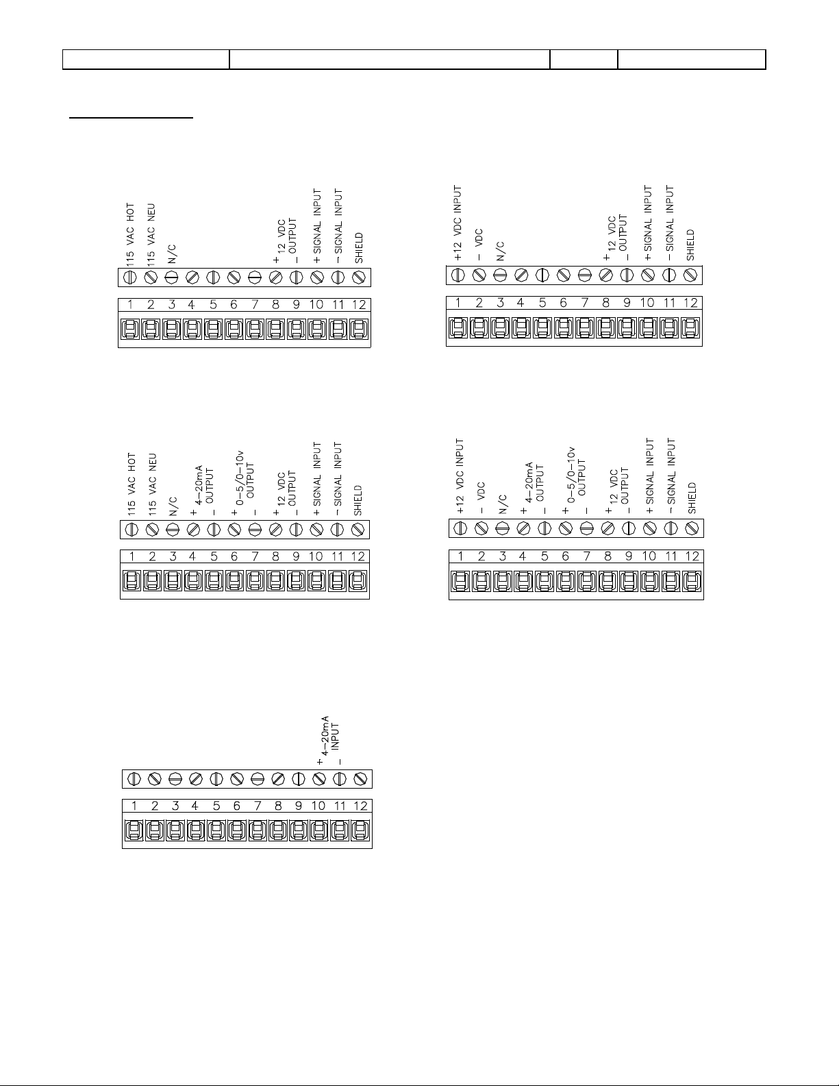
For 115VAC
For +12VDC
For 115VAC wit h A nalog Output
For +12VDC with A nalog Output
Field Terminations
MODEL AN25
MODEL AN25-L
DOC#: MN-AN25
Page 6

Sponsler Co., Inc. AN25 Totalizer/Rate Indicator
pg.
6
Engineering Units
K-Factor
F x T x C.F.
D
F x C.F. x 60
D
(Rate is per mi nute)
DOC#: MN-AN25
CALIBRATION
Sensitivity
The sensitivity adjust R6 is located on the Power Supply and Input Amplifier P.C.B. The amplitude of the signal
gen er ated by t he turbine is proport i onal to the rate of flow, therefore, sensitivit y should be adjusted at the lowest
usable flow rate. Rotate R6 co mpletely counter-clockwise, then slowly rotate R6 clockwise unti l the di splay correctly
responds, then increase R6 slightly clockwise.
Calibrati on Factor for Total & Rate
The calibration factor is d er ived from the turbines K-Factor (Pulses per gallon or other desired engineering unit ) .
The K-Factor i s listed on the calibration d ata sheet for the specific turbine being used .
C.F. =
Example # 1: K-Factor = 250 Pulses per gallon
Desired Engineering Units = gallons
C.F. = 1/250 = .00400
On the factoring P.C.B.
Set S6 #3 ‘ON’ (↓ Position) for ÷ 100 (Moves decimal point right 2 places)
Set S2 @ 4, S3, S4, S5 @ 0 (Enters .4000)
Set S1 in ‘0’ Position (0.4000)
The electronic accuracy can be verified by injecting a stable frequency @ TB1-10, 11 and
inco r poratin g the foll owing formulas:
Total =
Rate =
Where F = Frequency in Hz
T = Time (Duration) of test in seconds
C.F. = Calibration Factor as entered in S1-S5
D = Divisor as entered in S6
Example #2: F = 500 Hz T = 2 min (120 sec) C.F. = .4000 D = 100
Total = 500 x 120 x 4000
100
= 60,000 x 4000
100
= 24000/100 = 240 in 2 minutes
Rate = 500 x .4000 x 60
100
= 120 per minute
Page 7

Sponsler Co., Inc. AN25 Totalizer/Rate Indicator
pg.
7
Units p er Gallon
Pu l ses per G al lon
41, 381,600 x .1256
10
41, 381,600 x 1.2566
100
DOC#: MN-AN25
Calibration ‘0-1’ Function
The ‘0-1 ’ funct i on provid es enhanced accuracy when totalization encompasses a large quantity for an extended
period of time such as SCF produced in a 24 hour period.
The ‘0-1’ function should be incorporated only when both conditions listed below are met:
1) C.F.’s 1
2) C.F.’s 5
st
digit right of decimal is 1
th
digit right of decimal is n ot 0
Example #3 Assume a t urbine has a K -Factor of 79.58 pulses per SCF and the customer product demand is
520,000 SCF a day
C.F. = 1/79.58
= .0125659 = .12566 ÷ 10 Note: Both conditions are met
Without the ‘0-1’ function: S6 #2 ‘ON’ (÷ 10)
S2@1, S3@2, S4@5, S5@6
S1 in ‘0’ Position
A usage of 520,000 SCF = 41,381,600 total pulses (520,000 x 79.58) and using the C.F. of S1-
S6 the displayed quantity is 519,752 SCF ( ) rather than 520,000 for a
difference of 248 SCF.
With the ‘0-1’ function: Set S6 #2 ‘ON’ (↓ Position) for ÷ 100 (moves decimal right 2 places)
Set S2@2, S3@5, S4@6, S5@6 (.2566)
Set S1 in ‘1’ Position (1.2566)
as stated above the 24 hr usage is 520,000 SCF. The displayed quantity is now 520,001 SCF
( ) for a difference of 1 SCF.
Change of Calibr ation Engineeri ng Uni ts
Assume that liters rather than gallons is the desired engineering unit.
Example # 4 K-Factor = 250 pulses per gallon
Liters = 3.785 per gallon
C.F. = 3.785 / 250
C.F. = .01514 for display of liters
On the Factoring P.C.B.:
Set S6 #2 ‘ON’ (↓ Position) M oves decim al point r i ght 1 place
Set S2@1, S3@5, S4@1, S5@4 (.1514)
Set S1 in ‘0’ Position (0.1514)
Note: The ‘0-1’ functi on was not incorporated because onl y 1 of the 2 conditions was met
C.F.’s 1
C.F.’s 5
C.F. =
st
digit right of decimal is 1
th
digit right of decimal is 0
Page 8

Sponsler Co., Inc. AN25 Totalizer/Rate Indicator
pg.
8
Actual Quantity
Displayed Quant ity
DOC#: MN-AN25
Example #5: The Engineering Unit is pounds in 10
th
s CO2
K-Factor = 250 pulses per gallon
Pounds of CO
In or der to establish 10
= 8.470 per gallon
2
th
s, increase lbs./gal. by a factor of 10
C.F. = 84.7/250
C.F. = .3388
On the Factoring P.C.B.:
Set S6 #1 ‘ON’ (↓ Position) ÷ 1 does not move d ecimal poin t
Set S2@3, S3@3, S4@8, S5@8
Set S1 in ‘0’ Position
If the gallons per unit volume such as 7.48 gallons per FT
3
is known, but not the unit volume per gallon as
required to calculate the calibration factor; take th e r eciprocal of gallons per un it volum e to derive the unit
volume per gal l on.
7.48 gallons per FT
Example #6: The engineering unit is ACF (FT
3
1/7.48 = .13369 FT3 per gallon
3
)
K-Factor = 250 pulses per gallon
ACF = .13369 per gallon
C.F. = .13369 / 250
C.F. - .0005348
On the Factoring P.C.B.:
Set S6 #4 ‘ON’ (↓ Position) M oves decim al point r i ght 3 places
Set S2@5, S3@3, S4@4, S5@8
Set S1 in ‘0’ Position
Example #7: Desired Eng ineering Unit is ACF x 10
K-Factor = 250 pulses per gallon
ACF = .13369 per gallon
In or der to establish x 10, decrease A CF/gal by a factor of 10
C.F. = .013369 / 250 = .00005348
On the factoring P.C.B.:
Set S6 #5 ‘ON’ (↓ Position) M oves decim al point r i ght 4 places
Set S2@5, S3@3, S4@4, S5@8 (.5348)
Set S1 in ‘0’ Position (0.5348)
Field Corre ction of Calibration Factor
To adjust th e calibrat i on factor t o r efl ect the turbine’s actual response t o the operating conditions, incorp or ate the
following formula:
New C.F =
x Present C.F.
Page 9

Sponsler Co., Inc. AN25 Totalizer/Rate Indicator
pg.
9
DOC#: MN-AN25
Example #8: Actual = 50
Displayed = 52
C.F. = .4000
New C.F. = 50/52 x .4000
= .9615 x .4000
= .3846
On the factoring P.C.B.:
Set S2@3, S3@8, S4@4, S5@6
In the above example, .96 denotes that the meter is operating 4% fast. Multiplying by the present C.F.
(.4000) by the Displayed:Actu al Ratio (.96) effectively reduces the error by decreasing the C.F. by 4%.
Example #9: Actual = 52
Displayed = 50
C.F. = .4000
New C.F. = 52/50 x .4000
= 1.04 x .4000
= .4160
On the Factoring P.C.B.:
Set S2@4, S3@1, S4@6, S5@0
In the above example, 1.04 denotes that the meter is operating 4% slow. Multiplying the present C.F.
(.4000) by the Displayed:Actual Ratio (1.04) effectively reduces the error by increasing the C.F. 4%.
Rate Display Conside r ations
The displayed rate is limited to a maximum of 30,000. This characteristic must be considered when determining
the displayed engineering unit. Note that if the desired rate displayed is other than ‘Per Minute’, the calibration
factor is only correct for the rate displayed.
Example #10: A 1 ” turbi ne meter has a maximum fl ow rat e of 60 GPM and a K-Factor of 970 pulses per gallon in
Liquid Oxygen. The desired engineering unit is SCFH.
Given: 1 gallon O
= 115 SCF
2
1) Determine maximum flow rate; does it exce ed 30,000?
60 GPM x 115 SCF = 6900 SCFM
6900 SCFM x 60 = 414,000 SCFH
414,000 exceeds 30,000. Therefore, direct SCFH units are not permissible and some factor of
SCFH must be determined.
2) Determine what factor of SCFH is permissible –
4140 is the largest SCFH factor under 30,000; 1/100 of the actual SCFH flow rate.
3) Determine the cal i bration factor for SCFH x 100 K-Factor = 9 70 Pulses per gallon
SCF O
= 115 per gallon
2
A) I n order t o establish x 10 0 decrease SCF/G al by a factor of 1 00 (115/100 = 1.15)
B) In order to establish per hour increase SCF/Gal by a factor of 60 (1.15 x 60 = 69)
C.F. = 69/970
= .07113
On the Factoring P.C.B.:
Set S6 #2 ‘ON’ (↓ Position) for ÷ 10 (moves decimal point right 1 place)
Set S2@7, S3@1, S4@1, S5@3 (.7113)
Set S1 in ‘0’ Position (.07113)
Page 10

Sponsler Co., Inc. AN25 Totalizer/Rate Indicator
pg.
10
DOC#: MN-AN25
Page 11

Sponsler Co., Inc. AN25 Totalizer/Rate Indicator
pg.
11
DOC#: MN-AN25
Page 12

Sponsler Co., Inc. AN25 Totalizer/Rate Indicator
pg.
12
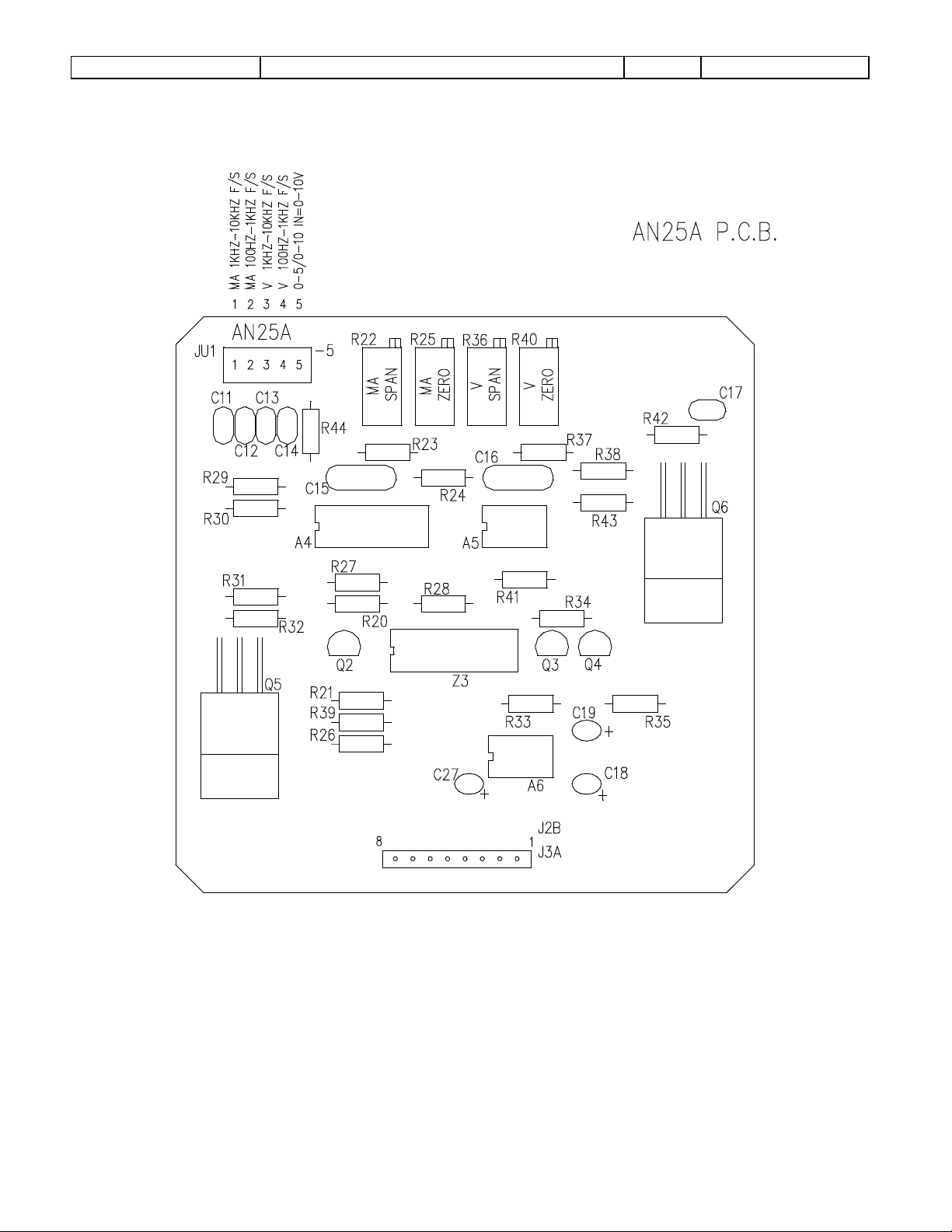
Calibration of Analog Outputs
DOC#: MN-AN25
REQUIRE D EQUIPMENT: Power Supply 110 VAC or 12-16.5 VDC
2 Digital Mu ltimeters (DMM)
Frequency Generator
Frequency Counter
NOTE: All test eq uipment power cords should be equipped with 2 prong “cheater” plugs.
a) Connect power supply Positive (HOT) & Negative (NEU) leads to TB1-1 ,2 respectively.
b) Connect #1 DMM Positive lead TB1-4. Connect #1 DMM Negative lead to 250 Ω resistor; Conn ect other end
of resistor to TB1-5. Set DMM function to mA DC.
c) Connect #2 DMM Positive & Negative leads t o TB1-6, 7 respectively. Set DMM function t o Volts DC .
d) Connect frequency generator P ositive & Negative leads to TB1-1 0, 11 respectively. Set output to si newave
and amplitude to zero.
e) Set “Sensitivity” adjust R1 fully clockwise
f) Install jumpers at JU1 or JU2 and JU3 or JU4 for desired frequency range.
g) Select desired voltage output level. Install JU5 for 0-10V; omit for 0-5V.
h) Turn Power Supply & Frequency Generator “ON”
i) Adjust “ZERO” (R25) for 4.00mA #1 DMM indication.
j) Adjust “ZERO” (R40) for .000VDC #2 DMM indication.
k) Adjust signal amplitude of frequency generator to 50mV & frequency to maximum desired point (full scale
frequency)
l) Adjust “SPAN” (R22) for 20.00mA #1 DMM indication.
m) Adjust “SPAN” (R36) for 5.00V or 10.00VDC #2 DMM indication.
n) Reduce signal amplitude of frequency generator to zero. Adjust “ZERO” (R25) for 4.00mA #1 DMM indication,
if necessary. Adjust “ZERO” (R40) for .000VDC #2 DMM indication, if necessary.
o) Adjust signal amplitude of frequency generator to 50mV. Adjust “SPAN” (R22) for 20.00mA #1 DMM
indication, if necessary. Adjust “SPAN” (R36) for 5.00V or 10.00VDC #2 DMM indication, if necessary.
p) Ad j ust frequency of freq uency g enerator to exactly 50% of maximum frequency point in step K. #1 DMM
should indicate 12.00mA +/- .06mA; #2 DMM should indicate 2.50V or 5.00V +/- .02V.
To check for linearity @ any frequency point:
Volt age output:
F/F Max X Full Scale Output = Volts
Example: Assume maximum frequency point = 2KHz & full scale output = 10v. Check for linearity
@ 750Hz point
750/2000 X 10 = 3.75V #1 DMM should indicate 3.75V +/- .03V
mA output:
(F/F Max X 16) + 4 = mA
Example: Assume maximum frequency point = 2KHz
Check for linearity @ 750Hz point
(750/2000 X16) + 4 = mA
(.375 X 16) + 4 = mA
6 + 4 = 10mA #1 should indicate 10.00mA +/- .06
Page 13
Sponsler Co., Inc. AN25 Totalizer/Rate Indicator
pg.
13
DOC#: MN-AN25
Page 14

Sponsler Co., Inc. AN25 Totalizer/Rate Indicator
pg.
14
AN25: ¼” DIN Dim ensional Information
DOC#: MN-AN25
Page 15

Sponsler Co., Inc. AN25 Totalizer/Rate Indicator
pg.
15
DOC#: MN-AN25
Page 16

© 2009
Pub. No. MN-AN25-mA
(9/2009)
 Loading...