

Page 1

Optical Air Eliminator (US Patent #7000628)
Rened Fuels Applications (A8981 & A8981A)
Installation
and Parts
Liquid ControLs Group
An IDEX Fluid & Metering Business
Installation: M300-20
Page 2

Table of Contents
Introduction
Specications ................................................. 3
General Information ....................................... 3
How Optical Air Eliminators Work .................. 4
Installation
New Installations ............................................ 6
Retrot Installations ....................................... 6
Dimensional Drawing ..................................... 8
Wiring ............................................................. 9
Maintenance
Disassembly ..................................................11
Reassembly ................................................. 13
Troubleshooting ........................................... 14
Bill of Materials
Exploded View ............................................. 15
Bill of Materials ............................................. 15
! WARNING
• Before using this product, read and understand the instructions.
• Save these instructions for future reference.
• All work must be performed by qualied personnel trained in the proper application, installation, and maintenance
of equipment and/or systems in accordance with all applicable codes and ordinances.
• Failure to follow the instructions set forth in this publication could result in property damage, personal injury, or death
from re and/or explosion, or other hazards that may be associated with this type of equipment.
Publication Updates and Translations
The most current English versions of all Liquid Controls publications are available on our web site, www.lcmeter.com. It
is the responsibility of the local distributor to provide the most current version of LC manuals, instructions, and specication sheets in the required language of the country, or the language of the end user to which the products are shipping . If
there are questions about the language of any LC manuals, instructions, or specication sheets, please contact your local
distributor.
2
Page 3

Optical Air Eliminators (A8981 & A8981A)
Specications
Environmental Rating
NEMA 4X
Safety
Designed to meet Class I, Division 2 requirements
Materials of Construction
Class1
Body: Aluminum
Solenoid: Brass
Class2
Body: Anodized Aluminum
Solenoid: Stainless Steel
Pressure Rating
Maximum non-shock working pressure
• 150PSI (10.3BAR)
Maximum differential pressure
• 100PSI (6.9BAR)
Temperature Rating
-40° to 160°F (-40° to 71°C)
Products
Class1 Rened Fuels
Gasoline, Gasohol, Diesel fuel, and Fuel Oil
Class2Aviation
Av-Gas and Jet Fuel
Solenoid (S3)
Voltage: +12 (± 2)VDC
Optional: +24 (± 4)VDC
Current: 1A maximum
Optical Sensor
Voltage: +10 to +28VDC
Current: 0.5A maximum
General Information
The Liquid Controls Optical Air Eliminator is designed for
use with LectroCount® Electronic Registers. An optical
sensor, installed in the wall of the air eliminator housing,
is used to monitor the liquid level. The presence or absence of liquid at the sensor level activates or deactivates
a solenoid valve located at the top of the air eliminator to
vent air or vapor from the system.
The optical air eliminator is designed to work with Liquid
Controls M5, M7, M10, M15, and M25 meters, for applications measuring rened petroleum products. Designed
with the same mounting dimensions as Liquid Controls
mechanical air eliminators, the optical air eliminator does
not require plumbing changes to retrot to existing meter
installations; however, electronic registers do require CPU
board part number 81920 for LCR and LCR-II; CPU board
part number 81924 for LC³. The optical air eliminator also
requires the use of a solenoid-operated control valve such
as the E-7 or A2848-11 on the outlet side of the meter.
Class 2
The Liquid Controls Optical Air Eliminator can be manufactured for Class 2 aviation applications. The Class 2 optical
air eliminator (Part #A8981A) is made with an anodized
aluminum housing and a stainless steel solenoid valve.
3
Page 4

Introduction
Solenoid Valve - OPEN
Vent
Optical Sensor
Control Valve - OPEN
Liquid Level
Solenoid Valve - OPEN
Vent
Optical Sensor
Control Valve - CLOSED
Liquid Level
How the Optical Air Eliminator Works
A solenoid valve, located at the top of the air eliminator,
is either open or closed. When the liquid level is below
the optical sensor (Figure 1), and a delivery is initiated,
the solenoid valve opens and vents air and vapor to
atmospheric pressure. At the same time, a solenoid-actuated control valve (A2982-11 or A2848-11) closes at the
meter outlet.
When liquid rises to the optical sensor level as the air is
exhausted (Figure 2), the optical air eliminator solenoid
valve closes and prevents continued venting to atmospheric pressure. At the same instant, the control valve
at the meter outlet opens so that a delivery may begin or
continue. This functionality ensures that only liquid passes
through the meter for measurement.
As long as a delivery is active and the liquid level remains
at or above the optical sensor, the optical air eliminator
solenoid valve remains closed and the control valve remains open. If the liquid level should drop below the optical
sensor, the optical air eliminator solenoid valve opens and
the control valve closes. When the delivery is complete,
the control valve closes and the printer prints a delivery
ticket. The optical air eliminator solenoid valve is not active between deliveries and remains OFF or closed.
Figure 1: Liquid Level below Optical Sensor
Figure 2: Liquid Level at or above Optical Sensor
4
Page 5

Introduction
How the Optical Air Eliminator Works
The gures to the left show a cutaway view of the vent port
through the solenoid valve. This port has been designed
to optimize the venting of air and vapor from the optical
air eliminator.
When the liquid level is below the sensor, the S3 solenoid
valve is open and allows air and vapor to vent through the
solenoid valve as shown in Figure 4. When the liquid level
is at or above the optical sensor, the S3 solenoid valve
closes the vent path as shown in Figure 5.
Figure 4: Solenoid and Port Open
Figure 5: Solenoid and Port Closed
The diagram in Figure 6 shows the LectroCount register
logic for a preset delivery. In order to function properly, the
optical air eliminator must be used in conjunction with a
solenoid-actuated control valve at the meter outlet, such
as the A2982-11 or A2848-11.
Figure 6: Optical Air Eliminator operating sequence.
5
Page 6
Installation
½" NPT Port
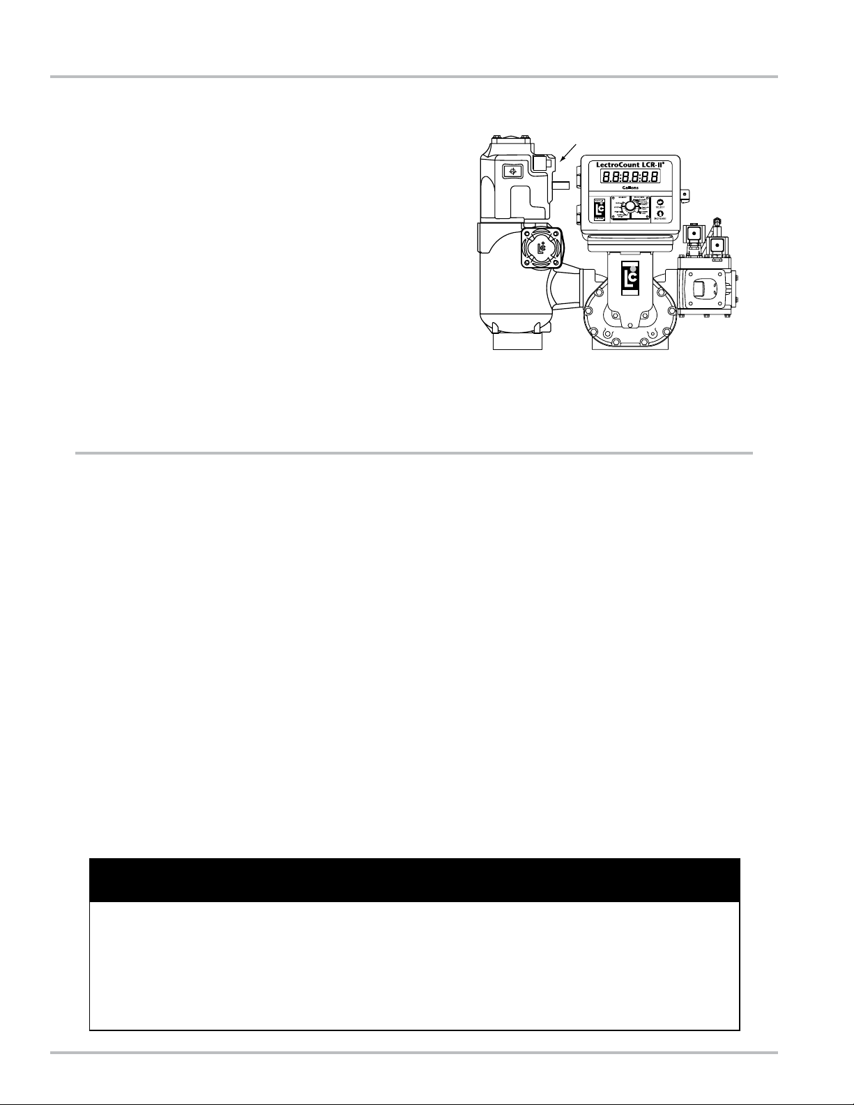
New Installations
When ordered with a new meter, the optical air eliminator is supplied mounted atop a strainer on the inlet side
of the meter. An example is the meter with high-capacity
strainer, two-stage valve, and LectroCount LCR-II® Electronic Register shown in the gure to the right.
A vent line must be connected from the output port of the
optical air eliminator. This connection is ½” NPT. The vent
line must be connected to an appropriate receptacle such
as an overow tank on a truck.
The optical air eliminator solenoid valve and optical sensor are supplied pre-wired to the LectroCount Electronic
Register.
Figure 7: New Assembly
Retrot Installations
Depending on the existing conguration, adding an optical
air eliminator valve may require modication of the vent
piping, modication or change of the outlet valve, and
modication or change of the register.
The optical air eliminator requires the following components to operate:
• LectroCount LCR/LCR-II Electronic Register with
internal CPU board Part Number 81920 or LC³ with
CPU board Part Number 81924.
• Electronically-controlled outlet valve such as the
A2982-11 or A2848-11.
Refer to the manuals accompanying these items for proper
installation and conguration.
! WARNING
Before disassembly of any meter or accessory component, ALL INTERNAL PRESSURES MUST BE RELIEVED
AND ALL LIQUID DRAINED FROM THE SYSTEM IN ACCORDANCE WITH ALL APPLICABLE PROCEDURES.
Pressure must be 0 (zero) psi. Close all liquid and vapor lines between the meter and liquid source.
Failure to follow this warning could result in property damage, personal injury, or death from re and/or explosion, or
other hazards that may be associated with this type of equipment.
6
Page 7
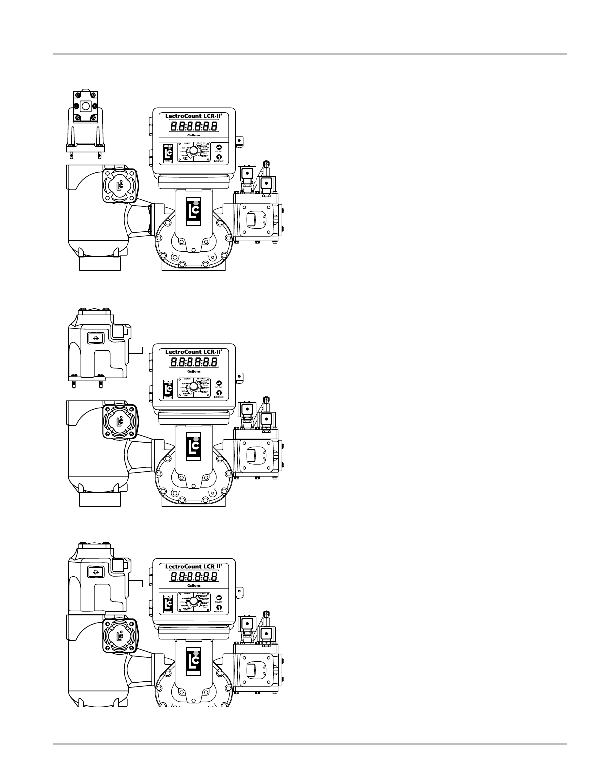
Figure 8: Remove old Air Eliminator
Installation
Retrot Installations
These retrot instructions will show a system using a
Hi-Cap strainer/air eliminator; however, the optical air
eliminator may also be installed on other LC strainer assemblies used for rened petroleum products.
Step 1 - Remove Old Air Eliminator and Baffel Cup
After the internal pressure has been relieved from the system
and the assembly drained of liquid, remove the four bolts
and washers used to fasten the old air eliminator to the top
of the strainer. Inspect the O-ring and replace if necessary.
Step 2 - Mount the Optical Air Eliminator
Depending on the strainer being used, the optical air eliminator may be fastened to the strainer/air eliminator in any of four
90° rotational increments. Select the most suitable orientation
for ease of nal installation of wiring and vent piping.
Figure 9: Orient the Optical Air Eliminator
Fasten the optical air eliminator to the strainer using the
four bolts and washers. Tighten the bolts to a torque of 27
lbf-ft (37 Nm).
Step 3 - Connect the Vent Piping/Tubing
This connection is ½” NPT. Remove the pipe thread protector
and then connect the piping/tubing to the vent port. This piping typically connects directly to an overow tank on a truck.
Step 4 - Wire the Solenoid and Sensor to the Register
Wiring instructions begin on Page 9.
Figure 10: Fasten the Optical Air Eliminator
7
Page 8
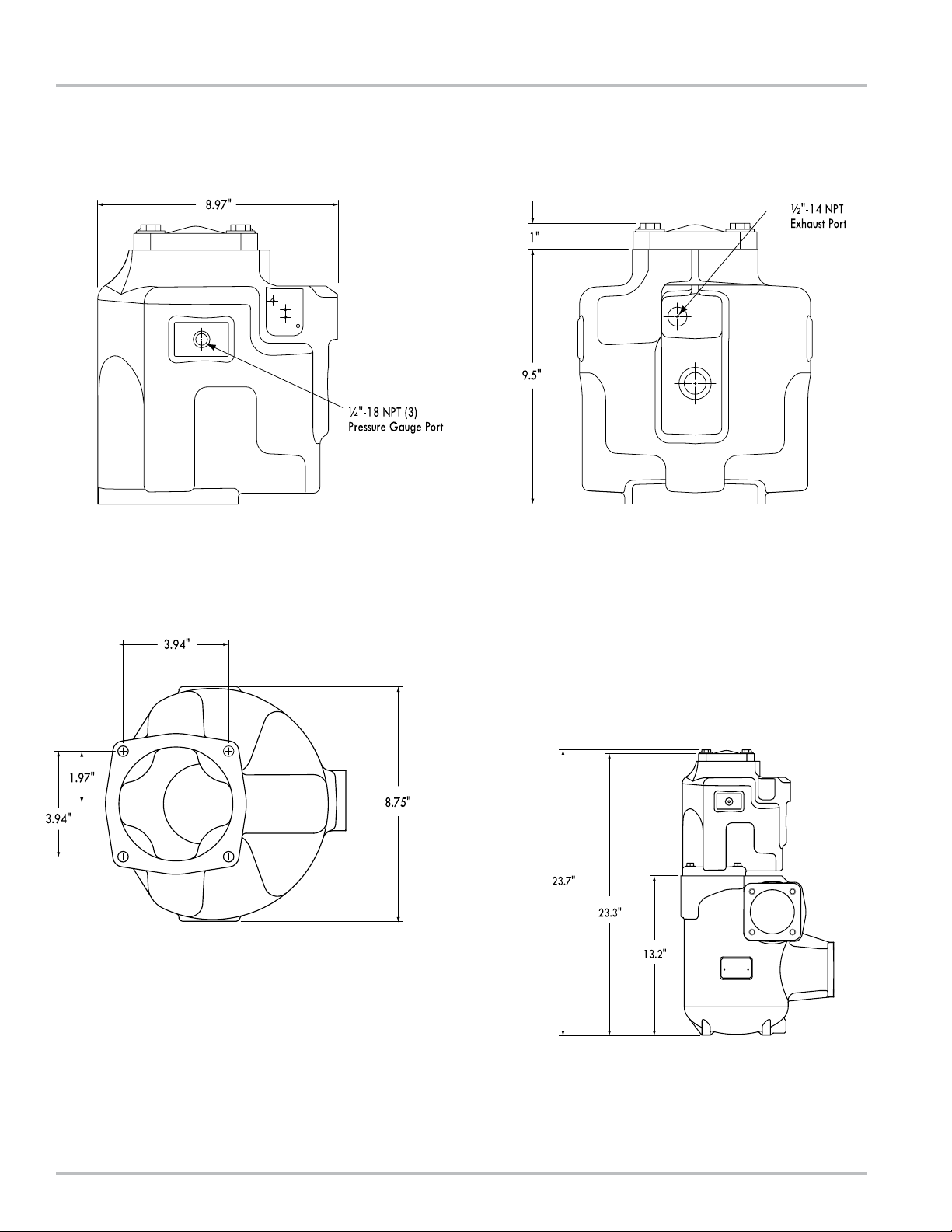
Dimensions
Front Side
Bottom
optical air eliminator with
igh capacity Strainer
h
Dimensionsshownarenotforconstructionuse.
ConsultfactorywhencertiedEngineeringDrawingsarerequired.
8
Page 9

Installation
Wiring
The optical air eliminator requires a LectroCount LCR/
LCR-II Electronic Register with CPU board part number
81920 (LC³ with 81924). If the LectroCount does not
contain an 81920 CPU board (LC³ with 81924), this board
must be ordered as a replacement to the existing CPU
board.
The 81920 CPU board has an additional connector, connector J15, not present on other board models. On the
LC³ 81924 CPU board it is connector J11.
To make the connection to a LectroCount Register, the
optical sensor comes supplied with a 24” cable. The cable
is potted in the optical sensor assembly at one end. A
threaded cord grip is included to fasten the other end of
the cable into the back of the LectroCount Register. The
solenoid requires a 12 AWG, two-wire, braided cable,
approximately 24 to 36” in length.
Step 1 - Remove Cable Plug
Loosen and remove the screw from the cover of the S3
solenoid valve cable plug. Remove the cable plug from the
solenoid valve coil. Remove the cover from the cable plug
housing and then remove the terminal block. Be sure to note
its orientation in the housing. Leave the at gasket in place
on the coil.
Step 2 - Connect Cable to Cable Plug
Route one end of the cable through the conduit tting and
into the cable plug housing. Connect the cable wires to the
terminal block. Connect the BLACK wire to Terminal 2 and
the RED wire to Terminal 1. These indicators are marked on
the terminal block.
! Caution
Incorrect wiring can damage the optical sensor.
! WARNING
For North American Installations, the installation must be fully in accordance with the National Electrical Code (US) or the Canadian Electrical Code respectively to maintain the hazardous location
ratings on the product. This may involve using rigid conduit for all connections.
9
Page 10

Installation
Wiring
Step 3 - Reassemble Cable Plug
Reinstall the terminal block into the cable plug housing in
the same orientation you found it. Tighten the strain relief
strap inside the cable plug using the two screws. Tighten the
cable gland on the bottom of the cable plug so that it seals
around the cable.
Reconnect the cable plug to the coil. Place the cover over
the cable plug and fasten with the screw to a torque of 8.8
in-lbs (1 Nm).
Step 4 - Connect to LectroCount Electronic Register
Route the cables from the optical sensor and solenoid valve
to the back of the LectroCount register. Connect these to two
open ports on the back of the register using the appropriate
connectors.
ConnectthewirestoterminalblockJ15ontheLectro-
LCR-II
CountCPUboard.RefertoFigure11aforadditional
clarication.
LCR-II Connections
Optical Sensor Connection
Wire Color J15 Pin Connection
Red 56
White 55
Black 54
S3 Solenoid Connection
Terminal J15 Pin Connection
1 (Red) 52
2 (Black) 53
LC³
ConnectthewirestoterminalblockJ11ontheLec-
troCountCPUboard.RefertoFigure11bforadditional
clarication.
LC3 Connections
Optical Sensor Connection
Wire Color J11 Pin Connection
Red 33
White 34
Black 35
S3 Solenoid Connection
Terminal J11 Pin Connection
1 (Red) 31
2 (Black) 32
Figure 11a: LCR-II to Optical Air Eliminator Wiring
Figure 11b: LC³ to Optical Air Eliminator Wiring
10
Page 11
Maintenance
! WARNING
Before disassembly of any meter or accessory component, ALL INTERNAL PRESSURES MUST BE RELIEVED
AND ALL LIQUID DRAINED FROM THE SYSTEM IN ACCORDANCE WITH ALL APPLICABLE PROCEDURES.
Pressure must be 0 (zero) psi. Close all liquid and vapor lines between the meter and liquid source.
Failure to follow this warning could result in property damage, personal injury, or death from re and/or explosion, or
other hazards that may be associated with this type of equipment.
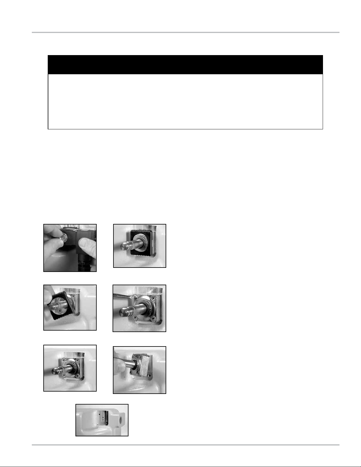
Disassembling
Tools required:
• Flat blade screwdriver
• 14mm box end or open end wrench
The optical air eliminator consists of a housing, optical
sensor, and control solenoid valve. Of these three components, only the solenoid valve is serviceable; however,
if any part of the solenoid is damaged, a new solenoid
assembly (Part Number 502011) must be ordered. The
optical sensor contains no serviceable parts because the
internal components are potted. If the optical sensor fails,
the complete assembly must be replaced (Part Number
81947).
Step 1
Loosen the thin hex nut holding the solenoid in place using a
14mm wrench. Remove the nut and coil off of the armature
guide post.
Step 2
Remove the plastic bonnet from the armature guide post.
This should be easy to remove without tools.
Step 3
Using a screwdriver, loosen the upper left and lower right
screws of the valve body. These are the only two screws
which hold the valve body in place. The upper right and
lower left screws fasten the armature guide post and valve
body together. Remove the valve body from the optical air
eliminator housing.
11
Page 12

Maintenance
Disassembling
Step 4
Place the valve body on a at surface. Using a at blade
screwdriver, remove the two screws which hold the armature
guide post and valve body together. Lift the armature guide
post off of the valve body. The internal components consist
of a plunger and a spring. Inspect the spring for damage.
Step 5
The armature guide post is composed of four components:
two O-rings, the guide post, and the ange. Inspect these
components for damage.
Step 6
The valve body has two O-rings found on the face which
faces the housing. These two O-rings are identical. Inspect
these for damage. Inspect the ports for blockage.
O-rings
O-rings
12
Page 13

Maintenance
Reassembling
Step 1
Place the spring inside the plunger and insert the plunger,
spring end rst, into the armature guide post. Place the armature guide post assembly on the valve body.
Fasten the armature guide post to the valve body using the
two screws removed earlier. Two holes of the valve body are
threaded and two are not. Make sure the screws are being
inserted into the threaded holes.
Note that the valve body has a number stamped into it. This
will be used to set the proper orientation of the solenoid
valve body with respect to the optical air eliminator housing
assembly.
Number Stamp
Position solenoid valve body
with number stamp in this
location
Step 2
Align the solenoid valve body so that the stamped number on
the valve body faces the housing assembly as shown in the
picture to the left. The valve body can physically be fastened
to the housing assembly in one of two orientations. Only one
orientation is correct.
IMPORTANT!
Ifthestampednumbersfaceawayfromthehousing,
theopticalaireliminatorwillnotfunctionproperly.The
portwillbeblockedandtheaireliminatorwillfail.
With the valve body in the proper orientation, fasten it to the
housing using the two screws removed earlier. Tighten to a
torque of 15 to 18 in-lbs (1.7 to 2.0 Nm).
13
Step 3
Place the plastic bonnet over the valve body and snap in
place.
Step 4
Place the coil over the armature guide post and fasten with
the thin hex nut. Tighten the nut with a 14mm wrench to a
torque of 4.5 in-lbs (0.5 Nm).
Page 14
Maintenance
! WARNING
Before disassembly of any meter or accessory component, ALL INTERNAL PRESSURES MUST BE RELIEVED
AND ALL LIQUID DRAINED FROM THE SYSTEM IN ACCORDANCE WITH ALL APPLICABLE PROCEDURES.
Pressure must be 0 (zero) psi. Close all liquid and vapor lines between the meter and liquid source.
Failure to follow this warning could result in property damage, personal injury, or death from re and/or explosion, or
other hazards that may be associated with this type of equipment.
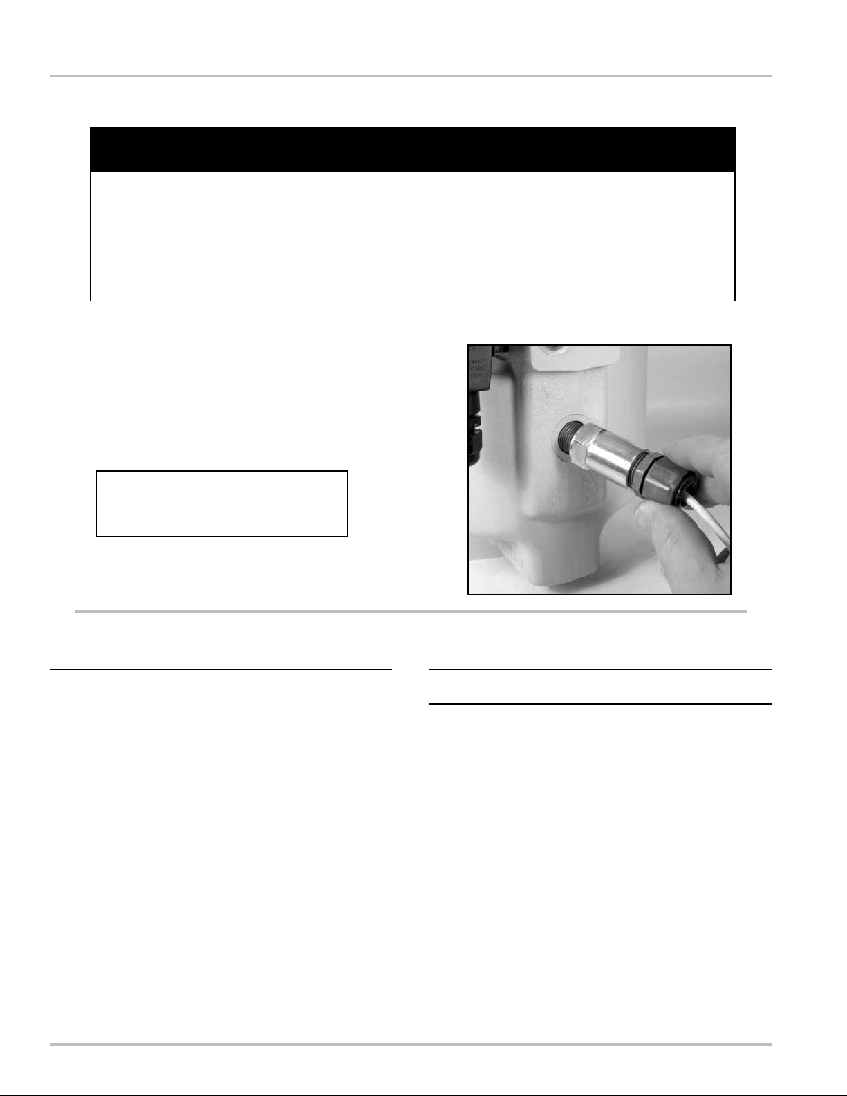
Optical Sensor
If the optical sensor ever needs replacement, use a 1”
open end wrench to remove the optical sensor from the
housing. When installing a new optical sensor, care should
be taken not to exceed a torque of 75 in-lbs (8.5 Nm).
Excessive torque may damage the sensor.
Alightcoatingofgreaseoranti-seize
lubricantshouldbeappliedtothethreads
ofthesensorpriortoassembly.
Troubleshooting
PROBLEM
Excessiveliquidowingoutofventtospittank.
Scenario 1: Solenoid not closing.
• Check S3 solenoid wiring.
• Measure resistance across S3 solenoid. Value should
read approximately 15 ω. If not, replace S3 solenoid.
• Inspect S3 solenoid for blockage. Refer to disassembly instructions.
• LectroCount CPU failure. Replace CPU board.
Scenario 2: Optical Sensor not functioning.
• Check optical sensor wiring.
• Measure resistance between the RED and WHITE
wires. Value should be approximately 10kω. If not,
replace optical sensor.
• LectroCount CPU failure. Replace CPU board.
PROBLEM
Noliquidowingthroughmeterduringdelivery.
Scenario 1: Liquid level not rising in optical air eliminator.
• Check S3 solenoid. It may not be opening to allow
air/vapor to vent.
• Check S3 solenoid wiring.
• Measure resistance across S3 solenoid. Value should
read approximately 15 ω. If not, replace S3 solenoid.
• Inspect S3 solenoid for blockage. Refer to disassembly instructions.
• LectroCount CPU failure. Replace CPU board.
Scenario 2: Meter outlet valve not opening
• Check wiring of the outlet valve S1 solenoid.
• Measure resistance across S1 solenoid. Value
should read approximately 15ω. If not, replace S1
solenoid.
• Inspect S1 solenoid for blockage. Refer to the manual
which accompanies the valve.
• LectroCount CPU failure. Replace CPU board.
14
Page 15

Bill of Materials - Exploded View
Model Number: A8981 & A8981A
Italicized part numbers indicate A8981A (Class 2) parts. If there is no italicized number, the
listed part number applies to A8981 & A8981A
15
Page 16

Liqui d c onT roL S
105 Albrecht Drive
Lake Bluff, IL 60044
(847) 295-1050
Liqui d c onT roL S e uro pe/ SAm pi
Via Amerigo Vespucci 1
55011 Altopascio (Lucca), Italy
+39 0583 24751
ideX FLu id And me Ter ing pv T. LTd.
Survey No. 256, Alindra
Savli GIDC, Manjusar
Dist. Vadodara 391 770
Gujarat, India
+91 265 2631855
Liqui d c onT roL S S pon SLe r
105 Albrecht Drive
Lake Bluff, IL 60044
(847) 295-1050
TopTe ch SySTe mS
1124 Florida Central Parkway
Longwood, FL 32750
(407) 332-1774
Nateus Business Park
Nieuwe Weg 1-Haven 1053
B-2070 Zwijndrecht (Antwerp), Belguim
+32 (0)3 250 60 60
FAu re her mAn
Route de Bonnetable
B.P. 20154
72406 La Ferté-Bernard Cedex, France
+33 (0)2 43 60 28 60
6961 Brookhollow West Drive
Houston, TX 77040
(713) 623-0808
corke n
3805 Northwest 36th St.
Oklahoma City, OK 73112
(405) 946-5576
105 Albrecht Drive
Lake Bluff, IL 60044-2242
1.800.458.5262 • 847.295.1050
Fax: 847.295.1057
www.lcmeter.com
© 2008 Liquid Controls
Pub. No. 500333
(2/12)
 Loading...