

Page 1
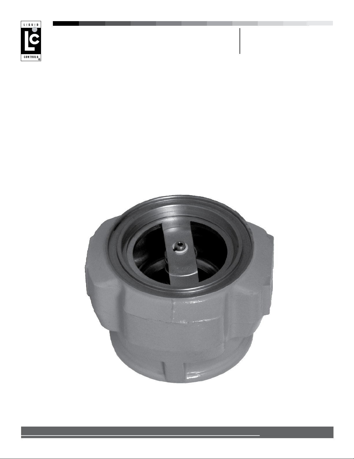
Back Check Valves
A2885 & A2883 (LPG)
A2882 (Rened Fuels)
Installation & Parts
Liquid ControLs Group
An IDEX Fluid & Metering Business
Installation: M400-50
Page 2
TABLE OF CONTENTS
INTRODUCTION
Safety Procedures ................................................... 2
General Information ................................................. 3
A2885 & A2883 (LPG)
New Installations ...................................................... 3
Retrot Installations and Maintenance .................... 4
Disassembly .....................................................................4
Reassembly .....................................................................4
A2882 (REFINED FUELS)
New Installations ...................................................... 5
Retrot Installations and Maintenance .................... 5
Disassembly .....................................................................5
Reassembly .....................................................................5
BILL OF MATERIALS
A2885 & A2883 (LPG) .............................................. 6
A2882 (Rened Fuels) ............................................. 7
Publication Updates and Translations
The most current English versions of all Liquid Controls publications are available on our web site, www.lcmeter.com. It is the
responsibility of the local distributor to provide the most current version of LC manuals, instructions, and specication sheets in
the required language of the country, or the language of the end user to which the products are shipping. If there are questions
about the language of any LC manuals, instructions, or specication sheets, please contact your local distributor.
Be Prepared
! WARNING
• Before using this product, read and understand the instructions.
• All work must be performed by qualied personnel trained in the proper application, installation, and maintenance
of equipment and/or systems in accordance with all applicable codes and ordinances.
• When handling electronic components and boards, always use proper Electrostatic Discharge (ESD) equipment
and follow the proper procedures
• Make sure that all necessary safety precautions have been taken.
• Provide for proper ventilation, temperature control, re prevention, evacuation, and re management.
• Provide easy access to the appropriate re extinguishers for your product.
• Consult with your local re department, state, and local codes to ensure adequate preparation.
• Read this manual as well as all the literature provided in your owner’s packet.
• Save these instructions for future reference.
• Failure to follow the instructions set forth in this publication could result in property damage, personal injury, or
death from re and/or explosion, or other hazards that may be associated with this type of equipment.
Safely Evacuate
Piping System
! WARNING
Before disassembly of any meter or accessory component:
ALL INTERNAL PRESSURES MUST BE RELIEVED AND ALL LIQUID DRAINED FROM
THE SYSTEM IN ACCORDANCE WITH ALL APPLICABLE PROCEDURES.
-Pressure must be 0 (zero) psi.
-Close all liquid and vapor lines between the meter and liquid source.
For Safety Rules Regarding LPG, refer to NFPA Pamphlet 58 and local authorities.
Failure to follow this warning could result in property damage, personal injury, or death from re and/or explosion, or other
hazards that may be associated with this type of equipment.
2
Page 3
INTRODUCTION / A2885 & A2883 (LPG)
Observe National and
Local Codes
Power, input, and output (I/O) wiring must be in accordance with the area classication for which it is used (Class I, Div 2).
For North America, installations must be per the U. S. National Electrical Code, NFPA 70, or the Canadian Electrical Code
in order to maintain Class I, Division 2 ratings. This may require using connections or other adaptations in accordance
with the requirements of the authority having jurisdiction.
WARNING: Explosion Hazard -
Substitution of components may impair suitability for Class I, Division 2 applications.
WARNING: Explosion Hazard -
When in hazardous locations, turn power OFF before replacing or wiring modules.
WARNING: Explosion Hazard -
Do NOT disconnect equipment unless power has been switched OFF or the area is known to be Non-Hazardous.
! WARNING
General Information
Liquid Controls soft seat Back Check Valves are designed to prevent reverse ow of product through the meter.
This assures that the meter and all components downstream remain full of the liquid being measured. The A2885
and A2883 for LPG are installed on the inlet side of the strainer assembly on the meter. The A2885 and A2883 are
applicable for MA-5 and MA-7 meters. The A2882 for Rened Petroleum products is installed on the outlet side of the
meter. The A2882 is applicable for M-5, M-7, and M-10 Meters.
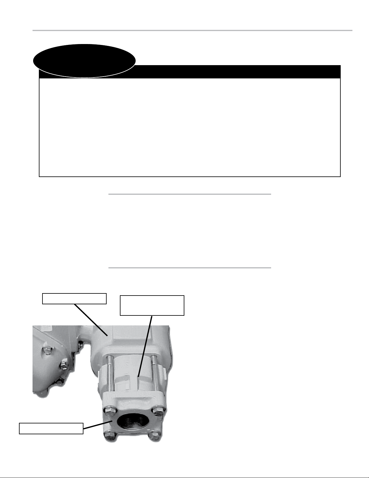
Strainer Assembly
A2885 or A2883
Back Check Valve
A2885 & A2883 Back Check Valves
NEW INSTALLATIONS
When ordered with a new metering system, the A2885
or A2883 Back Check Valve is supplied mounted to the
inlet side of the strainer housing as shown to the right.
To complete the A2885 or A2883 Back Check Valve
portion of the installation, a liquid line must be connected
to the ange on the inlet side of the valve. The ange
connection is 2” NPT.
2" NPT Flange (Inlet)
3
Page 4

A2885 & A2883 (LPG)
A2885 & A2883 Back Check Valves
RETROFIT INSTALLATIONS
Depending on the existing conguration, adding an
A2885 or A2883 Back Check Valve may require
modication of the inlet piping.
After the internal pressure is relieved from the system,
the inlet line can be disconnected from the inlet side of
the strainer assembly. The valve and ange assembly
can then be connected to the inlet side of the strainer.
Use the four bolts and washers provided to fasten the
valve/ange assembly to the strainer as shown on Page
3. Tighten the bolts in a crossing pattern as shown to the
right. Once the valve/ange assembly is secure, the inlet
line may be reconnected to the ange. The ange tting
is 2” NPT.
Item Numbers
Refer to the illustrated parts breakdown on Page 6 for Item Numbers referenced in these
instructions. Item Numbers appear in circles in the drawing.
Bolt Tightening Pattern
DISASSEMBLY
1. Remove the valve from the line by removing the four
screws (Item 3) and washers (Item 4) that hold it in place.
2. Using a tire valve stem changer, remove the relief valve
(Item 920) from the valve stem (Item 265).
3. From the inlet side of the valve, unscrew the valve stem
(Item 265) from the valve nut (Item 875).
4. Remove the valve nut (Item 875) by pressing down on
the spring holder (Item 382). The spring should be held
down with a press. Lift the valve nut out of position. The
spring holder and lock washer can now be removed from
the housing.
5. Remove the O-Ring retainer (Item 452), O-Ring (Item
470), piston (Item 133), O-Ring (Item 471), and spacer
(Item 472), lifting by the threaded end of the valve stem
(Item 265).
6. Remove the O-Ring retainer (Item 452) and O-Ring (Item
471) from the stem.
7. Remove the O-Ring (Item 471) and the piston (Item 133)
from the stem.
8. Replace components if necessary and reassemble. The
bushing (Item 485) is pressed in place and need not be
removed.
REASSEMBLY
1. Place the piston (Item 133) on the valve stem (Item 265),
with the raised rim pointing upwards.
2. Place the spacer (Item 472) and O-Ring (Item 471) on
the piston (Item 133)
3. Place the O-Ring (Item 470) on the retainer (Item 452)
and place it over the piston (Item 133) with the O-Ring
downward.
4. Place a self locking nut (Item 875) on the valve stem and
tighten. Place a second self locking nut (Item 875) on the
valve stem and tighten.
5. Insert this assembly into the housing (Item 110) from the
outlet side.
6. Place the compression spring (Item 595) over the valve
stem (Item 265).
7. Insert the Teon bearing (Item 486) into the valve spring
holder (Item 382).
8. Place the spring holder (Item 382) on the housing (Item
110) and compress the spring inward. A press should be
used to overcome the force of the spring.
9. Secure the spring holder with the spiral retaining ring
(Item 393).
10. Screw the pressure relief valve (Item 920) into the valve
stem (Item 265) using a tire valve stem changer.
11. Place the O-Ring (Item 473) in the groove on the outlet
side of the housing assembly (Item 110).
The back check valve is now ready to be reinstalled using the
four screws (Item 3) and washers (item 4).
4
Page 5

A2882 (REFINED FUELS)
Meter Outlet
2882 Back Check Valve
Item Numbers
Refer to the illustrated parts breakdown on Page 7 for Item
Numbers referenced in these instructions. Item Numbers appear
in circles in the drawing.
A2882 Back Check Valves
NEW INSTALLATIONS
When ordered with a new metering system, the A2882
Back Check Valve is supplied mounted to the outlet
side of the meter as shown to the right. To complete the
A2882 Back Check Valve portion of the installation, a
liquid line must be connected to the ange on the outlet
side of the valve. The ange connection is 2” NPT.
RETROFIT INSTALLATIONS
Depending on the existing conguration, adding an
A2882 Back Check Valve may require modication of the
outlet piping.
After the internal pressure is relieved from the
system (see warning on Page 2), the outlet line can
be disconnected from the output side of the meter
assembly. The valve and ange assembly can then be
connected to the outlet side of the meter.
Use the four bolts and washers provided to fasten the
valve/ange assembly to the meter. Tighten the bolts
in a crossing pattern (as shown on Page 4). Once the
valve/ange assembly is secure, the outlet line may be
reconnected to the ange. The ange tting is 2” NPT.
DISASSEMBLY
1. Remove the valve from the line by removing the four
screws (Item 3) and washers (Item 4) that hold it in place.
2. Using a tire valve stem changer, remove the relief valve
(Item 920) from the valve stem (Item 265).
3. From the inlet side of the valve, unscrew the valve stem
(Item 265) from the valve nut (Item 875).
4. Remove the valve nut (Item 875) by pressing down on
the spring holder (Item 382). The spring should be held
down with a press. Lift the valve nut out of position. The
spring holder and lock washer can now be removed from
the housing.
5. Remove the O-Ring retainer (Item 452), O-Ring (Item
470), piston (Item 133), O-Ring (Item 471) and spacer
(Item 472), lifting by the threaded end of the valve stem
(Item 265).
6. Remove the O-Ring retainer (Item 452) and O-Ring (Item
470) from the stem.
7. Remove the O-Ring (Item 471) and the piston (Item 133)
from the stem.
8. Replace components if necessary and reassemble. The
bushing (Item 485) is pressed in place and need not be
removed.
REASSEMBLY
1. Place the piston (Item 133) on the valve stem (Item 265),
with the raised rim pointing upwards.
2. Place the spacer (Item 472) and O-Ring (Item 471) on
the piston (Item 133)
3. Place the O-Ring (Item 470) on the retainer (Item 452)
and place it over the piston (Item 133) with the O-Ring
downward.
4. Place washer (705) over the valve stem and secure it
with self locking nut (875)
5. Insert this assembly into the housing (Item 110) from the
outlet side.
6. Place the compression spring (Item 595) over the valve
stem (Item 265).
7. Insert the Teon bearing (Item 486) into the valve spring
holder (Item 382).
8. Place the spring holder (Item 382) on the housing (Item
110) and compress the spring inward. A press should be
used to overcome the force of the spring.
9. Secure the spring holder with the spiral retaining ring
(Item 393).
10. Screw the pressure relief valve (Item 920) into the valve
stem (Item 265) using a tire valve stem changer.
The back check valve is now ready to be reinstalled using the
four screws (Item 3) and washers (item 4).
5
Page 6

BILL OF MATERIALS - A2885 & A2883 (LPG)
Model A2885 (For LPG)
Used on meters sold AFTER December 19, 1991 beginning
with Serial No. 225233
48863 2” Check Valve Assembly
Item Description Part Number
486 Bearing N/S*
473 Buna-N O-Ring 06854
393 Spiral Retaining Spring 09137
382 Valve Spring Holder 48337
595 Compression Spring 09138
875 Self Locking Nut (2) 09143
452 O-Ring Retainer 47974
470 Buna-N O-Ring 09131
471 Buna-N O-Ring 09140
472 Spacer 47295
133 Piston 47975
265 Valve Stem N/S
485 Bushing 07867
110 Check Valve Housing 47973
920 Valve Core N/S
N/S = Not for Sale
Model A2883 (For LPG)
Used on meters sold BEFORE December 19, 1991 ending with
Serial No. 225232
48190 2” Check Valve Assembly
Item Description Part Number
486 Bearing N/S
473 Buna-N O-Ring 06854
393 Spiral Retaining Spring 09137
382 Valve Spring Holder 48337
595 Compression Spring 09138
875 Self Locking Nut (2) 09143
452 O-Ring Retainer 47974
470 Buna-N O-Ring 09131
471 Buna-N O-Ring 09140
472 Spacer 47295
133 Piston 47975
265 Valve Stem N/S
485 Bushing 07867
110 Check Valve Housing 47994
920 Valve Core N/S
Mounting Screws & Bolts
(A2885 & A2883)
6
Page 7

BILL OF MATERIALS - A2882 (REFINED FUELS)
Model A2882 (For Rened Fuels)
48189 2” Check Valve Assembly
Item Description Part Number
393 Spiral Retaining Spring 09137
486 Bearing 07801
382 Valve Spring Holder 48337
595 Compression Spring N/S
875 Self Locking Nut (2) 09143
705 Flat Washer 40241
452 O-Ring Retainer 47974
470 Viton O-Ring 09025
471 Viton O-Ring 09139
472 Spacer 47295
133 Piston 47975
110 Check Valve Housing N/S
485 Bushing 07867
265 Valve Stem N/S
920 Valve Core N/S
420 Buna-N O-Ring 06854
Mounting Screws & Bolts
(A2882)
7
Page 8

Liquid conTroLS
105 Albrecht Drive
Lake Bluff, IL 60044
(847) 295-1050
Liquid conTroLS europe/SAmp i
Via Amerigo Vespucci 1
55011 Altopascio (Lucca), Italy
+39 0583 24751
Liquid conTroLS indiA
808 VCCI Complex
GIDC Makarpura
Vadodara-390 101
Gujarat, India
+91 265 2631855
Liquid conTroLS SponSLer
105 Albrecht Drive
Lake Bluff, IL 60044
(847) 295-1050
TopTech SyS Te mS
1124 Florida Central Parkway
Longwood, FL 32750
(407) 332-1774
Nateus Business Park
Nieuwe Weg 1-Haven 1053
B-2070 Zwijndrecht (Antwerp), Belguim
+32 (0)3 250 60 60
FAu re h er mA n
Route de Bonnetable
B.P. 20154
72406 La Ferté-Bernard Cedex, France
+33 (0)2 43 60 28 60
6961 Brookhollow West Drive
Houston, TX 77040
(713) 623-0808
corken
3805 Northwest 36th St.
Oklahoma City, OK 73112
(405) 946-5576
105 Albrecht Drive
Lake Bluff, IL 60044-2242
1.800.458.5262 • 847.295.1050
Fax: 847.295.1057
www.lcmeter.com
© 2004 Liquid Controls
Pub. No. 500320
(10/04)
 Loading...