

Page 1

LC-ON THE GOTM
Wireless WiFi Adapter
P/N 81538
Set-up and
Connection Guide
L I Q UID C O N T R O L S
An IDEX Energy & Fuels Business
LC_IOM_ONTHEGOWIFIADAPTER V1: 05/17
Page 2

PUBLICATION UPDATES AND TRANSLATIONS
The most current English versions of all Liquid
Controls publications are available on our web site,
www.lcmeter.com. It is the responsibility of the local
distributor to provide the most current version of LC
manuals, instructions, and specification sheets in the
required language of the country, or the language of the
end user to which the products are shipping. If there
are questions about the language of any LC manuals,
instructions, or specification sheets, please contact
your local distributor.
WARNING
Before using this product, read and
understand the instructions.
Save these instructions for future
reference.
All work must be performed by
qualified personnel trained in the
proper application, installation, and
maintenance of equipment and/
or systems in accordance with all
applicable codes and ordinances.
The documentation is only complete when used in
combination with the relevant documentation for the
wifi adapter.
All rights reserved. It is prohibited to reproduce this
documentation, or any part thereof, without the prior
written authorization of Liquid Controls, LLC.
Content is subject to change without notice.
www.LCmeter.com
05/2017 LC-ON THE GO
© Copyright 2017 by Liquid Controls, LLC.
TM
Wireless WiFi Adapter
Failure to follow the instructions
set forth in this publication could
result in property damage, personal
injury, or death from fire and/or
explosion, or other hazards that
may be associated with this type of
equipment.
2 WWW.LCMETER.COM
LC-ON THE GOTM Wireless WiFi Adapter
Page 3

TABLE OF CONTENTS
I. Basic Set Up ....................................................................................................4
II. Connecting to a Single Meter System ............................................................7
III. Connecting to an Existing Dual Meter System .............................................. 8
I V. Connecting to a New Dual Meter System .....................................................9
V. Connecting to EZ Command or EZ Command Lite .....................................12
LC-ON THE GOTM Wireless WiFi Adapter WWW.LCMETER.COM 3
Page 4

I. BASIC SETUP
Follow this Quick Start Guide to
get your unit up and running fast.
The LC-ON THE GOTM WiFi Adapter contains
the following items: wireless WiFi module and
antenna. It requires a lap-pad adapter 81514
(single meter systems) or multiplexer box
E25352 (dual meter systems.
Also required (sold separately):
Lap pad adapter (81514) for single meter system
1. Install antenna onto the Wireless WiFi
module.
2. Plug the DB9 connector into the lap pad
adapter or the RS-232 Lap Pad female
DB9 connection on the multiplexer.
The WiFi adapter will receive power through the lap
pad adapter or the multiplexer box. The green light
on the adapter will illuminate when power is applied
to the register.
3. Go to Settings or Wireless Network
Connections to find the wireless SSID on
your Apple or Android wireless device, or
laptop computer.
Search for available WiFi networks. With power to
the adapter, the wireless module will broadcast its
own unique SSID. The default SSID is XpicoWiFi_
xxxxxx, where xxxxxx are the last six characters of
the unique xPico Wi-Fi serial number on the back
of the adapter. For example, if the serial number on
the label is 0080A3AO7AA0, then the SSID would
be xPicoWiFi_AO7AA0. Click on the XpicoWiFi
SSID link to display the connect screen.
Note: The SSID can be customized by the user. (See
section 5. Entering the Liquid Controls Configuration
Mode.
OR
Multiplexer box (E25352) for dual meter system
4 WWW.LCMETER.COM
LC-ON THE GOTM Wireless WiFi Adapter
Page 5

4. Making the WiFi connection
The default security for the XpicoWiFi Soft AP is
WPA2.
The factory default password is the same for all WiFi
adapter devices.
5. Entering the Liquid Controls
Configuration Mode
Connect to the WiFi via local Windows™ PC or
Tablet.
Open a web browser and navigate to 192.168.0.1.
Password: onthegowifi
Note: the password can be changed via the configuration
interface (See section 5. Entering the Liquid Controls
Configuration Mode)
Enter default User Name and Password. (Note:
both are case sensitive).
User Name: admin
Password: PASSWORD
LC-ON THE GOTM Wireless WiFi Adapter WWW.LCMETER.COM 5
Page 6

I. BASIC SETUP
6. Default Key Configuration Settings
7. Changing the SSID:
Enter the Admin Screen and click on NETWORK,
“LINK” and “Configuration”
Click on the SSID and assign a new SSID.
Click to submit the new SSID. The unit will update
and disconnect. Re-establish the connection by
finding the new SSID and entering the passphrase.
8. Changing the Password:
Enter the Admin Screen and click on NETWORK,
“LINK” and “Configuration”
Click on Password and assign a new password.
Click to submit the new SSID. The unit will update
and disconnect. Re-establish the connection by
finding the new SSID and entering the passphrase.
6 WWW.LCMETER.COM
LC-ON THE GOTM Wireless WiFi Adapter
Page 7

II. CONNECTING TO A SINGLE METER SYSTEM
9. Setting Up A Single Meter System
A single meter system consists of a meter, an
electronic register and a printer. The ON THE GO
WiFi adapter may be used to communicate with
the register using Lap Pad adapter 81514. Connect
the Lap Pad adapter to the printer and data cable
(81513-series). Connect the ON THE GO WiFi
adapter to the lap pad adapter. The green power
light on the ON THE GO WiFi adapter will illuminate
when the system is powered. A separate power
supply is not required.
Note: The J10
jumper on
840405 board
must be in the B
position.
Lap pad adapter (81514) for single meter system
840405
LC-ON THE GOTM Wireless WiFi Adapter WWW.LCMETER.COM 7
Page 8

III. CONNECTING TO AN EXISTING DUAL METER SYSTEM
10. Setting up a Dual Meter System –
Existing System.
A dual meter system consists of 2 meters, 2
electronic registers, a multiplexer box and a printer.
a. Set the Internal Jumpers. Using a 5/64” Allen
wrench, remove the 8 black socket head screws
and remove the cover of the multiplexer box.
b. Locate JP5 and move the jumper from the CTS
position to the 12V position.
c. Replace the cover on the multiplexer box.
d. Connect the ON THE GO WiFi adapter to the
RS-232 LAP PAD female DB-9 connection on
the front of the multiplexer box.
e. The green power light on the ON THE GO
WiFi adapter will illuminate when the system
is powered. A separate power supply is not
required.
Move jumper to B position
for ON THE GO WiFi
f. Verify the position of the J10 jumper on the
840405 board inside the LCR-II or LCR600. The
J10 jumper must be in the B position.
840405
8 WWW.LCMETER.COM
LC-ON THE GOTM Wireless WiFi Adapter
Page 9
IV. CONNECTING TO A NEW DUAL METER SYSTEM
11. Setting up a Dual Meter System – NEW
System.
A dual meter system consists of 2 meters, 2
electronic registers, a multiplexer box and a printer.
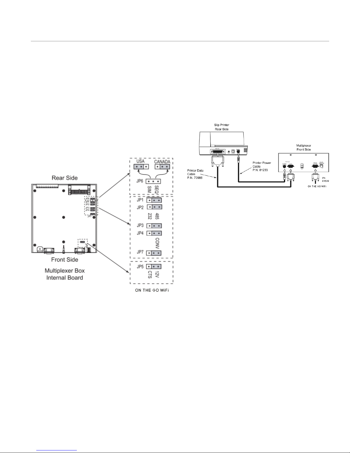
a. Set the Internal Jumpers. Using a 5/64” Allen
wrench, remove the 8 black socket head screws
and remove the cover of the multiplexer box.
b. Locate JP5 and move the jumper from the CTS
position to the 12V position.
c. Jumpers JP1, JP2, JP3, JP4 and JP7 should be
positioned on the right.
d. Replace the cover on the multiplexer box.
e. Install the Multiplexer and connect the printer.
Install the multiplexer in its final location and
make sure it is grounded properly. Next, plug
in the data and the power cable into the front
side of the multiplexer. Plug the other end of the
cables into the back of the printer.
f. Connect the ON THE GO WiFi adapter to the RS-
232 LAP PAD female DB-9 connection on the
front of the multiplexer box.
g. The green power light on the ON THE GO
WiFi adapter will illuminate when the system
is powered. A separate power supply is not
required.
LC-ON THE GOTM Wireless WiFi Adapter WWW.LCMETER.COM 9
Page 10

IV. CONNECTING TO A NEW DUAL METER SYSTEM
h. Connect Register Data and Power cables. Run
the register’s data and power cables through
split loom, under the vehicle and connect them
to the multiplexer box as shown:
i. Set up the Register’s Communication Protocol
NOTE: Make sure the register is powered OFF before
moving the jumper or the cables.
In order to communicate with a computer device,
the cabling must be modified inside both register
heads.
• Remove the RED and VIOLET cable from terminal
block J3 and wire them into terminal J2.
• Move the RED wire from pin 46 on terminal block
J3 to pin 24 on terminal block J2.
Move jumper to B position
for ON THE GO WiFi
• Move the VIOLET cable from pin 48 on terminal
block J3 to pin 25 on terminal block J2.
• Move the J10 jumper to the B (485) position.
j. The green power light on the ON THE GO
WiFi adapter will illuminate when the system
is powered. A separate power supply is not
required.
10 WWW.LCMETER.COM
840405
LC-ON THE GOTM Wireless WiFi Adapter
Page 11

V. CONNECTING TO EZ COMMAND OR EZ COMMAND LITE
12. Using the ON THE GO
Connect to EZ Command or EZ Command
Lite
a. Connect ON THE GO WiFi Adapter to a
Lectrocount register using a lap pad adapter or
multiplexer box.
b. Turn power on. The green power light on the ON
THE GO WiFi Adapter will illuminate.
c. Connect to the WiFi adapter via a local PC or
tablet.
d. Open EZ Command or EZ Command Lite on the
PC or tablet.
e. Select the Tools tab at the top of the program
window
TM
WiFi Adapter to
f. From the Tools drop down menu, select Setup
Communication:
g. In the Setup Communication window, select IP
Config. Enter Local IP Port, Node IP Address,
and Node IP Port as follows:
SPECIFICATIONS FOR P/N: 81538
SECURITY/PROTECTION . . 256-bit AES Encryption
BAUD RATE . . . . . . . . . 19200 bps – setting from
. . . . . . . . . . . . . . . . the factory
DATA RATES AVAILABLE . . 300 bps to 921,600 bps
THRESHOLD . . . . . . . . 100 bytes
PROTOCOL . . . . . . . . . TCP
LOCAL PORT . . . . . . . . 10001
CONNECTOR(S) . . . . . . . Serial: DB9 - DTE (male)
. . . . . . . . . . . . . . . .
LC-ON THE GOTM Wireless WiFi Adapter WWW.LCMETER.COM 11
ANTENNA . . . . . . . . . . 4.3 inch WiFi Antenna
. . . . . . . . . . . . . . . . Omni-directional ‘Rubber
. . . . . . . . . . . . . . . . Duck’ Antenna, 2.4 GHz,
. . . . . . . . . . . . . . . . 2.5 dBi, Reverse SMA, 50
. . . . . . . . . . . . . . . . Ohm, 20W
TEMPERATURE RANGE
Operating Range . . . . . . -40°C to +85°C (-40°F to
. . . . . . . . . . . . . . . . +185°F)
Humidity Range . . . . . . . 0% to 90% non-
. . . . . . . . . . . . . . . . condensing
Page 12

L I Q UID C O N T R O L S
An IDEX Energy & Fuels Business
105 Albrecht Drive
Lake Bluff, IL 60044-2242
1.800.458.5262
1.847.295.1050
Fax: 1.847.295.1057
www.LCmeter.com
© 2017 Liquid Controls
LC_IOM_ONTHEGOWIFIADAPTER V1: 05/17
 Loading...