

Page 1

Rev: 03.18.2014
Page 1
Trailer Axle Owners Manual FULL
Page 2

TABLE OF CONTENTS
Introduction 3
Safety Information 3
Break-in Period for Electric Drum Brakes 4
Hubs/Drums/Bearings 4
Hub Removal 4
Brake Drum Inspection 5
Bearing Inspection 5
Bearing Lubrication - Oil 6
Bearing Lubrication - Grease 6
Seal Inspection and Replacement 7
Bearing Adjustment/Hub Replacement 7
Electric Brakes 8
How to Use Lippert Electric Brakes Properly 9
General Maintenance - Electric Brakes 9
Brake Adjustment 9
Lubricate Brakes 10
Clean and Inspect Brakes 10
Magnets 10
Shoes and Linings 11
Axle and Suspension Installation 11
Suspension Systems 11
Double-Eye Leaf Springs 12
Torsion Suspension System 13
Inspection 14
Suspension Replacement 14
Wheels 15
Wheel Selection 15
Torque Requirements 16
Tires 17
Introduction to Troubleshooting 18
Troubleshooting 18
Measuring Voltage 18
Troubleshooting Chart 19
Measuring Amperage 20
Amperage Chart 21
Maintenance Schedule 22
Wiring Diagram 23
Pigtail and Coupler Wiring Color Codes 24
3,500LB AXLE WHEEL END COMPONENTS 25
5,200LB AXLE WHEEL END COMPONENTS 30
6,000LB AXLE WHEEL END COMPONENTS 34
7,000LB AXLE WHEEL END COMPONENTS 37
Storage 41
Storage Preparation 41
Extended Storage Inspection Procedures 41
Trip Preparation Checklist 42
Rev: 03.18.2014
Page 2
Trailer Axle Owners Manual FULL
Page 3

Introduction
Combining years of experience in the trailer frame and recreational vehicle industry with the newest
and most innovative technology, Lippert Components, Inc. introduces it’s newest addition, The Axle and
Running Gear Division.
The following publication is designed to give the customer an easy-to-understand operation and service
manual to provide useful and important information. The quality of the Lippert name and the finest
materials utilized in the production of the Axles and Running Gear provide you with hubs, brakes, drums
and spindles that make trailering and braking the finest in the industry.
Quality comes threefold in Lippert Components, Inc.
1. The finest quality materials.
2. The latest technology and design.
3. The quality standards maintained from materials to final assembly.
All three points provide the customer with the best product they can possibly buy and the satisfaction of
knowing they can trust the equipment on which they have spent their hard-earned money.
Lippert Components, Inc. thanks you for purchasing our Axles and Running Gear. When you speak of
Lippert Components, Inc., our quality stands beside you.
Safety Information
The “WARNING” symbol above is a sign that a service or maintenance procedure has a safety risk involved
and may cause serious injury or death if not performed safely and within the parameters set forth in this
manual.
Always wear eye protection when performing service or maintenance to the vehicle. Other safety
equipment to consider would be hearing protection, gloves and possibly a full face shield, depending on
the nature of the service.
This manual provides general service and maintenance procedures. Many variables can change the
circumstances of the service procedure, i.e., the degree of difficulty involved in the service operation and the
ability level of the individual performing the operation. This manual cannot begin to plot out procedures
for every possibility, but will provide the general instructions for effectively servicing the vehicle. In the
event the skill level required or the procedure to difficult, a certified technician should be consulted before
performing the necessary service. Failure to correctly service the vehicle may result in voiding the warranty,
inflicting injury or even death.
The owner’s manual for your unit may have more procedures for service and maintenance.
Rev: 03.18.2014
Page 3
Trailer Axle Owners Manual FULL
Page 4

Break-in Period for Electric Drum Brakes
The break-in period is a typical phenomenon with drum brakes and especially electric drum brakes. Electric
drum brakes will require a break-in period to achieve full performance. This break-in period applies for new
axles and any time new brake shoes and/or magnets are installed as part of regular maintenance.
Lippert Components has found through extensive brake testing that the break-in period for our drum
brakes can range from 20 to 50 brake applications.
Brakes can be seated in by applying approximately 8-10 volts to the trailer brakes at an initial speed of 40
mph and allowing the truck/trailer combination to slow down to 20 or 25 mph. For best results do not use
truck brakes during this procedure. The trailer brakes will seat in faster by using them to stop both the truck
and trailer. The easiest method is to apply the trailer brakes using the manual activation lever located on the
in-cab brake controller. Care must be taken to not overheat the lining material, therefore brake applications
conducted at one mile intervals will suffice. The driver should feel a noticeable difference in the brake
performance during this period, sometimes in as few as 10 applications. After 50 applications, the brake
lining material will be fully cured from the heat and develop close to 100% contact with the brake drum
surface.
This break in period not only seats the shoe lining material but also seats in the brake electromagnets.
During the break-in period, the linings will wear at a faster rate than they do after they are seated in.
NOTE: Brakes should be manually adjusted after the first 200 miles of operation and periodically thereafter,
approx. 3,000 mile intervals.
Hubs/Drums/Bearings
Hub Removal
To remove the hub assembly for inspection, maintenance or service, follow the six (6) steps below:
Lift unit by the frame and never the axle or suspension. Do not go under unit unless it is properly
supported by jack stands. Unsupported units can fall causing death or serious injury.
1. Lift trailer and support it per manufacturer’s requirements.
2. Remove the wheel.
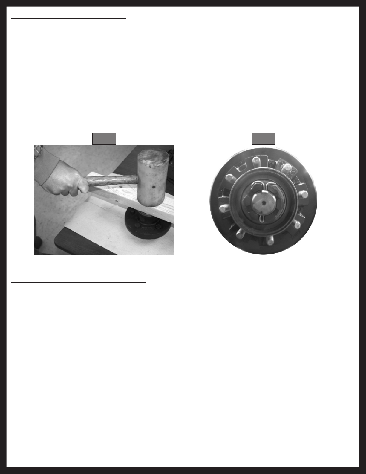
3. Remove the grease cap by prying the edge out of the hub. If equipped with oil lubrication, unscrew oil
cap using a 2½” socket. Let oil drain into pan.
4. Pull the cotter pin from the castle nut and remove the outer spindle nut.
5. Remove the spindle washer.
6. Pull the hub off the spindle. Do not let the outer bearing cone fall free of the assembly. The inner
bearing cone will be contained by the seal and will not fall out.
NOTE: Brakes may need to be adjusted or backed off to remove drum from spindle.
NOTE: A gear puller may be necessary to remove hub from spindle.
Rev: 03.18.2014
Page 4
Trailer Axle Owners Manual FULL
Page 5

Brake Drum Inspection
The brake shoes contact the drum surface and the magnet contacts the armature. These surfaces are
subject to wear and should be inspected periodically.
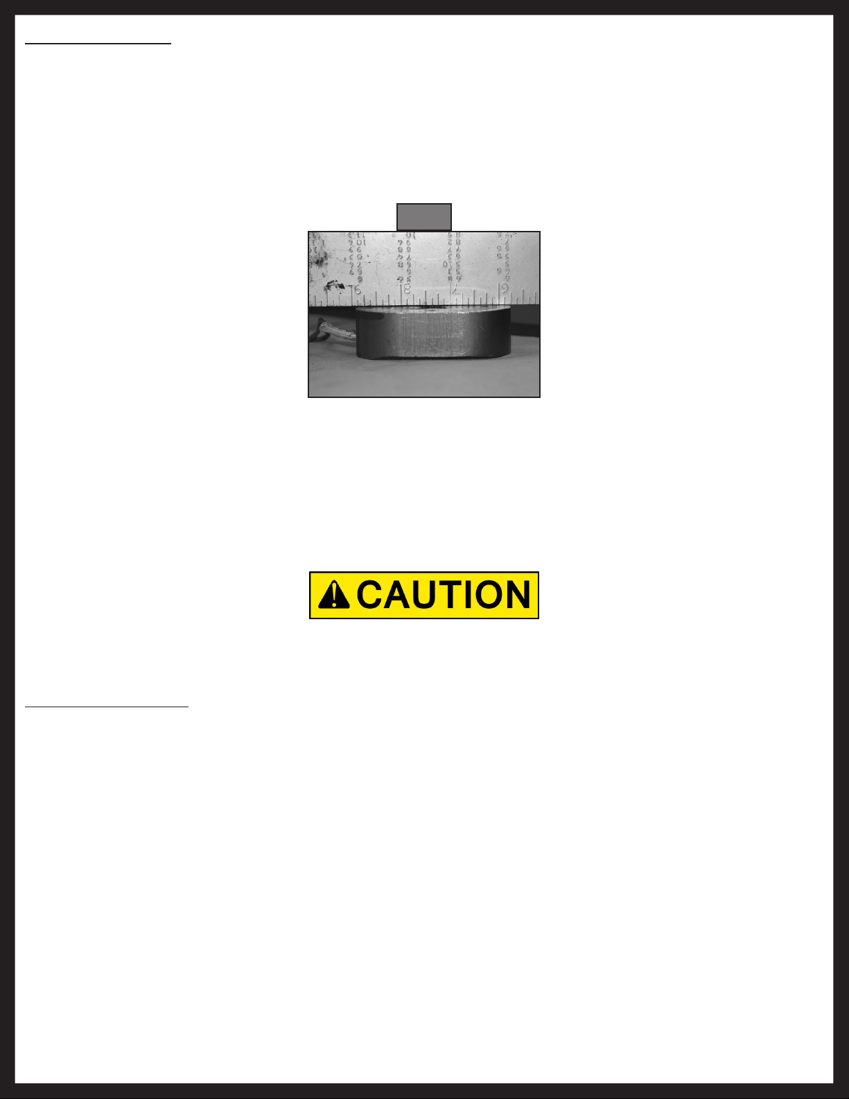
The drum surface should be re-machined if wear is more than .030” or out of round by more than .015”. The
drum should be replaced if scoring or wear is greater than .090”.
The inner surface of the brake drum that contacts the brake magnet is the armature surface. If the armature
surface is scored or worn unevenly, it should not be machined more than .030”. The magnets should be
replaced whenever the armature surface is refaced and vice versa.
NOTE: Ensure that the wheel bearing cavities are clean and free of contamination before reinstalling
bearing and seals. Resurfacing procedures can produce metal chips and dust that can contaminate
the wheel bearings and cause failure.
Drum Maximum Re-bore Diameter
7" 7.09"
10" 10.09"
12" 12.09"
Bearing Inspection
Wash all grease and oil from the bearing cone using a suitable solvent. Dry the bearing with a clean, lint-free
cloth and inspect each roller completely. If any pitting, spalling, or corrosion is present, then the bearing
must be replaced. The bearing cup inside the hub must be inspected.
NOTE: Bearings must always be replaced in sets of one cone and one cup.
Always wear eye protection when servicing the axle, brakes, hubs, springs and wheels. Failure to wear
eye protection may result in serious injury.
Follow the procedure below to replace the bearing cup:
1. Place hub on a flat surface with bearing cup on the bottom.
2. With brass drift punch, lightly tap around the small end of the cup to push it out.
3. Clean the hub bore. Replace the cup by tapping it back in with the brass drift punch. Cup should be
seated against the retaining shoulder in the hub.
Consult Bearing Replacement Chart for proper replacement bearings.
NOTE: Replacing the bearing cup is a very precise process. The cup must be perfectly seated when
replaced. If the cup is not seated correctly, damage to the assembly may not be covered by the
warranty. Consult Lippert Components, Inc. prior to replacing bearing and bearing cup. The trailer
should be taken to a certified service center for this work to be done.
Do not mix Lithium, calcium, sodium or barium complex greases. Chemical compatibility problems may
occur. If you are changing from one chemical grease to another, be sure all old grease is removed prior to
applying new grease. If the old grease is not removed completely, chemical compatability may result in
component failure or damage.
Rev: 03.18.2014
Page 5
Trailer Axle Owners Manual FULL
Page 6

Bearing Lubrication - Oil
If your axles are equipped with oil lubricated hubs, then your lubrication procedure is to periodically fill the
hub with a high quality hypoid gear oil to the level indicated on the clear plastic oil cap. The oil can be filled
through the rubber plug hole in the cap.
Bearing Lubrication - Grease
Bearing grease should be replaced every 12,000 miles or 12 months, whichever comes first. Remove all
old grease from wheel hub and bearings first. Bearings should be packed by machine if possible. Packing
bearings by machine is preferable; however, packing by hand is a viable alternative.
Follow these procedures to repack bearings by hand:
1. Place grease into the palm of your hand (Fig. 1).
2. Press widest end of bearing into the outer edge of the grease pile, forcing grease into the inner area of
the bearing between two adjacent rollers (Fig. 2).
3. Repeat this process while turning bearing from roller to roller until all rollers are coated.
4. Apply a light coat of grease into the bearing cup surface.
5. Reassemble bearing into cup.
Fig. 1
Fig. 2
Recommended Wheel Bearing Grease Specifications
Thickener Type Lithium Complex
Dropping Point 230°C (446°F) Minimum
Consistency NLGI No. 2
Additives EP, Corrosion, & Oxidation Inhibitors
Base Oil Solvent Refined Petroleum Oil
Base Oil Viscosity @40°C (104°F) 150cSt (695 SUS) Minimum
Viscosity Index 80 Minimum
Pour Point -10°C (14°F) Minimum
Rev: 03.18.2014
Approved Sources
Mobil Oil Mobilgrease HP
Exxon/Standard Ronex MP
Kendal Refining Co. Kendall L-427
Ashland Oil Co. Valvoline Val-plex EP Grease
Pennzoil Prod. Co. Premium Wheel Bearing Grease 707L
Page 6
Trailer Axle Owners Manual FULL
Page 7
Seal Inspection and Replacement
Always check the seal to make sure that it is not damaged, nicked, cracked or torn and is in good working
order. If there is any question of condition, replace the seal.
Procedure to replace seal:
1. Pull seal from the hub with a seal puller. Never push the seal out with the bearing. The bearing may get
damaged.
2. Apply a PERMATEX sealant to the outside of the new seal.
NOTE: Do not use PERMATEX on rubber encased seals.
3. Tap the new seal into place using a clean, hardwood block (Fig. 3).
NOTE: When installing a new oil seal, be sure side marked “AIR SIDE” is away from bearing cone.
Fig. 3 Fig. 4
Bearing Adjustment/Hub Replacement
To adjust bearings or replace removed hub, follow procedures below:
1. Place hub, bearing, washers and castle nut back on axle spindle in the reverse order from which they
were removed. Castle nut should be torqued to 50 ft.-lb. Hub will rotate during this process.
2. Loosen castle nut to back off the torque.
3. Tighten castle nut finger tight until snug.
4. Insert cotter pin. If cotter pin does not line up with hole, back castle nut up slightly until pin can be
inserted (Fig. 4).
5. Bend cotter pin over to lock nut in place. Nut should be free to move with only the cotter pin keeping
it in place.
Rev: 03.18.2014
Page 7
Trailer Axle Owners Manual FULL
Page 8
Electric Brakes
The basic structure of the Electric Brakes on your trailer will resemble the brakes on your car or tow vehicle,
with one major difference; your trailer implements an Electric Actuation system and your tow vehicle utilizes
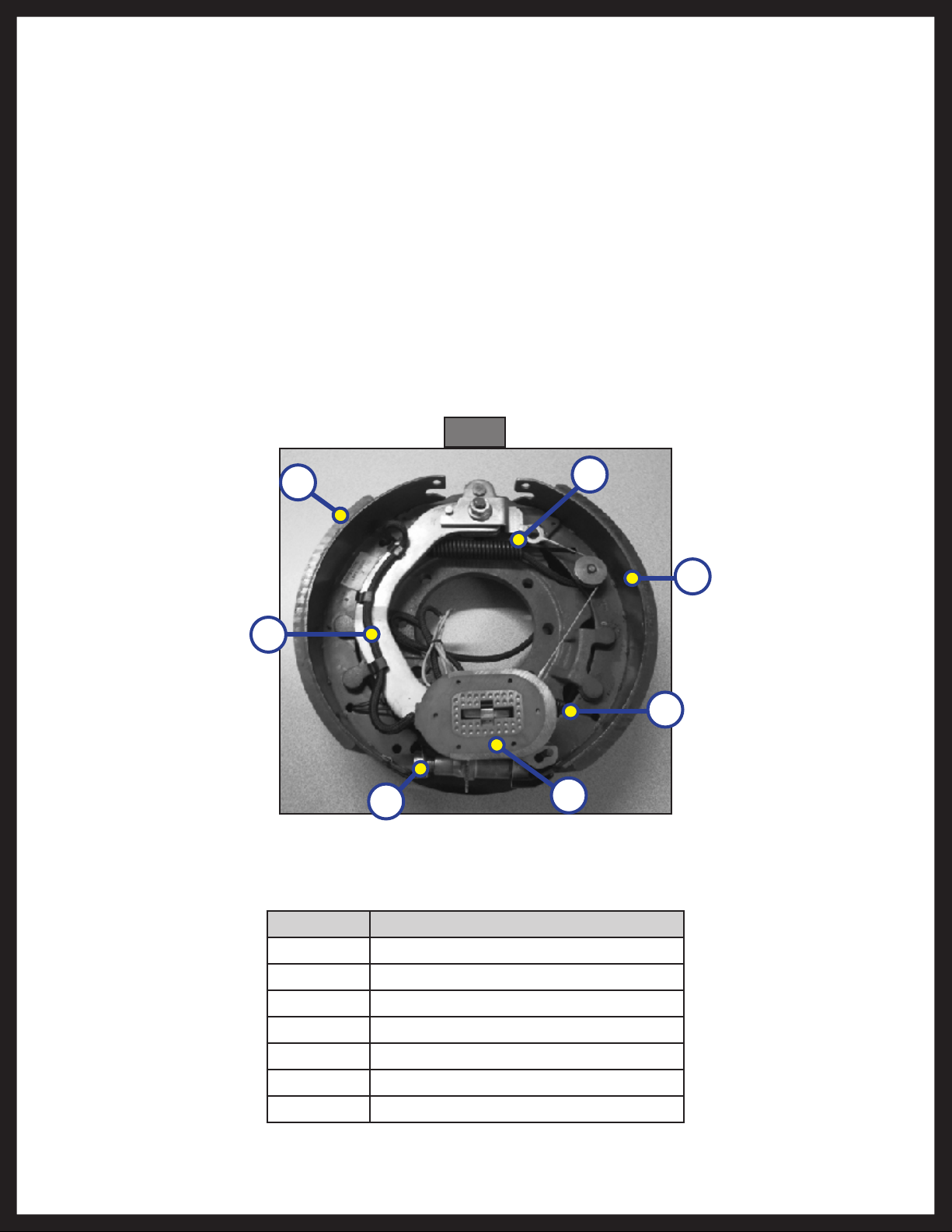
a hydraulic system. The Electric Braking System operates in the following order of steps: (Refer to the Electric
Braking System Diagram and the brake diagram below to follow along.)
6. Electric current is supplied to the trailer’s braking system when the tow vehicle’s brakes are applied.
7. From the tow vehicle’s battery, the electricity flows to the brake’s electromagnet.
8. When energized the magnets are attracted to the rotating surface of the drums.
9. This moves the actuating levers in the direction the drums are turning.
10. The actuating cam at the end of the shoe forces the primary shoe out to the drum surface.
11. The force of the primary shoe actuates the secondary shoe to contact the drum.
12. The force applied to the brake drum can be increased by elevating the current flow to the magnet.
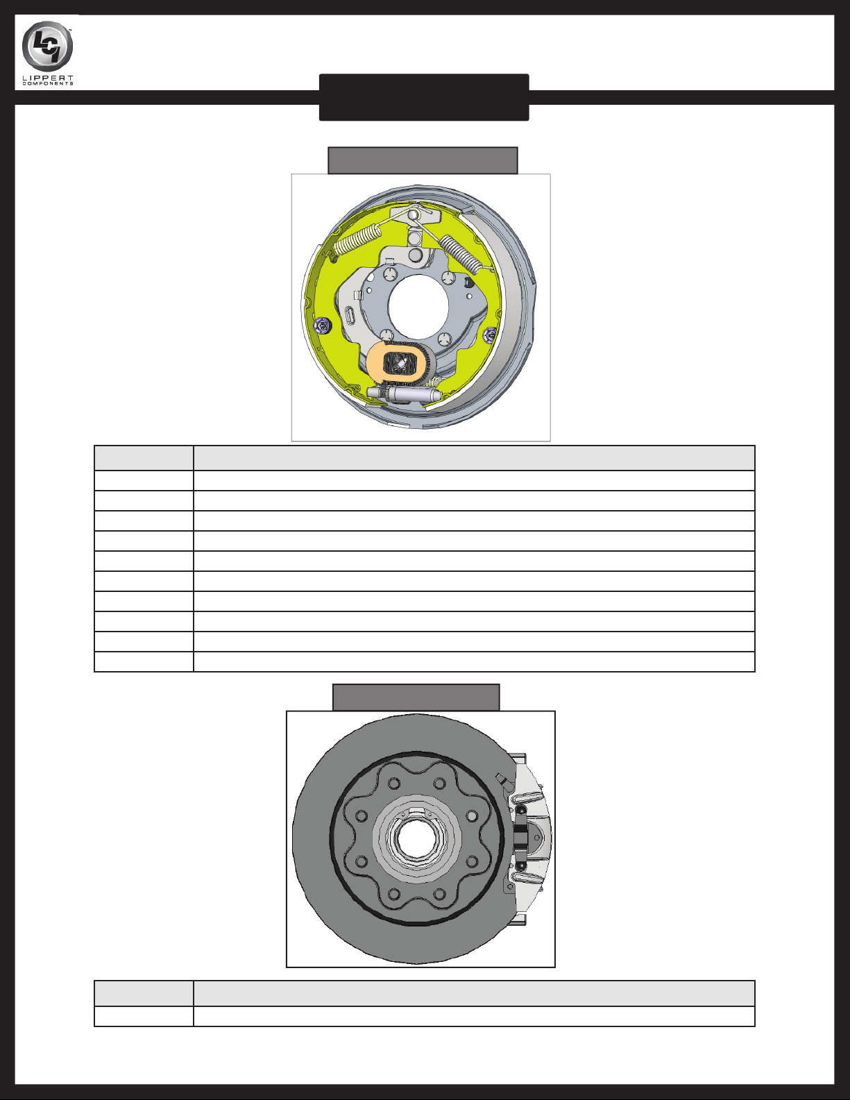
Fig. 5
A
B
C
Callout Description
A Primary Shoe
G
F
E
D
Rev: 03.18.2014
B Actuating Lever
C Adjuster
D Magnet
E Adjusting Spring
F Secondary Shoe
G Retracting Spring
Page 8
Trailer Axle Owners Manual FULL
Page 9

How to Use Lippert Electric Brakes Properly
The Lippert Components, Inc. Electric Braking System is synchronized with the tow vehicle brakes. Never
attempt to stop the combined load of the tow vehicle and the trailer by using either the tow vehicle brakes
or the trailer brakes only. They are designed to work together.
Small manual adjustments may occasionally be necessary to accommodate changing loads and driving
conditions. Synchronization of tow vehicle to trailer braking can only be accomplished by road testing.
Locking up, excessive grab, or delayed application is quite often due to the lack of synchronization between
the tow vehicle and the trailer being towed. High voltage (2V+), Low voltage (2V-) or improperly adjusted
brakes are the most common causes of these problems and can be easily remedied.
Prior to any adjustments, your trailer brakes should be burnished-in by applying the brakes 20-30 times
with a 20 m.p.h. decrease in speed, e.g. 40 m.p.h. to 20 m.p.h. Allow ample time for brakes to cool between
application. This allows the brake shoes and magnets to begin seating to the brake drum.
Trailer Wire Gauge Chart
Wire Gauge and Type Number of Axles Length of Run
16 Ga Stranded Copper 1 N/A
14 Ga Stranded Copper 2
12 Ga Stranded Copper 2 or 3
Under 30ft. (9.1m) from
hitch to center of axles
Over 30ft. (9.1m) from
hitch to center of axles
General Maintenance - Electric Brakes
Brake Adjustment
Prior to testing or adjusting brakes, be sure area is clear of any persons and vehicles. Failure to perform
test in a clear area may result in death or serious injury.
Lippert Components, Inc. Electric Brakes are automatic adjust only. If manual adjusting is needed, the
following 6-step procedure can be utilized. The brakes should be adjusted in the following manner:
1. Jack up trailer and secure on adequate capacity jack stands. Follow trailer manufacturer’s
recommendations for lifting and supporting the unit. Make sure the wheel and drum rotates freely.
Lift unit by frame and never the axle or suspension. Do not go under unit unless it is properly supported
by jack stands. Unsupported units can fall causing death or serious injury.
2. Remove the adjusting hole cover from the adjusting slot on the bottom of the brake backing plate.
3. With a screwdriver or standard adjusting tool, rotate the starwheel of the adjuster assembly to expand
the brake shoes. Adjust the brake shoes out until the pressure of the linings against the drum makes
the wheel very difficult to turn.
4. Then rotate the starwheel in the opposite direction until the wheel turns freely with a slight lining drag.
NOTE: A second screwdriver will be needed to push the auto adjusting lever away from the adjuster
starwheel so that the starwheel can be rotated backwards.
5. Replace the adjusting hole cover and lower the wheel to the ground.
6. Repeat the above procedure on all brakes. For best results, the brakes should all be set at the same
clearance.
Rev: 03.18.2014
Page 9
Trailer Axle Owners Manual FULL
Page 10

Lubricate Brakes
Prior to reassembling the brake drum assembly, remember to apply a light film of white grease or an antiseize compound on the brake anchor pin, the actuating arm bushing and pin, and the areas on the backing
plate that are in contact with the brake shoes and magnet lever arm. In addition apply a light film of grease
on the actuating block mounted on the actuating arm.
Clean and Inspect Brakes
In the event the braking system encounters symptoms of improper application or failure, immediate
inspection and service must be implemented. During normal use, servicing the braking system once a year
is considered normal. Increased usage will require service on a regulated schedule based on 3000-6000 mile
increments. As magnets and shoes become worn, they need to be changed to maintain maximum braking
capability.
Be sure, when disassembling brakes for cleaning, to clean the backing plate, magnet arm, magnet and
shoes. Also, make sure that any and all parts removed for cleaning are placed back into the same brake drum
assembly. This is also an excellent time to check for parts that have become loose or worn.
Potential Asbestos Dust Hazard.
Older brake linings have the potential to contain asbestos dust, which has been linked to serious or fatal
illnesses. Certain precautions must be taken when servicing brakes:
1. Avoid creating and/or breathing any brake dust.
2. Do not machine, file, or grind the brake linings.
3. Remove with a damp brush or cloth. Dry brushing or compressed air will cause the dust particles to
become airborne.
Magnets
This electric braking system utilizes an electromagnet to actuate the brake shoes. These high-quality
magnets provide superior force and friction to safely and effectively stop the trailer. These magnets should
be inspected and serviced on the same schedule as the rest of the axle system, at least once a year for
normal use and more often if the trailer is used extensively. Abnormal or uneven wear is a sign that the
magnet needs to be replaced. Check the surface of the magnet with a straight edge to check for uneven
wear. The surface of the magnet should be completely flat.
If the magnet’s coil is exposed in any way, even if normal wear is evident, the magnets should be replaced
immediately. If the electromagnets are replaced, the drum armature surface should also be refaced. If
a magnet is replaced on one side of an axle, it is recommended that the magnet on the opposite brake
assembly also be replaced to ensure even braking capacity.
Figure 6 (Page 11) shows an Electro-Magnet with little or no wear. If there are any pronounced gaps on the
surface of the Electro-Magnet, the magnet should be replaced.
Rev: 03.18.2014
Page 10
Trailer Axle Owners Manual FULL
Page 11
Shoes and Linings
Linings should be replaced if the material is worn to ⁄” or less. Shoes should also be replaced if they
become contaminated with grease or oil or have become scored, pitted or gouged. Heat cracks are normal
and rarely require attention. When replacing shoes, both shoes on the same brake and the brakes on the
same axle should all be replaced at the same time, once again ensuring even braking capacity.
After replacing shoes and linings, your trailer brakes should be burnished-in by applying the brakes 20-30
times with a 20 m.p.h. decrease in speed, e.g. 40 m.p.h. to 20 m.p.h. Allow ample time for brakes to cool
between application. This allows the brake shoes and magnets to begin seating to the brake drum.
Fig. 6
Axle and Suspension Installation
The single most important portion of axle installation is parallel alignment of the trailer axle(s) to the tow
vehicle or drive axle(s). Parallel installation allows for correct and safe control, prolonged tread life and will
all but eliminate dog-tracking. Proper alignment is most readily achieved by measuring from the center of
the trailer king pin to the center of each end of the axles.
Lippert Components, Inc. tubular axles are made of high strength steel to prevent metal fatigue and provide
the best possible welding conditions. The round tubular axles allow for even and uniform structure.
Always wear eye protection when servicing the axle, brakes, hubs, springs and wheels. Failure to wear eye
protection may result in serious injury.
Suspension Systems
The suspension systems incorporated into Lippert Component, Inc. axles are designed to provide the
following benefits:
1. Attach the axle to the trailer.
2. Dampen the effects of road shock.
3. Provide stability to the trailer.
All Lippert suspension systems are available in single and multiple axle configurations. For specific or
custom applications, please contact Lippert Components, Inc. Axle Division.
Rev: 03.18.2014
Page 11
Trailer Axle Owners Manual FULL
Page 12

Double-Eye Leaf Springs
Double-eye leaf springs have eyes at either end of the spring assembly with nylon bushings to assist in
preventing wear. U-bolts hold the springs to the axle with a plate.
The articulation of this suspension occurs when the eyes rotate on the wear surfaces provided in eyes of the
springs and on the equalizers. This suspension is also available in single and multiple axle configurations.
In trailers with 2 or more axles, the additional movement is maintained by an equalizer. This feature allows
for even load handling from axle to axle.
Double-eye suspension systems are available on 8,000 lb. axles. Tandem and triple axle mounting kits are
available for both 33” and 35” axle spacing.
Front Hanger
Shackle Link Center Hanger
Fig. 7
Shackle Bolts
Tie Plate
Equalizer
Spring Axle Torque Specifications
Bolt Type Axle Capacity Maximum Torque
2K 25 ft-lb
Rear Hanger
Rev: 03.18.2014
U-Bolts
3.5K with ½ " 50 ft-lb
5.2K 65 ft-lb
6-8K 90 ft-lb
Minimum Torque Maximum Torque
Shackle Bolts 30 ft-lb 50 ft-lb
Page 12
Trailer Axle Owners Manual FULL
Page 13
Torsion Suspension System
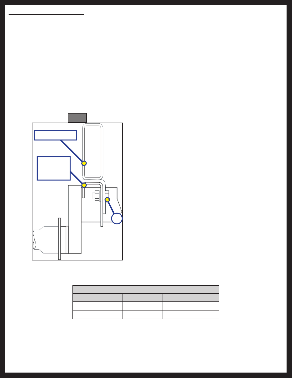
1. The Lippert Components, Inc. Torsion Suspension system is designed to offer superior qualities over
leaf spring technology. The Lippert Components, Inc. Torsion Suspension system is bracketed to the
trailer’s frame and housed inside the trailer axle’s tube.
2. The spindle is connected to a swing arm, the swing arm is connected to a square inner bar that is
sheathed in rubber and as the swing arm rotates and experiences the torque and resistance of driving
conditions, the characteristics of the rubber absorb and distribute the load providing benefit over leaf
spring suspensions.
3. The Lippert Components, Inc. Torsion Suspension system requires very little attention in regards to
maintenance. Normal inspection of the entire Lippert Components, Inc. Trailer Axle system can be
applied to the Torsion Suspension system. See inspection procedures for system components in this
manual.
Fig. 8
Outside Frame
Outside
Bracket
Dimension
NOTE: For Torsion installation, mount axle bracket to
frame bracket (Fig. 8) and torque fasteners
as specified in the chart below.
NOTE: Washer(s) must be placed against the slotted
hole in the axle bracket (Fig. 8A).
NOTE: Low profile brackets have plain round holes.
A
Rev: 03.18.2014
Torsion Axle Torque Specifications
Axle Size Bolt Size Torque Range
#8 - #9 ½ " 70-90 ft-lb
#10 - #13 ⁄" 120-150 ft-lb
Page 13
Trailer Axle Owners Manual FULL
Page 14

Inspection
All the components of your suspension system should be visually inspected for signs of wear, damage or
loose fasteners at least every 6,000 miles. When replacing or tightening loose fasteners, consult the torque
specs on page 13 for correct torque values.
Worn spring eye bushings or sagging or broken springs should be replaced using the following method:
1. Support the trailer with the wheels just off the ground. Follow the trailer manufacturer’s
recommendations for lifting and supporting the unit.
2. After the unit is properly supported place a suitable block under the axle tube near the end to be
repaired. This block is to support the weight of the axle only so that suspension components can be
serviced or replaced.
3. Disassemble the U-bolts, nuts, and tie plates.
4. Remove the spring eye bolts and the spring.
5. If the spring eye bushings are to be replaced, press out the old bushing by hand or tapping out with a
punch.
6. Free-floating nylon bushing needs no lubrication. Press the new bushing into the spring eye by hand
or gently tapping it in with a bounce less rubber or plastic mallet.
7. Reinstall repaired or replaced components in reverse order.
NOTE: For multiple axle units, the weight of each axle must be supported as outlined in Step 2 before
disassembly of any component of the suspension system.
Lift unit by the frame and never the axle or suspension. Do not go under unit unless it is properly
supported by jack stands. Unsupported units can fall causing death or serious injury.
Always wear eye protection when servicing the axle, brakes, hubs, springs and wheels. Failure to wear
eye protection may result in serious injury.
If the equalizer or equalizer bushings must be replaced, follow the instructions above for lifting and
supporting the trailer unit and then proceed as follows:
1. With both axles blocked up, remove the spring eyebolt, keeper bolt, and equalizer bolt from the
equalizer to be repaired or replaced.
2. Press the old nylon bushing out of the equalizer.
3. Reassemble in reverse order.
Suspension Replacement
1. Make sure springs are on straight. Align spring eyes to front hanger. Insert spring eye bolts but do not
torque at this point.
2. Assemble springs into equalizer.
3. After leveling equalizer to frame, torque equalizer nuts and spring eye nuts to a minimum of 30 ft.-lb.
and a maximum of 50 ft-lb.
Rev: 03.18.2014
Page 14
Trailer Axle Owners Manual FULL
Page 15

Wheels
Wheel Selection
When specifying or replacing your trailer wheels it is important that the wheels, tires, and axle are properly
matched. The following characteristics are extremely important and should be thoroughly checked when
replacement wheels are considered:
1. Bolt Circle. Wheels have many bolt circle variations and some are so close that it could be possible to
attach an inappropriate wheel that does not match the axle hub.
2. Capacity. Wheel load capacity should match tire and trailer max. load ratings.
3. Offset. The relationship of the center line of the tire to the hub face of the axle should match any
replacement. Failure to match offset may result in reducing the carrying capacity of your axle.
4. Rim Contour. Replacement wheels should be direct replacements to match the rim contour.
Use only rim contours suggested by manufacturer. Failure to use correct rim contour may cause
dramatic separation of tire and wheel and could cause death or serious injury.
Attempting to modify or repair a wheel can cause unsafe conditions that may result in an explosion. Air
pressure on a weakened or cracked rim can cause death or serious injury.
Rev: 03.18.2014
Page 15
Trailer Axle Owners Manual FULL
Page 16

Torque Requirements
It is extremely important to apply and maintain proper wheel mounting torque on your trailer axle. Torque
wrenches assure the proper amount of torque is being applied to a fastener. Use no other method to torque
fasteners.
Proper and accurate torque must be maintained to prevent wheels from loosening, studs from cracking and/
or breaking or other possible hazardous breakage resulting in death or serious injury.
Be sure to use only the fasteners matched to the cone angle of your wheel (usually 60°or 90°). The proper
procedure for attaching your wheels is as follows:
1. Start all bolts or nuts by hand to prevent cross threading.
2. Tighten bolts or nuts in the following sequence (see Wheel Torque Requirement Chart below).
3. Tightening fasteners should be done in stages. Follow the recommended sequence (Fig. 9), tighten
fasteners per wheel torque requirements chart below.
4. Wheel nuts/bolts should be torqued before first road use and after each wheel removal. Check and
re-torque after the 10 and 25 miles and again at 50 miles. A periodic check during regular service is
recommended.
Wheel Torque Requirement Chart
Torque Sequence
Wheel Size Stud Size
1st Stage 2nd Stage 3rd Stage
14" 1/2" 20-25 ft-lbs 50-60 ft-lbs 90-120 ft-lbs
15" 1/2" 20-25 ft-lbs 50-60 ft-lbs 90-120 ft-lbs
16" 1/2" 20-25 ft-lbs 50-60 ft-lbs 90-120 ft-lbs
16.5" x 6.75" 1/2" 20-25 ft-lbs 50-60 ft-lbs 90-120 ft-lbs
16" 9/16" 20-25 ft-lbs 60-70 ft-lbs 120-130 ft-lbs
16.5" x 6.75" 9/16" 20-25 ft-lbs 60-70 ft-lbs 120-130 ft-lbs
16" Dual and 17.5" Cone Nut 5/8" 50-60 ft-lbs 100-120 ft-lbs 190-210 ft-lbs
16" Dual and 17.5" Flange Nut 5/8" 50-60 ft-lbs 150-200 ft-lbs 275-325 ft-lbs
14.5" Demount 5/8" Tighten sequentially to 85-95 ft-lbs
Fig. 9
1
1
6
4
3
6
3
1
3
2
Rev: 03.18.2014
8
4
5
2
Page 16
5
4
2
Trailer Axle Owners Manual FULL
7
5
Page 17

Tires
Prior to mounting tires onto wheels, be sure the rim size and contour are approved by the Tire and Rim
Association Yearbook or the tire manufacturers catalog. In addition, confirm that the tire will carry the rated
load. If the load is not evenly distributed on all tires, use the tire rated for the heaviest wheel position.
The Rubber Manufacturers Association or the tire manufacturers guidelines should be consulted for
mounting procedures.
Tire inflation pressure is the most important factor in tire life. Tire pressure should always be what is
recommended by the manufacturer for the load. Always check pressure cold before operation. DO NOT
bleed air from tires when they are hot. Check inflation pressure weekly during use to insure maximum tire
and tread life.
The following tire wear diagnostic chart will help you pinpoint the causes and solutions of tire wear
problems.
NOTE: Tire wear should be checked frequently because once a wear pattern becomes firmly established in a
tire it is difficult to stop, even if the underlying cause is corrected.
Problem Probable Cause Corrective Action
Center Wear Over-inflation
Edge Wear Under-inflation
Side Wear Loss of camber or overloading
Toe Wear Incorrect Toe-in
Cupping Out-of-balance
Adjust pressure to particular load
per tire catalog.
Adjust pressure to particular load
per tire catalog.
Make sure load does exceed
axle rating. Call Lippert Service &
Warranty to advise.
Call Lippert Service & Warranty to
advise.
Check bearing adjustment and
balance tires.
Flat Spots Wheel lockup and tire skidding
Rev: 03.18.2014
Page 17
Avoid sudden stop if possible and
adjust brakes.
Trailer Axle Owners Manual FULL
Page 18

Introduction to Troubleshooting
The following section is a guideline for ensuring operation of your braking system. The safety of you, those
traveling with you and those sharing the road paramount and it starts with the ability to safely stop the tow
vehicle and the towed vehicle.
Troubleshooting
Most brake malfunctions can be corrected by utilizing the Troubleshooting Chart on the next page.
Mechanical failure is the most common form of malfunction, however, if the brake system fails and it’s not
mechanical, it is usually electrical. A Voltmeter and Ammeter are essential tools to diagnose these problems.
Mechanical problems are mostly self-evident; something is bent or broken. Consult the troubleshooting
chart on Page 19 to determine the probable cause and corrective actions for a variety of issues with the
braking system.
Remember to use only Lippert Components, Inc. replacement parts on these systems. Consult the Limited
Warranty or call our Service Department for any other related issues.
Measuring Voltage
The Braking System voltage is measured at the two lead wires of the magnet on any brake. Use the pin
probes inserted through the insulation of the lead wires. To ensure that the battery is indicating a full
charge, the towing vehicle engine should be running with the trailer coupler connected when checking the
voltage.
Voltage in the system should begin at 0 volts and, as the brake pedal of the tow vehicle is applied, voltage
will gradually increase to about 12 volts. If the system does not indicate at least 12 volts, problems may
occur in the wiring of the system, the battery or alternator of the tow vehicle.
When the brakes are applied, a gradual increase in voltage is preferable to a quick increase to 12 volts. A
gradual increase in voltage ensures smooth and firm trailer braking. A quick increase in voltage will cause
the braking system to feel like the trailer is grabbing too quickly.
Taking a Voltage reading is usually done with probes inserted into the wire connector (Fig. 10).
Fig. 10
Rev: 03.18.2014
Page 18
Trailer Axle Owners Manual FULL
Page 19

Troubleshooting Chart
Problem Probable Cause Corrective Action
Open circuits Find and correct
No brakes
Weak brakes
Locking brakes
Intermittent brakes
Brakes pull to one
side
Short circuits Test and correct
Severe under-adjustment Adjust brakes
Grease or oil on magnets or linings Clean or replace
Corroded connections Clean and correct cause of corrosion
Worn linings or magnets Replace
Scored or grooved brake drums Machine or replace
Improper synchronization Correct
Under-adjustment Adjust brakes
Glazed Linings Re-burnish or replace
Under-adjustment Adjust
Improper synchronization Correct
Loose, bent or broken brake components Test and correct
Out-of-round brake drums Machine or replace
Insufficient wheel load Adjust system resistor and synchronize
Broken wires Test and correct
Loose connections Repair or replace
Faulty ground Find and repair
Wrong magnet lead wire color Adjust
Incorrect adjustment Correct
Grease or oil on linings or magnets Clean or replace
Broken wires Find and repair
Bad connections Find and repair
Harsh brakes
Under-adjustment Adjust
Improper synchronization Correct
Under-adjustment Adjust
Lack of lubrication Lubricate
Noisy brakes
Broken Replace component
Incorrect brake components Correct
Grease or oil on linings or magnets Clean or replace
Surging brakes
Out-of-round or cracked brake drums Machine or replace
Over-adjustment Readjust
Out-of-round brake drums Machine or replace
Incorrect brake components Replace
Dragging brakes
Loose, bent or broken brake components Replace
Faulty breakaway switch Repair or replace
Loose wheel bearing adjustment Adjust
Bent spindle Replace Axle
NOTE: If all trailer lights and brakes do not work, check your wiring plug connection and make sure the ball
is making solid contact with the coupler (that is how a trailer is grounded). Too much grease or not
using dielectric grease on the ball and coupler can cause this to happen.
Rev: 03.18.2014
Page 19
Trailer Axle Owners Manual FULL
Page 20

Measuring Amperage
The Braking System amperage is the amount of current flowing through the system when all magnets have
been energized. The amperage will change proportionately with the voltage. To ensure that the battery is
indicating a full charge, the towing vehicle engine should be running with the trailer coupler connected
when checking the voltage.
If a resistor is used in the brake system, it must be set at zero or bypassed completely to obtain the
maximum amperage reading. Individual amperage draw can be measured by inserting the ammeter in the
line at the magnet you want to check. Disconnect one of the magnet lead wire connectors and attach the
ammeter between the two wires. Consult Amperage Chart on the next page for normal amp readings.
Make sure that the wires are properly reconnected and sealed after testing is completed.
Testing for Amperage can be done with probes (Fig. 11) or alligator clips on the leads or an amp clamp
(Fig. 12).
Fig. 11 Fig. 12
Rev: 03.18.2014
Page 20
Trailer Axle Owners Manual FULL
Page 21

Amperage Chart
Amps/Magnet Two Brakes Four Brakes Six Brakes
3.0 6.0 12.0 18.0
Low or no voltage are the most common problem with the Braking System. Amperage at the brakes is also
a relatively common issue. Common causes of these conditions are:
1. Low quality electrical connections
2. Open circuits
3. Insufficient wire gauge
4. Broken wires
5. Blown fuses (fusing of brakes is not recommended)
6. Short circuits (indicated by high amperage)
Possible causes of shorts are:
1. Shorted magnet coils
2. Bare wires contacting a grounded object
Finding the cause of a short circuit in the system is done by isolating one section at a time. If the high
amperage reading drops to zero by unplugging the trailer, then the short is in the trailer. If the amperage
reading remains high with all the brake magnets disconnected, the short is in the trailer wiring.
All electrical troubleshooting procedures should start at the controller. Most complaints regarding brake
harshness or malfunction are traceable to improperly adjusted or nonfunctional controllers. See your
controller manufacturer’s data for proper adjustment and testing procedures. For best results, all the
connection points in the brake wiring should be sealed to prevent corrosion. Loose or corroded connectors
will cause an increase in resistance which reduces the voltage available for the brake magnets.
Rev: 03.18.2014
Page 21
Trailer Axle Owners Manual FULL
Page 22
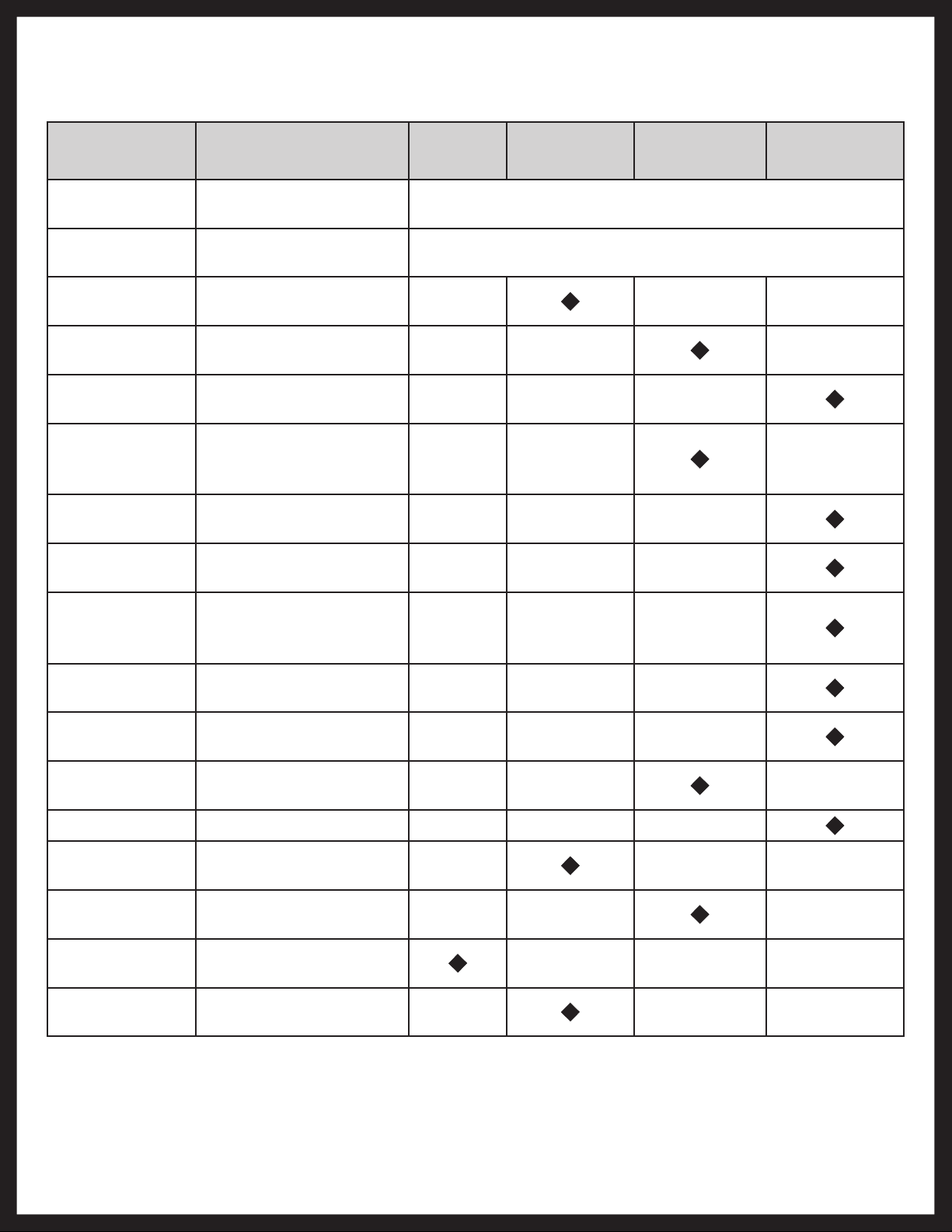
Maintenance Schedule
Item Function Required Weekly
Brakes
Breakaway
System
Brake
Adjustment
Brake
Magnets
Brake Linings
Brake
Controller
Trailer Brake
Wiring
Hub/Drum
Wheel
Bearing
Seals
Springs
Suspension
Parts
Test that they're
operational.
Check battery charge
and switch operation.
Adjust to proper
operating clearance.
Inspect for wear and
current draw.
Inspect for wear or
contamination.
Check for correct
amperage and
modulation.
Inspect wiring for
bare spots, fray, etc.
inspect for abnormal
wear or scoring.
Inspect for corrosion
or wear. Clean and
repack.
Inspect for leakage.
Replace if removed.
Inspect for wear, loss
of arch.
Inspect for bending,
loose fasteners, wear.
3 Months /
3,000 Miles
6 Months /
6,000 Miles
At Every Use
At Every Use
12 Months /
12,000 Miles
Hangers Inspect welds.
Wheel Nuts
and Bolts
Wheels
Tire Inflation
Pressure
Condition
Rev: 03.18.2014
Tire
Tighten to specified
torque values.
Inspect for cracks,
dents, or distortion.
Inflated tires to mfg's.
specifications.
Inspect for cuts, wear,
bulging, etc.
Page 22
Trailer Axle Owners Manual FULL
Page 23
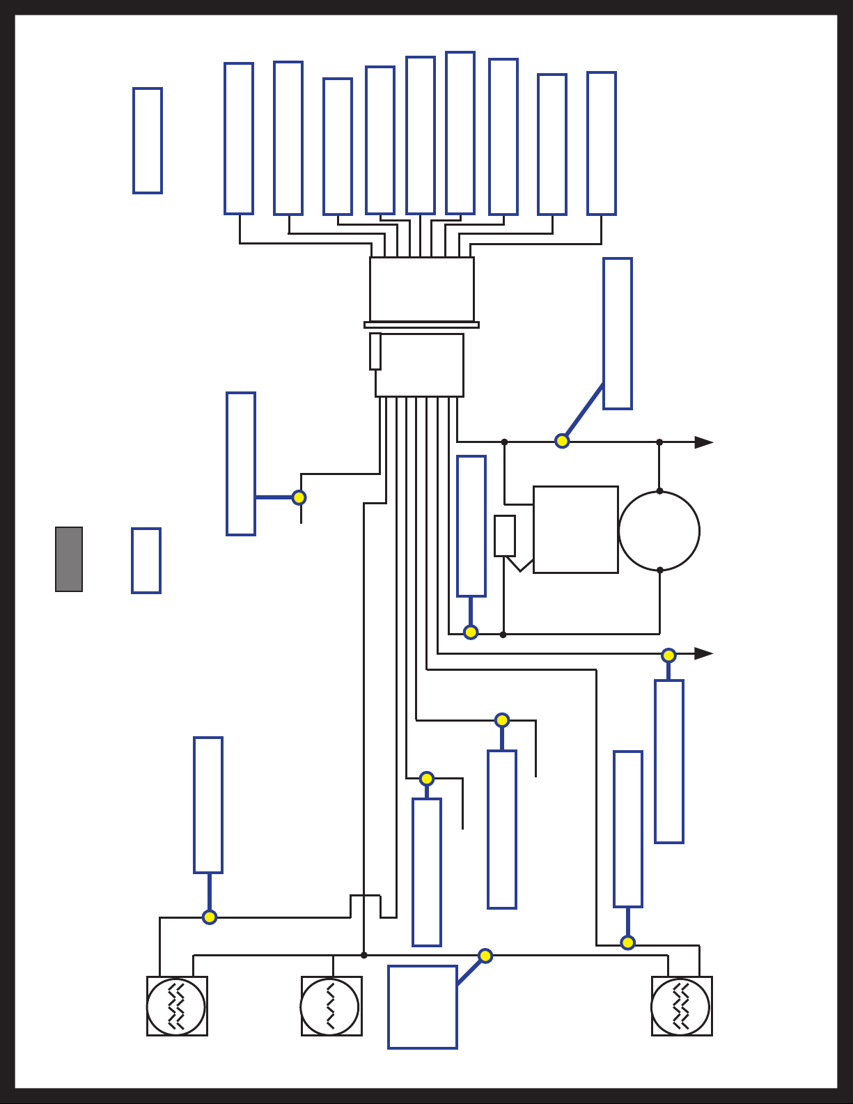
Wiring Diagram
Tow Vehicle
White - Terminal 1
Green - Terminal 3
Red - Terminal 5
Black - Terminal 4
Yellow - Terminal 7
Orange - Terminal 9
Brown - Terminal 6
Blue - Terminal 2
Gray - Terminal 8
White - Terminal 1
Fig. 13
Trailer
Gray - Terminal 8
Auxiliary Circuit
Red - Terminal 5
+ -
Blue - Terminal 2
Common
Ground
Electric
Brake
Auxiliary Circuit
Orange - Terminal 9
Rev: 03.18.2014
Stop and
Left Turn
Signal
License,
Tail and
Running
Lights
Black - Terminal 4
Battery Charge
3
Green -
Terminal
Page 23
Auxiliary Circuit
Yellow - Terminal 7
Brown - Terminal 6
Stop and
Right Turn
Signal
Trailer Axle Owners Manual FULL
Page 24

Pigtail and Coupler Wiring Color Codes
9-PIN COUPLER
STOP &
LH TURN
AUXILIARY
RED
ORANGE
TAIL LIGHTS
CLEARANCE &
GREEN
YELLOW
GROUND
WHITE
BLACK
AUXILIARY
BATTERY
BLUE
BRAKES
CHARGE
BROWN
STOP &
RH TURN
GRAY
AUXILIARY
BROWN - STOP & RH TURN
YELLOW - STOP & LH TURN
STOP &
RH TURN
CHARGE
BATTERY
WHITE - GROUND
GREEN - RUNNING LIGHTS
BLACK
TRAILER LIGHTS PIGTAIL - DOES NOT OPERATE BRAKES
GREEN
7-PIN COUPLER
TAIL LIGHTS
CLEARANCE &
YELLOW
BROWN
STOP &
RED
LH TURN
BRAKES
BLUE
WHITE
AUXILIARY
TRAILER BRAKE AND LIGHT COUPLER - OPERATES BRAKES
GROUND
Rev: 03.18.2014
Page 24
Trailer Axle Owners Manual FULL
Page 25

3,500-LB AXLE WHEEL END COMPONENTS
3,500-LB AXLE WHEEL END COMPONENTS
AXLES AND SUSPENSION
AXLES AND SUSPENSION
G
F
E
D
C
I
H
B
A
Callout Part # Description
A 122065 Rubber plug for lubed grease caps
B
C 122075 Cotter pin
D 122081 Spindle nut, 6 slot
E 119214 Spindle washer, round ID
E1 119215 Spindle washer, for spindle with D-flat
E2 119216 Spindle locking tang washer
Use E1 and E2 in place of C and E if spindle has no hole for cotter pin and has D-flat on all
122067 Dust cap, for 2" bore, super lube
122099 Dust cap, for 2" bore, non-lube
axles built prior to 2009.
Rev: 03.14.2014
F
122089 Outer bearing cone, L44649
125102 Outer bearing cup, L44610
G 126003 Brake hub; 545-1/2"
122092 Inner bearing cone, L68149
H
124296 Inner bearing cup, L68111
I 122087 Grease seal, double lip, 1.72" ID x 2.565" OD
Contact us: Lippert Components Inc. - www.lci1.com/customerservice - Phone: (574) 537-8900 - Email: warranty@lci1.com
Page 25
3500 Axle Webpage
Page 26
3,500-LB AXLE WHEEL END COMPONENTS
AXLES AND SUSPENSION
Electric Brake Assembly
Part # Description
122258 Electric Brake - 10" x 2.25" (Left Hand)
1222581 Electric Brake - 10" x 2.25" APG (Left Hand)
1222582 Electric Brake - 10" x 2.25" Long Lead (Left Hand)
1222583 Electric Brake - 10" x 2.25" Self-Adjusting (Left Hand)
139380 Electric Brake - 10" x 2.25" with Park (Left Hand)
122450 Electric Brake - 10" x 2.25" (Right Hand)
1224501 Electric Brake - 10" x 2.25" APG (Right Hand)
1224502 Electric Brake - 10" x 2.25" Long Lead (Right Hand)
12244503 Electric Brake - 10" x 2.25" Self-Adjusting (Right Hand)
139381 Electric Brake - 10" x 2.25" with Park (Right Hand)
Disc Brake Assembly
Rev: 03.14.2014
Part # Description
130033 Disc Brake; 545 - ½ " Studs
Contact us: Lippert Components Inc. - www.lci1.com/customerservice - Phone: (574) 537-8900 - Email: warranty@lci1.com
Page 26
3500 Axle Webpage
Page 27

3,500-LB AXLE WHEEL END COMPONENTS
AXLES AND SUSPENSION
Hydraulic Brake Assembly
Part # Description
132047 Hydraulic Brake - 10" x 2.25" (Right Hand)
132048 Hydraulic Brake - 10" x 2.25" (Left Hand)
179868 Hydraulic Brake - 10" x 2.25" Free Backing (Right Hand)
179869 Hydraulic Brake - 10" x 2.25" Free Backing (Left Hand)
Rev: 03.14.2014
Contact us: Lippert Components Inc. - www.lci1.com/customerservice - Phone: (574) 537-8900 - Email: warranty@lci1.com
Page 27
3500 Axle Webpage
Page 28

3,500-LB AXLE WHEEL END COMPONENTS
AXLES AND SUSPENSION
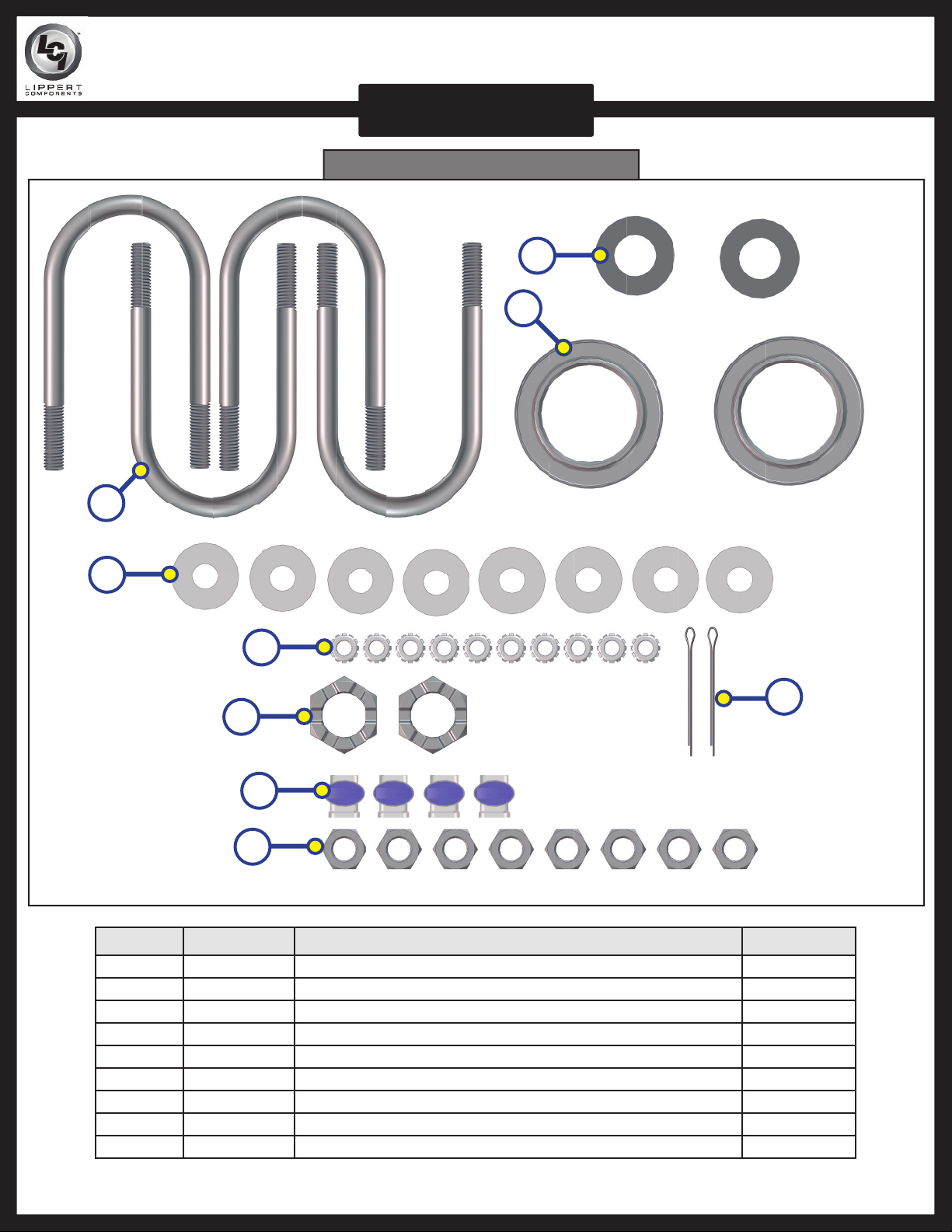
Axle U-Bolt Service Kit (2 ⁄" Beam) Part #173229
B
C
A
D
F
G
H
I
J
Callout Part # Description Quantity
A 122073 U-Bolt; ½ - 20 x 5.1, 2.375 Tube Diameter Yellow Dich 4
B 122087 Seal; 1.666 x 2.565 x 5 (2,800 - 3,500) 2
C 122081 Castle Nut; 1 - 14 2
D 122079 Yellow Zinc Nut; .5 - 20 8
E 122084 Sealed Wire Connector 4
F 119216 Tang Washer; 1.58 x .033 2
G 122075 Cotter Pin; .120 x 1.75 2
H 119215 D-Flat Spindle Washer; 1 x 1.68 2
I 119214 Rounded Spindle Washer; 1 ID x 1.68 OD 2
J 122085 Washer; ⁄ - 20 Hex YZ or SZ 8
K 122086 Washer; ⁄ x ¾ x 11 GA Helical Lock ZInc 8
E
K
Rev: 03.14.2014
Contact us: Lippert Components Inc. - www.lci1.com/customerservice - Phone: (574) 537-8900 - Email: warranty@lci1.com
Page 28
3500 Axle Webpage
Page 29

3,500-LB AXLE WHEEL END COMPONENTS
AXLES AND SUSPENSION
Axle U-Bolt Service Kit (3" Tube) Part #260525
C
D
B
E
G
H
I
F
A
J
Rev: 03.14.2014
K
Callout Part # Description Quantity
A 2139541 U-Bolt; ⁄ - 18 x 6.625, 3" Tube YZ 4
B 122087 Seal; 1.666 x 2.565 x 5 (2,800 - 3,500) 2
C 119214 Round Spindle Washer; 1 ID x 1.68 OD 2
D 122081 Castle Nut; 1 - 14 2
E 122075 Cotter Pin; .120 x 1.75 2
F 122085 Nut; ⁄ - 20 Hex YZ or SZ 8
G 122086 Helical Lock Zinc Washer; ⁄ x ¾ x 11 GA 8
H 170997 Flat USS Hardened Washer; ⁄ 8
I 122084 Sealed Wire Connector 4
J 182274 Nut; ⁄- 18 Hex GR8 8
K 2139521 4 x 6.15 x .8 x .8 2
Contact us: Lippert Components Inc. - www.lci1.com/customerservice - Phone: (574) 537-8900 - Email: warranty@lci1.com
Page 29
3500 Axle Webpage
Page 30

5,200-LB AXLE WHEEL END COMPONENTS
5,200-LB AXLE WHEEL END COMPONENTS
AXLES AND SUSPENSION
AXLES AND SUSPENSION
H
G
F
E
D
I
B
A
Callout Part # Description
A 122065 Rubber plug for lubed grease caps
B
C 122075 Cotter pin
D 122081 Spindle nut, 6 slot
E 179660 Spindle washer, round ID
E1 172888 Spindle washer, for spindle with D-flat
E2 119216 Spindle locking tang washer
Use E1 and E2 in place of C and E if spindle has no hole for cotter pin and has D-flat on all axles built prior to 2009
C
122064 Dust cap, for 2.5" bore, super lube
122071 Dust cap, for 2.5" bore, non-lube
F
G
H
I 122088 Grease seal, double lip, 2.25" ID x 3.376" OD
Rev: 03.14.2014
122091 Outer bearing cone, 15123
122996 Outer bearing cup, 15245
122094 Brake Hub; 655; ½ " studs
122095 Brake Hub; 865; ½ " studs
122096 Brake Hub; 865; ⁄" studs
122066 Inner bearing cone, 25580
124287 Inner bearing cup, 25520
Contact us: Lippert Components Inc. - www.lci1.com/customerservice - Phone: (574) 537-8900 - Email: warranty@lci1.com
Page 30
5200 Axle Webpage
Page 31

5,200-LB AXLE WHEEL END COMPONENTS
NOTE: This diagram is
for reference only. The
parts specified here are
only available to the
OEM. Please use the parts
listing on the previous
page for replacement part
information.
AXLES AND SUSPENSION
H
G
I
F
E
D
B
C
A
Callout Part # Description
A 122065 Rubber plug for lubed grease caps
122064 Dust cap, for 2.5" bore, super lube
B
122071 Dust cap, for 2.5" bore, non-lube
C 122075 Cotter pin
D 122081 Spindle nut, 6 slot
E 119214 Spindle washer, round ID
E1 119215 Spindle washer, for spindle with D-flat
E2 119216 Spindle locking tang washer
Use E1 and E2 in place of C and E if spindle has no hole for cotter pin and has D-flat on all
axles built prior to 2009
Rev: 03.14.2014
F
122090 Outer bearing cone, L44649
124292 Outer bearing cup, L44610
G 122093 Brake Hub-drum, with cups and studs, 6 on 5.50" BC
122066 Inner bearing cone, 25580
H
124287 Inner bearing cup, 25520
I 122088 Grease seal, double lip, 2.25" ID x 3.376" OD
Contact us: Lippert Components Inc. - www.lci1.com/customerservice - Phone: (574) 537-8900 - Email: warranty@lci1.com
Page 31
5200 Axle Webpage
Page 32

5,200-LB AXLE WHEEL END COMPONENTS
AXLES AND SUSPENSION
Electric Brake Assembly
Part # Description
122259 Electric Brake - 12" x 2" (Left Hand)
1222592 Electric Brake - 12" x 2" Long Lead (Left Hand)
1222593 Electric Brake - 12" x 2" Self-Adjusting (Left Hand)
122451 Electric Brake - 12" x 2" (Right Hand)
1224512 Electric Brake - 12" x 2" Long Lead (Right Hand)
1224513 Electric Brake - 12" x 2" Self-Adjusting (Left Hand)
Disc Brake Assembly
Rev: 03.14.2014
Part # Description
130111 Disc Brake; 655 - ½ " Studs (5,200 - 6,000)
Contact us: Lippert Components Inc. - www.lci1.com/customerservice - Phone: (574) 537-8900 - Email: warranty@lci1.com
Page 32
5200 Axle Webpage
Page 33

5,200-LB AXLE WHEEL END COMPONENTS
AXLES AND SUSPENSION
Axle U-Bolt Service Kit Part #232996
B
C
A
D
E
F
G
H
Callout Part # Description Quantity
A 2139541 U-Bolt; ⁄ - 18 x 6.625" for 3" Tube 4
B 119214 Round Spindle Washer - 1 ID x 1.68 OD 2
C 122088 Double Lip Grease Seal (5,200-7,000) 2
D 170997 Flat USS Hardened Washer - ⁄" 8
E 122077 Brake Nut Locking Keps Clear Dich 10
F 122081 Castle Nut - 1 - 14 2
G 122084 Sealed Wire Connector 4
H 182274 Hex Nut; ⁄" - 18 GR8 8
I 122075 Cotter Pin; .120" x 1.75" 2
I
Rev: 03.14.2014
Contact us: Lippert Components Inc. - www.lci1.com/customerservice - Phone: (574) 537-8900 - Email: warranty@lci1.com
Page 33
5200 Axle Webpage
Page 34

6,000-LB AXLE WHEEL END COMPONENTS
6,000-LB AXLE WHEEL END COMPONENTS
AXLES AND SUSPENSION
AXLES AND SUSPENSION
H
G
F
E
D
I
B
A
Callout Part # Description
A 122065 Rubber plug for lubed grease caps
B
C 122075 Cotter pin
D 122081 Spindle nut, 6 slot
E 179660 Spindle washer, round ID
E1 172888 Spindle washer, for spindle with D-flat
E2 119216 Spindle locking tang washer
Use E1 and E2 in place of C and E if spindle has no hole for cotter pin and has D-flat on all axles built prior to 2009
C
122064 Dust cap, for 2.5" bore, super lube
122071 Dust cap, for 2.5" bore, non-lube
F
G
H
I 122088 Grease seal, double lip, 2.25" ID x 3.376" OD
Rev: 03.14.2014
122091 Outer bearing cone, 15123
122996 Outer bearing cup, 15245
122094 Brake Hub; 655; ½ " studs
122095 Brake Hub; 865; ½ " studs
122096 Brake Hub; 865; ⁄" studs
122066 Inner bearing cone, 25580
124287 Inner bearing cup, 25520
Contact us: Lippert Components Inc. - www.lci1.com/customerservice - Phone: (574) 537-8900 - Email: warranty@lci1.com
Page 34
6000 Axle Webpage
Page 35

6,000-LB AXLE WHEEL END COMPONENTS
AXLES AND SUSPENSION
Electric Brake Assembly
Part # Description
122259 Electric Brake; 12" x 2" (Left Hand)
1222592 Electric Brake; 12" x 2" Long Lead (Left Hand)
1222593 Electric Brake; 12" x 2" Self-Adjusting (Left Hand)
122451 Electric Brake; 12" x 2" (Right Hand)
1224512 Electric Brake; 12" x 2" Long Lead (Right Hand)
1224513 Electric Brake; 12" x 2" Self-Adjusting (Left Hand)
Disc Brake Assembly
Rev: 03.14.2014
Part # Description
130111 Disc Brake; 655; ½ " Studs (5,200 - 6,000)
Contact us: Lippert Components Inc. - www.lci1.com/customerservice - Phone: (574) 537-8900 - Email: warranty@lci1.com
Page 35
6000 Axle Webpage
Page 36
6,000-LB AXLE WHEEL END COMPONENTS
AXLES AND SUSPENSION
Axle U-Bolt Service Kit Part #232996
B
C
A
D
E
I
F
G
H
Callout Part # Description Quantity
A 2139541 U-Bolt; ⁄" - 18 x 6.625" for 3" Tube 4
B 119214 Round Spindle Washer; 1 ID x 1.68 OD 2
C 122088 Double Lip Grease Seal (5,200-7,000) 2
D 170997 Flat USS Hardened Washer; ⁄" 8
E 122077 Brake Nut Locking Keps Clear Dich 10
F 122081 Castle Nut; 1 - 14 2
G 122084 Sealed Wire Connector 4
H 182274 Hex Nut; ⁄" - 18 GR8 8
I 122075 Cotter Pin; .120" x 1.75" 2
Rev: 03.14.2014
Contact us: Lippert Components Inc. - www.lci1.com/customerservice - Phone: (574) 537-8900 - Email: warranty@lci1.com
Page 36
6000 Axle Webpage
Page 37

7,000-LB AXLE WHEEL END COMPONENTS
7,000-LB AXLE WHEEL END COMPONENTS
AXLES AND SUSPENSION
AXLES AND SUSPENSION
H
G
F
E
D
C
B
I
A
Callout Part # Description
A 122065 Rubber plug for lubed grease caps
B
C 122075 Cotter Pin
D 122081 Spindle Nut, 6 Slot
E 179660 Spindle washer, round ID
E1 172888 Spindle washer, for spindle with D-flat
E2 119216 Spindle locking tang washer
F
G
127300 Dust Cap, for 2.75" Bore, Super lube
127206 Dust Cap, for 2.75" Bore, Non-lube
Use E1 and E2 in place of C and E if spindle has no hole for cotter pin and has D-flat
127009 Outer Bearing Cone, 14125A
127012 Outer Bearing Cup, 14276
122096 Brake Hub; 865 - ½ "
134543 Brake Hub; 865 - ⁄"
Rev: 03.14.2014
H
122066 Inner Bearing Cone, 25580
124287 Inner Bearing Cup, 25520
I 122088 Grease Seal, Double Lip, 2.25" ID x 3.376" OD
Contact us: Lippert Components Inc. - www.lci1.com/customerservice - Phone: (574) 537-8900 - Email: warranty@lci1.com
Page 37
7000 Axle Webpage
Page 38

7,000-LB AXLE WHEEL END COMPONENTS
Electric Brake Assembly
AXLES AND SUSPENSION
Part # Description
122259 Electric Brake; 12" x 2" (Left Hand)
1222592 Electric Brake; 12" x 2" Long Lead (Left Hand)
1222593 Electric Brake; 12" x 2" Self Adjusting (Left Hand)
122451 Electric Brake; 12" x 2" (Right Hand)
1224512 Electric Brake; 12" x 2" Long Lead (Right Hand)
1224513 Electric Brake; 12" x 2" Self Adjusting (Right Hand)
139383 Electric Brake; 12" x 2" (Left Hand)
139384 Electric Brake; 12" x 2" (Right Hand)
Hydraulic Brake Assembly
Part # Description
138754 Hydraulic Brake; 12" x 2" (Left Hand)
138755 Hydraulic Brake; 12" x 2" (Right Hand)
139419 Hydraulic Brake; 12" x 2" Free Backing (Left Hand)
139420 Hydraulic Brake; 12" x 2" Free Backing (Right Hand)
139429 Hydraulic Brake; 12" x 2" With Park (Left Hand)
139430 Hydraulic Brake; 12" x 2" With Park (Right Hand)
139516 Hydraulic Brake; 12" x 2" Free Backing With Park (Left Hand)
139517 Hydraulic Brake; 12" x 2" Free Backing With Park (Right Hand)
Rev: 03.14.2014
Contact us: Lippert Components Inc. - www.lci1.com/customerservice - Phone: (574) 537-8900 - Email: warranty@lci1.com
Page 38
7000 Axle Webpage
Page 39

7,000-LB AXLE WHEEL END COMPONENTS
AXLES AND SUSPENSION
Axle U-Bolt Service Kit Part #232997
B
C
A
D
E
F
G
H
Callout Part # Description Quantity
A 1963511 U-Bolt; ⁄ - 18 x 7.25 for 3" Tube YZ 4
B 179660 Flat Hardened SAE Washer; 1.06 ID x 2.00 OD 2
C 122088 Double Lip Grease Seal (5,200-7,000) 2
D 170997 Flat USS Hardened Washer; ⁄" 8
E 122077 Brake Nut Locking Keps Clear Dich 10
F 122081 Castle Nut; 1 - 14 2
G 122084 Sealed Wire Connector 4
H 182274 Hex Nut; ⁄" - 18 GR8 8
I 122075 Cotter Pin; .120" x 1.75" 2
I
Rev: 03.14.2014
Contact us: Lippert Components Inc. - www.lci1.com/customerservice - Phone: (574) 537-8900 - Email: warranty@lci1.com
Page 39
7000 Axle Webpage
Page 40

7,000-LB AXLE WHEEL END COMPONENTS
AXLES AND SUSPENSION
Axle U-Bolt Service Kit Part #309893 (Disc Brake Axle Application Only)
B
C
A
Rev: 03.14.2014
D
I
E
F
G
J
H
Callout Part # Description Quantity
A 1963511 U-Bolt - ⁄" - 18 Hex GR8 4
B 179660 Flat Hardened SAE Washer - 1.06 ID x 2.00 OD 2
C 122088 Double Lip Grease Seal (5,200-7,000) 2
D 170997 Flat USS Hardened Washer - ⁄" 8
E 119072 Flange Nut - ⁄" - 16 GR5 10
F 126030 Washer - .385" x .68" x .094" 10
G 182274 Hex Nut - ⁄" - 18 GR8 8
H 135835 Tap Bolt - ⁄" - 16 x 1 ½ GR5 ZN FTHD ST 10
I 122081 Castle Nut 1 - 14 2
J 122075 Cotter Pin - .120 x 1.75 2
Contact us: Lippert Components Inc. - www.lci1.com/customerservice - Phone: (574) 537-8900 - Email: warranty@lci1.com
Page 40
7000 Axle Webpage
Page 41

Storage
Storage Preparation
If your trailer is to be stored for an extended period of time the trailer will need to be prepared prior to going
into storage. Follow these guidelines to setup your trailer for storage:
1. If the trailer has an emergency breakaway battery remove it and store it inside, out of the weather.
Charge the battery at least every 90 days.
2. Jack up the trailer and place jack stands under the trailer frame so that the weight will be off the tires.
Follow trailer manufacturer’s guidelines to lift and support the trailer.
3. Lubricate mechanical moving parts such as the hitch, and suspension parts, that are exposed to the
weather.
4. In the case of boat trailer axles that are subject to repeated immersion, remove brake drums; clean, dry
and re-lubricate moving brake components; inspect bearings - clean and re-lubricate.
Lift unit by the frame and never the axle or suspension. Do not go under unit unless it is properly
supported by jack stands. Unsupported units can fall causing death or serious injury.
Extended Storage Inspection Procedures
Trailer should remain on jack stands during this procedure:
1. Remove all wheels and hubs or brake drums. Reinstall drum to same spindle and brake from which it
was removed.
2. Inspect suspension for wear.
3. Check tightness of hanger bolt, shackle bolt, and U-bolt nuts of the suspension for correct torque.
4. Check brake linings, brake drums and armature faces for excessive wear, scoring, damage or corrosion.
5. Check brake magnets with an ohmmeter. The magnets should check 3.2 ohms. If shorted or worn
excessively, they must be replaced.
6. Lubricate all brake moving parts using a high temperature brake lubricant.
7. Remove any rust from braking surface and armature surface of drums with fine emery paper or crocus
cloth. Be sure to protect bearings from contaminating dust.
8. Inspect oil or grease seals for wear or nicks. Replace if necessary.
9. Lubricate hub bearings.
10. Reinstall hubs and adjust bearings.
11. Mount and tighten wheels.
NOTE: Avoid getting any grease or oil on brake linings and pads or magnet surfaces.
Rev: 03.18.2014
Page 41
Axle Manual End
Page 42

Trip Preparation Checklist
The following checklist offers several guidelines to prolonging the quality of your running gear and will
provide trustworthy and safe trailering for years to come.
Using the following checklist before starting a trip with your trailer is highly recommended. Allow plenty of
time prior to any trip for any service or repairs that may need to be done before using the trailer.
1. Maintenance schedule should be current.
2. Inspect hitch for corrosion, lubrication and wear.
3. Inspect safety chains for rust and wear. Engage chains and breakaway switch actuating chain securely.
Breakaway battery should be fully charged.
4. Electronic coupler must be secure. Run check on all lights and break engagement and
synchronization.
5. Load trailer with 10% of total weight on the hitch end of trailer. Smaller trailers front end load should
be increased to 15%.
6. DO NOT OVERLOAD! Consult your trailers i.d. plate for gross vehicle weight restrictions.
7. Tires should be inflated to manufacturer’s specs. Inspect tires for any damage or wear.
8. Inspect lug nuts/bolts. All should be torqued to spec. (See Page 15 for specs).
9. Check torque of hanger bolt, shackle bolt, and U-bolt nuts on suspension.
10. Check that your trailer is towing level. Adjust hitch height if necessary to level trailer.
CUSTOMER SERVICE - TRAILER
PLANT #39
1701 CENTURY DR.
GOSHEN, IN 46528
PH: (574) 312-6425
FAX: (574) 534-7161
E-MAIL: trailerwarranty@lci1.com
WEBSITE: www.lci1.com
Lippert Components must be notified of all issues prior to work being performed. For the quickest and
most efficient response, Lippert Service & Warranty can be reached via e-mail at trailerwarranty@lci1.com.
Submissions should include full unit info including full VIN, Model, Date of Mfr, Date of Purchase and
Retail Owner name or by filling out the Repair Request Form. The Repair Request Form and other
service forms can be found online in addition to all owners manuals and informational publications.
See specific web addresses below.
Rev: 03.18.2014
ONLINE MANUALS, TECHNICAL INFORMATION & SERVICE FORMS
To find manuals, technical information, and service forms, please visit
www.lci1.com/customerservice
Page 42
Axle Manual End
Page 43

All information contained within may be distributed as a full document only, unless otherwise permitted by
explicit consent of Lippert Components Inc. to distribute individual parts.
All information contained within is subject to change without notice. New editions will be posted on www.lci1.
com and can be downloaded for free. Information contained within is considered factual until made obsolete
by a *NEW* revision.
Please recycle all obsolete materials.
For all concerns or questions, please contact
Lippert Components, Inc.
Ph: (574) 537-8900 Web: www.lci1.com Email: warranty@lci1.com
Rev: 03.18.2014
Page 43
Axle Manual End
 Loading...