

Page 1

Link Lite 305
Black Max
User Requirements
Installation Information
Operating Instructions
Black Max
LINK ELECTRIC & SAFETY CONTROL COMPANY
444 McNALLY DRIVE, NASHVILLE TN 37211
PH (615)-833-4168 FAX (615)-834-1984
MANUAL
INCLUDES
SECTIONS
1,3, &4
Page 2

Link Lite Black Max Section 1 - User Requirements
1. IMPORTANT REQUIREMENTS
AND RESPONSIBILITIES THAT
THE USER/EMPLOYER MUST
MEET WHEN USING LINK LITE
BLACK MAX LIGHT CURTAINS
The Link Lite Black Max light curtain is a
presence sensing device whose most
common use is to enhance protection of
personnel from point of operation hazards
on industrial machinery. A light curtain
performs the simple function of a light
activated switch that can be used to
provide a signal as to whether something
or someone is in the sensing field between
its transmitter and receiver units. It
cannot, as a stand alone component,
provide personnel safety enhancement or
other function. Only when a light curtain
is properly applied, installed, adjusted, and
used as a component of a production
system whose other components also meet
the requirements for use of a light curtain
does it act, in conjunction with other
components of the system, to enhance
personnel safety. Because only the user
/employer has continuous knowledge and
control over all elements of production
system design and use (and attendant
hazards), both OSHA regulations and
ANSI standards assign the employer the
responsibility for providing and insuring
the use of properly applied and adjusted
point of operation safeguarding.
1.1. Machine and Machine Control
Construction Requirements
All light curtains depend on the electrical,
mechanical, pneumatic, and/or hydraulic
control components and drive systems of
the machine to stop hazardous motion
when the light curtain gives a stop signal
to the machine control. If machine control
components or drive systems fail to
function properly, the machine may fail to
stop, or may not stop quickly, even though
the Black Max is functioning properly.
Install Black Max light curtains for
safeguarding only on machines or
production systems that meet the
following requirements.
The machine construction must comply
1.
with any applicable OSHA or ANSI
standards for such a machine.
The machine design and construction
2.
must allow hazardous action to be stopped
quickly at any time or position within its
cycle.
WARNING!
on full revolution mechanical power presses
or any other machinery that can only be
stopped at the end of a complete cycle.
Serious injury may result, because the
machine cannot immediately respond to a
stop signal.
Do not install the Black Max
It is the user's/employer's responsibility to
read, understand, and enforce the
following requirements when using a Link
Lite Black Max as a safeguarding device.
Link Electric and Safety Control Co. takes
no responsibility where its light curtains
are improperly installed, adjusted, or used,
and where machines on which its light
curtains are used are not properly
maintained.
The machine action must be
3.
electrically controllable.
The electrical, pneumatic, and/or
4.
hydraulic control system that governs
machine action must be designed and
constructed so that de-energization of
electrical components or loss of pressure
results in stopping the machine action.
1-1
Page 3
Link Lite Black Max Section 1 - User Requirements
Machine controls must be designed for
5.
"Control Reliability", i.e., so that a single
failure in electrical, pneumatic, or
hydraulic components does not prevent the
normal stopping of machine action when
required but does prevent initiation of
further machine action.
WARNING!
designed to stop hazardous machine action
if a component fails, the control may not
stop the machine action when the Link Lite
Black Max sends a stop signal, with
possible consequent serious injury or death
to personnel.
The machine must require manual
6.
initiation of action after power is turned
on, after changes in operating modes, and
each time a stop signal is applied to the
control.
Where presence sensing devices such
7.
as the Black Max are used to safeguard
part revolution mechanical power presses,
the control system must include a brake
monitor"! See 1910.217(b)(14) of
OSHA's General Industry Standards.
NOTE!
provide assistance upon request in
evaluating your machine tool as to
compliance with control requirements.
Link Systems can provide control systems
for part revolution mechanical power
presses and mechanical press brakes, and
interface systems for many hydraulic
presses and press brakes that meet OSHA
and ANSI requirements for the use of the
Link Lite Black Max as safeguarding
device. Link Electric and Safety Control
Co. assumes no responsibility when the
Black Max is used on machines with
controls that do not comply with the above
requirements or where controls not
If machine controls are not
Link Systems' engineers will
supplied by Link fail in such a manner as
to not stop the machine action when the
Black Max provides a stop signal to the
controls.
1.2. Installation
It is the user's/employer's responsibility to
properly install (or have installed) the Link
Lite Black Max, using qualified installers.
Proper installation of any necessary
supplemental barriers or safety devices, or
alternative safeguarding methods is the
responsibility of the user/employer.
1.3. Use Requirements
1.3.1. Safeguarding Configuration
It is the user's/employer's responsibility to
perform a hazard analysis for every job
performed by a machine or production
system using a Black Max light curtain as
a safety component. The user/employer
must determine and implement a
safeguarding configuration of Black Max
units, any necessary supplemental barriers,
and/or alternative safeguarding
components to enhance personnel safety
on every job performed.
1.3.2. Training
It is the employer's responsibility to train
all setup personnel, operators, maintenance
personnel, and supervisors in all aspects of
the safe setup and use of the production
system for every job performed on the
machine. Training must include the
following items.
The required safeguarding
1.
configuration for each job.
1-2
Page 4
Link Lite Black Max Section 1 - User Requirements
The specific duties and actions to be
2.
performed by setup and operator personnel
for each job relative to both production
and safety. These work practices must be
in conformance with any OSHA or ANSI
standards that apply.
The machine manufacturer's operating
3.
instructions.
Instructions to never use the machine
4.
in such a manner or for any job that will
exceed any rated capacity for the machine.
All operating instructions and warnings
5.
in the Link Lite Black Max Technical
Manual including the "Safety System
Setup" and "Operator Safety System
Checkout" prescribed in section 4 of this
manual.
Instructions to never operate the
6.
machine or production process if the
checkouts required in item 5 of this list
reveals that any safeguarding component
is not properly set up and functional, or
that the machine is not working properly.
Instructions to never remove, bypass,
7.
or rewire the Link Lite Black Max or
other safety devices, controls, or
guards on the machine.
WARNING!
the correct setup and use of the production
system, including the safety components
can lead to unsafe production systems and
work practices with consequent severe
injury or death to personnel.
NOTE!
barrier would keep a person from reading
(or listening) and understanding warnings
and training instructions, the employer
Failure to train personnel in
Where illiteracy or a language
must read or provide translation of these
instructions to the person. The employer
must ascertain that the instructions are
understood.
1.3.3. Supervision
OSHA requires the employer not only to
provide but to "insure" the use of properly
applied and adjusted point of operation
safeguarding. Supervisors must
understand and enforce all items covered
in the preceding Training section for the
safe setup and operation of the machine.
1.4. Maintenance
OSHA requires the employer to establish
and follow a maintenance program for
industrial machinery. No presence sensing
device, including the Black Max, will
protect personnel from abnormal
hazardous machine action(s) that result
from failure, wear, or misadjustment of
mechanical, hydraulic, pneumatic or
electrical drive components of the machine
upon which it is installed. Inspection and
preventative maintenance of drive systems
that govern machine action is necessary to
reduce risks of abnormal machine
action(s) that cannot be stopped by the
machine control (and hence the stop signal
from the Black Max). Maintenance must
also be performed as required to keep
stopping time of machine action less than
the stopping time that the safety distance,
Ds, explained in the Installation and
Operating Instruction sections of this
manual is based upon. Maintenance
personnel must always follow any OSHA
required lockout procedures when working
on the machine and never work on the
machine while production is being run.
1-3
Page 5

Link Lite Black Max Section 1 - User Requirements
WARNING!
machines, or improper repairs or
adjustments to machines on which the Link
Lite Black Max is used as a safeguarding
component, may result in abnormal,
uncontrollable machine action(s) that cause
serious injury or death even though the
Black Max is functioning properly.
Where a production system uses auxiliary
equipment for scrap chopping, material
feeding, part removal, part transfer, or
other purposes, and where any hazard to
personnel posed by auxiliary equipment is
also to be safeguarded by the Link Lite
Black Max, maintenance of this equipment
for the purposes of safety is also a must.
Failure to maintain
1-4
Page 6

Link Lite Black Max Section 3 - Installation
jury
3 INSTALLATION
3.1 General Requirements
Both OSHA and ANSI standards make it
the user/employer's responsibility to see that
safety components of the production system
are installed, adjusted, and used properly to
enhance personnel protection. One or more
installers, chosen from qualified employees
or contracted from outside sources, may be
used to install the Black Max and any
necessary auxiliary or supplemental
safeguarding. Each installer must be
qualified to do the task assigned to him in
accordance with the requirements of this
manual and standards or regulatory
agencies.
WARNING!!
Max must be installed by qualified
persons. If the Black Max is not
properly installed, it will not afford the
protection intended from hazardous
machine action which can cause
serious in
The Link Lite Black
or death.
3.2.1
Summary of Black Ma x Installa-
tion Requirements
Installation of the Link Lite Black Max
must include the following procedures and
requirements. These procedures and
requirements are discussed in more detail in
sections 3.3 through 3.8. The installer(s) of
the Black Max must:
1.
Calculate, or obtain from other
persons qualified to calculate, the Safety
Distance, D
at which the sensing field of
s
the Black Max(s) must be located from the
nearest hazard to prevent a person from
reaching the hazard before the machine can
stop.
2.
Determine the mounting location and
orientation of the Black Max(s) with
consideration of the safety distance and
other operational and safety requirements
and mount the Black Max transmitter and
receiver units.
3.
Electrically interface the Black
Max(s) to power and the machine control(s).
Summary of Installation Requirements
3.2
Installation procedures and requirements for
the Link Lite Black Max and any necessary
supplemental safeguarding components are
summarized in this section to provide an
overview of the tasks that installers must
perform.
INSTALLERS!
Read this manual
completely through before beginning the
installation of a Link Lite Black Max on any
machine as a safety device.
4.
5.
Set the Black Max(s) power level.
Align the Black Max(s) transmit-
ter(s) and receiver(s).
6.
Perform a checkout sequence to
verify proper operation of the Black Max(s),
machine control, and machine.
3.2.2
Summary of Suppleme ntal Guard
Requirements
When barriers are necessary (or used by
design of the safety system) to supplement
protection provided by the sensing field
provided by Black Max units, the designated employees or outside contractor(s)
3-1
Page 7
Link Lite Black Max Section 3 - Installation
k
selected by the user/employer to install the
barriers must:
1.
Determine where barriers are
necessary and the location and size of
barriers.
2.
Design and fabricate (or have fabricated) the necessary barriers.
3.
Mount the barriers and confirm their
effectiveness and that pinch points or other
hazards are not created between barriers and
moving machine parts.
Supplemental guard requirements are discussed in more detail in section 3.9.
3.3
Calculating the Required Black
Max Safety Distance.
Every machine requires a period of time
(stopping time) to stop hazardous action
after a stop signal is applied to its control
system because of reaction times in control
components, valves, and actuators and
because of inertial effects of moving
machine parts. All light curtains also have a
reaction time to detect an object in their
sensing field and send a stop signal. The
Link Lite Black Max must be installed to
provide an OSHA and ANSI required
minimum safety distance, D
, between its
s
primary sensing field and the nearest point
of operation hazard, or other moving
machine hazard to be safeguarded. This
safety distance must be calculated by a
formula specified by OSHA and ANSI
standards. The safety distance is intended
to prevent injury by requiring a longer time
for a person to reach the hazardous area
after interrupting the presence sensing field
than the time it takes to stop the machine
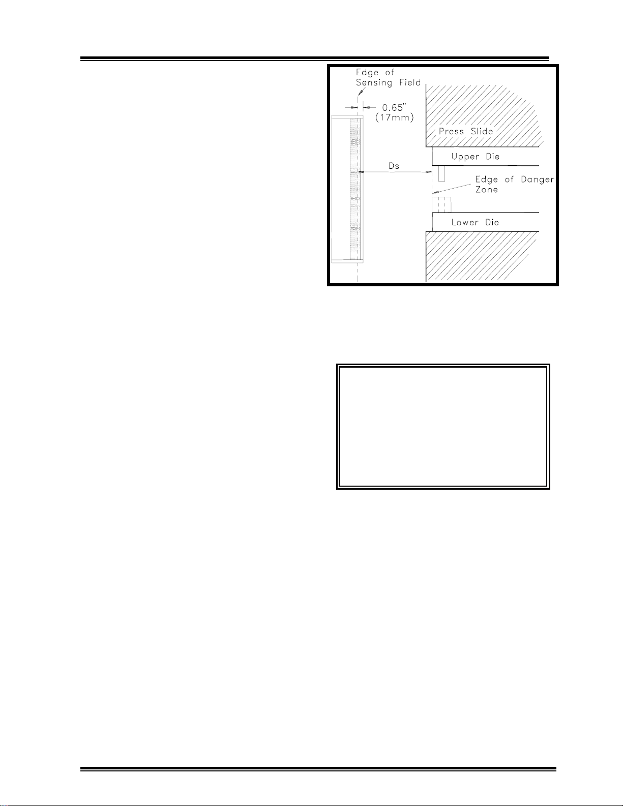
action that poses the hazard. Figure 3.1
depicts one application of the safety
distance.
Figure 3.1: Minimum Safety Distance
WARNING!!
The Link Lite Blac
Max must be installed at a distance
greater than or equal to the safety
distance, D
.Failure to do so can
s
result in serious injury to personnel
because it may be possible to reach
into the hazardous area before the
machine can stop.
The Minimum safety distance in the most
recent ANSI standards is calculated by the
formula:
D
= K (Ts+Tc+Tr+Tbm) + D
S
pf
Where:
D
= the required minimum safety dis-
s
tance
K = 63 in/sec (the average handspeed
constant)
3-2
Page 8

Link Lite Black Max Section 3 - Installation
Ts = the stop time (in seconds) of the
machine measured from the control
output stop signal to the actuator(s)
(valves, etc.) that govern machine
motion till the machine actually
stops.
T
= the response time (in seconds) of the
c
machine control to a stop signal from
the presence sensing device (Black
Max).
NOTE!
If the Link Lite Black Max output
contacts are connected to the emergency
stop circuit of relay controls, most control
designs will cause the Black Max contacts
to directly remove power from the actuators that cause motion without waiting for
other control elements to de-energize. This
means that T
=0 in the case of these
c
controls. If the machine is a part revolution mechanical power press and is
equipped with Link Electric and Safety
Control Co.'s SS501 controls or OmniLink
5000 controls, use T
=0.005 seconds (5
c
milliseconds).
presses. See ANSI B11.1 1988 sections
6.3.2(15) and 4.11 and OSHA's CFR
1910.217 sections (c)(5) and (b)(14).
Where time based monitors with the ability
to set predetermined stop time limits are
provided on machines, T
is determined by
bm
the relation:
T
= Brake Monitor Time Setting-T
bm
s
Where Ts is the actual machine stop time
already described.
NOTE!
On machines where stopping time
performance monitors are not required, a
marginal amount of stopping time to allow
for some normal wear or degradation of
machine stopping mechanisms without
violating safety distance must be substituted for T
. Link recommends that a
bm
value from 10% to 20% of the actual
machine stopping time T
.2T
, be used in place of Tbm. Periodic
s
, i.e. from .1Ts to
s
measurement of actual stopping time must
be performed to prevent stopping time
increase beyond the allowed margin.
T
= the response time of the presence
r
sensing device (Response time for
Black Max units is less than 20 ms see unit label for specific time).
T
= the additional amount of time over
bm
the actual average stopping time
allowed by a brake monitor (stopping performance monitor) to permit
some normal wear of friction brakes
and other components before the
safety distance, Ds, is violated and
the brake monitor prevents
successive strokes.
NOTE!
Stopping performance monitors
(brake monitors) are required on part
revolution presses when light curtains are
used for safeguarding mechanical power
D
= the added safety distance required to
pf
compensate for the possibility that
fingers or hand could penetrate
beyond the plane of the light curtain
sensing field plane before the profile
of the finger/hand/arm is large
enough to be detected by the sensing
field.
All presence sensing devices have a limited
object sensitivity, i.e., it takes a certain size
object to be detected at all points in the
sensing field. Penetration depth depends
on the minimum object sensitivity, M.O.S.,
of the light curtain. M.O.S. is defined as
the smallest object profile that will be
detected at all points in the active sensing
field of the light curtain. The penetration
depth factor, in inches, is described by the
3-3
Page 9

Link Lite Black Max Section 3 - Installation
following formula. Use this formula only
for M.O.S. less than 2.75 inches.
D
= 3.4 (M.O.S. - .276)
pf
Figure 3.2 illustrates the penetration depth
factor in graphical form
Figure 3.2:
penetration depth factor, D
Graphical Representation of
, vs. minimum
pf
object sensitivity.
The minimum object sensitivity in inches
for Link Lite Black Max light curtains is
specified on a label on both transmitter and
receiver enclosures. Standard range units
(to 50') for primary point of operation
guarding have a M.O.S. of .95 inches.
Long range units (to 100') for primary point
of operation guard-ing have a M.O.S. of
1.25 inches. Perimeter guarding models
and supplemental remote extension guarding units may have larger M.O.S.. Always
determine M.O.S. from the labels on the
actual units used. Always verify that both
receiver and transmitter units have the
same M.O.S. stated on their labels before
installing.
PLEASE NOTE!
When individual
channels are to be blanked (turned off) to
allow fixtures or obstructions that extend
into the primary Black Max sensing field,
additional safety distance may be necessary
to account for the increase in M.O.S. due to
blanking. Blanking is possible on Black
Max units with .95" M.O.S. and 1.25"
M.O.S.. Each contiguous (side by side)
channel blanked increases the M.O.S. by
.75".
When the Link Lite Black Max is used on
machines such as power presses, press
brakes, and other machines that have slides
used to impart motion and force to tooling,
the stop time must be measured at approximately midstroke in the closing (hazardous) portion of the stroke. The best
stopping performance of a machine will be
attained when all machine adjustments that
affect stopping time are adjusted within the
machine manufacturer's specifications. It
is the user/employer responsibility to
always maintain mechanisms that affect
stopping time in good repair and adjustment where safety devices like the Black
Max depend on the stopping action of the
machine to protect personnel.
Where a time-base brake monitor is used
on a press or other machine that is to have
a Black Max installed for point-of-operation safeguarding, the stopping time, T
can be determined by use of the brake
monitor. On time base brake monitors
equipped with stop time display, stop the
machine at approximately the mid point of
the die closing portion of the stroke and
read the stopping time displayed. For a
time based brake monitor with no direct
display of stopping time but that has a dial
or other method of setting allowable stop
time, make repeated machine stops near
midstroke, adjusting the time setting each
time until the lowest time setting that
results in the brake monitor allowing a
successive stroke without resetting is
found. This is the stop time, T
, that must
s
be used.
,
s
3-4
Page 10

Link Lite Black Max Section 3 - Installation
When no stopping performance monitor is
used on a machine (you must use one when
required by OSHA or ANSI standards) and
there is no statutory or standards requirement to use a stopping performance
monitor, a stop time measurement device
can be used to measure T
. These are
s
portable devices that usually attach to the
moving slide of the machine to detect when
the slide is stopped after another mechanism of the device gives a stop signal.
3.4
Mounting Considerations and
Requirements
Any installation of Link Lite Black Max
light curtains as a safety component of a
production or other system must include
determination of mounting locations and
orientations of the components of the
Black Max(s) that meet both the safety and
operational requirements of the production
system. General mounting requirements of
various Black Max components are
provided in the following subsections. Any
special requirements must be determined
by the user/employer and must not violate
the general requirements.
Any location and orientation of the
1.
main Black Max transmitter and receiver
units must place the sensing field at a
distance from the hazard greater than or
equal to the safety distance required in
section 3.3 of this manual, i.e. so, that
hands or fingers are D
from the hazard
s
when the sensing field is interrupted by any
part of the body.
Locate the main Black Max transmitter
2.
and receiver units at the same height and
orient at the same angle. The numbers
beside the acrylic lens on the front of the
transmitter unit and the receiver unit
designate the transmitter and sensor
channels. Each transmitter channel number
must be directly across from each similarly
numbered receiver channel. See Figures
3.3.a and 3.3b.
3.4.1
Black Max Main Transmitter and
Receiver Units.
All Black Max installations will have main
transmitter and receiver units that must be
located and oriented to create a primary
sensing field whose function is to detect a
person's hand or other body part and to
provide a stop signal to the machine
control to prevent or stop hazardous
machine action(s) when the hand or other
body part is detected. The main Link Lite
Black Max transmitter and receiver units
may be mounted vertically, horizontally, or
at an angle as long as the following general
requirements are met.
Figure 3.3a:
Front view of transmitter and
receiver units mounted at a common height.
Figure 3.3b:
Top view of transmitter and
receiver units.
3-5
Page 11

Link Lite Black Max Section 3 - Installation
The mounting location or method must
3.
leave access for work pieces, tool changes,
and other operational requirements.
The main transmitter and receiver must
4.
be mounted so that the indicator lights and
warning messages on their enclosure doors
are clearly visible to operators and supervisors and so that the enclosure door can be
opened.
5.
may be mounted directly to the machine, on
brackets attached to the machine, or on floor
stands as long as safety distance and
operational requirements are met.
Mounting brackets must be sturdy to
provide a rigid mounting support that is not
easily knocked out of alignment. When
prefabricated brackets are not provided, the
installer must design and make suitable
mounting brackets.
6.
be installed on two or more machines that
are arranged in a row, alternate the transmitter and receiver units (as to which unit
is mounted on the left and which on the
right side of the machine) on each adjacent
machine as shown in Figure 3.4 to reduce
the possibility of crosstalk. Crosstalk
occurs when light pulses from transmitter
unit mounted on one machine are "seen"
not only by the intended receiver unit, but
also by receiver units on other machines.
For many infrared light curtains on the
market today this creates a danger to
operators because their receiver units
accept crosstalk pulses just as they accept
pulses from the correct transmitter. An
operator may have a hand or arm in a light
curtain sensing field, blocking light pulses
from the transmitter on his machine, and a
transmitter on another machine can pass
over or under his arm, "fooling" the receiver into not providing a stop signal to
The main transmitter and receiver
When Black Max light curtains are to
the machine control as required. The
Black Max is designed to detect crosstalk
from other light curtains and to provide a
stop signal if it occurs. It is important to
install Black Max light curtains in such a
manner as to avoid nuisance machine stops
caused by crosstalk.
Figure 3.4:
crosstalk.
The scheme shown in Figure 3.4 should
also be followed when infrared light
curtains other than the Black Max are used
on adjacent machines.
Mount the Black Max main transmitter
7.
and receiver units on the rubber shock
mounts provided in the shipment box using
one of the two mounting methods shown in
Figure 3.5.
Figure 3.5:
Mounting scheme to minimize
Use of rubber shock mounts.
3-6
Page 12
Link Lite Black Max Section 3 - Installation
p
The Black Max transmitter and receiver
8.
each have four mounting holes, two in each
end mounting flange. See Figure ---, page
---, for mounting hole dimensions and
patterns for various length units.
3.4.2 Black Max Remote Segment
Transmitter and Receiver Units.
Black Max remote segment transmitter and
receiver units are housed in separate
enclosures from the main Black Max
transmitter and receiver. When electrically
connected to the main transmitter and receiver units, they provide additional
channels of emitters and receptors which are
sequenced by the logic electronics in the
main transmitter and receiver, respectively. Remote segment units will be part
of the installation only when the
user/employer has purchased them as
components of the safety system to supplement the protection provided by the main
transmitter and receiver units.
Since the remote segments are in separate
enclosures from the main Black Max units,
they can be used to create "L" shaped or
other sensing field shapes when combined
with the main transmitter and receiver
units. When safety distance requirements,
machine configuration, or operational
requirements place the primary sensing
field between the main transmitter and
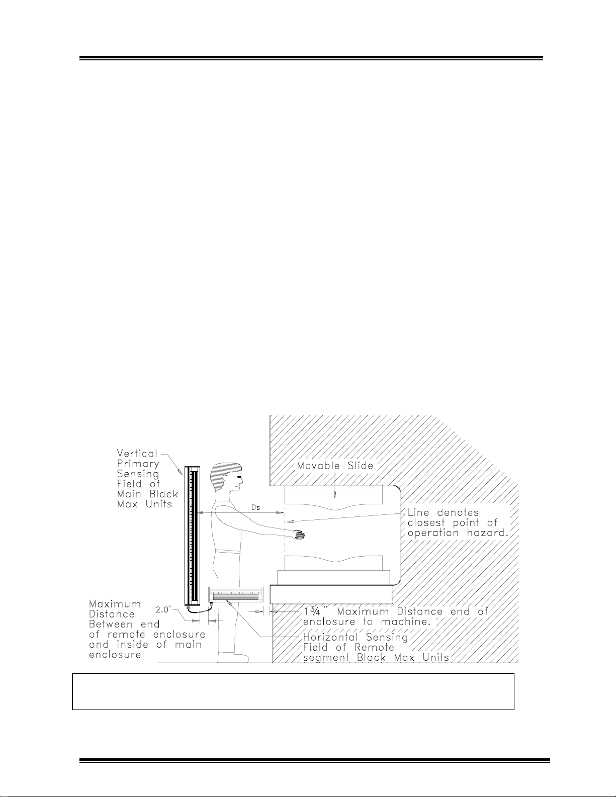
receiver at a location that allows a person
to pass completely through the primary
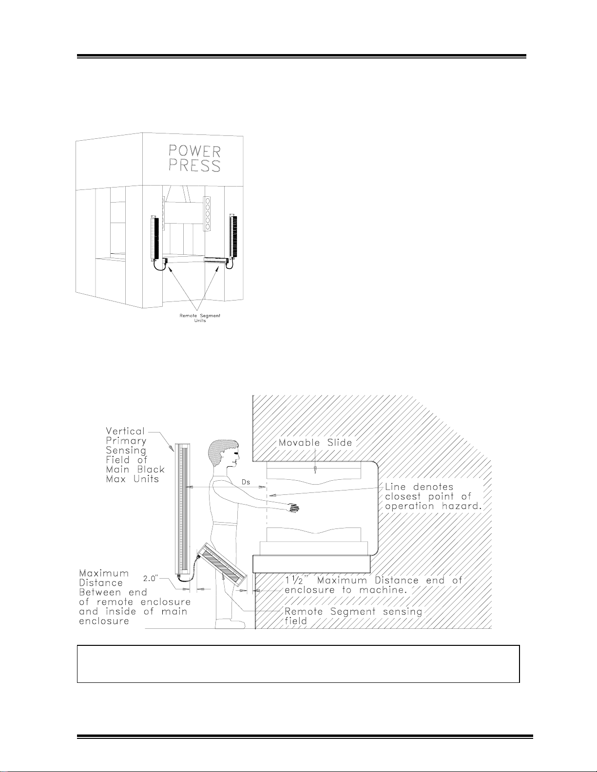
sensing field toward the hazard, horizontally oriented remote segment Black Max
units can be used to detect a person standing inside the sensing field as shown in
Figure 3.6.
Figure 3.6:
erson inside the main sensing field.
Horizontally mounted remote segment Black Max units to detect a
3-7
Page 13
Link Lite Black Max Section 3 - Installation
Figure 3.7. Shows remote segment units
mounted on a straight side press with
columns extended beyond the bed and
slide.
Figure 3.7:
units mounted between columns of straight
side power press to detect a person standing
inside the primary sensing field.
Remote segment Black Max
The mounting requirements for remote
segment Black Max units are generally the
same as for main transmitter and receiver
units except that when used for
supplemental guarding between the main
sensing field and the hazard, there is no
safety distance, D
location of remote segment units.
NOTE!
any manner intended to extend and be part
of the main sensing field, safety distance
requirements will then apply to the remote
segment units.
If remote segment units are used in
, requirement for the
s
Figure 3.8:
between the primary sensing field and the hazard.
Remote segment Black Max units oriented at an angle to sense a person
3-8
Page 14
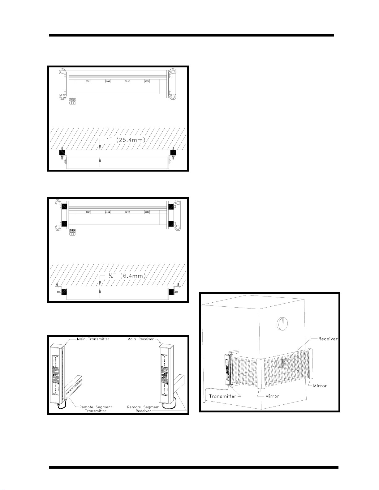
Link Lite Black Max Section 3 - Installation
Also, the mounting arrangement is somewhat different for the remote segement units
as shown in Figures 3.9a and 3.9b.
Figure 3.9a:
Black Max unit mounting.
Example of remote segment
Black Max remote segment transmitter and
receiver units must always be mounted on
the same side of the machine, respectively,
as the main transmitter and receiver units as
shown in Figure 3.10
3.4.3 Use of Mirrors for Multi-Sided
Point of Operation or Perimeter
Safeguarding Applications
In some safeguarding applications mirrors
may be used to "bend" the sensing field
provided by main Black Max units to
provide two or more sided safeguarding for
point of operation or perimeter safeguarding. Mirrors for this purpose can be
purchased from Link Systems. Since even
the finest quality mirrors do not reflect
100% of incident light and some diffusion
of light occurs, the maximum sensing field
distance between transmitter and receiver
will be reduced by about 10% per mirror
used. Figure 3.11 illustrates a three sided
point of operation safeguarding application.
Figure 3.9b:
Black Max unit mounting.
Figure 3.10:
transmitter and receiver units on the same
respective sides.
Alternate remote segment
Mount main and remote
NOTE!
maintained on all sides of sensing field.
Figure 3.11:
of operation guarding on C frame press.
Safety Distance, D
Example of three sided point
, must be
s
3-9
Page 15
Link Lite Black Max Section 3 - Installation
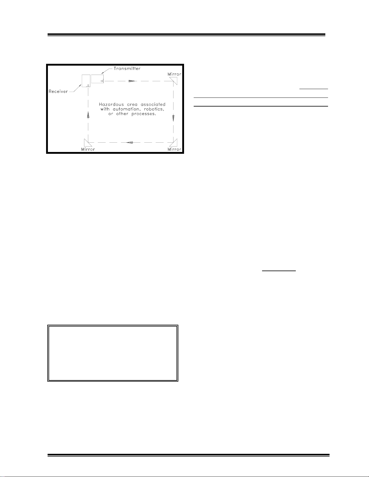
g
Figure 3.12 Illustrates a four sided perimeter guarding application.
Figure 3.12:
perimeter guarding application.
3.5 Electrical Wiring to I nterface Link
Lite Black Max Units to Power and
the Machine Control.
When all Link Lite Black Max transmitter
and receiver units have been mounted, you
are ready to make electrical connections to
interface the Black Max(s) to power and
the machine control. Also, if remote
segment Black Max units are used, you
must connect the remote segment transmitter unit to the main transmitter unit and the
remote segment receiver unit to the main
receiver unit with the cables provided.
Top view of four sided
accommodate a 1/2" conduit fitting. Run a
1/2" conduit from the machine control
enclosure to each main Black Max transmitter unit. Similarly, run a 1/2" conduit
from the machine control enclosure to each
main Black Max receiver unit.
required for the transmitter and receiver
should be pulled through the 1/2" conduit.
Use of flexible conduit with integral armor
and ground wire, such as Seal Tite, is
preferable. When such flexible conduit is
used, it is also desirable to route it in such
a way as to leave slack that will allow the
Black Max units to be moved further away
from the machine if future setups necessitate moving the transmitter(s) and receiver(s) to meet safety distance requirements.
There are also two holes that are sized for
3/4" fittings, one in both ends of the main
transmitter and receiver units. These holes
are closed with screw in type plugs. They
should only be used for cable connections
between main transmitter and receiver
units and remote segment receiver and
transmitter units.
plugged openings for conduit between the
main Black Max units and the control
enclosure. Use the open 7/8" hole only.
DO NOT
All wires
use the
WARNING!
shock hazards lock all power to the
machine off before beginning the
wiring procedures for the Link Lite
Black Max. In the U.S., follow OSHA
Lockout re
3.5.1 Conduit Requirement s
The main Black Max transmitter and
receiver units both have a 7/8" hole to
To prevent electrical
ulations.
3.5.2 Power Connections
Both the transmitter and receiver units of
the Black Max must be supplied with 115
VAC (Nominal) power. Generally, this
power should be supplied from a transformer with 115 VAC secondary in the
machine control. Pull a "hot" wire, a
neutral wire, and a ground wire through the
conduit from the control enclosure to the
Black Max main transmitter unit. Refer to
Figure 3.13 for the location of the combination three connection power terminal and
plug in connector.
3-10
Page 16

Link Lite Black Max Section 3 - Installation
Figure 3.13:
Location of transmitter power connector.
3-11
Page 17

Link Lite Black Max Section 3 - Installation
g
Unplug the terminal/connector from its
socket and turn the three wire clamp
screws counterclockwise so that the power
wires can be inserted into the wire clamping slots. Strip the three power wires about
1/4" from their ends, insert them into the
wire clamping slots, and tighten the
clamping screws in the following order.
"Hot"
Neutral
Ground
When finished connecting the wires, plug
the terminal/connector back into its socket.
Three power wires must also be pulled
through the conduit from the machine
control to the main Black Max unit. The
location of the three connection power
terminal/connector is shown in Figure 3.14
for the receiver unit. Connect the power
wires to the receiver to the power terminal/connector by following the same
procedures outlined for transmitter power
connections.
3.5.3
Link Lite Black Max(s) must be wired into
the machine control circuit in such a
manner that their stop signal to the control
results in the control immediately initiating
machine stopping action.
Control Connections
WARNING!
Link Lite Black Max(s) to the machine
control can cause the Black Max to be
ineffective as a safety device with
possible consequent injury to personnel
by the machine hazard intended to be
safe
uarded.
wire connects to
terminal marked L1
wire connects to terminal
marked L2
wire connects to terminal
marked GND
Improper connection of
All control wiring connections to the Link
Lite Black Max are made to the eight
position terminal/connector located on the
relay board in the main Black Max receiver
enclosure, accessible by opening the door
to the receiver enclosure as shown in
Figure 3.14. Run wires through the 1/2"
flexible conduit from the machine control
enclosure to the main Black Max receiver
unit to interconnect the light curtain to the
control.
Two normally open (N.O.) and one normally closed (N.C.) contact paths are
supplied in the Link Lite Black Max
receiver unit for interconnection to
machine control circuits. Two separate
relay contacts whose operation is checked
by Black Max logic circuits are used in
each path as shown in Figure 3.14. The
interconnection of the Black Max(s) to the
control circuit depends on the design and
configuration of the machine control
circuit. When the Black Max is used with
a machine control supplied by Link
Systems, schematics will be provided that
show the connections that must be made
between the Black Max light curtain and
the control. Wire as shown in the schematic. Do not deviate from the schematic
unless Link gives written approval of an
alternative wiring scheme.
When interconnecting Black Max units to
controls not supplied by Link, at least one
of the normally open contact paths must be
used to provide the stop signal to the
machine control in such a manner that the
control immediately initiates machine
stopping action. In some cases use of both
normally open contact paths of the Black
Max may be necessary. The normally
closed contact path between terminals 3
and 4 must never be used to provide the
stop signal to the press control. Link
provides these terminals for use in addition
to normally open contact
3-12
Page 18

Link Lite Black Max Section 3 - Installation
Figure 3.14:
Power and relay connections for Black Max receiver.
3-13
Page 19

Link Lite Black Max Section 3 - Installation
p
paths in special interfaces between the
Black Max and the machine controls
designed by Link Systems.
WARNING!
closed contact path only to provide a
stop signal to the machine control. A
loose connection or broken wire would
result in no stop signal being supplied
to the control by the Black Max even
though the Black Max itself was
operating properly.
Link Systems will evaluate existing
machine controls as to their suitability for
use with the Link Lite Black Max upon
customer request and provision of schematics, and will mark schematics for interconnection with the Black Max when such
controls are suitable for use with the Black
Max.
WARNING!
provides machine controls or marks
existing machine control schematics for
interconnection with Black Max units,
always wire as shown by Link on
schematics. Improper connection of
Black Max units to the machine control
may result in failure of the machine to
stop even though the Black Max
component is functioning properly with
possible serious injury or death to
ersonnel.
Never use the normally
When Link Systems
mechanical power presses, hydraulic power
presses, power press brakes, etc., OSHA
and ANSI allow presence sensing devices
such as the Link Lite Black Max to be
interconnected or interfaced with the
machine control so that the protective
function is bypassed (muted) during the
non-hazardous portion of the stroking cycle
only. Never simply use unmonitored limit
switch contacts to mute the Black Max in
the non-hazardous part of a machine cycle.
Interfacing to maintain "control reliability"
in the event of a component fault in the
muting circuit is necessary.
Some machine controls are designed to
require cycling of light curtain output
relays on each cycle of the machine even if
the sensing field is not interrupted.
Terminals 1 and 2 on the eight position
terminal/connector provide an input to
cycle the output relays. To activate the
relay cycle circuit a jumper must be removed on the receiver logic board in the
receiver unit. See Figure 3.15. When the
jumper is removed, a voltage must be
supplied between terminals 1 and 2 to
energize the output relays in each receiver
unit (but only when the Black Max transmitter and receiver are properly aligned
and no obstruction is in the sensing field).
Switching this voltage off at least 35
milliseconds will cause relays LC1 and
LC2 to de-energize. If both relays switch
off and the voltage is switched back onto
terminals 1 and 2, the relays will again
energize. This relay cycle is normally done
during the non-hazardous portion of the
machine stroke when the Black Max is
muted to avoid stopping the machine when
the relays are de-energized.
In some cases, Link Systems may have to
provide an interface circuit to accomplish
proper interconnection of the Link Lite
Black Max with a customers existing
control circuit.
On linearly stroking machines such as
As shipped, a voltage of 12VDC to 30VDC
may be used for the relay cycle input to
terminals 1 and 2 when the jumper is
removed. Removing jumpers J2 and J3 on
the receiver Relay Board as
3-14
Page 20

Link Lite Black Max Section 3 - Installation
y
Figure 3.15:
Location of rela
check con-figuration jumpers.
3-15
Page 21

Link Lite Black Max Section 3 - Installation
g
shown in Figure 3.15 will configure the
relay cycle circuit for 115VAC input
voltage between terminals 1 and 2.
Some machines use programmable logic
controllers (PLCs) as the machine control.
The Black Max must never be connected to
only the inputs of a single PLC controller.
Always contact Link before
Lite Black Max as a protective device on a
machine with a PLC control. Most PLC
controls do not meet OSHA's control
reliability requirement for use of a presence
sensing device.
WARNING!
Black Max on a machine controlled by
a PLC without first consulting Link
Systems as to whether the Black Max
should be used and how it should be
connected to the control. Failure of the
PLC control could cause the machine to
fail to stop even though the Black Max
is functioning properly if the control
system is not designed to provide a stop
signal to the machine in the event of
a component failure or program fault.
Serious injury or death may result from
the hazard intended to be safe
3.5.4
Connections between main Black Max
transmitter and receiver units and remote
segment units are accomplished by a cable
that terminates inside the main and remote
units in a ribbon cable plug-in connector.
The cable enters each unit enclosure
through a water and oil tight screw on
fitting. See Figures 3.16 and 3.17. The
remote segment unit may be connected to
either end of the main unit by removing the
Connections Between Main Black
Max Units and Remote Segments
Units
Never use a Link Lite
using a Link
uarded.
screw-in plug in the large hole in the end
cap, running the ribbon cable through the
hole, and screwing the cable fitting into the
hole. Always leave the screw-in plug in
place on the unused end of the main
transmitter or receiver unit to retain the
NEMA 4 performance of the enclosure. In
some cases, two remote segment units may
be used, one off of either end of the main
transmitter or receiver enclosure. This is
illustrated in Figure 3.18.
3.6
Setting The Black Max Transmit-
ter Power Level
After mounting and electrically connecting
the Black Max transmitter and receiver
units, the transmitter power must be set for
the separation distance between the transmitter and receiver. Using more power
than necessary to transmit between transmitter and receiver is undesirable because
of the possibility that the excess light
energy can be detected by other Black Max
receiver units on other machines. This
cross talk would result in nuisance stops on
the other machines. Also, the life of the
infrared light emitting diodes in the transmitter is somewhat dependent on power
level. These components will have prolonged life at lower power levels.
To set the transmitter power level, open the
door of the main transmitter enclosure,
locate the small 4 position DIP switch on
the outside edge of the transmitter logic
board, and adjust the switch positions
according to the power level table located
on the inside of the transmitter door. The
location of the 4 position switch and power
level table are shown in figure 3.19.
Always adjust the power level correctly for
the separation distance between the Black
Max transmitter and receiver.
3-16
Page 22

Link Lite Black Max Section 3 - Installation
g
Figure 3.16:
Use of remote se
ment at bottom of main transmitter.
3-17
Page 23

Link Lite Black Max Section 3 - Installation
Figure 3.17:
Remote segment unit used at top of main transmitter.
3-18
Page 24

Link Lite Black Max Section 3 - Installation
g
Figure 3.18:
Use of two remote se
ment units with main transmitter.
3-19
Page 25

Link Lite Black Max Section 3 - Installation
p
Figure 3.19
: Location of the transmitter
ower level switch and power level table.
3-20
Page 26

Link Lite Black Max Section 3 - Installation
NOTE!
Max light curtain is designed to supply a
stop signal when far too much light is
received from the transmitter.
3.7
After setting the proper transmitter power
level, make sure that both the Black Max
transmitter and receiver enclosure doors are
closed and screwed shut. If the mounting
instructions in section 3.4 have been correctly followed, the acrylic lens on the
transmitter and receiver units should face
each other, the channel numbers beside the
acrylic lens on the transmitter and receiver
units should be directly across from each
other, the receiver and transmitter should be
mounted at the same height from the floor
and in the same plane. Final alignment must
now be done. Each transmitter channel of
the Black Max sends out a focused cone of
infrared light at a diverging angle rather like
a sharply focused flashlight. This beam of
light from a transmitter channel must fall
upon the similarly numbered receiver
channel. Also, each receiver channel has a
lens to provide a limited cone of view. Each
receiver channel must "look" at the
transmitter channel with similar number.
Figures 3.20 and 3.21 illustrate correct and
incorrect alignment from front and top
views, respectively.
The receiver unit of the Black
Aligning The Black M ax Trans-
mitter(s) and Receiver(s)
Figure 3.20b:
receiver in alignment from front view.
Figure 3.21a:
receiver out of alignment from top view.
Black Max transmitter and
Black Max transmitter and
Figure 3.20a:
receiver out of alignment from front view.
Black Max transmitter and
Figure 3.21b:
receiver in of alignment from top view.
Figure 3.22 illustrates alignment of transmitter and receiver from the side view. If
Black Max units are not aligned properly,
the receiver will not see the transmitter
light, and a continuous stop signal will be
3-21
Black Max transmitter and
Page 27

Link Lite Black Max Section 3 - Installation
sent by the Black Max receiver unit to the
machine control.
Figure 3.22a:
of alignment from side view.
Transmitter and receiver out
receiver units. Verify that power is on the
transmitter by observing that the green
"POWER" LED in the front center of the
transmitter unit is on. Verify that power is
on the receiver by observing that either the
green "CLEAR" LEDS or the red "STOP
SIGNAL" LEDS in the front center of the
receiver unit are on. Don't start the
machine for this alignment procedure.
Leave all motors off.
Check to make sure that no grease or
2.
dirt covers the red acrylic lens in the front
of the transmitter and receiver units and
that no obstruction is between the transmitter and receiver. Also, check the front of
the main receiver unit to make sure that the
amber colored "NO BLANKING" light is
on and that the RUN-PROGRAM -SELECT switch is in the "RUN" position. If
not, use the key for the RUN PROGRAM - SELECT switch to obtain
these conditions.
Figure 3.22b:
alignment from side view.
To align the Black Max transmitter and
receiver units perform the following steps.
Turn on the main disconnect switch to
1.
the machine control to supply power to the
Link Lite Black Max transmitter and
Transmitter and receiver in
Observe the green "CLEAR" and red
3.
"STOP SIGNAL" lights on the door of the
main receiver unit. If the transmitter and
receiver are aligned to where some part of
the cone of light from each emitter in the
transmitter falls upon its similarly numbered phototransitor channel on the receiver and, if the receiver is aligned well
enough that some sector of its cone of
vision can see the light from the emitter,
the "CLEAR" lights will be on. If not, the
"STOP SIGNAL" lights will be on. Even if
the "CLEAR" lights are on, indicating at
least rough alignment, perform the following steps to achieve best alignment. Best
alignment results when the cone of transmitted light and the cone of receiver vision
are centered on each other.
The L shaped mounting "ears" for the
4.
Link Lite Black Max units are designed to
allow easy alignment if the mounting
3-22
Page 28

Link Lite Black Max Section 3 - Installation
j
brackets (or surface) to which the transmitter and receiver are to be mounted are in
reasonable alignment. The two mounting
holes in the "ears" that bolt to the mounting
surface are slotted to allow the transmitter
and receiver units to be aligned lengthwise
as shown in Figure 3.20b. The front
mounting hole on the section of the
mounting ear that attaches to the transmitter and receiver unit is slotted (the rear hole
is not) to allow pivoting motion to align the
transmitter and receiver in the direction
shown in Figure 3.21b. To achieve best
alignment, first loosen the bolts on the
mounting ears of transmitter and receiver
units that attach the ears to the mounting
brackets or other mounting surface and use
a carpenters level to get them plumb as
shown in Figure 3.20b. When plumb,
tighten mounting ear bolts to the bracket or
surface.
connect the mounting ears to the transmitter unit to lock the transmitter into angular
alignment.
Loosen the bolts that connect the
7.
mounting ears to the receiver unit and
repeat the procedure of step 6 with the
receiver to bring the receiver into angular
alignment.
NOTE
that have remote segment units, first align
main receiver and transmitter units and
then remote segment receiver and transmitter units. Until both main and remote
segment units are roughly aligned, the
green "CLEAR" lights on the main receiver
door won't come on.
3.8 Functional Checkout of the Link
! When aligning Black Max units
Lite Black Max Installation and
Machine.
Now loosen the mounting ear bolts that
5.
connect the mounting ears to the transmitter and receiver units and pivot transmitter
and receiver back and forth until the green
"CLEAR" light comes on the door of the
receiver unit. Tighten the bolts that hold
the mounting ears to the receiver unit only,
making certain that the green "CLEAR"
light stays on as you do so.
Pivot the transmitter clockwise just till
6.
one or more of the red LEDS behind the
acrylic lens on the front of the receiver
come on, indicating that these channels
have lost alignment. Then pivot the
transmitter counterclockwise. The red
channel LEDS should first turn off as the
transmitter is rotated back into alignment,
then turn back on as alignment is lost in the
counterclockwise direction. Again pivot
the transmitter clockwise until the transmitter is located at an angle halfway between
the clockwise and counterclockwise loss of
alignment angles. Tighten the bolts that
When the installation steps described in
sections 3.3 through 3.7 have been successfully completed, a functional checkout of
the operation of the machine and the Link
Lite Black Max(s) must be performed
before placing the machine into production, or before beginning installation of
supplementary barriers if necessary.
WARNING!
of the Link Lite Black Max Installation
and the machine on which it is installed
must be performed to verify that the
Black Max is wired into the machine
control to provide on immediate
initiation of stopping action and that
the machine is functioning correctly.
Serious injury or death can result from
hazardous machine action if there are
installation errors or machine
misad
ustments or malfunctions.
The functional checkout
3-23
Page 29

Link Lite Black Max Section 3 - Installation
Perform the following checkout steps:
Turn on power to the Link Lite Black
1.
Max units by turning the main disconnect
to the machine control to the on position.
Do not turn on machine motor(s). Verify
that there are no obstructions between
transmitter and receiver units.
Look at the door of the main Black Max
2.
receiver unit and verify that the green
"CLEAR" lights are on, that the amber "NO
BLANKING" light is on, and that the RUN
- PROGRAM - SELECT switch is in the
RUN position. If not, use the key for the
RUN - PROGRAM -SELECT switch to
obtain these conditions.
Both the main transmitter and receiver
3.
units have a label that states their minimum
object sensitivity (M.O.S.). Check these
labels to verify that both transmitter and
receiver have the same M.O.S.. If a
different M.O.S. is stated on the receiver
and transmitter, a different model number
transmitter and receiver have inadvertently
been installed. find the transmitter or
receiver that corresponds with the intended
model number and exchange to correct this
situation. When you have determined the
M.O.S. of the installed units, obtain a test
bar or strip that has a width equal to the
M.O.S. of the installed Black Max system.
NOTE!
used as supplementary safeguarding, the
M.O.S. of these units will usually be
different than the main units. Check the
labels on these units for M.O.S..
Place the test bar or strip obtained in
4.
item 3 immediately in front of the top
channel of the main receiver unit and
slowly lower the bar or strip through the
sensing field to the bottom channel,
observing to confirm that each channel
If remote segment units are also
indicator light behind the acrylic receiver
lens lights as its channel is blocked, and
that the red "STOP SIGNAL" lights on the
receiver door stay continuously on as the
bar or strip is lowered from top to bottom.
Repeat step 4 with the bar or strip
5.
placed immediately next to the main
transmitter unit and lowered from top to
bottom.
Repeat step 4 with the bar or strip
6.
halfway between the transmitter and
receiver units and lowered from top to
bottom.
If remote segment transmitter and
7.
receiver units are installed, block each
channel of the remote segment unit and
confirm that its channel indicator light
located behind the acrylic lens on the
remote segment receiver unit comes on and
that the red "STOP SIGNAL" lights on the
door of the receiver come on.
If any of the results in the test per-
8.
formed in the preceding steps are not as
specified, go to the troubleshooting section
of this manual or contact Link Systems to
correct the problem. Do not start the
machine until the problem is corrected. If
the preceding tests were successful, start
the machine and, with no obstruction
between the Black Max transmitter and
receiver units operate the machine in all
modes to confirm normal operation. If the
green "CLEAR" lights on the main receiver
unit door are on but the machine won't
operate, incorrect wiring from the Black
Max to the machine control is indicated. If
the machine operates properly proceed to
the next step.
3-24
Page 30

Link Lite Black Max Section 3 - Installation
Take the test bar or strip used in steps 4
9.
through 6 and insert it into the sensing field
between the transmitter and receiver. The
machine stopping action should immediately be initiated when the sensing field is
interrupted. An exception to this occurs
when the Black Max is muted during a part
of a machine cycle that is not hazardous.
The interruption of the sensing field should
then only stop the machine action during
the hazardous portion of the cycle check to
see that the machine does stop in all
hazardous parts of the stroke. Repeat this
test several times, making sure that the
machine stops properly and that the safety
distance requirement of section 3.3 is met
for the stopping time encountered under
the conditions of this test. If the machine
that the Black max is installed on has
multiple operating modes (such as Inch,
Single Stroke, and Continuous on a
mechanical power press) repeat this test in
all modes to verify the intended stopping
action. If the stopping mechanisms of the
machine seem to be working improperly or
erratically, notify the user/employer and
request that a maintenance person qualified
to adjust or repair the stopping mechanisms
be assigned to do so. Don't proceed to the
next step until the problem is corrected.
If all requirements of the preceding
10.
checkout steps are met, the installation of
the Link Lite Black Max components of the
safety system is complete. If the installer(s) of the Black Max components has
been contracted or assigned the responsibility to provide any other necessary
supplemental guarding components of the
safety system, proceed to section 3.9. If
someone else is to install other components
of the safety system that may be required,
the Black Max installer(s) should notify the
user/employer that his phase of the
installation is complete.
3.9
Supplemental Guard Installation
Requirements
Although a safety system design for an
industrial machine that uses only light
curtains, such as the Link Lite Black Max
units in addition to the machine components involved in stopping hazardous
action can often be accomplished, it is
sometimes necessary to make and install
barriers to supplement the safeguarding
function intended to be performed by the
Black Max sensing field(s) to comply with
OSHA and ANSI standards. Often, the
requirement and physical configuration for
barriers can only be determined after the
Black Max installation. The safety distance requirement, configuration of the
machine, size, and location of the light
curtain and tooling can all be factors which
affect the specific application. There are
two areas of concern that must be considered when determining whether supplemental guards or barriers are required.
Any light curtain, including the Black
1.
Max, only protects people who reach
through its sensing field as they approach
the hazard to be safeguarded. Therefore,
once the Black Max units have been
installed, if it is possible to enter the
hazardous area over, under, or around the
Black Max(s) sensing field(s) from any
normal position associated with the tasks
of operators or other personnel, barriers
must be installed to cause the only path to
the hazard to be through the Black Max(s)
sensing field(s).
The Black Max will not protect people
2.
if the required safety distance discussed in
section 3.3 places the main transmitter and
receiver far enough away from the hazard
that a person can assume any normal
position between the Black Max sensing
field and the hazard, i.e., so that he can
3-25
Page 31

Link Lite Black Max Section 3 - Installation
g
have a body part in the hazardous area
without being detected. If remote segment
Black Max units are not used to detect a
person standing between the primary
sensing field created by the main transmitter and receiver and the hazard (see section
3.4.2), then barriers must be installed to
keep someone from passing completely
through the Black Max sensing field
toward the hazard.
WARNING!
supplemental barriers, when required,
may result in serious injury to someone
reaching the hazard through an opening
or area not sensed by the Black Max
li
ht curtain(s).
Barriers installed to prevent people from
reaching over, under, or around the Black
Max(s) sensing field(s) must meet several
OSHA construction requirements. These
are:
The guard should prevent reaching
1.
over, under, or around the guard and into
Failure to install
the point of operation, except through the
Black Max(s) sensing field(s).
Openings in the guard must meet the
2.
requirements of OSHA Table 0-10.
The barrier must be installed so that it
3.
doesn't create hazards (such as pinch
points) between the guard and moving
machine parts.
Unless the barrier is interlocked with
4.
the machine control to prevent hazardous
action of the machine when it is not in
place, it should use fasteners that require
tools to remove.
Barriers to prevent someone from assuming
a position between a Black Max sensing
field and the hazard without being detected
must be installed to prevent a persons body
from passing completely through the Black
Max sensing field as he approaches the
hazard.
Figures 3.23 through 3.26 give general
illustrations of the use of supplemental
barriers.
Table 0-10
Distance of Opening Maximum Width
to Nearest Hazard of Opening
½” to 1 ½” ¼”
1 ½” to 2 ½” 3/8”
2 ½” to 3 ½” ½”
3 ½” to 5 ½” 5/8”
5 ½” to 6 ½” ¾”
6 ½” to 7 ½” 7/8”
7 ½” to 12 ½” 1 ¼”
12 ½” to 15 ½” 1 ½”
15 ½” to 17 ½” 1 7/8”
17 ½” to 31 ½” 2 1/8”
3-26
Page 32

Link Lite Black Max Section 3 - Installation
Figure 3.23:
the top of a Black Max sensing field or through the openings of a C frame machine.
Illustration of barriers installed to prevent someone from reaching over
3-27
Page 33

Link Lite Black Max Section 3 - Installation
g
p
p
Figure 3.24:
between li
Figure 3.25:
ht curtain and hazard.
A Black Max with supplemental barrier to prevent standing
Exam
le of a Black Max on a press brake with supplemental barriers.
Figure 3.26:
rotect inside primary sensing field, and barriers to prevent entry from the side.
Use of Black Max remote segment units in the horizontal position to
3-28
Page 34

Link Lite Black Max Section 4 - Operating Instructions
Link Lite Black Max light curtain
4 OPERATING INSTRUCTIONS,
REQUIREMENTS, AND PRECAUTIONS
IMPORTANT!
operators, supervisors, maintenance
personnel, and other persons associated
with the care and use of machines or
production systems using Link Lite Black
Max light curtains as safety components
must read (or be provided with the knowledge of) the material in this
Instructions, Requirements and Precautions
section to enhance safety to the fullest
possible extent. OSHA and ANSI standards make it the employer's responsibility
to train all employees associated with the
setup, operation, and maintenance of the
machine, and to provide supervision to
ensure that employees follow proper setup
and operation procedures.
All
setup personnel,
Operating
1.
presence sensing devices are designed and
manufactured to comply with OSHA and
ANSI standards for construction of point of
operation devices. Properly installed,
located, adjusted and used presence
sensing devices enhance personnel safety
by preventing normal initiation of hazardous machine action or by stopping normal
hazardous action in progress if the operator's (or other's) hand or other body part are
in the sensing field (the plane directly
between the Black Max transmitter and
receiver units as shown in Figure 4.1).
4.1 Safeguarding System L imitations
and Requirements
Link Lite Black Max light curtains are not
the safety system, but rather are a component of the machine safety system. Light
curtains send a stop signal to the control of
a machine when someone of something
blocks their sensing field light. They
depend on other electrical, pneumatic,
mechanical, and/or hydraulic components
of the machine drive system to actually
stop hazardous action when you are in the
sensing field. In some cases, supplemental
barriers or safety devices may be required
in addition to light curtains to protect you
from the machine or production system
hazard(s). Light curtains must be properly
installed, located, and used in conjunction
with any other necessary safety components to protect you, in accordance with the
following requirements.
Figure 4.1:
location between main Black Max
transmitter and receiver units when no
blanking is used.
WARNING!
device, including the Link-Lite Black
Max, will protect you from abnormal
hazardous machine action(s) caused by
failure, wear, or misadjustment of
mechanical, hydraulic, pneumatic, or
electrical components of the machine
upon which it is installed. Serious
injury or death may result from such
failures.
Proper machine preventative maintenance
must be performed to reduce the risk of
accidents that result from failure, wear, or
misadjustment of machine components.
Illustration of sensing field
No presence sensing
4-1
Page 35

Link Lite Black Max Section 4 - Operating Instructions
p
g
The main Black Max sensing field must
2.
be located far enough away from the
hazardous area that machine action will be
stopped before a persons hand that passes
through the light curtain sensing field can
reach the closest hazard. This safety
distance is required by both OSHA and
ANSI. The minimum safety distance, DS, is
determined by a formula which is explained in section 3.3 of the installation
section of this manual.
It must never be assumed that the original
installation of a Black Max light curtain will
always result in maintaining D
setups and under all operating conditions.
For several reasons, safety distance must be
verified for each setup under actual
operating conditions.
for all
S
Figure 4.2:
Illustration of Minimum Safety
Distance Measurement
First, D
depends on the stopping time, TS,
S
of the machine, which can vary depending
on many factors, including position in
stroke, cycle rate, air or hydraulic pressure,
speed of moving parts (stroking speed),
temperature of hydraulic fluid, weight of
tooling attached to moving machine parts,
and counterbalance adjustment. On
machines equipped with friction clutches
and brakes, clutch and brake wear over a
period of time can cause the stopping time
to increase. Some hydraulically operated
machines have adjustments that can affect
stopping time.
Second, the size and location of the tooling
used in a machine often varies for each
machine setup, bringing the hazardous
point of operation closer or farther away
from the Black Max sensing field on
different setups and thus affecting D
. For
S
this reason the person(s) assigned to set the
machine up for different production jobs
must verify the safety distance for each
setup. See Figure 4.2
WARNING!
The Link Lite Black Max
sensing field must be located at a
distance greater than or equal to the
safety distance, D
. Failure to do so
S
can result in serious injury to personnel
because it is possible to reach into the
hazardous area before the machine can
sto
.
Light curtains, including the Black
3.
Max, only protect people who reach
through their sensing field as they approach the hazard to be safeguarded.
WARNING!
The Black Max light
curtain will not protect you if you
reach over, under, or around its sensing
field and into the hazard. Serious
injury may result if you can enter the
hazard other than through the Black
Max sensin
field.
Depending on the safety system design and
the machine or production system configuration, supplemental barriers may be
4-2
Page 36

Link Lite Black Max Section 4 - Operating Instructions
p
required to prevent someone from reaching
the hazardous area from any normal
position associated with the employer
defined tasks of operators or other personnel other than through the Black Max
sensing field. These barriers must be
provided and used
supplement the Black Max safeguarding
component.
. The required safety distance of item 2
4
may place the main Black Max sensing
field far enough away from the hazard that
a person can assume a normal working
position between the sensing field and the
hazard. A person in such a position can
reach into, or enter into, the hazardous area
without being detected by the main Black
Max sensing field, and the Black Max will
provide no protection if hazardous machine
action is started.
A physical barrier to prevent persons from
standing inside the main Black Max
sensing field or Black Max remote extension units oriented horizontally and
extending outward from the machine to
detect persons inside the main sensing field
and prevent normal machine action must be
used if every person operating or helping
with the production system doesn't have his
own set of active operator controls, located
on the other side of the main Black Max
sensing field, from the hazard. These
operator controls must be designed to be
operated concurrently with all other
operator controls to initiate machine
action.
WARNING!
Max will not protect a person in a
position between the sensing field and
the hazard. Serious injury or death
may be inflicted by the hazard if
machine or production system action is
started while a person is in such a
position.
when necessary to
The Link Lite Black
Any task associated with a machine or
5.
production system using a Black Max as a
safeguarding component that requires a
person to enter into the hazardous area so
that he is not protected by the Black Max
or other safeguarding components must be
done in accordance with OSHA's lockout/tagout regulations, CFR1910.147,
where all hazardous energy is locked out
on the machine or production system by
each person involved in the task. For
example, tool or die repairs or adjustments
in the machine and repair or adjustment of
parts transfer or other feeding systems
located in the hazardous area may cause
the person(s) doing these tasks to assume
positions or locations that aren't protected
by production mode safeguarding.
WARNING!
production system corrective measures
or tasks that cause persons to enter the
hazardous area and assume positions or
locations so that they aren't protected
by the Black Max or other
safeguarding components must be
performed in accordance with OSHA's
CFR1910.147 lockout procedures.
Serious injury or death may result from
the machine or production system if
lockout
OSHA and ANSI standards permit
6.
"muting" (bypassing the presence sensing
device stop signal) in the non-hazardous
portion of the cycle - such as the die
opening portion of the cycle - on linearly
stroking machines such as power presses
and press brakes. If the muting means is
improperly adjusted, the Black Max stop
signal may be bypassed during all or part of
the dangerous closing portion of the stroke.
Repair, maintenance, or
rocedures are not followed.
4-3
Page 37

Link Lite Black Max Section 4 - Operating Instructions
WARNING!
the muting means is improperly
installed or adjusted, the Black Max
stop signal may be bypassed in a
hazardous portion of the machine
cycle. Serious injury or death can
result from improper muting.
When muting is used, it must be checked
for proper adjustment each time maintenance is performed on the machine, the
machine control, or the Black Max.
The use of Link Lite Black Max light
7.
curtains as a safeguarding component on a
machine does not remove the need to heed
the warnings and follow the operating
practices and instructions supplied by the
machine manufacturer.
. Because no safeguarding system,
8
including those that use the Link Lite
Black Max as a safety component, absolutely prevents injury to personnel from all
sources of human error and machine
related failure, operators, die setters,
maintenance personnel, and others must
use the same caution and good practices in
their tasks as if no safety system were
present to attain greatest enhancement of
safety.
4.2
Blanking Instructions and Re-
quirements
In order to provide "windows" in the field
of vision for machine setups where some
object(s) must of
main Link Lite Black Max sensing field, a
keyed selector on the main receiver unit is
provided to select VARIBLANK, FIXED
BLANKING, or a combination of these
two types of blanking. Only a limited
number of sensors in the main Black Max
If muting is used, and
necessity intrude into the
sensing field can be blanked. Sensors in
remote extension Black Max units used for
supplemental safeguarding cannot be
blanked.
4.3 VARIBLANK
All blanking modes for the Link Lite Black
Max are selected using the keyed selector
switch located on the front door of the
main Black Max receiver unit. The keyed
selector switch has three positions - RUN,
PROGRAM, and SELECT. The switch has
two stable positions, i.e., positions that it
will stay in when turned there by the key.
These positions are RUN and PROGRAM.
The key has one "momentary" position, i.e.,
if the key is used to turn the switch to the
SELECT position, when the key is released
to key and switch will return to the PROGRAM position.
To select the VARIBLANK mode, use the
key to turn the RUN/PROGRAM/SELECT
switch to the select position. Then release
the key to let the switch return to the
PROGRAM position while observing the
two LED indicators beside each of the
blanking mode choices located on the front
door of the main Black Max receiver unit.
The blanking mode choices are NO
BLANKING, VARIBLANK, and FIXED
BLANKING. Each time you rotate the key
to the SELECT position and release it to
the PROGRAM position, the lights will
change to indicate a different blanking
choice. To select to VARIBLANK mode
only, turn the key to the SELECT position
and release the key to the PROGRAM
position the required number of times to
get only the VARIBLANK mode indicator
lights on, as shown in Figure 4.3, then
turning the keyed selector to the RUN
position.
4-4
Page 38

Link Lite Black Max Section 4 - Operating Instructions
NOTE!
stop signal unless the blanking mode
selector switch is in the RUN position.
Always remove the key from the switch
when blanking mode selection is complete.
Figure 4.3:
When VARIBLANK mode is selected, it
requires that any two
by side) sensors in the main Black Max
unit sensing field be blocked before the
Black Max will signal the machine or
production system to stop hazardous
action. This mode is sometimes useful for
feeding strip stock or material that is thin
enough that it will only block one sensor at
a time through the sensing field of the
Black Max so that it doesn't stop the
machine. Of course, since its possible that
a person will also now have to block two
sensors to stop hazardous machine action,
VARIBLANK has the effect of increasing
minimum object sensitivity, M.O.S., by the
space between any two adjacent sensors
(.75 inches for most main Black Max
units). This is the case if the material that
blocks one sensor doesn't stay in place at
all times and extend all the way across the
Black Max sensing field. You must follow
the safe blanking requirements of section
4.2.4.
4.2.2
Fixed blanking is the turning off
sensor channels in the main Black Max
sensing field to allow fixed objects that are
necessary to the production system to
The Black Max always gives a
VARIBLANK mode selected.
(not necessarily side
FIXED BLANKING
of specific
extend through the sensing field without
preventing the machine or production
system from operating. No more than
seven (7) sensors can be fixed blanked on
a standard Black Max unit. Any
combination of seven sensor channels can
be blanked.
If the object that requires sensors to be
blanked is perfectly stationary in the
sensing field, you may use the blanking
mode selector switch to select FIXED
BLANKING mode by turning the key to
the SELECT position and releasing the key
to the PROGRAM position until only the
FIXED BLANKING mode indicator lights
are on, as shown in Figure 4.4.
Figure 4.4:
After you have selected FIXED
BLANKING return the blanking mode
selector switch to the RUN position and
remove the key. Any receiver sensor (but
only up to seven in total number) that is
blocked from receiving its signal from the
transmitter by a stationary object will be
automatically blanked when you turn the
blanking mode selector to the RUN
position, and will remain blanked as long
as the object is in place. The blanked
sensors will be indicated by the channel
indicator lights (located behind the red
acrylic lens in the front of the receiver).
The indicator light for each blanked
channel will blink, as opposed to being
OFF when there is no obstruction or ON
when there is an obstruction but the sensor
is not blanked.
FIXED BLANKING selected.
4-5
Page 39

Link Lite Black Max Section 4 - Operating Instructions
NOTE!
used, removal of the object(s) that blocks
the transmitter light from the receiver
sensor channel will automatically unblank
the sensor channel.
If the object(s) that requires sensors to be
blanked moves up and down enough
(through vibration or shock or other
effects) in the sensing field that a sensor is
sometimes blocked and sometimes not, you
must use one of the seven fixed blanking
tabs provided with your Black Max unit to
cover the receiver sensor so that it won't
automatically unblank during those times
when the object doesn't block the sensor.
The blanking tab is a metal strip with a
locking screw that inserts into the wedge
shaped channel next to the red acrylic lens
on the Black Max receiver. You must slide
the blanking tab into position to cover the
sensor channel to be blanked and lock it in
place with its set screw. Figure 4.5
illustrates the use of the blanking tab.
When FIXED BLANKING is
NOTE!
"windows" in the Black Max sensing field,
you must follow the safe blanking
requirement of section 4.2.4 when it is
used.
4.2.3
You can select both VARIBLANK and
FIXED BLANKING if necessary for a
particular production setup. However,
when you use both VARIBLANK and
FIXED BLANKING only six channels may
use FIXED BLANKING. Rotate the
blanking mode selector switch to the
SELECT position and release it to the
PROGRAM position repetitively until both
the VARIBLANK and FIXED BLANKING
MODE indicator lights are on, as shown in
Figure 4.6.
Because fixed blanking provides
Combination VARIBL ANKING
and FIXED BLANKING
Figure 4.5:
Main Receiver Unit Showing Channel 3
Sensor Blocked by Blanking Tab.
To unblank any sensor channel using fixed
blanking with blanking tabs, you must
remove both the object in the sensing field
that requires blanking and the blanking tab.
As soon as the sensor sees its transmitter
light, it will automatically unblank itself.
Front View of Black Max
Figure 4.6:
and FIXED BLANKING selected.
Place any blanking tabs in place that are
necessary for use with channels to use
FIXED BLANKING, return the blanking
mode switch to the RUN position and
remove the key from the switch. Channels
that use FIXED BLANKING will have
blinking channel indicator lights or will be
indicated by being covered by blanking
tabs. Since VARIBLANK is also selected,
two channels that are not FIXED
BLANKED must be blocked for the Black
Max to provide a stop signal.
CombinationVARIBLANKING
4-6
Page 40

Link Lite Black Max Section 4 - Operating Instructions
4.2.4 Requirements for Safe Use of
Blanking
Since blanking leaves "windows" in the
Link Lite Black Max sensing field that
could allow a person to penetrate closer or
completely to the hazard before being
detected, the following blanking
requirements must be followed.
Always try to design and set up the
1.
production system to avoid blanking any
Black Max sensors.
When a necessary obstruction blocks
2.
part of the Black Max sensing field, all
Black Max sensor channels that can be left
active. NEVER blank any Black Max
sensor that can be left on!
If the obstruction that requires blanking
3.
does not prevent entry through the blanked
area(s) of the sensing field by extending all
the way across the blanked area,
supplemental barriers must be used to
prevent a person from reaching through the
blanked area. Alternatively, if only FIXED
BLANKING is used in such a way that no
two side by side sensors are blanked, or if
VARIBLANK only is used, the safety
distance, Ds, can be increased by 2.55
inches to account for an increased M.O.S.
of .75 inches and no supplementary
barriers used. If no more than any two (2)
side by side sensor channels use FIXED
BLANKING, or if a combination of
VARIBLANK and FIXED BLANKING is
used so that no side by side channels use
FIXED BLANKING, the safety distance,
Ds, can be increased 5.1 inches to account
for an increased M.O.S. of 1.5 inches and
no supplementary barriers used. For any
pattern of FIXED BLANKING that blanks
more than two (2) side by side sensor
channels, the blanked area must be
obstructed to prevent a person from
reaching through the blanked area.
Otherwise item 4 of this list applies. For
any combination of VARIBLANK and
FIXED BLANKING that uses two or more
side by side sensor channels in FIXED
BLANKING, the fixed blanked area must
be obstructed to prevent a person from
reaching through the fixed blanked area
and the safety distance, Ds, must be
increased by 2.55 inches. Otherwise, item
4 of this list applies.
If any production job requires a set up,
4.
including blanking, such that a person can
reach the hazard without being sensed by
the Link Lite Black Max at the required
safety distance, alternative OSHA or ANSI
accepted safeguarding devices or guards
must be used to protect personnel.
Close supervision of blanking must be
5.
maintained. Only those persons trained
and authorized by the employer in the safe
use of blanking and required supplemental
or alternative safeguarding should be
allowed access to the blanking selection
key. The blanking selection key must never
be left in the blanking mode selector
switch.
WARNING!
requirements for safe use of blanking
will leave personnel unprotected or
only partly protected from the hazard
for which protection is intended.
Serious injury or death may result
because a person may be able to reach
into the hazardous area while machine
action is in progress.
Failure to follow the
4-7
Page 41

Link Lite Black Max Section 4 - Operating Instructions
4.3
Safety System Setup
Each time a machine or production system
is set up with new tooling, feeding
equipment, or other elements to run a
different job or part, the person(s) setting
up the production system must perform a
"Safety System Setup" before turning the
machine or production system over to the
operator. (In some cases the setup person
and operator may be the same.) The Safety
System Setup must include the following
steps.
The setup person must determine the
1.
designated safeguarding system
configuration required to protect the
operators on the production job.
During each change in production
2.
system setup, the setup person must check
to see that the minimum safety distance
requirement, D
, from the main Black Max
S
unit sensing fields to the hazard is met
under actual working conditions, including
any additional safety distance for blanking.
See sections 3.3 and 4.2 of this manual.
each Black Max receiver channel and
verify that the red LED indicator seen
through the red acrylic strip next to the
channel numbers turns on (except for
channels with fixed blanking).
The machine must not be turned over to
6.
production till steps 1 through 5 of this list
are satisfactorily accomplished, including
any necessary maintenance or adjustment
necessary to meet these requirements.
WARNING!
Failure to perform the
"Safety System Setup" each time the
machine or production system is
changed to run a new job can result in
improper use of safeguarding components or failure to use required components of the safeguarding system
configuration. Serious injury or death
can result from a machine or
production system hazard that is not
properly safeguarded or a machine that
is not functioning correctly.
4.4 Operator Safety Syste m Checkout
If blanking of Black Max sensor
3.
channels is required, the setup person must
follow the requirements of section 4.2 of
this manual for each setup.
The setup person must make sure that
4.
all supplementary, auxiliary, or alternative
safeguarding components called for by the
safeguarding system configuration are in
place and functional.
The setup person must run the machine
5.
and verify that the machine is functioning
properly and that placing an object in the
sensing field of each Link Lite Black Max
light curtain on the machine causes the
machine to stop. He should also block
After every new production set up, at the
start of each shift, or after an operator
change, the operator(s) must perform the
following "Operator Safety System
Checkout" to make sure that the Link Lite
Black Max light curtain(s), machine
control, and machine mechanical,
pneumatic, and/or hydraulic drive
components are working properly before
operating the machine. this check must
also be made to verify that all safety
components are used and set up properly.
Observe the VARIBLANK LED
1.
indicators on the front door of the
enclosure unit. If they are off, proceed to
4-8
Page 42

Link Lite Black Max Section 4 - Operating Instructions
step 2. If they are on, have an authorized
person use the RUN/PROGRAM/SELECT
switch to turn them off while leaving any
FIXED BLANKING necessary for the
setup.
Check to see if any Black Max sensor
2.
channels are blanked, that no sensor
channels are unnecessarily blanked, and
that, if blanking is used, that the
requirements for safe blanking in section
4.2.4 of this manual are met. If the
requirements of section 4.2.4 are not met,
have any authorized person set up the
safeguarding system to comply with these
requirements.
Insert a test rod or bar with a width
3.
equal to the minimum object sensitivity
(M.O.S.) stated on the labels attached to
the Link Lite Black max receiver and
transmitter units into the Black Max
sensing field next to the receiver unit.
Mover the bar slowly from the top to the
bottom of the receiver unit, observing to
see that every receiver channel LED
indicator turns on as the bar blocks its
position in the sensing field, except for
those channels that are blanked. Also,
check to see that the red STOP SIGNAL
LEDS on the front door of the receiver stay
on except in blanked areas. If remote
segment Black Max transmitter and receiver units (usually mounted horizontally
or at an angle) are used, block each channel
next to the receiver and observe that the
channel indicator turns on and that the
STOP SIGNAL LEDS on the main receiver
unit light up.
Repeat step 3 of this procedure with the
4.
test bar passing through the sensing field
next to the transmitter unit.
Repeat step 3 of this procedure with the
5.
test bar passing through the sensing field
about half way between the transmitter and
receiver units.
Initiate machine action and insert the
6.
test bar into the Black Max sensing field in
the hazardous portion of the cycle or
stroke. The machine should stop with
normal reaction time. (If muting is used,
the machine will not stop in the nonhazardous portion of the cycle when the
bar is inserted into the sensing field.)
Check to make sure that any other
7.
supplemental or alternative safeguarding
components used with the safeguarding
system configuration in addition to the
Black Max safety components are in place
and functioning.
Do not operate the machine if any result
8.
or requirement of this "Operator Safety
System Checkout" is not satisfactory.
Immediately notify a supervisor of any
setup or equipment problem and don't run
the machine until the problem is corrected.
WARNING!
ERATOR(S) must perform the "Operator Safety System Checkout" at each
shift change, operator change, and
production setup change to verify
proper safety system operation and use.
Serious injury or death can result from
a machine or production system hazard
that is not properly safeguarded or a
machine that is not functioning correctly.
4.5 Checkout after Repai r or Modification
Any time that a Link Lite Black Max is
repaired or re-installed or the machine or
machine control is repaired, rebuilt, or
modified, the functional checkout of the
Link Lite Black Max and machine de-
MACHINE OP-
4-9
Page 43

Link Lite Black Max Section 4 - Operating Instructions
scribed in section 3.8 of this manual must
be performed before placing the machine
back into production.
WARNING!
lation of a Link Lite Black Max or the
machine or machine control is repaired,
rebuilt, or modified, the functional
checkout of the Black Max installation
and the machine on which it is installed
described in section 3.8 of this manual
must be performed to verify that the
Black Max is wired into the machine
control to provide an immediate initiation of stopping action and that the
machine is functioning correctly.
Serious injury or death can result from
hazardous machine action if there are
installation errors, machine misadjustments, or machine malfunctions.
After repair or re-instal-
4-10
Page 44

Page 45

Page 46

Page 47

Page 48

 Loading...