

Page 1

System 2500
Programmable Limit Switch /Die Protection Unit
Operator Manual
WARNING!!
THIS UNIT IS NOT INTENDED FOR APPLICATIONS REQUIRING
CONTROL RELIABILITY. DO NOT USE THE OUTPUT RELAYS OF
THE SYSTEM 2500 AS PRIMARY INPUTS TO A PRESS CONTROL.
Manual LS-013
Revision 07
Page 2

TABLE OF CONTENTS
Section 1 OVERVIEW OF THE SYSTEM 2500
1.1 Features ......................................................... 1-1
1.2 Components ...................................................... 1-2
1.3 Specifications .....................................................1-3
Section 2 OPERATION
2.1 Using the Operator Interface Terminal ................................. 2-1
2.1.1 Keyboard Use ............................................. 2-1
2.1.1.1 ANGLE/RPM Key .................................. 2-1
2.1.1.2 HELP Key ........................................ 2-2
2.1.1.3 CLEAR Key ....................................... 2-2
2.1.1.4 BRIGHT and DIM Keys ............................. 2-2
2.1.1.5 MAIN MENU Key .................................. 2-2
2.1.2 Mode Selector Keyswitch .................................... 2-2
2.2 Menu Selection Using the LCD ....................................... 2-3
2.2.1 Main Menu ............................................... 2-3
2.3 Programmable Limit Switch (PLS) Functions ............................ 2-4
2.4 OUTPUTS ....................................................... 2-4
2.4.1 SETPOINTS ..............................................2-5
2.4.1.1 Adding Setpoints ................................... 2-5
2.4.1.2 Erasing Setpoints ................................... 2-6
2.4.1.3 Editing Setpoints ................................... 2-6
2.4.1.4 Timed Outputs ..................................... 2-7
2.4.1.5 Speed Advanced Outputs ............................. 2-7
2.4.1.6 Incrementing Setpoints .............................. 2-8
2.4.2 VIEW STATUS ........................................... 2-8
2.4.3 COUNTED OUTPUTS ..................................... 2-8
2.4.3.1 Counted Outputs, VIEW SETUP ....................... 2-9
2.4.3.2 Counted Outputs, EDIT SETUP ....................... 2-9
2.4.3.3 CHANNELS ..................................... 2-10
2.4.3.4 COUNT ......................................... 2-11
2.4.3.5 ACTIVE COUNT ................................. 2-11
2.4.3.6 COUNT ANGLE .................................. 2-11
2.5 CONFIGURE .................................................... 2-12
2.5.1 Configure Access Code Screen and Menu ...................... 2-12
2.5.2 MOTION DETECTOR ..................................... 2-13
2.5.3 TOPSTOP ............................................... 2-14
2.5.4 TOPSTOP SPEED ADVANCE .............................. 2-15
System 2500 Operating & Installation Manual - Revision 07 i
Page 3

2.5.5 RESTRICTED CHANNELS ................................ 2-16
2.5.6 OFFSET ................................................ 2-17
2.5.7 PLS OUTPUT SPEED ADVANCE ........................... 2-17
2.6 COUNTERS .................................................... 2-18
2.6.1 PART Counter ........................................... 2-19
2.6.2 BATCH Counter .......................................... 2-19
2.6.3 QUALITY Counter ........................................ 2-20
2.6.4 STROKE Counter ......................................... 2-20
2.7 STORE/RECALL ................................................ 2-20
2.7.1 STORE ................................................. 2-21
2.7.1.1 Store Setup, USE THIS NAME ....................... 2-22
2.7.1.2 Store Setup, ENTER NEW NAME .................... 2-22
2.7.1.3 Memory Limits ...................................2-23
2.7.2 RECALL ................................................ 2-23
2.7.2.1 Recall Setup, ENTER SETUP NAME ................. 2-24
2.7.2.2 Recall Setup, VIEW NAMES ........................ 2-25
2.7.3 REMOVE ............................................... 2-25
2.8 DIE-PROT (Die Protection) ......................................... 2-26
2.8.1 DIE-PRO INPUTS ........................................ 2-26
2.8.1.1 EDIT INPUT MODE ............................... 2-27
2.8.1.2 VIEW STATUS ................................... 2-27
2.8.1.3 VIEW CHANGE .................................. 2-27
2.8.2 DIE-PRO ON/OFF ........................................ 2-28
2.8.2.1 Die Protection On/Off Status ......................... 2-28
2.8.2.2 Die Protection Lock Status ..........................2-29
2.8.3 TIMING CHANNELS ..................................... 2-30
2.8.3.1 SETPOINTS (for Timing Channels) ................... 2-30
2.8.3.2 VIEW STATUS (for Timing Channels) ................ 2-31
2.8.4 AUTO SS (Automatic Single Stroke) .......................... 2-31
2.8.4.1 Auto SS Programming Requirements ..................2-32
2.8.4.2 Auto SS Hardware Setup ............................ 2-33
2.8.4.3 Auto SS Status Screen and Menu .....................2-34
2.8.4.4 AUTO SS ON/OFF ................................ 2-35
2.8.4.5 MIN DELAY TIME ................................2-36
2.8.4.6 1ST STROKE TIME ............................... 2-36
2.8.4.7 MAX DELAY TIME ............................... 2-36
2.9 Die Protection Modes of Operation ................................... 2-37
2.9.1 STATIC ................................................. 2-37
2.9.2 CYCLIC ................................................ 2-39
2.9.3 TRACK ................................................. 2-41
2.9.4 TRANSFER ............................................. 2-41
2.9.5 IN POSITION ............................................ 2-42
2.9.6 1 PART ................................................. 2-43
System 2500 Operating & Installation Manual - Revision 07ii
Page 4

2.9.7 2 PART ................................................. 2-45
2.10 STOPS/FAULTS ................................................ 2-46
Section 3 OUTPUTS
3.1 Relay Outputs ..................................................... 3-1
3.2 DC Solid State Outputs ............................................. 3-1
3.3 AC Solid State Outputs ............................................. 3-1
Section 4 INSTALLATION
4.1 Component Mounting .............................................. 4-1
4.2 Wiring .......................................................... 4-4
4.3 Checkout and Start-up .............................................. 4-8
Section 5 ERROR CODES
5.1 Error Listing ...................................................... 5-1
System 2500 Operating & Installation Manual - Revision 07 iii
Page 5

Section 1 OVERVIEW OF THE SYSTEM 2500
1.1 Features
The System 2500 has 8 or 16 channel output capability for Programmable Limit Switch
functions.
Relay, solid state AC, and solid state DC outputs are available.
Multilevel programming security is provided so that fixed setpoints or special access can
be provided on the first 8 output channels.
Timed outputs up to 2 seconds in duration and speed advanced outputs are programmed
through the keyboard.
System 2500 PLS outputs 1 through 8 may be programmed so that they actuate only on
certain machine strokes.
The Die Protection function of the System 2500 has 8 inputs available to the operator for
use with die sensors and probes. These inputs may be used to monitor part ejection, stock
in place, material in position, stock buckling, end of stock, or other factors.
Each die protection input can be programmed for any of the following modes: Static,
Cyclic, Tracking, Transfer, In Position, Single Part detection or Two Part detection. A
special option of Cyclic mode enables the operator to activate a PLS output in the event
of die protection fault on this Cyclic input. This can be used for ejection of bad parts off
an assembly line or similar applications.
Eight internal timing channels are provided so that the operator can create timing
sequences for Cyclic, Transfer, In Position, and Part Detector modes.
The operator can select an output of either Emergency Stop (immediate stop) or Top Stop
for each die protection input monitored.
The System 2500 includes outputs for providing power to external die protection sensors
and also includes a separate power source for Link Model 3040 and 3080 parts detector
units.
As an option, the unit can be programmed to use the die protection inputs and the PLS
output relays in conjunction with an external control package to provide a complete
system for implementing the Automatic Single Stroke function.
System 2500 Operating & Installation Manual - Revision 07 1-1
Page 6

A stroke counter and presettable batch counter, parts counter, and quality check counter
are standard.
One hundred setups can be stored in nonvolatile memory and recalled by job number or
name. Each setup can contain as many as 60 setpoints or dwell times for PLS outputs
along with complete programming information for each die protection input.
A sturdy, compact single resolver unit is used by the System 2500 as position transducer.
Motion Detection to detect resolver de-coupling from the machine shaft is standard.
Programmable offset capability to align resolver zero with machine zero is standard.
The Operator Interface Terminal (OIT) includes user friendly keyboard programming
with LCD display menus and prompting.
The System 2500 PLS displays angle and speed in 1 degree and 1 rpm increments.
The System 2500 PLS can operate at speeds up to 2000 rpm with solid state outputs.
1.2 Components
The System 2500 consists of three major components interconnected by cabling (see Figure 1).
These components are:
C Logic Unit - This is the primary component of the system which contains the
power supply and most of the electronic circuitry. Connections are provided on
the Logic Unit for wiring both the outputs (such as limit switch relay contacts)
and inputs (such as the die protection sensors).
C Operator Interface Terminal (OIT) - This component is a panel mounted unit
consisting of a keyboard and two displays. The OIT allows the operator to
program the System 2500.
C Resolver Unit - This is the position transducer for the system. It mounts on the
machine and is coupled to the crankshaft. The Resolver Unit reads the crankshaft
position and provides it to the Logic Unit.
System 2500 Operating & Installation Manual - Revision 071-2
Page 7
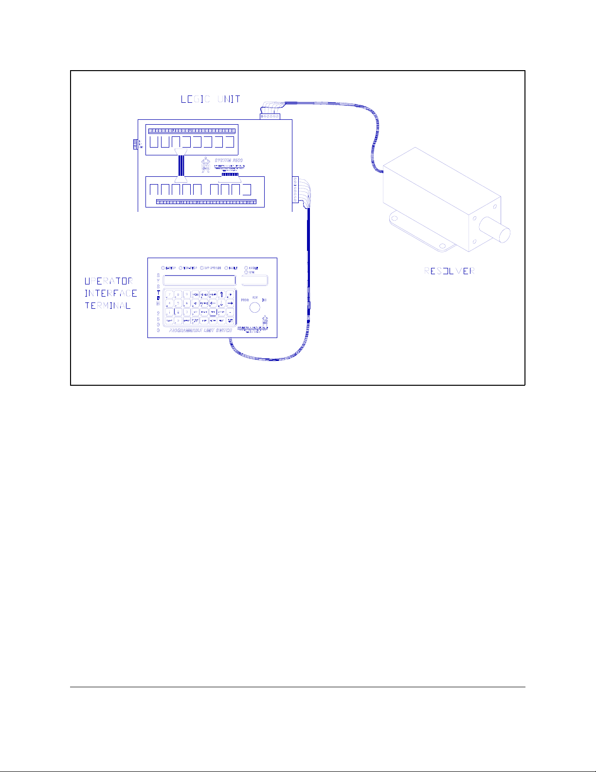
Figure 1
System 2500 Components
1.3 Specifications
Input Ratings
Primary Input Power Requirements: 115VAC ± 15VAC, 60Hz, 1 Ampere
Run Signal Input (Terminals 34 & 35): 115VAC @ 10mA nominal
or 24VDC @ 2mA nominal
Die Protection Inputs and Auto SS Input: Inputs are active low (ground); to activate,
external circuit must sink 0.6mA (typical),
1.2mA (maximum)
Output Ratings
28VAC Output: 450mA maximum
+12VDC Output (for sensors): 100mA maximum
System 2500 Operating & Installation Manual - Revision 07 1-3
Page 8

Switching Output Ratings
Electromechanical Relay Outputs: 5.0 Amperes @ 120VAC or 24VDC
AC Solid State Relay Outputs: 1.5 Amperes @ 240VAC
DC Solid State Relay Outputs: 3.0 Amperes @ 60VDC
General
Response Time, Die Protection
(static type, time from input change to E-Stop
relay contacts open): 25mS (typical), 33mS (maximum)
Response Time, Die Protection
(cycling type, time from window position
passed to E-Stop relay contacts open): 20mS (typical), 28mS (maximum)
Pulse width recognized by N.O. die protection
input (low pulse): 1mS minimum
Pulse width recognized by N.C. die protection
input (high pulse): 9mS minimum
Maximum Operating Speed: 2000 SPM
Maximum Ambient Temperature: 45°C (113F°)
System 2500 Operating & Installation Manual - Revision 071-4
Page 9

Section 2 OPERATION
2.1 Using the Operator Interface Terminal
The OIT is the means by which the operator can control the operation of the System 2500. The
following features should be noted on the terminal:
C A large LCD (liquid crystal display) for messages
C Keyboard consisting of 32 keys
C A four digit LED display (red characters in the upper right hand corner)
C Mode Selector Keyswitch (lower right corner)
C Six individual status indicators: E-STOP, TOP-STOP, D/P BYPASS, FAULT,
ANGLE, and RPM
The operator should familiarize himself with these features since they will be referred to
frequently in the instructions following.
2.1.1 Keyboard Use
The leftmost portion of the keyboard is a set of numerical keys for entering data when
programming. The remaining keys are function keys which cause some action to occur when
pressed in the proper sequence. Some of the function keys are for general use and their functions
are always active. These are listed in the description following. The keyboard is illustrated on
the foldout in the back of this manual. This foldout should be referred to during the description
of keyboard use.
2.1.1.1 ANGLE/RPM Key
The four digit red display is intended to continuously display crankshaft angle or speed. The
angle is being displayed if the ANGLE light above the four digit red display is lit. The speed in
revolutions per minute (rpm) is being displayed if the RPM light above the four digit red display
is lit. The operator may alternate between angle and rpm by pressing the ANGLE/RPM key.
NOTE: The four digit display is also used to display error codes. When an error code is
being displayed, the angle and speed cannot be viewed. The error must first be cleared
with the CLEAR key.
System 2500 Operating & Installation Manual - Revision 07 2-1
Page 10

2.1.1.2 HELP Key
The operator may request a Help screen from the System 2500 PLS by pressing the HELP key.
The Help screens are intended to aid the operator by giving additional information and
explanation of the current stage of the program sequence. Some Help screens may be more than
two lines long. If the last character on the screen is a down arrow, more help information is
available. The operator may press the down arrow key to view the additional lines. The operator
may terminate a help screen and return to the program at any time by pressing the EXIT key. If
no help screen is available for the present program sequence, a message will inform the operator
that a help screen is not available.
2.1.1.3 CLEAR Key
The CLEAR key is used for two main functions. The first function is to remove any data input in
progress. If the operator keys in the wrong data but has not yet pressed the ENTER key, he may
press the CLEAR key to remove the entire data input. The correct data may then be keyed in.
The CLEAR key cannot remove any data once it has been en tered with the ENTER key.
The second function of the CLEAR key is to remove stops and faults. If a counter reaches its
programmed limit and stops the machine, the CLEAR key may be pressed to reset the counter
and allow the machine to be restarted. If a system fault occurs (such as a die protection fault),
once the cause of the fault has been corrected the error condition can be removed by pressing the
CLEAR key.
2.1.1.4 BRIGHT and DIM Keys
The intensity of the 80 character liquid crystal display can be varied by using the BRIGHT or
DIM keys. Pressing the BRIGHT key will increase the intensity of the display. If additional
brightness is required, the bright key must be released and pressed again. The DIM key is used to
decrease the brightn ess of the display.
2.1.1.5 MAIN MENU Key
If at any time during the programming procedure the MAIN MENU key is pressed (lower right
corner of keyboard) the Main Menu will be immediately displayed. This menu is the starting
point for all programming of the unit. (See Section 2.2 for more information on the menu
approach of the System 2500). NOTE: The MAIN MENU key will not cause the Main Menu to
display if there is a communication failure between the OIT and Logic Unit.
2.1.2 Mode Selector Keyswitch
System 2500 Operating & Installation Manual - Revision 072-2
Page 11

The Mode Selector is a three position keyswitch. The key may only be removed in the RUN
position. The operating conditions for the three positions are as follows:
C RUN - This is the normal operating mode of the System 2500. When the key is in
this position, the operator can only view limit switch setpoints or the die
protection input modes. He cannot add, erase, or edit PLS setpoints in this
position, nor can he edit the die protection setup. There is no E-Stop issued by the
System 2500 in this mode unless an error condition is present.
C PROG - This is the program mode of the System 2500. When the key is in this
position limit switch setpoints can be added, erased, or edited; Die-Protection can
be edited; and setups can be stored to memory or recalled from memory. An
E-Stop is always
motion while programming.
issued by the System 2500 in this mode to prevent machine
C INC - This is the increment mode of the System 2500. When the key is in this
position, PLS setpoints can be increased or decreased by one degree at a time. An
E-Stop is not issued by the System 2500. The increment mode allows the operator
to fine tune PLS setpoints while the machine is in operation.
2.2 Menu Selection Using the LCD
The LCD (liquid crystal display, in the center of the OIT) provides the operator with information
needed to program the unit. This is done by displaying a menu (list of choices) and allowing the
operator to select one of the menu items. On each menu one of the choices listed will be
blinking. The blinking effect is called the cursor
operator has selected. The cursor can be moved to a different choice on the menu using the
arrow keys (see the figure on the foldout in the back of the manual). Once the cursor is on the
item desired, the operator can press the ENTER key to get further information about that item.
The operator is not required to memorize any function names or keyboard entry sequences.
2.2.1 Main Menu
The main menu is the first list of options offered to the operator during programming of the
System 2500. There are five major functions from which to choose:
and is used to identify which item on the list the
C PLS - (Programmable Limit Switch) This is the function of the unit wherein the
output relays can be programmed to switch on or off at specified points of the
machine cycle.
C COUNTERS - There are three user presettable counters in the System 2500 which
System 2500 Operating & Installation Manual - Revision 07 2-3
Page 12

can be accessed by selecting this function. The total stroke count of the machine
as seen by the unit can also be displayed here.
C STORE/RECALL - With the System 2500 a particular setup (which includes both
limit switch and die protection settings) can be stored under a name or number
and recalled at a later time. This saves the operator from having to re-enter
different settings each time a die is changed.
C DIE-PROT - (Die Protection) In this function, inputs to the System 2500 which
are wired to appropriate die sensors can be programmed to detect fault conditions
related to the die and stop the machine before damage occurs.
C STOPS/FAULTS - This function allows the operator to view explanations of Top
Stop and Emergency Stop conditions when these conditions occur.
To select any of the above functions the operator must move the cursor to the desired function
using the arrow keys, then press the ENTER key.
2.3 Programmable Limit Switch (PLS) Functions
The Programmable Limit Switch functions are accessed by pressing the ENTER key while the
cursor is on PLS in the Main Menu. After pressing the ENTER key, the LCD will display the
PLS Menu. This menu has two options from which to choose:
C OUTPUTS - This choice will allow the operator to program the relay outputs of
the System 2500. Pressing the ENTER key with the cursor on OUTPUTS will
cause the Outputs Menu to be displayed. The options available from the Outputs
Menu are described in Section 2.4.
C CONFIGURE - This selection allows the operator to program certain information
that enables the System 2500 to operate properly with the machine on which it is
installed. This includes detecting motion of the machine crankshaft, setting the
resolver zero point when the crankshaft is at zero position, etc. Further
instructions for programming the configuration data are described in Section 2.5.
To select either of the above functions the operator must move the cursor to the desired function
using the arrow keys, then press the ENTER key.
2.4 OUTPUTS
The Outputs Menu gives the operator three choices for programming or monitoring the status of
System 2500 Operating & Installation Manual - Revision 072-4
Page 13

the output relays on the System 2500. These choices are as follows:
C SETPOINTS - This option allows the operator to program the output relays to turn
on or off at different points in the machine stroke (referred to as the 'setpoints' of
an output channel). This function is described in Section 2.4.1.
C VIEW STATUS - Choosing this option will produce a display which indicates the
on/off status of the output relays, in groups of 8. This function is described in
Section 2.4.2.
C COUNTED OUTPUTS - This menu option gives the operator an opportunity to
program any of outputs 1 through 8 so that they are tied to a counter. This means
that these outputs can be programmed to be active only on every other stroke, or
every third stroke, or every fourth stroke, etc. This is useful for operations which
should take place on a periodic basis but not on every stroke. The procedure for
setting up outputs in this way is described in Section 2.4.3.
To select any of the above functions the operator must move the cursor to the desired function
using the arrow keys, then press the ENTER key.
2.4.1 SETPOINTS
Selection of the SETPOINTS item from the Outputs Menu will allow the operator to view and
modify the setpoints of the individual limit switch channels. These setpoints are the crankshaft
angles at which the corresponding output relay will turn on or off. If the mode selector keyswitch
is in the RUN position, the setpoints can only be viewed. If the keyswitch is in the PROG
(Program) position, setpoints can be added, erased, or edited. If the keyswitch is in the INC
(Increment) position, individual setpoints can be incremented or decremented in one degree
increments.
The operator must enter the number of the channel he wishes to view by keying in a valid
channel number and pressing the ENTER key. Valid channel numbers are 1 thru 16. Once a
particular channel is displayed, the operator may view other channels by using the up and down
arrow keys.
If the channel contains more than two setpoint pairs, the operator can use the left and right arrow
keys to view the other setpoint pairs. When a channel contains no setpoints, a message stating
that no setpoints are programmed will be displayed and the channel output will always be off.
2.4.1.1 Adding Setpoints
To add a setpoint pair the operator must select the desired channel and press the ADD key.
System 2500 Operating & Installation Manual - Revision 07 2-5
Page 14

Setpoints can only be added when the mode keyswitch is in the PROG (Program) position. The
on and off points must then be entered as instructed. If incorrect data is keyed in, the CLEAR
key will remove the entire line and the correct data can then be entered. The CLEAR key cannot
be used once the ENTER key has been pressed to store the data. Once this has been done the
setpoints must be erased or edited.
If a channel is restricted no setpoints can be added. An 'R' will appear in the display beside the
channel number when this is the case. See Section 2.5.5 for more information on restricting
channels.
If necessary, more than one setpoint pair can be added on any channel to turn the output on and
off more than once in a machine stroke. When doing so, the setpoint pairs must be programmed
so that they switch on and off in alternating sequence; that is, the angles entered cannot be in
such an order so that two on points occur in succession followed by two off points. A warning
message will occur if programmi ng is attempted in this way.
Additionally, certain situations prevent the operator from programming more than one on/off pair
on a channel. Only one setpoint pair is allowed on an output which is to be speed advanced (see
Section 2.4.1.5). Attempting to add a second setpoint pair to a channel having advanced
setpoints will produce an error message. Also, if an output channel is being used as the special
assigned stop output for a Cyclic Die-Protection fault (see Section 2.9.2), or if the channel is tied
to the counter (Section 2.4.3), then only one setpoint pair can be programmed. A message will
be displayed signifying either of these last two conditions.
If the unit is programmed for Automatic Single Stroke operation, on/off setpoints cannot be
programmed on channels 7 or 8. During Auto Single Stroke the unit takes control of these
outputs and turns them on and off as required for proper operation (see Section 2.8.4).
WARNING: PLS OUTPUTS OF THE SYSTEM 2500 ARE NOT TO BE USED AS THE
PRIMARY INPUTS TO A PRESS CONTROL.
2.4.1.2 Erasing Setpoints
With the keyswitch in the PROG mode, setpoint pairs can be erased with the ERASE key. The
operator must select either the on or off setpoint of the pair to be erased. To select the setpoint
the operator must use the right or left arrow keys. When either the on or off setpoint of the pair
to be removed is blinking, the ERASE key must be pressed. A message will be displayed asking
the operator to confirm the pair to be erased. If the correct pair has been selected the operator
must again press the ERASE key. If the incorrect pair has been selected, the operator may press
any key other than the ERASE key to abort the erase operation.
If a channel is restricted no setpoints can be erased. An 'R' will appear in the display beside the
channel number when this is the case. See Section 2.5.5 for more information on restricting
System 2500 Operating & Installation Manual - Revision 072-6
Page 15

channels.
2.4.1.3 Editing Setpoints
To edit an on or off setpoint, the operator must first place the mode selector keyswitch in the
PROG mode. Then the setpoint to be modified must be selected with the right or left arrow keys.
When the setpoint to be modifi ed is b linking, the operator may key in the new setpoint value. If
a mistake is made in keying in the data, the CLEAR key may be pressed to clear the data. Also,
to discontinue editing without making any changes, the EXIT key can be pressed which will
redisplay the original setpoint value. Once the new setpoint is keyed in as desired the ENTER
key must be pressed. The operator is then asked to confirm the change by pressing the YES key.
If the operator does not want to confirm the change, he may press any key other than the YES key
and the entire data entry sequence will be canceled.
If the operator desires to modify a setpoint that is not speed advanced so that it will be speed
advanced, he must move the cursor to that setpoint and press the ADVAN key. Only one
setpoint pair can be programmed on a channel if one of the setpoints is to be advanced (see
Section 2.4.1.5 for information on Speed Advanced Outputs). A message will then be displayed
asking the operator to confirm that the setpoint should be changed to a speed advanced setpoint.
The YES key should be pressed to proceed with the change, or any other key to cancel the
change.
If a channel is restricted its setpoints cannot be edited. An 'R' will appear in the display beside
the channel number when this is the case. See Section 2.5.5 for more information on restricting
channels.
2.4.1.4 Timed Outputs
Channels 1 thru 8 can be programmed as timed outputs. A timed output will come on at the
angle of the on setpoint, and will turn off after the programmed dwell time. To add a timed
output, the operator must follow the steps of section 2.4.1.1, except the TIME key must be
pressed before entering the off setpoint. The dwell time must then be entered. Allowable dwell
times are from 2 to 2046 milliseconds (a millisecond is 1/1000 of a second). The System 2500
PLS will only store even number dwell times. If an odd dwell time is entered, it will be rounded
up to the next even number. A maximum of 5 timed outputs is allowed.
2.4.1.5 Speed Advanced Outputs
On PLS channels 1 thru 8, either the on or off setpoint or both setpoints of a setpoint pair can be
speed advanced. If a setpoint is advanced, its value is decreased as the machine speed is
increased. This means that the setpoint will occur earlier in the cycle to compensate for the
increased speed. To speed advance an output the operator must first determine the setpoints
System 2500 Operating & Installation Manual - Revision 07 2-7
Page 16

necessary for proper actuation of the output at maximum speed and at minimum speed (see
Section 2.5.7 for a description of this procedure). The setpoint value should be left programmed
at the correct setting for minimum
status, by pressing the ADVAN key while the cursor is on the setpoint. The screen will then ask
the operator to confirm that the setpoint is to be advanced. Pressing the YES key at this point
will program that setpoint as advanced and the 'A' label will appear beside the setpoint as an
indicator.
Configuration of the PLS Output Speed Advance is necessary for speed advanced outputs to
function properly (see Section 2.5.7). The System 2500 PLS will calculate a speed advance
constant from data entered for PLS Output Speed Advance in the configuration menu. The speed
advance constant will then be used to adjust the setpoint angle of advanced setpoints as machine
speed changes.
Note that once the data in the configuration menu is programmed, it should not be reprogrammed
if the operator later chooses to advance another setpoint. All future setpoints programmed as
advanced will use the speed advance constant already programmed. For later setpoints
programmed as advanced it will not be necessary to test at maximum speed. For these setpoints
it will only be necessary to enter the angle for proper operation at minimum speed and then edit
the setpoint to advanced.
speed. The setpoint should then be edited to 'Advanced'
If a channel is to be programmed with advanced setpoints and the correct setpoints are already
known, the setpoints can be directly programmed as advanced (rather than editing them to
advanced status after they have been programmed). To program a setpoint angle to be speed
advanced, the steps of section 2.4.1.1 must be followed to program the channel, except that the
ADVAN key must be pressed after the angle is keyed in and before the ENTER key is pressed.
Only one setpoint pair can be programmed on an output channel using Speed Advance.
2.4.1.6 Incrementing Setpoints
Individual on or off setpoints can be fine tuned by using the Increment mode. To use this mode
the keyswitch must be in the INC position. When in the increment mode, the System 2500 does
not generate an E-Stop. Since no E-Stop is generated, this mode allows adjustment of a setpoint
while the machine is running. To adjust a setpoint the operator must first select the channel and
then move the cursor to the on or off setpoint to be adjusted. When the desired setpoint is
blinking, the operator must press the up or down arrow keys to increase or decrease the setpoint
value, respectively. In many cases, the arrow key will have to be pressed more than once to
change the setpoint by one degree (the setpoint changes by only a fraction of a degree each time
the key is pressed).
2.4.2 VIEW STATUS
System 2500 Operating & Installation Manual - Revision 072-8
Page 17

If the VIEW STATUS item is selected from the Outputs Menu, the OUTPUT STATUS screen
will be displayed. This screen indicates for each of the first eight outputs whether the output is
on or off. This information can be useful when first setting up the unit on the machine or when
troubleshooting. On the far right of the display is the down arrow symbol, which indicates that
by pressing the DOWN arrow key the status for outputs 9 through 16 will be displayed.
Remember that outputs 9 through 16 can be programmed and the change in their on/off status
observed on this screen at any time, but for any external action to occur there must be a second
relay output board installed for relays 9 through 16.
2.4.3 COUNTED OUTPUTS
By pressing the ENTER key while the cursor is on COUNTED OUTPUTS in the Outputs Menu,
the operator can access a special function for PLS outputs 1 through 8 which allows them to be
tied to a counter. This is a separate counter for this function only and is not related to the Part,
Batch, Quality Check, or Stroke counters of the System 2500 (see Section 2.6). The purpose of
the Counted Outputs function is to allow a PLS output to be programmed in the fol lowing way:
1. The output is held off for a certain number of strokes regardless of its
programmed setpoints.
2. The output becomes active for one stroke so that its on/off setpoints cause the
output relay to switch.
3. The cycle of steps 1 and 2 is repeated.
The effect is that the output becomes active for one stroke every five strokes, or every eight
strokes, etc. depending on the count that the operator programs. This is useful for programming
some special action such as a scrap chopper which only becomes active after several machine
strokes have been made.
The first screen displayed for this function is the Counted Outputs Menu. It offers the following
choices:
C VIEW SETUP - Allows the operator to see which channels are tied to the counter
and the present stroke count.
C EDIT SETUP - Allows the operator to tie a PLS channel to the counter or remove
a channel from being tied to the counter. Also allows change of the present
counter value and which stroke count will activate the outputs.
To select either of the above functions the operator must move the cursor to the desired function
using the arrow keys, then press the ENTER key.
System 2500 Operating & Installation Manual - Revision 07 2-9
Page 18

2.4.3.1 Counted Outputs, VIEW SETUP
When VIEW SETUP is selected from the Counted Outputs Menu, the operator will see a list of
the outputs which are tied to the counter. Also shown is the stroke count on which these outputs
will be active and the current stroke count of the machine. (Remember that this is a special
cycling counter and is NOT the same as the Part, Batch, Quality Check, or Total Stroke counters
of the System 2500. See Section 2.6 for information regarding these counters). This information
is important since outputs tied to the counter will NOT be active on every stroke. The operator
or maintenance personnel may need to know why a certain PLS output is not on during its
programmed on portion of the stroke. By viewing this screen the operator will know when the
counter-tied outputs will be active.
2.4.3.2 Counted Outputs, EDIT SETUP
In order to program the necessary information to use the Counted Outputs function, the operator
must select EDIT SETUP from the Counted Outputs Menu. Prior to doing this, the keyswitch
must be placed in the PROG position. If EDIT SETUP is selected with the keyswitch in another
position an error message will appear. After EDIT SETUP is selected, the operator will be asked
to enter a special access code to proceed. This is the same code that is required to enter the
Configure Menu (see Section 2.5). The code is printed on the back page of this manual. It is
suggested that this code be given to qualified users only. If the keyswitch is turned to a position
other than PROG while the Counted Outputs setup is being edited, the error message will appear
and the operator will have to re-enter the access code. Through the keyswitch and access code
protection any undesired changes to this special function of the PLS outputs are prevented.
Once the access code has been properly entered the display will contain all the information
required for the Counted Outputs function. The following will be displayed:
C CHANNELS - A list of the PLS output channels which are presently tied to the
counter.
C COUNT - The present stroke count of the machine (as pertains to this function).
When this count is the same as the ACTIVE COUNT, the PLS outputs listed
beside CHANNELS will be active for one stroke.
C ACTIVE COUNT - The stroke count at which the PLS outputs tied to the counter
will become active. On this stroke count the PLS outputs listed beside
CHANNELS will follow the on/off setpoints that have been programmed for each
output. Until the count is reached, these outputs will always be off.
C COUNT ANGLE - The crankshaft angle at which the counter will count up, i.e.
the place in the stroke where the COUNT value on this screen will change.
System 2500 Operating & Installation Manual - Revision 072-10
Page 19

2.4.3.3 CHANNELS
If the operator wishes to tie a PLS output to the special counter, the ADD key must be pressed.
After this key is pressed, the display will prompt for entry of the channel to be added. PLS
channels 1 through 8 may be tied to the counter. Key in the desired channel number and press
ENTER. The display will then return to the Counted Outputs setup information screen with the
new PLS channel number added to the list.
Any channel to be tied to the counter can have only one setpoint pair programmed (one 'on'
setpoint and one 'off' setpoint). Additionally, the channel cannot be one that is already used as
the assigned output for a Die-Prot Cyclic fault. If the unit is set up for Auto Single Stroke
operation, outputs 7 and 8 cannot be tied to the counter. Attempting to add any channel
previously programmed as described here will cause an error message to appear.
To remove a PLS output from being tied to the counter, the operator must first press the
REMOVE key. The LCD will then request the number of the channel to be removed. Key in the
channel number and press ENTER. The display will then return to the Counted Outputs setup
information screen with this channel number deleted from the list. Remember that removing an
output from being tied to the counter means that the output will no longer be held off until the
active stroke, but will now be active on every stroke. If this is not desirable the operator may
turn the output off by erasing its setpoints (see Section 2.4.1.2).
Any channel that has been restricted previously cannot be tied to the counter nor removed from
being tied to the counter. Any unrestricted channel that has been tied to the counter can then be
restricted to prevent any further changes.
2.4.3.4 COUNT
When setting up outputs that are tied to the counter, the operator may find it necessary to adjust
the count that the machine is presently on to make the outputs become active on the proper
stroke. To do so the operator must use the arrow keys to move the cursor to the current count
value (upper right corner), then key in new value and press ENTER. For example, suppose the
press has a repeating five stroke sequence where certain PLS outputs are to become active on the
fifth stroke. If during setup of this function the press is mechanically two strokes away from the
stroke where the PLS outputs are to be active, then the operator should enter the number 3 for the
present COUNT.
2.4.3.5 ACTIVE COUNT
The ACTIVE COUNT is, as the name implies, the stroke count on which the PLS outputs tied to
the counter are to become active for one stroke. The ACTIVE COUNT is the maximum value
that the counter will reach; in other words, as the press strokes the COUNT will increase until the
ACTIVE COUNT value is reached and on the next stroke the COUNT will start over at 1. To
System 2500 Operating & Installation Manual - Revision 07 2-11
Page 20
change the ACTIVE COUNT, use the arrow keys to move the cursor to the ACTIVE COUNT
value then key in a new value and press ENTER. For example, if the outputs tied to the counter
should only be active every five strokes (make four strokes with these outputs OFF then one
stroke where the outputs switch normally), enter the number 5 for ACTIVE COUNT. If the
outputs should be active every eight strokes, enter the number 8 for ACTIVE COUNT. The
maximum ACTIVE COUNT value that can be entered is 255.
Remember also that the correct stroke in the cycle that the machine is presently on should be
entered beside COUNT on this screen (see Section 2.4.3.4). This must be done to insure that the
sequencing is correct.
2.4.3.6 COUNT ANGLE
The count angle is the crankshaft angle where the counter will change. To change the count
angle move the cursor to COUNT ANGLE using the arrow keys then key in a new angle (0 to
359 degrees) and press ENTER. In most cases this angle can be set at zero degrees (top of
stroke). However, if the die setup is such that a PLS output must be ON through zero degrees
during the active stroke, the count angle can be set to another value. The reason for this is that it
is not desirable to have the count angle change while the PLS outputs are programmed to be ON.
If this occurs, as soon as the count changes to the active count all PLS outputs tied to the counter
will immediately turn on. Likewise, when the count changes from the active count back to 1, all
PLS outputs tied to the counter will immediately turn off. It is more desirable to have the counter
change at a point in the stroke where all PLS outputs tied to the counter are programmed to be off
so that the change in count will not immediately affect those outputs.
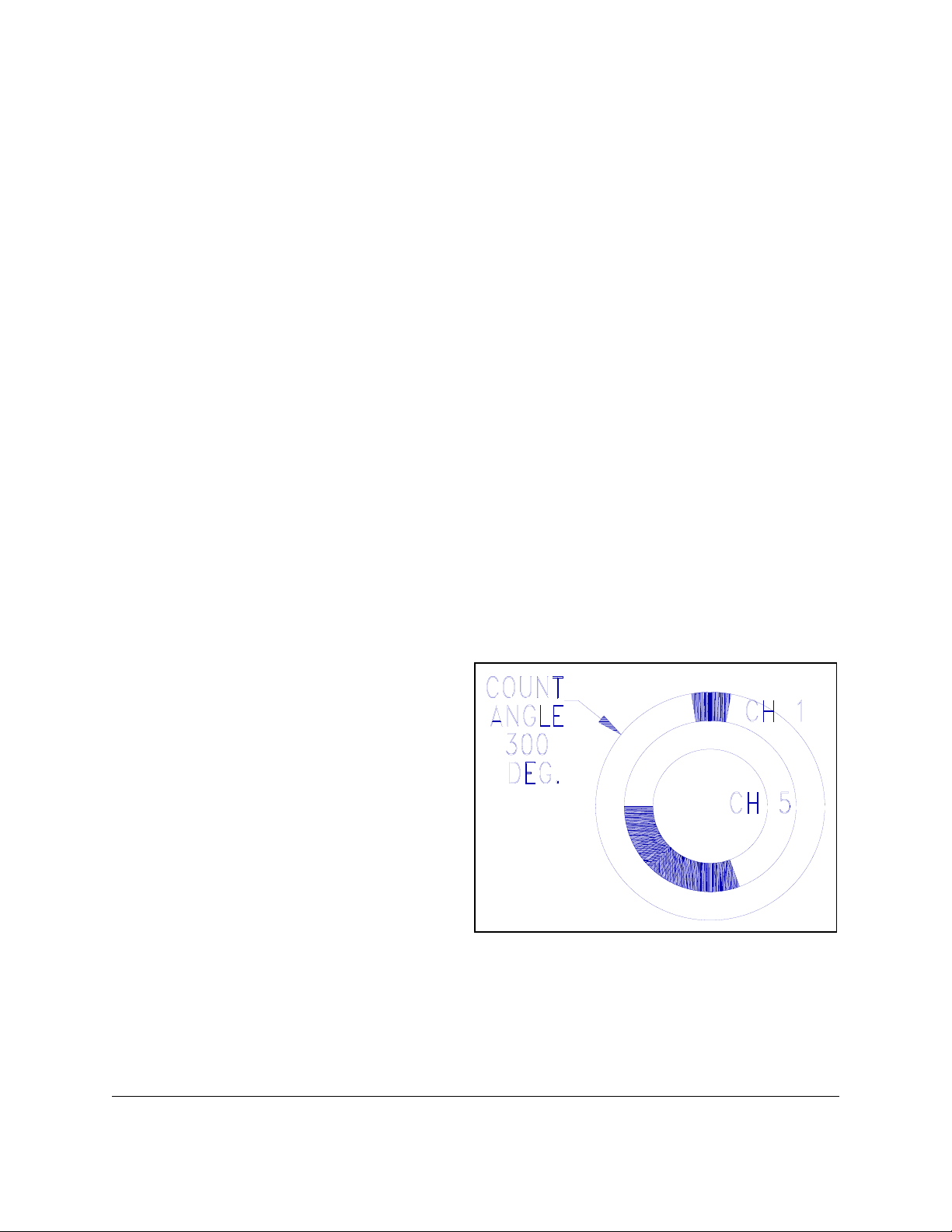
Example: (See Figure 2) PLS output
channels 1 and 5 are tied to the counter.
During the active stroke, channel 1 is to turn
on at 350 degrees and turn off at 10 degrees.
Channel 5 is to turn on at 160 degrees and
turn off at 270 degrees. In this case it would
be better to change the COUNT ANGLE
from 0 degrees to 300 degrees, since at this
point in the stroke channels 1 and 5 are both
off. In this way, the count will change to the
active count at 300 degrees; both output
channels can turn on and off properly at their
programmed setpoints; then when 300
degrees is reached again the counter will
recycle to 1 and the outputs will become
inactive.
System 2500 Operating & Installation Manual - Revision 072-12
Figure 2
Desired Location of Count Angle
Page 21

2.5 CONFIGURE
The Configure routines will allow the operator to program into the System 2500 important
information relating to the machine on which it is installed. The configuration routines can only
be entered with the mode selector keyswitch in the PROG position. Switching the keyswitch
from the PROG position will terminate the configuration routine (except for the special case of
setting TOPSTOP angle - see Section 2.5.3). To access these routines the operator must select
CONFIGURE from the PLS Menu.
2.5.1 Configure Access Code Screen and Menu
Selection of CONFIGURE will display a screen which will ask the operator to enter the
configuration access code. Failure to enter this code correctly will prohibit the operator from
entering the Configure Menu. The access code is printed on the last page of this manual. It is
suggested that the code be given to qualified users only. The Configure Menu allows the
operator to make modifications to the System 2500 PLS setup which can alter the operation of
the unit. Once the Configure Menu has been attained one of the following functions may be
selected:
C MOTION DETECTOR - Provides for entry of data for the internal motion
detector function which verifies that resolver is connected and operat ing p roperly.
C TOPSTOP - Allows entry of the crankshaft angle where a stop signal to the
machine should occur in order for the machine to come to a stop at the top of the
stroke.
C TOPSTOP ADVANCE - Allows entry of the information needed by the System
2500 to advance the TOPSTOP setpoint angle as the crankshaft speed increases.
C RESTRICTED CHANNELS - Allows the operator to add or remove restricted
channels.
C OFFSET - Selection of resolver zero point.
C PLS OUTPUT ADVANCE - Allows entry of the information needed by the
System 2500 to advance PLS setpoints as the crankshaft speed increases.
To select any of the above functions the operator must move the cursor to the desired function
using the arrow keys, then press the ENTER key.
2.5.2 MOTION DETECTOR
System 2500 Operating & Installation Manual - Revision 07 2-13
Page 22

The motion detector is used as a check by the System 2500 PLS to insure that the resolver is
properly wired, the input circuits are functioning, and the resolver is coupled to the machine
crankshaft. The operator must enter three values into the motion detector configuration. These
values are:
C THRESHOLD - This is the crankshaft speed at which the System 2500 will
recognize that the machine is in motion. The speed entered here should be 75% of
the machine's slowest operating speed.
C CLUTCH TIME - This is the time required after the machine control gives the run
signal before crankshaft motion begins (i.e., clutch engagement time). The range
of values that can be entered is 2 to 998 milliseconds. This time should be set to
as small a value as possible.
C MAX SPM - This the maximum machine speed in strokes per minute (SPM).
All data requested by the motion configuration must be entered for the unit to operate properly.
To enter or change any value move the cursor to the desired value, key in the new data and press
ENTER. The System 2500 will accept only even numbers for this data; entry of odd values will
be rounded up to the next even value. Note that if the value entered for MAX SPM is less than
the value entered for THRESHOLD, an error will be generated. To clear the error correct values
must first be entered and then the CLEAR key pressed. Additionally, an error will be generated
if the value entered for MAX SPM is less than the value entered for MINIMUM PRESS SPEED
in the Speed Advance data screen. In this case either the MAX SPM or MINIMUM PRESS
SPEED must be correc ted to i ts p rop er va lue before pressing t he C LEAR key.
The Motion Detector data is used in the following way: When the machine 'RUN' signal
becomes active (terminals 34 and 35) the System 2500 is alerted that the machine has been
commanded to stroke. The unit then expects machine motion (i.e., resolver motion) to occur
within the time limit programmed in CLUTCH TIME. Machine motion is recognized when the
machine crankshaft is turning faster than the speed programmed as THRESHOLD. If the System
2500 PLS does not detect motion at a speed greater than THRESHOLD within the time limit
programmed as CLUTCH TIME, it assumes that a fault has occurred and de-energizes the EStop relay. The MAX SPM data entered is used in other resolver related checks and also in
calculating Speed Advance constants (see Sections 2.5.4 and 2.5.7).
2.5.3 TOPSTOP
Certain functions of the System 2500 can be programmed so that stop conditions will allow the
machine to stop at the top of its stroke rather than cause an immediate stop. The System 2500
accomplishes this by opening the E-Stop relay at the proper angle in the stroke so that the
System 2500 Operating & Installation Manual - Revision 072-14
Page 23

machine will come to a stop at the top. This is called the 'stopping angle' in further text of this
manual. The Topstop selection from the Configure Menu (labeled TOPSTP) allows the operator
to program this angle so that an accurate top stop will occur.
The Topstop configuration display indicates on the top line the angle at which the E-Stop relay
will open when a top stop signal is generated. The bottom line allows the operator to enter a new
angle if required. This configuration step is unique in that the operator may move the keyswitch
to the RUN position so that the top stop accuracy can be tested. When the keyswitch is moved to
the RUN position, E-STOP can be cleared (if no errors exist) and the System 2500 will allow the
machine to run. In addition, the YES key on the OIT will become active as a way to initiate the
top stop. The operator can then make several strokes, press the YES key to cause a top stop, and
note where the machine stops. If the machine does not stop on top, the operator should return the
keyswitch to the PROG position whereupon the display will allow entry of a new stopping angle
(in RUN mode no configuration data can be entered). If the machine went over top, the operator
should enter a smaller angle value (earlier in stroke). If the machine stopped short of top, the
operator should enter a larger angle (later in stroke). After entering a new angle the keyswitch
can be returned to the RUN position to test the stopping point again. (Note that after switching
back to RUN mode it will be necessary to clear the E-Stop condition by pressing the CLEAR
key). By switching between Run and Program modes and entering data, the stopping angle can
be fine tuned to stop the machine on top.
On variable speed machines it will often be desirable to use the speed advance capability of the
System 2500 to automatically adjust the stopping angle as the speed changes. In order for the
Topstop Speed Advance function to work properly its configuration data must be programmed
(see Section 2.5.4). The top stop fine tuning procedure just described can be used to find the
stopping angle of the machine at various speeds so this information can be entered into the
Topstop Speed Advance configuration. Once the Topstop Speed Advance data has been
recorded, the stopping angle itself can then be programmed as 'Advanced' so that the stop signal
will automatically occur earlier in the stroke as the speed increases. If the stopping angle is to be
programmed as advanced, the angle should be left at the setting that was found while the
machine was set for its LOWEST operating speed. This angle should be keyed in on the Topstop
display as before except that the ADVAN key should be pressed before pressing the ENTER key.
The letter 'A' will appear beside the stopping angle to designate that the angle will be advanced.
The ADVAN key should NOT be pressed while different angles are being entered during the fine
tuning process (in other words, the 'A' should not be displayed during the fine tuning process).
If it is desired to return to the Configure Menu for additional programming, be sure that the
keyswitch is in the PROG position before pressing the EXIT key. If the keyswitch is in any
position other than PROG at any step of the Configure routines other than Topstop an error
message will appear. The operator will then have to move the selector switch back to PROG and
re-enter the access code to resume the configuration functions.
System 2500 Operating & Installation Manual - Revision 07 2-15
Page 24

2.5.4 TOPSTOP SPEED ADVANCE
For variable speed machines the operator may program the stopping angle to advance (occur
earlier in the stroke) as the speed increases. For functions which result in a top stop this will
insure that the machine will continue to stop on top as the machine speed increases. In order for
a speed advanced stopping angle to operate properly, the Topstop Speed Advance configuration
data must be programmed (found under the TOPSTP ADVAN selection of the Configuration
Menu). The data values required are the minimum press speed and the stopping angle of the
machine at four different machine speeds. (The stopping angle is the crankshaft angle where a
stop signal must be given in order for the machine to stop at the top of the stroke). This
information must be determined beforehand by the operator using the procedure to be described,
and then entered in the TOPSTP ADVAN selection of the Configure Menu. If the stopping angle
is not to be speed advanced, the operator may skip programming of the Topstop Speed Advance
data.
The stopping angles for the machine can be found using the Topstop function of the Configure
Menu (see Section 2.5.3 for instructions on using Topstop). The System 2500 performs the top
stop function by opening the E-Stop relay at the proper point in the stroke to top stop the press.
By adjusting the angle entered in the TOPSTOP data screen, the machine can be made to stop on
top at the particular press speed chosen. For determining the speed advance constants, the
machine must be run at four different speeds and the correct angle for initiating a top stop must
be found for each speed and then recorded. The four speeds are:
1. Minimum machine speed.
2. Minimum speed plus one-third of the difference between maximum speed and
minimum speed.
3. Minimum speed plus two-thirds of the difference between maximum speed and
minimum speed.
4. Maximum machine speed.
Once the correct angles for initiating a stop at these four speeds have been recorded, the operator
can return to the TOPSTP ADVAN selection of the Configuration Menu to enter the angles.
Choosing TOPSTP ADVAN from the Configure Menu gives the operator access to several data
screens on which the minimum press speed and stopping angles can be entered. The operator can
use the cursor to select a data value, then key in the proper value and press ENTER. When a
'down arrow' symbol is displayed as the last character on the bottom line of the display, this
indicates that another data line is available to the operator by pressing the down arrow key while
the cursor is on the bottom line. In the same way, an 'up arrow' symbol displayed as the last
character on the top line indicates that another data line is available by pressing the up arrow key
System 2500 Operating & Installation Manual - Revision 072-16
Page 25

while the cursor is on the top line. Using the arrow keys the operator can 'scroll' through all the
lines of data that must be entered. (The only exception to data entry is the MAX SPEED shown
on the first screen. MAX SPEED is for display only and cannot be entered on the Topstop Speed
Advance screen. To change the value of MAX SPEED the operator must go to the MOTION
DETECTOR data screen, Section 2.5.2).
All speed advance data must be entered for proper operation. The data must be entered correctly
or an error will be generated. This means that the minimum press speed obviously must be less
than the maximum speed, and for each increasing
decrease (must occur earlier in the stroke). After all data has been entered, programming of
Topstop Speed Advance is complete. Thereafter if the stopping angle has been programmed as
Advanced (see Section 2.5.3), the angle will be adjusted according to this data. As the speed
increases, when a top stop is required the E-Stop relay will actually open earlier in the stroke than
at the Topstop angle that is programmed. Since this function is for advancing
the angle entered for Topstop should be left programmed for proper operation at minimum
machine speed.
2.5.5 RESTRICTED CHANNELS
It may be desired to 'lock' the on/off setpoints on a PLS channel so that they cannot be changed.
In the System 2500 PLS this is called a restricted channel. Channels one thru eight can be
restricted channels. If a channel is restricted, its setpoints cannot be erased or edited nor can any
new setpoints be added. Additionally, a restricted channel cannot be changed with regard to
special functions as follows:
speed value the stop angle programmed must
the stopping angle,
1. Restricted channels cannot be tied to the counter. If a channel previously tied to
the counter is then restricted, it cannot be removed from being tied to the counter
unless the restricted status is removed (see Section 2.4.3.3).
2. Restricted channels cannot be assigned as the special fault output for the Cyclic
mode of Die Protection. If a channel previously assigned as the fault output is
then restricted, the fault output cannot be reassigned to another channel unless the
restricted status is removed from the previously assigned channel (see Section
2.9.2).
3. Channels 7 and 8 cannot be restricted if the unit is configured for Automatic
Single Stroke operation. These output channels are reserved for a special purpose
when Auto Single Stroke is used (see Section 2.8.4).
After selecting RESTRICTED CHANNELS from the Configure Menu, the LCD will display the
list of currently restricted channels. In order to restrict a PLS channel that is not on the list the
operator must press the ADD key, then the channel number desired (1-8), then the ENTER key.
System 2500 Operating & Installation Manual - Revision 07 2-17
Page 26

To remove a PLS channel from the list the operator must press the REMOVE key, then move the
cursor to the channel number desired using the arrow keys. The CLEAR key must then be
pressed to remove the restriction from the chosen channel.
2.5.6 OFFSET
The offset is a value that the System 2500 PLS will add to its resolver reading to make up for the
difference between machine zero position and resolver zero position. The offset value is limited
to + or - 10 degrees. If an offset of greater than + or - 10 degrees is necessary, mechanical
adjustments to the coupling of the resolver to the machine must be made. To adjust the offset the
operator is required to place the machine at its zero position (this position is usually top dead
center). The operator will be instructed to press the CLEAR key and then the '0' key. The
System 2500 PLS will calculate and display the necessary offset. If the offset is out of range, the
System 2500 PLS will retain the previous offset value.
2.5.7 PLS OUTPUT SPEED ADVANCE
In many applications it will be advantageous to have the on/off setpoints of a PLS channel to
advance (occur earlier in the stroke) as the speed increases. For example, an air blowoff for parts
may need to actuate earlier in the stroke as the machine speed increases. In order for setpoints
which are advanced in this way to operate properly, the PLS Output Speed Advance
configuration data must be programmed. The two data values required are the setpoint angle
which activates the desired output properly at minimum machine speed and the setpoint angle
which activates the output properly at maximum speed. This information must be determined
beforehand by the operator using the procedure to be described, and then entered in the PLS
Output Speed Advance selection of the Con figure Menu (labe led OU TPUT A DVAN). If no PLS
outputs are to be programmed as Advanced, it is not necessary to program the PLS Output Speed
Advance data.
For example, if the operator wishes to speed advance the 'On' setpoint of a PLS output, he must
first run the machine at maximum speed and adjust the 'On' setpoint of that output until the
desired action occurs at the proper point in the stroke. This adjustment can be made by stopping
the machine and editing the setpoint (see Section 2.4.1.3) or by using the Increment feature to
change the setpoint (see Section 2.4.1.6). Once the correct setpoint for maximum speed has been
found and recorded, repeat the test for minimum speed. Then leave the setpoint at the minimum
speed setting but edit the setpoint to be an Advanced setpoint (see Section 2.4.1.5). The operator
can now go to the PLS Output Speed Advance selection of the Configuration Menu to enter the
two recorded setpoint angles.
Choosing OUTPUT ADVAN from the Configure Menu gives the operator access to two data
screens on which the setpoints found for minimum and maximum press speed can be entered.
System 2500 Operating & Installation Manual - Revision 072-18
Page 27

The operator can use the cursor to select a data value, then key in the proper value and press
ENTER. When a 'down arrow' symbol is displayed as the last character on the bottom line of the
display, this indicates that another data line is available to the operator by pressing the down
arrow key while the cursor is on the bottom line. In the same way, an 'up arrow' symbol
displayed as the last character on the top line indicates that another data line is available by
pressing the up arrow key while the cursor is on the top line. Using the arrow keys the operator
can access both lines of data which must be entered. (NOTE: The MAX SPEED and MIN
SPEED shown on the top line of the first screen are for display only and cannot be entered on the
PLS Output Speed Advance screen. To change the value of MAX SPEED the operator must go
to the MOTION DETECTOR data screen, Section 2.5.2. To change the value of MIN SPEED
the operator must go to the TOPSTP ADVAN data screen, Section 2.5.4).
Both setpoint angles for Output Speed Advance must be entered for proper operation. The data
must be entered correctly or an error will be generated. This means that the angle entered for
maximum speed must be a smaller number than the angle entered for minimum speed (must
occur earlier in the stroke). After all data has been entered, programming of Output Speed
Advance is complete. Thereafter any PLS setpoint which is programmed as advanced (see
Sections 2.4.1.5) will be adjusted according to this data. For example, as the speed increases an
'on' setpoint will actually turn on earlier in the stroke than the angle that is programmed. Since
this function is for advancing
have its angle programmed for proper operation at minimum machine speed.
programmed setpoints, any setpoint to be speed advanced should
WARNING: PLS OUTPUTS OF THE SYSTEM 2500 ARE NOT TO BE USED AS THE
PRIMARY INPUTS TO A PRESS CONTROL.
2.6 COUNTERS
The System 2500 PLS has four counters: Part Counter, Batch Counter, Quality Check Counter,
and Stroke Counter. To access the counter routines the operator must select COUNTERS from
the Main Menu. From the Counter Menu the operator may select any of the four counters.
2.6.1 PART Counter
The part counter is used to count the number of parts of a run. From the part counter display the
operator can view the current part count, the part count limit and the part counter status (active or
inactive). If the part counter is inactive, the count will not change. If the part counter is active,
the count will increment in one of two ways:
1. If a Die Protection input is programmed to act as a Part Detector (either 1 Part or 2
System 2500 Operating & Installation Manual - Revision 07 2-19
Page 28

Part) and Die Protection is active (not bypassed) then the count will increment
whenever a part is seen by this input. (Remember that the part counter must still
be set active for counting to take place as noted earlier). If an input is
programmed as a Part Detector but Die Protection is bypassed, no counting will
take place.
2. If no Die Protection input is programmed as a Part Detector then the part counter
will increment at 270 degrees just as the stroke counter. In this mode the counter
acts as a presettable stroke counter which can stop the machine.
Once the counter reaches the parts count limit, the System 2500 PLS will generate a top stop for
the machine. (See Section 2.5.3 for description of the Topstop function). When the operator is
ready to restart the machine the top stop can be removed by pressing the CLEAR key. Clearing
the top stop also resets the part counter to zero.
If the keyswitch is in the PROG position, the counter operation can be programmed by the
operator. The part counter can be turned off (no counting whatsoever) by pressing the DOWN
arrow key, or turned on by pressing the UP arrow key. If the part counter is not being used, it
should be turned off. The counter can be reset to zero by pressing the '-' (dash) key. (Be careful
not to reset the counter accidentally!) Also, the Part Count Limit can be changed by keying in
the desired value and pressing the ENTER key. This limit is the count at which a top stop will be
issued to the machine. The maximum count limit is 999999.
2.6.2 BATCH Counter
The batch counter is used to count the number of strokes per batch. If a total part run is to
contain several batches (such as parts per box), the batch counter can be used to stop the process
after each batch limit has been reached.
The batch counter operates in exactly the same manner as the part counter. The counting
function is tied to the Part Detector portion of Die Protection in the same way that the part
counter is tied. All operations on the batch counter such as turning on, turning off, resetting, and
entry of the batch count limit are performed by the operator in the same way as for the part
counter. If the batch counter is not being used, it should be deactivated.
2.6.3 QUALITY Counter
The quality counter is used to count the number of strokes between quality control checks. The
quality counter operates in exactly the same manner as the part counter. The counting function is
tied to the Part Detector portion of Die Protection in the same way that the part counter is tied.
All operations on the quality counter such as turning on, turning off, resetting, and entry of the
System 2500 Operating & Installation Manual - Revision 072-20
Page 29

quality count limit are performed by the operator in the same way as for the part counter. If the
quality counter is not being used, it should be deactivated.
2.6.4 STROKE Counter
The stroke counter is used to record the total number of machine strokes since the System 2500
was connected to the machine. The stroke counter is incremented each time the machine passes
270 degrees. The stroke counter is always active. It cannot be reset by the user.
2.7 STORE/RECALL
In the System 2500, the information which includes PLS setpoints, restricted channels, and die
protection input program is called the current setup. This information determines how the
System 2500 will perform as the machine strokes. Programmed data such as PLS setpoints or die
protection input modes may have to change from job to job or as machine dies are changed.
Ordinarily, this would require having to manually change each separate PLS setpoint and
reprogram each die protection input individually. To avoid having to manually make each
separate change, the System 2500 allows the operator to store the current setup and assign it a
name so that it can be recalled in its entirety when needed later. This is done using the
Store/Recall Menu. This menu can be accessed by selecting STORE/RECALL from the Main
Menu. The mode selector keyswitch must be in the PROG position to access the store and recall
functions. If the keyswitch is in any other position an error message will be displayed.
When the Store/Recall Menu is displayed, the operator is presented with the following options:
C STORE - Allows the operator to store all the current setup information so that the
entire setup can be recalled at a later time.
C RECALL - Allows the operator to recall a setup that was stored at some previous
time.
C REMOVE - Allows the operator to remove a setup from backup memory that is
no longer needed or that has incorrect data programmed.
Any of these options can be chosen by using the arrow keys to move the cursor to the desired
option and pressing the ENTER key.
The Store/Recall Menu also displays the name of the current setup on the top line if the current
setup is one that is stored in backup memory. This means that when a setup is recalled from
System 2500 Operating & Installation Manual - Revision 07 2-21
Page 30

backup memory to be the current setup, the setup name will immediately appear on the
Store/Recall Menu. Similarly, if the current setup is stored into backup memory, the setup name
which the operator assigned will immediately appear on the Store/Recall Menu. In either case,
the name signifies that the current setup matches one stored in backup memory under that name.
If the current setup does not match one that is stored in backup memory, the message 'New data'
will be displayed. Similarly, if the current setup is edited (changed) in any way, the setup name
that appeared on the top line will be replaced with 'New data'. This signifies that the current
setup may no longer match the setup stored in backup memory since editing has been done.
2.7.1 STORE
If the operator desires to save the current setup, he may do so by selecting STORE from the
Store/Recall Menu. In order to store a setup, a name must first be given to the setup so that it can
be recalled by that name later. An illustration is shown in Figure 3. Prior to the store operation
(left side of figure) there are three setups in backup memory that have been previously stored.
Each of these setups has different PLS and Die-Prot information, and each has been given a name
(shown at the top of each page). The current setup has no name as of yet. The operator then
stores the current setup under the name 'BRACKET2'. After the store operation (right side of
figure), a copy of the current setup is in backup memory. The current setup is now called
Figure 3
Storing a Setup
'BRACKET2' to remind the operator of which setup information the System 2500 is using for
operation. This name will be displayed on the Store/Recall Menu until a new setup is recalled or
System 2500 Operating & Installation Manual - Revision 072-22
Page 31

the current setup is edited. Note that the current setup is not changed after the store; only a copy
of it has been saved in backup memory.
When STORE is selected from the Store/Recall Menu, the display will change to show the Store
Menu and will also show the last name used by the operator in a Store or Recall operation. The
STORE menu gives the operator two choices for entering the setup name:
C USE THIS NAME - Use the name which appears on the top line of the Store
Menu to store the current setup.
C ENTER NEW NAME - Enter a different name than the one displayed on the top
line for storing this setup.
2.7.1.1 Store Setup, USE THIS NAME
When the operator is first programming new information for a setup, frequent changes may have
to be made to the PLS setpoints or die protection information. If the setup is also stored in
backup memory after each change is made, the setup name must be re-entered each time the store
operation is performed. This can be time consuming, especially if the setup name is lengthy.
The USE THIS NAME selection from the Store Menu allows the operator to use the name
displayed on the top line of the menu to store the setup. This name will be the one that was used
by the operator the last time a store was done. Using this option allows the operator to more
quickly store the current setup without having to re-enter the setup name.
NOTE: Although setups are stored in the System 2500 PLS the operator is encouraged to
keep written records of stored setups. These records will be useful to recover setups
accidently lost by operator error or in the event of memory failure within the System 2500
PLS.
2.7.1.2 Store Setup, ENTER NEW NAME
Choosing the ENTER NEW NAME option from the Store Menu will allow the operator to enter
a name for the setup to be stored which has not been previously used. Ideally, this name should
correspond in some way to the job for which the setup is used, such as die number, customer
name, etc. The setup name can be up to 16 alphanumeric characters long. Alpha characters are
selected by first pressing the ALPHA key and then selecting the desired alpha character from the
lower left corner of a key. The ALPHA key must be pressed before selecting each alpha
character. When the ALPHA key is pressed, the blank line under the next character for the setup
name will be a double line rather than a single line to signify that an alpha character will be
entered. If a mistake is made while entering the setup name, the left arrow key can be pressed to
erase the last character entered. To erase the entire name and start over from the beginning, the
CLEAR key should be pressed.
System 2500 Operating & Installation Manual - Revision 07 2-23
Page 32

After the name has been keyed in, the operator must press the ENTER key. The System 2500
will then ask the operator to verify that he wishes to store the current setup using the name
displayed. By pressing the STORE key, a copy of the current setup will then be stored in backup
memory. Note that the current setup is not affected by the store operation, and that the PLS and
die protection information previously entered will still be in effect. After the store operation the
Store/Recall Menu will be displayed.
NOTE: Although setups are stored in the System 2500 PLS the operator is encouraged to
keep written records of stored setups. These records will be useful to recover setups
accidently lost by operator error or in the event of memory failure within the System 2500
PLS.
2.7.1.3 Memory Limits
The System 2500 PLS has memory capacity for one hundred setups to be stored. If the operator
attempts to store a setup after the backup memory is filled, the system will ask if he wishes to
store over a setup that is already in backup memory. If so, the operator may proceed by pressing
the YES key. The system will then allow the operator to store the current setup over the last
setup stored (the one indicated by the LAST NAME USED display) or to enter the name of a
different setup which is to be written over. In either case when the store operation is carried
through the old setup is lost from memory and the current setup takes its place.
2.7.2 RECALL
If the operator desires to recall a previously stored setup, he must select RECALL from the
Store/Recall Menu. Upon choosing RECALL, the display will indicate how many setups are
presently stored in backup memory. If no setups are stored, the display will indicate this and
obviously no setup can be recalled. If one or more setups are stored the operator must choose a
setup name for recall in one of two ways to be described later. Once the desired setup has been
chosen, the RECALL key is pressed and that setup in backup memory is copied over the current
setup.
An illustration is shown in Figure 4. Prior to the recall operation (left side of figure) there are
four setups in backup memory that have been previously stored. Each of these setups has
different PLS and Die-Prot information, and each has been given a name (shown at the top of
each page). The current setup now being run is called 'BRACKET2'. A change in jobs requires
that the System 2500 now run with PLS setpoints that are stored in the setup '06-21-90'. The
operator then selects setup name '06-21-90' from backup memory and presses the RECALL key,
and the information in '06-21-90' is copied into the current setup. The current setup name now
displayed on the Store/Recall Menu is '06-21-90' to remind the operator of which setup
information the System 2500 is using for operation. Note that the setup in backup memory is not
erased after the reca ll o pera tion; it has only been copied into current memory.
System 2500 Operating & Installation Manual - Revision 072-24
Page 33

Figure 4
Recalling a Setup
When the operator chooses RECALL from the Store/Recall Menu, the Recall Menu is displayed.
This menu gives the operator two options for choosing the setup name to be recalled. These are
listed on the display as follows:
C ENTER SETUP NAME - The name of the setup to be recalled can be entered
directly using this option.
C VIEW NAMES - The operator may view a listing of all the stored setups in
backup memory, and choose one to recall.
2.7.2.1 Recall Setup, ENTER SETUP NAME
If ENTER SETUP NAME is chosen the System 2500 will then prompt the operator to enter the
name of the setup desired. If the name contains alpha characters, the ALPHA key must be
pressed before each alpha character to be entered. Alpha characters are printed in the lower left
corner of their corresponding keys. When the ALPHA key is pressed, the line under the next
character for the setup name will be a double line rather than a single line. If a mistake is made
while entering the setup name, the left arrow key can be pressed to erase the last character
entered. To erase the entire name and start over from the beginning, the CLEAR key should be
pressed.
System 2500 Operating & Installation Manual - Revision 07 2-25
Page 34

After the name has been keyed in, the operator must press the ENTER key. The System 2500
will then ask the operator to verify that he wishes to recall the setup whose name is displayed.
By pressing the RECALL key, the setup by this name in backup memory will be copied over the
current setup. The PLS and die protection information now in effect will be that of the recalled
setup.
WARNING! Unexpected machine operation may take place when the new setup is
recalled. Although the keyswitch is in the PROG position and the machine cannot run,
the individual PLS outputs may be programmed in the new (recalled) setup so that they
are 'on' at this crankshaft position. Devices controlled by such outputs will activate when
the setup is recalled.
Note that the setup in backup memory is not affected by the recall operation (that is, it is still in
backup memory). After the recall operation the Store/Recall Menu will return and the name of
the recalled setup will be displayed as the 'Current setup'.
2.7.2.2 Recall Setup, VIEW NAMES
If the operator wants to select a setup for recall by viewing the setup names, he must select
VIEW NAMES from the Recall Menu. This method can be used if the setup name cannot be
remembered or if the name is lengthy to enter manually. When VIEW NAMES is selected the
names of the setups stored in memory will appear in the display, four at a time. The right, left,
up, or down arrow keys can be used to move the cursor to the desired setup for recall. If more
than four setups are stored in memory, the operator can continue to press the down arrow key to
bring new setup names to the screen.
Once the desired setup is selected the ENTER key must be pressed. The System 2500 will then
ask the operator to verify that he wishes to recall the setup whose name is displayed. By pressing
the RECALL key, the setup by this name in backup memory will be copied over the current
setup. The PLS and die protection information now in effect will be that of the recalled setup.
WARNING! Unexpected machine operation may take place when the new setup is
recalled. Although the keyswitch is in the PROG position and the machine cannot run,
the individual PLS outputs may be programmed in the new (recalled) setup so that they
are 'on' at this crankshaft position. Devices controlled by such outputs will activate when
the setup is recalled.
Note that the setup in backup memory is not affected by the recall operation (that is, it is still in
backup memory). After the recall operation the Store/Recall Menu will return and the name of
the recalled setup will be displayed as the 'Current setup'.
2.7.3 REMOVE
System 2500 Operating & Installation Manual - Revision 072-26
Page 35

If a stored setup is no longer needed it may be removed from the System 2500 PLS backup
memory. If the operator desires to remove a stored setup, he must select REMOVE from the
Store/Recall Menu. The options for choosing the setup name to remove from memory are the
same as those for recalling a setup from memory (see Section 2.7.2). The operator can remove a
setup by entering the setup name, or by viewing a listing of the current setups and choosing one.
After the setup name to be removed has been entered or chosen the ENTER key must be pressed.
The System 2500 will then display the setup name again and instruct the operator to press the
REMOVE key. This allows the operator to double check the setup name to be sure that it is the
correct setup to be removed. Once the REMOVE key is pressed, the setup is gone from backup
memory and its name will no longer be displayed for recall. Another setup can then be stored in
its place. Note that the current setup is not affected in any way by the REMOVE operation.
2.8 DIE-PROT (Die Protection)
The System 2500 die protection function allows the operator to monitor various die conditions
that are important to the correct operation of the die. This is done by installing appropriate
sensors and probes in or near the die and connecting these sensors to inputs on the System 2500.
The inputs are then programmed through the Operator Interface Terminal to perform the desired
monitoring function. There are eight die protection inputs, numbered 25 through 32, located on
the 20-connection terminal block on the side of the Logic Unit (see Wiring, Section 4.2).
To access the die protection system for programming, select the DIE-PROT option from the
Main Menu and press the ENTER key. The DIE-PROT MENU will then be displayed giving the
operator the following choices:
C DIE-PRO INPUTS - Edit the die protection setup or monitor changes on the die
protection inputs.
C DIE-PRO ON/OFF - Turn ON or OFF the die protection system, i.e., enable or
disable monitoring of the inputs.
C TIMING CHANLS - Program the on/off setpoints for die protection timing
channels.
If the Automatic Single Stroke option was ordered for this unit, the menu will also display:
C AUTO SS - Enable the Automatic Single Stroke function and set the timing for
proper operation.
2.8.1 DIE-PRO INPUTS
System 2500 Operating & Installation Manual - Revision 07 2-27
Page 36

Selection of this menu item will allow the operator to program the die protection inputs to
perform a monitoring function or to see when a change in status has occurred on a die-prot input.
These choices are shown on the DP INPUT MENU:
C EDIT INPUT MODE - Allows the operator to view or edit the mode of operation
of each die protection input.
C VIEW STATUS - Allows the operator to see if a die protection input is closed
(grounded) or opened.
C VIEW CHANGE - Allows the operator to 'capture' the crankshaft angles where a
die protection input closes and opens.
2.8.1.1 EDIT INPUT MODE
Each die protection input that has a sensor connected to it must be programmed to the proper
mode to work with that sensor. By choosing EDIT INPUT MODE from the DP INPUT MENU,
the operator can see how each die protection input is programmed. Input 25 is always the first to
be displayed. Other die protection inputs can be viewed by using the up and down arrow keys.
The down arrow key moves to higher number inputs and the up arrow key moves to lower
number inputs, just as if you were scanning up or down a page.
If the mode selector keyswitch is in the RUN position, the die protection setup can only be
viewed. If the keyswitch is in the PROG position, the die protection setup can be edited as well
as viewed. To edit the mode of a die protection input the operator must press the ENTER key
(with the keyswitch in the PROG position) while the information for that input is on the display.
The operator will then be prompted to choose a die protection mode for the input. Possible
modes are STATIC, CYCLIC, TRACK, TRANSFER, IN POSITION, 1 PART DETECTOR, 2
PART DETECTOR, and UNUSED. Once a mode is selected, the operator will be prompted for
any additional information that is required. For information on die protection modes see Section
2.9.
2.8.1.2 VIEW STATUS
If the VIEW STATUS item is selected from the DP INPUTS Menu, the Die-Prot Input Status
screen will be displayed. This screen indicates for each of the eight Die Protection inputs
whether the input is Closed (e.g. connected to ground, labeled CLS) or Open (labeled OPN).
This information can be useful when first setting up the die protection sensors or when
troubleshooting, to make sure that wiring connections are good and that the sensor is working
properly.
2.8.1.3 VIEW CHANGE
System 2500 Operating & Installation Manual - Revision 072-28
Page 37

By choosing VIEW CHANGE from the DP INPUT MENU, the operator can view the crankshaft
angle at which a particular die protection input changes. For example, if a part detector is being
used that causes a die protection input to change from open (ungrounded) to closed (grounded)
when the part passes, then the crankshaft angle where the part passes can be displayed using the
VIEW CHANGE option. This would be very useful if the operator were trying to adjust the
timing window during which the part must exit the die.
Input #25 is the first to be displayed when VIEW CHANGE is chosen. Other inputs may be
viewed by pressing the up or down arrow keys. When the desired input is on display, the YES
key should be pressed in order to reset the input capture function. Once the YES key has been
pressed, for one stroke beginning at 170 degrees the input will be monitored for any change. The
first
time that the input closes (is connected to machine ground) will be displayed on the left side
of the screen, and the last time that the input opens will be displayed on the right side of the
screen. The first closing and last opening of the input are captured in this way in order to
properly see an irregularly shaped part or a part with holes. The operator should remember that
once the YES key has been pressed, no monitoring will take place (the display will not change)
until 170 degrees is reached. After this point the input will continue to be monitored until 170
degrees is reached again (one full stroke). Therefore if the press stops on top and the part then
exits the part detector, the 'Last Opened' angle displayed will be the angle at which the press
stopped.
2.8.2 DIE-PRO ON/OFF
Selection of this item on the Die-Prot menu will display the Die-Protection On/Off screen as
shown in Figure 5. This screen informs the operator of the status of the die protection system,
i.e. whether it is ON (monitoring for faults) or OFF (bypassed.) The operator can turn die
protection off as described in Section 2.8.2.1. In addition, this screen gives the operator access to
the Die Protection Lock function as described in Section 2.8.2.2 below.
2.8.2.1 Die Protection On/Off Status
Referring to Figure 5, the top line of the Die-Protection On/Off screen displays information
regarding the status of die protection monitoring. The label ‘DIE-PROT:’ is followed by an
indicated status of either ON or OFF. If the word ON is displayed, the system is monitoring the
die protection inputs that have been
programmed and will issue a stop signal if
improper operation is detected. If the word
OFF is displayed, the die protection
monitoring has been bypassed by the operator
and the system will not issue a stop signal in
DIE-PROT: ON | Press YES to turn off
LOCK INPUT: UNUSED | USE LOCK INPUT
Figure 5
Die-Protection On/Off Screen
connection with the die protection inputs.
When die protection is OFF, the ‘D/P
System 2500 Operating & Installation Manual - Revision 07 2-29
Page 38

BYPASS’ indicator on the OIT will flash to alert the operator. In order to change the status from
ON to OFF and vice versa, the keyswitch must first be in the PROGRAM position. (When in the
RUN position, a message is displayed on the right side of the screen and no changes are
allowed.) The upper right portion of the screen will then display a message directing the operator
to press the YES key to bypass the die protection (as seen in Figure 5.) If the die protection is
already off (bypassed), the message will read “Press YES to turn on” and the operator may press
the YES key to return the system to normal monitoring.
The exception to the above is if the Die Protection Lock feature has been enabled and is active;
in this case the upper right portion of the display will read ‘DIE-PROT LOCKED ON’ as shown
in Figure 7 and described in Section 2.8.2.2.
2.8.2.2 Die Protection Lock Status
The bottom line of the Die-Protection On/Off screen displays information regarding the ‘Die
Protection Lock’ feature. This feature provides for the option of using an external switch to force
the unit out of bypass; that is, force it to monitor the die protection inputs for fault conditions.
When the switch is in the lockout position, the operator cannot turn die protection OFF as
described in Section 2.8.2.1.
In order to use the lock feature, an external switch must be wired between Die Protection Input
#32 and ground, as shown in Figure 6. Once the lock feature is activated as described below, the
switch must be closed (input grounded)
and the keyswitch placed in PROGRAM
position in order for the operator to be
allowed to bypass die protection using the
OIT. Conversely, the lock will be on (die
protection forced active) when the switch
is open
ground is broken. (Note that if no switch
is wired to the input after the lock feature
is activated, the operator will be prevented
from bypassing the die protection.)
, that is, when the connection to
Figure 6
A good application for using an external
switch to control bypass is when it is
desired that the system allow die
protection bypassing only in certain machine modes. For example, it may be desired that die
protection always
on the System 2500 would be wired to ground through contacts on the machine Mode Selector
Switch. The contacts should be open in Continuous mode (forcing die protection to be active)
and closed in all other modes, allowing die protection to be bypassed if desired.
be active when the machine is in Continuous mode. In this instance, input #32
System 2500 Operating & Installation Manual - Revision 072-30
Die Protection Lock - Switch Wiring
Page 39

When the lock function is to be used, input #32 cannot be programmed for any of the active die
protection modes (static, cyclic, etc.) Attempting to activate the lock feature with this input
programmed for die protection will result in a warning message. Conversely, once the lock
feature has been activated any attempt to program this input for die protection monitoring will be
disallowed.
Once a switch has been wired to Input #32, the lock feature must be activated. Prior to activation
the Die-Protection On/Off screen will appear as shown in Figure 5. The status message
following the ‘LOCK INPUT:’ label reads ‘UNUSED’, and with the keyswitch in PROGRAM
position the lower right portion of the screen
will display the (blinking) menu item ‘USE
LOCK INPUT’. Pressing ENTER as this
DIE-PROT: ON | DIE-PROT LOCKED ON
LOCK INPUT: HI | DEACTIVATE LOCK
item blinks will cause the access code screen
to be displayed. The operator can then enter
the configuration access code whereupon the
Die-Pro On/Off Screen, Lock Input Active
Figure 7
lock feature will be activated and the Die
Protection On/Off screen redisplayed. With the lock feature active, two changes will be seen on
the screen that are illustrated in Figure 7. First, the ‘LOCK INPUT’ status message will display
the state of input #32, either ‘HI’ or ‘LO’. Second, the menu item in the lower right portion of
the screen will now display ‘DEACTIVATE LOCK’, giving the operator the option of
deactivating the lock feature using the access code.
With the external switch open (no ground connection ) the LO CK INPU T status will be ‘HI’. In
this state the operator cannot bypass die protection and if the keyswitch is in PROGRAM
position the upper right portion of the screen will display the message ‘DIE-PROT LOCKED
ON’ as in Figure 7. With the external switch closed (input #32 grounded) the LOCK INPUT
status will be ‘LO’ and the bypass function will operate normally as described in Section 2.8.2.1
above.
If the lock feature is to be deactivated, turn the keyswitch to the PROGRAM position, causing
the menu item ‘DEACTIVATE LOCK’ to be displayed, and press the ENTER key. The access
code screen will again be displayed, and proper entry of the code will deactivate the lock. The
On/Off screen will then be redisplayed with the LOCK INPUT status listed as UNUSED.
2.8.3 TIMING CHANNELS
Many die protection functions involve some action that must take place at a certain point in the
machine stroke. For example, a part is expected to eject at some point in the upstroke; a transfer
mechanism must be clear of the die prior to some point early in the downstroke; and so on. To
provide timing for monitoring events like these, the System 2500 has eight timing channels
numbered 17 through 24. The timing channels can be set to turn on and off once on each
machine stroke. The 'on' portion is called the timing 'window' and designates the region where
System 2500 Operating & Installation Manual - Revision 07 2-31
Page 40

an event is expected to occur on a die pro tection input. The timing channels are internal only;
that is, there are no relay outputs associated with these channels that will turn on or off.
By choosing TIMING CHANLS from the Die-Prot Menu, the operator will be able to view or
edit the timing channel information. The Timing Menu offers these options:
C SETPOINTS - Allows operator to view or edit the on/off setpoints of each timing
channel.
C VIEW STATUS - Displays the on/off status of each timing channel at the present
crankshaft angle.
2.8.3.1 SETPOINTS (for Timing Channels)
If the SETPOINTS option is chosen the operator will then be asked to enter the number of the
timing channel to be viewed or edited. Timing channels are numbered 17 through 24. Once a
channel has been chosen, the on and off setpoints for this channel will be displayed. If no
setpoints have been programmed, a message will be displayed indicating this fact. Pressing the
up or down arrow keys will cause a lower or higher timing channel to be displayed.
When the mode selector keyswitch is in the PROG position, the timing channel information can
be edited. If no setpoints have been programmed for a particular channel, new setpoints can be
added. If an on/off pair of setpoints has already been programmed, the setpoints can be edited or
erased if required. The procedures for adding, editing, or erasing setpoints are the same as the
procedures for PLS setpoints found in Sections 2.4.1.1, 2.4.1.2, and 2.4.1.3 except for certain
exceptions. These exceptions are:
1. Only one on/off pair of setpoints is allowed on each timing channel.
2. Timed outputs are not available on timing channels.
3. Speed advanced setpoints are not available.
4. Timing channels cannot be restricted.
5. Setpoints on timing channels cannot be changed using the INCREMENT mode.
Each timing channel can provide the timing window for any or all of the die protection inputs.
For example, channel #18 might provide timing information for die protection inputs #27 and
#30, where both inputs are programmed to perform a cyclic mode function. Alternately, each die
protection input could have its own timing channel since there are eight of each. This provides
greater flexibility for the operator.
System 2500 Operating & Installation Manual - Revision 072-32
Page 41

2.8.3.2 VIEW STATUS (for Timing Channels)
The VIEW STATUS option of the Timing Menu will display the current on or off status of all
eight timing channels. The status on any timing channel will change as the machine crankshaft
rotates provided that the channel has had on/off setpoints programmed (see Section 2.8.3.1).
2.8.4 AUTO SS (Automatic Single Stroke)
(NOTE: This choice may not appear on the Die-Prot Menu if the System 2500 was not ordered
from the factory with the Automatic Single Stroke option. If Auto SS is not displayed but it is
desired to modify the unit for Auto SS operation, contact the factory).
CAUTION! IMPLEMENTATION OF THIS FEATURE RESULTS IN AN
AUTOMATICALLY STARTING POWER PRESS WHICH MUST BE PROPERLY
GUARDED PER OSHA 1910.217 INCLUDING TABLE 0-10. SERIOUS INJURY CAN
BE CAUSED TO THE MACHINE OPERATOR OR TO OTHER PERSONNEL IF THIS
WARNING IS NOT HEEDED.
The Automatic Single Stroke feature of the System 2500 provides a way to automate production
processes that are unable to operate in continuous mode. Some automatic feed systems are too
slow to completely feed stock into position between press strokes. In other applications events
may not occur early enough in the machine stroke for the die protection to stop the machine
before die closure if a fault is detected. In either case, it is necessary to stop the machine after
each stroke, allow the feed to complete or monitored events to happen, and then make another
stroke if no fault is detected.
The System 2500 can be programmed to interact with an external control package to provide a
complete system for implementing the Automatic Single Stroke function. The System 2500 will
monitor up to eight separate events in a production process using its die protection capabilities.
Additionally, the output relays of the unit, when properly wired in combination with external
logic components, can be used to initiate a stroke of the press. Once the proper setup procedure
has been followed, one stroke is made manually by the operator. When the press comes to a stop
the system pauses for a programmable delay time and then checks that all monitored events (die
protection inputs) have successfully occurred. If the die protection inputs have not been satisfied,
the system will wait for an additional programmable delay time until the inputs are seen (or until
the timer expires and a fault is generated). When all the die protection inputs have been satisfied,
the System 2500 will initiate a new stroke automatically. On each successive stroke following,
this routine is repeated. The system will delay after stop, wait the additional programmed time
until the die protection inputs are all satisfied, and then initiate a new stroke automatically.
The Automatic Single Stroke feature of the System 2500 uses a dedicated input (terminal #33,
labeled AUTO SS ENABLE) and two PLS output relays (outputs 7 and 8) to interface with the
System 2500 Operating & Installation Manual - Revision 07 2-33
Page 42

external control logic. These connections to the System 2500 should be wired according to the
drawings provided by Link Systems to insure proper operation.
2.8.4.1 Auto SS Programming Requirements
The System 2500 has several requirements for internal programming by the operator before
correct operation of Auto Single Stroke can be achieved. First are the data values directly related
to Auto Single Stroke which are listed as follows:
1. The Auto Single Stroke function must be turned ON internally in the System
2500. This activates several safety checks within the unit. (See Section 2.8.4.4
below).
2. A Minimum Delay Time must be programmed to provide a fixed 'pause' after each
stroke before initiating a new stroke. (See Section 2.8.4.5 below).
3. The First Stroke Time must be programmed to force a time limit for making the
first stroke after the setup button has been pressed. (See Section 2.8.4.6 below).
4. A Maximum Delay Time must be programmed to restrict the length of time
between strokes that the system will wait for the die protection inputs to be OK
before generating an error. (See Section 2.8.4.7 below).
These parameters are programmed through the Auto SS menu (see Section 2.8.4.3).
Additionally, use of the Auto Single Stroke function requires that die protection be turned ON
(not bypassed) and that at least one die protection input be programmed to a mode other than
static. By doing this, at least one die protection input is forced to cycle open to closed with each
stroke. This provides some verification that the proper die protection setup for the current
operation is being used. An error message will be generated if the AUTO SS ENABLE input is
activated (i.e., if the setup button is pressed) while die protection is bypassed. Additionally, an
error message will appear if Auto Single Stroke is turned ON internally (see Section 2.8.4.4
below) without a die protection input being programmed to a mode other than static mode.
2.8.4.2 Auto SS Hardware Setup
Once the internal System 2500 software data has been programmed, Auto Single Stroke can be
used. The control components (specified by Link) must be set up as follows for automatic single
stroke:
1. The Mode Selector Switch for the control must be in the Single Stroke position.
2. The Auto Single Stroke On/Off hardware switch on the panel must be turned to
System 2500 Operating & Installation Manual - Revision 072-34
Page 43

the 'ON' position.
3. There can be no E-Stop condition present, and the Top Stop button cannot be
depressed.
4. The Auto Single Stroke Setup button must be pressed and released.
Once the setup button has been pressed, the operator must manually make the first stroke to
begin Automatic Single Stroke operation. This must be done within the time limit programmed
for First Stroke Time (see Section 2.8.4.6 below). During the first (manual) stroke the automatic
function will be latched in. At the end of this stroke (and every successive stroke as well) the
machine must come to a stop with the crankshaft between 340 degrees and 20 degrees or an error
will be generated. Once the machine has stopped, the system will wait for the programmed
minimum delay time to expire (see Section 2.8.4.5). When the minimum delay has expired, if all
die protection inputs are satisfied the System 2500 will automatically initiate another stroke.
With each successive stroke, when the machine comes to a stop the system will wait through the
programmed minimum delay and then will initiate another stroke automatically if die protection
is satisfied. If for any reason a die protection input is NOT satisfied at the end of the minimum
delay (i.e., feed not in place), the system will continue to wait for that input to be satisfied until
the programmed maximum delay expires (see Section 2.8.4.7). If the die protection is still not
satisfied when the maximum delay expires an error will occur and a message will be generated
indicating which die protection input caused the timeout fault. The operator can then take
corrective action.
The Automatic Single Stroke function will be unlatched if any of the following conditions occur:
C An E-Stop is generated for any reason.
C A Top Stop is generated.
C A fault, Die Protection or otherwise, is detected by the System 2500.
C The machine comes to a stop outside the 340 degree to 20 degree range around
top dead center.
C The Auto Single Stroke ON/OFF hardware switch on the panel is turned to 'OFF'.
C The Mode Selector Switch is turned to a mode other than Single Stroke.
If any of these conditions occur it will be necessary first to correct the E-Stop condition or other
reason for the stop and then restart Automatic Single Stroke as described above by making the
first stroke manually.
System 2500 Operating & Installation Manual - Revision 07 2-35
Page 44

2.8.4.3 Auto SS Status Screen and Menu
When AUTO SS is chosen from the Die-Prot Menu, a screen will appear indicating Auto Single
Stroke status on the left half of the screen, and providing access code input information on the
right half of the screen. There are two lines of status information on the left. The top line is
labeled 'AUTO SS' followed by an indication of 'OFF' or 'ON'. This indicates whether or not the
Auto Single Stroke capability has been internally enabled. Auto Single Stroke MUST be turned
on internally (as described in Section 2.8.4.4 below) for this function to operate at all. The
bottom line of the status information is labeled 'ENABLE' followed by an indication of 'HIGH' or
'LOW'. This indicates the status of the 'AUTO SS ENABLE' input on the unit (terminal 33).
When the label indicates 'HIGH', the input is NOT active; when the label indicates 'LOW', the
input is active and Auto Single Stroke operation can be initiated. The hardware input is wired so
that several conditions must be satisfied to make it active (i.e., 'LOW'). These conditions are
those listed for setup of Auto Single Stroke in Section 2.8.4.2 above. When these input
conditions have all been satisfied, the ENABLE line of status information will read 'LOW'.
Access to the Auto Single Stroke programmed data is protected so that it cannot be easily altered.
The right side of this screen provides a place to enter the access code for programming the Auto
Single Stroke data. This can only be done when the System 2500 keyswitch is in the
PROGRAM position; otherwise, a message will appear on the right side of the screen advising
the operator to switch to PROG mode. With the keyswitch properly set, the operator must enter
the System 2500 access code in order to obtain a display of the Auto SS Menu. The access code
is printed on the last page of this manual.
When the Auto SS Menu is displayed, four options will be available to the operator:
C AUTO SS ON/OFF - Allows the operator to turn the Automatic Single Stroke
capability ON or OFF.
C MIN DELAY TIME - Allows the operator to enter the amount of delay time after
the press stops before a new stroke is initiated.
C 1ST STROKE TIME - Allows the operator to enter the amount of time allowed
after the Auto SS Setup button is pressed before the first stroke must be initiated
manually.
C MAX DELAY TIME - Allows the operator to enter the maximum amount of time
to wait after the press stops before all die protection inputs must be satisfied so
that a new stroke may begin.
Any of these choices may be selected by using the arrow keys to move the cursor to the desired
option and pressing ENTER.
System 2500 Operating & Installation Manual - Revision 072-36
Page 45

2.8.4.4 AUTO SS ON/OFF
When this choice is made, the information which was present on the Auto SS status and access
code screen will be redisplayed on the left side of this screen. On the right side will be the menu
for turning Auto Single Stroke 'ON' or 'OFF'. In order for the Automatic Single Stroke option to
be functional, the operator MUST turn Auto SS 'ON' in this screen. This is done by using the
arrow keys to move the cursor to the 'ON' label, then pressing the ENTER key. The status label
for AUTO SS will then display the 'ON' status.
The Automatic Single Stroke function reserves PLS outputs 7 and 8 for its own use, turning them
on and off as conditions require. Because of this, there can be no setpoints programmed on either
of these output channels (see Section 2.4.1). Output channels 7 and 8 cannot be Restricted (see
Section 2.5.5). In addition, neither of these channels can be tied to the counted outputs counter
(Section 2.4.3) and neither can be used as the special fault output for Cyclic mode of die
protection (Section 2.9.2). If any of these conditions are present on PLS output channels 7 or 8, a
warning message will be displayed and the Auto Single Stroke function cannot be turned 'ON'.
The Auto SS ON/OFF status is fixed regardless of the setup being used. That is, once Auto SS is
turned 'ON', output channels 7 and 8 will remain reserved regardless of the setup that is recalled
from backup memory. This means that if a setup is recalled that has on/off setpoints
programmed for output channels 7 or 8, an error will occur.
Use of the Auto Single Stroke function requires that at least one of the die protection inputs be
programmed to some mode other than static mode (see Section 2.8.4.1 above). If the die
protection is not programmed in this way an error will be generated when the Auto Single Stroke
is turned on.
If Automatic Single Stroke is not to be used, it should be turned 'OFF' in this screen.
2.8.4.5 MIN DELAY TIME
Selection of this menu item from the Auto SS Menu allows the operator to set the minimum time
between strokes for automatic single stroke mode. During automatic operation, at the
completion of each press stroke the system will generate a delay before the next stroke is
initiated, regardless of the status of the die protection inputs. This feature is useful when using a
brake monitor (stop time monitor) that will not allow a new stroke to be initiated during the
brake timing interval. For example, a press can stop within 300 ms, but the brake monitor is set
for 400 ms. If there were no Auto Single Stroke minimum delay time and the die protection was
satisfied during the brake timing interval of 400 ms, then the System 2500 would immediately
initiate a new stroke, causing a fault. However, if the Auto SS minimum delay time is set to 500
ms the System 2500 will wait until after the brake timing interval to initiate the stroke, and thus
avoid causing a fault.
System 2500 Operating & Installation Manual - Revision 07 2-37
Page 46

To change the time, simply type in the new desired delay and press the ENTER key. The delay
time entered can be from 4 to 2000 milliseconds (ms) in 1 ms increments. The minimum delay
time entered here (in milliseconds) must be less than the maximum delay time entered in Section
2.8.4.7 (in seconds) or an error will be generated. In other words, if 1 second is entered as the
maximum time in Section 2.8.4.7, the minimum time entered here must be less than 1000
milliseconds.
2.8.4.6 1ST STROKE TIME
As described in Section 2.8.4.2 above, to begin the Auto Single Stroke sequence the operator
must first press the Auto Single Stroke Setup button and then must make the first stroke
manually within a specified amount of time. The time limit is programmed by the user and is
necessary so that the system cannot be armed for Auto Single Stroke operation and then left
armed indefinitely. The 1ST STROKE TIME selection from the Auto SS Menu allows the
operator to set the maximum time allowed after the setup button has been pressed before a
manual stroke must be initiated. If the operator presses the setup button but does not manually
begin a stroke, then when this time limit expires an error will be occur, Auto Single Stroke will
be unlatched, and E-Stop will be generated. This time should be set to a value long enough to
allow the operator to press the 'Auto Single Stroke Setup' button and then press the run palm
buttons.
To change the time, simply type in the new desired delay and press the ENTER key. The delay
time entered can be from 1 to 30 seconds in 1 second increments.
2.8.4.7 MAX DELAY TIME
Selection of this menu item from the Auto SS Menu allows the operator to set the maximum time
between strokes for automatic single stroke mode. During automatic operation, at the
completion of each press stroke all die protection input requirements must be satisfied for the
next stroke to be initiated automatically (feed must be in place, etc.) If the die protection inputs
are NOT satisfied, the system will wait for this programmed maximum amount of time to allow
these inputs to occur. If the time limit expires and the die protection inputs are still not satisfied,
an error will occur, Auto Single Stroke will be unlatched, and an E-Stop will be generated. This
timer should be set to as short a time as possible that still allows for normal variations in the time
between strokes.
To change the time, simply type in the new desired delay and press the ENTER key. The delay
time entered can be from 1 to 30 seconds in 1 second increments. The maximum delay time
entered here (in seconds) must be greater than the minimum delay time entered in Section 2.8.4.5
(in milliseconds) or an error will be generated. In other words, if 1 second is entered here as the
maximum time, the minimum time entered in Section 2.8.4.5 must be less than 1000
milliseconds.
System 2500 Operating & Installation Manual - Revision 072-38
Page 47

CAUTION! THIS IS AN AUTOMATICALLY STARTING POWER PRESS AND
SHALL BE PROPERLY GUARDED PER OSHA 1910.217 INCLUDING TABLE 0-10.
SERIOUS INJURY CAN BE CAUSED TO THE MACHINE OPERATOR OR TO
OTHER PERSONNEL IF THIS WARNING IS NOT HEEDED.
2.9 Die Protection Modes of Operation
Each of the eight DIE-PROT inputs can be programmed for one of seven different modes of die
protection: STATIC, CYCLIC, TRACK, TRANSFER, IN POSITION, 1 PART or 2 PART parts
detection.
2.9.1 STATIC
Static inputs are derived from sensors that monitor events that are independent of the production
machine cycle. Examples are sensors monitoring end of stock, stock buckling, and misfeed. The
static input can be programmed as either
normally open (not grounded), or
normally closed (grounded), and can be
programmed to issue an emergency stop
or top stop when a fault is detected.
An example of the use of a normally open
input is stock buckling detection, as
shown in Figure 8. The stock to be
fabricated is placed between a dual probe
in the normal position. The probe
remains open (ungrounded) unless the
stock buckles upward or downward far
enough to touch the upper or lower
portion of the probe, closing (grounding)
the normally open input, causing a fault.
Figure 8
Probes used with Static,
Normally Open inputs
System 2500 Operating & Installation Manual - Revision 07 2-39
Page 48

An example of the use of a normally closed input is an end of stock sensor, as shown in Figure 9.
A probe is mounted so that it is grounded by the stock being fed into the production machine.
When the end of stock is reached, the probe will no longer contact the stock, opening the input
and causing a fault.
Figure 9
Probes used with Static,
Normally Closed inputs
System 2500 Operating & Installation Manual - Revision 072-40
Page 49

2.9.2 CYCLIC
Cyclic inputs are derived from monitored events that occur once each machine cycle when the
production process is functioning normally. An example of a cyclic event is shut height
monitoring as shown in Figure 10.
In normal operation, when the die
closes, a switch or probe will be
closed, then, when the die opens
again, the switch will open. If
parts should stack up in the die,
the switch will not close and a
fault will be detected.
When programming an input for
cyclic mode, the operator is asked
to enter a timing channel number.
This is the internal timing channel
of the System 2500 that will act as
a 'window' for the cyclic event (see
Section 2.8.3 for more information on timing channels). The timing channel should be have its
on/off setpoints programmed so that it is on during the portion of the stroke that the cyclic event
should happen (see Figure 11).
A cyclic input used to monitor
Figure 10
shut height changes
Figure 11
Cyclic mode timing
Cyclic inputs can be programmed to issue either an Emergency Stop (ES) or Top Stop (TS) when
a fault occurs. In addition, the Cyclic mode has a special fault output option available where the
operator may choose to have a PLS output become active for one stroke to control some desired
action in response to the fault. When programming Cyclic mode, the operator will be asked to
choose ES, TS, or ASSIGN as the desired stop output. Choosing ASSIGN will allow the
assignment of one of the first eight PLS channels as fault output. The system will request that
System 2500 Operating & Installation Manual - Revision 07 2-41
Page 50

the operator enter one of these output channel numbers to be used as the fault output. The
channel selected cannot have been previously restricted nor can it be tied to the counter. If the
unit is programmed for Automatic Single Stroke, channels 7 and 8 are reserved and cannot be
assigned as the cyclic fault output.
Once a channel is selected, the system will ask for the number of strokes to delay before
activation of this PLS output. This allows several strokes to take place before action is taken due
to the fault. For example, suppose the PLS output relay selected as fault output for Cyclic mode
is being used to power a solenoid for redirecting rejected parts down a chute to a container for
rejects. If the part exits the die on the third stroke after the cyclic fault occurs (as might be the
case in a progressive operation), the operator should enter '3' as the number of strokes to delay.
In this way, the PLS fault output will activate on the third stroke after the fault is detected and the
bad part will be steered to the correct bin as it exits the press. The System 2500 will allow the
operator to enter from one to eight for the number of delay strokes.
After the PLS channel number and number of delay strokes have been entered, the system will
ask for the crankshaft angle where the stroke delay counter will increment. In most cases this
should be set at zero degrees (top dead center). Then if a fault occurs on the special cyclic input,
each time the press cycles past zero degrees the special stroke counter will increment. Once the
special stroke counter reaches the programmed delay count, the assigned PLS channel will be
active until the crankshaft passes zero again. In the example above, once a cyclic fault was
detected the assigned PLS output would become active on the third time the machine passed zero
degrees after the fault occurred. However, in cases where the assigned PLS output must be on as
the crankshaft passes through zero, it may be advantageous to set the stroke increment angle to
some other value. Otherwise, the PLS output will become active in the middle of the 'on' portion
of the stroke for that output. In such cases it would be better to enter an angle so that the special
stroke counter will increment during a portion of the stroke where the assigned PLS output will
be off.
Once programming of the special PLS output for cyclic mode is complete, the operator must
program the on/off setpoints for that channel so that they perform the desired action. The special
assigned PLS output option is available for only one cyclic event per setup. Once a cyclic event
has been programmed to use a PLS output for faults, any other inputs programmed for Cyclic
mode will only allow E-Stop or Top Stop as their fault outputs.
System 2500 Operating & Installation Manual - Revision 072-42
Page 51

2.9.3 TRACK
Tracking inputs are used to monitor events that should closely follow (track) a System 2500 PLS
output. A die protection input can be programmed to track a PLS output within a specified
period of time. When programming an input for Track Mode the operator will first be asked to
enter the PLS channel to be tracked and
then the tracking time (the amount of time
that the die protection input is allowed to
'lag' behind the PLS output). The tracking
time can range from 4 ms to 999 ms in 1
ms increments.
An example of the use of a tracking input
is monitoring an air cylinder used for
parts ejection as shown in Figure 12.
Suppose a PLS output on the System 2500
is used to activate the cylinder. A switch
is set to close when the air cylinder is not
extended (at the home position). Should
the air cylinder jam in the extended
position, the switch will not close when
the output turns off. The die protection
will detect a fault and stop the press
before the dies can close on the cylinder.
A Track input is used to
monitor an air cylinder
Figure 12
Notice in the above example that the output turning on activated the air cylinder, which in turn
opened (turned off) the switch. For the switch to track the PLS output, the input to the die
protection must be inverted. When programming an input for track mode, the operator is asked if
he wishes to invert the input or not.
2.9.4 TRANSFER
Transfer inputs are used to monitor automatic transfer
mechanisms. Some progressive dies cut the part away from the
stock at an early stage in the die. Automatic transfer
mechanisms are then used to move the separate pieces to the
next stage in the die. Each gripper on the transfer mechanism
should have a switch to detect that each part is in place in the
transfer mechanism. These switches can be attached to transfer
mode inputs to monitor the mechanism for dropped parts during
the transfer.
Figure 13
Transfer mode timing
System 2500 Operating & Installation Manual - Revision 07 2-43
Page 52

When programming an input for transfer mode, the operator is asked to enter a timing channel
number. This is the internal timing channel of the System 2500 that will be used for checking the
transfer input (see Section 2.8.3 for more information on timing channels). The timing channel
should be set to turn on just after the part is gripped, and turn off just before the part is released
into the next stage of the die (see Figure 13).
2.9.5 IN POSITION
In Position inputs are used to monitor whether material is fully fed into the die on each cycle of
the press. A sensor should be used to detect when the material to be fabricated is fully fed into
the die. Figure 14 illustrates two examples of the use of sensors with the In Position mode.
Figure 14
Sensors used with In Position inputs
When programming an input for in-position mode, the operator will be prompted for a timing
channel number. This is the internal timing channel of the System 2500 that will be used to
check the feed (see Section 2.8.3 for more information on timing channels). The timing channel
should be set to turn off after the material has been fed into place and is making contact with the
sensor. If the material is not in contact with the sensor when the timing channel turns off, a fault
will be detected. The off setpoint must also be set so that the fault will stop the press before the
System 2500 Operating & Installation Manual - Revision 072-44
Page 53

die closes. An illustration of the In Position timing sequence is shown in Figure 15.
Figure 15
In Position mode timing
2.9.6 1 PART
The One Part mode is used to monitor parts ejection for dies producing one part per stroke. This
mode functions much like the cyclic mode, the difference being that the timing channel must
turn on before, not while, the part is being
ejected (activating the sensor). The operator
will be prompted for a timing channel number
when 1 Part mode is selected. This is the
internal timing channel of the System 2500 that
will act as a 'window' for ejection of the part
(see Section 2.8.3 for more information on
timing channels). The timing channel should be
set to turn on before the part is ejected, and off
after the part is ejected, as shown in Figure 16.
When programming an input as a One Part
Detector type, the operator must choose whether
it will be required for the part to completely
pass the detector during the timing window. If
it is desired that the part completely pass (i.e., the detector will become inactive again before the
timing window turns off), then the input should be programmed as 'Part Pass:YES'. If it is only
required that the part enter the detector during the window but does not have to completely pass
through until after the window, then the input should be programmed as 'Part Pass:NO'. This
signifies that only the leading edge of the part must be seen during the window, as might be the
case for a very long part. Note: If the input is programmed for ‘Part Must Pass’, the sensor
is not allowed to become active outside the window or a fault will be generated. This
provides protection against a stuck part ‘bouncing’ on a probe-type detector and satisfying
System 2500 Operating & Installation Manual - Revision 07 2-45
Single part mode timing
Figure 16
Page 54

Figure 17
Probes used with Part Detector inputs.
System 2500 Operating & Installation Manual - Revision 072-46
Page 55

the die protection input erroneously.
If a Die Protection input is programmed as a Part Detector, the user presettable counters of the
System 2500 (Part Counter, Batch Counter, and Quality Check Counter) will then be tied to that
input. In other words, when any one of those counters is turned on (active), the counter will
increment each time a part is seen by the Part Detector input. See Section 2.6 for additional
information on the Counter functions.
Examples of probes used with Part Detector inputs are shown in Figure 17, and an illustration of
the Link 3040 Infrared Parts Detector is shown in Figure 19.
2.9.7 2 PART
The Two Part mode is used to monitor parts ejection for dies producing two parts per stroke.
The ejection of parts must be sequenced so that they do not overlap when ejected, or the sensor
used to detect the part will see only one part,
causing nuisance production stops. Some parts
with holes or irregular shapes can look like two
parts to probes and infrared sensors, giving false
signals.
When programming an input for Two Part
mode, the operator will be prompted for a
separation time. The separation interval helps
in avoiding false signals. This time can be from
4 to 999 milliseconds in 1 ms increments. The
operator will also be prompted for a timing
channel. This is the internal timing channel of
the System 2500 that will act as a 'window' for
the ejection of both parts (see Section 2.8.3 for
more information on timing channels). The timing channel should be set to turn on before the
ejection of the first part and off after the ejection of the second part (see Figure 18). Examples of
probes used with Part Detector inputs are shown in Figure 17, and an illustration of the Link
3040 Infrared Parts Detector is shown in Figure 19.
When programming an input as a Two Part Detector type, the operator must choose whether it
will be required for the second part to completely pass the detector during the timi ng window. If
it is desired that the second part completely pass (i.e., the detector will become inactive again
before the timing window turns off), then the input should be pro grammed as 'Part Pass:YES'. If
it is only required that the second part enter the detector during the window but does not have to
completely pass through until after the window, then the input should be programmed as 'Part
Pass:NO'. This signifies that only the leading edge of the second part must be seen during the
Figure 18
Two part timing
System 2500 Operating & Installation Manual - Revision 07 2-47
Page 56

window, as might be the case for a very long part. Note: If the input is programmed for ‘Part
Must Pass’, the sensor is not allowed to become active outside the window or a fault will be
generated. This provides protection against a part ‘bouncing’ on a probe-type detector and
satisfying the die protection input erroneously.
If a Die Protection input is programmed as a Part Detector, the user presettable counters of the
System 2500 (Part Counter, Batch Counter, and Quality Check Counter) will then be tied to that
input. In other words, when any one of those counters is turned on (active), the counter will
increment each time a part is seen by the Part Detector input. See Section 2.6 for additional
information on the Counter functions.
Figure 19
3040 Infrared Parts Detector Light Screen
2.10 STOPS/FAULTS
If the operator wishes to see an explanation for the current stop or fault condition, he may do so
by selecting STOPS/FAULTS from the Main Menu. The display will then have a message
indicating the reason for the Top Stop or E-Stop taking place. If an error condition exists, the
error number shown in the LED display will have a corresponding explanation on the LCD
display (error messages are listed in Section 5). If more than one stop or fault is present, the up
and down arrow keys can be used to view the additional explanations. The EXIT key can be
used to return to the Main Menu.
System 2500 Operating & Installation Manual - Revision 072-48
Page 57

Section 3 OUTPUTS
The PLS-2500 system is available with a minimum of 8 outputs and a maximum of 16 outputs.
These are provided in groups of eight on circuit boards which are mounted on the cover of the
Logic Unit. Each group of eight outputs can be relays, DC solid state modules, or AC solid state
modules.
3.1 Relay Outputs
Each relay output board provides eight relays for the user. The first two relays on any board (i.e.,
outputs 1 and 2 on the board containing outputs 1 through 8) provide two sets of SPST contacts
which are brought out to the terminal strip on the output connector panel. One set of contacts is
normally open (labeled CO and NO) and the other set is normally closed (labeled CC and NC).
For the remaining six output relays the contact arrangement available to the user for each relay is
one set of SPDT contacts. The three terminals in this arrangement are normally closed, normally
open, and a common. These are brought out on the terminal strip of the output board connector
panel and are labeled NC, NO, and C. For either type of contact arrangement, programming a
relay to turn 'ON' through the OIT will cause the relay to energize and close the normally open
contacts.
The outputs for the standard relay board are rated to carry 5 amps at 120 VAC or 24 VDC.
3.2 DC Solid State Outputs
Each solid state output board provides eight solid state relays for the user. There are two output
terminals provided for each DC solid state output which operate similarly to a set of normally
open contacts on a relay. When the output is programed to turn 'ON' using the OIT, then current
can conduct from the '+' terminal to the '-' terminal (as labeled on the output terminal block).
The outputs for the DC solid state relay board are rated to carry 3 amps at 60 VDC.
3.3 AC Solid State Outputs
There are two output terminals provided for each AC solid state output which operate in the same
manner as a set of normally open contacts on a relay. When the output is programed to turn 'ON'
using the OIT, then the path between its two output terminals will conduct current. There is no
System 2500 Operating & Installation Manual - Revision 07 3-1
Page 58

restriction on which terminal is connected to the power source and which is connected to the
load.
The outputs for the AC solid state relay board are rated to carry 1.5 amps RMS at 240 VAC.
System 2500 Operating & Installation Manual - Revision 073-2
Page 59

Section 4 INSTALLATION
4.1 Component Mounting
The System 2500 PLS consists of three major components; the Operator Interface Terminal
(OIT), the Logic Unit, and the Resolver Unit. These component s are i dentified in Figure 1. In
order for the System 2500 to function correctly, these major components must be properly
installed and connected. Please read this entire section before attempting installation.
The OIT must be mounted in a position that is
easily accessible and viewable by the operator.
Operator communication to the System 2500 PLS
is via the OIT. The operator must be able to
actuate the OIT keypad and read the OIT liquid
crystal display. It is desirable for the operator to be
able to view the OIT display from the position
which he normally operates the machine. The OIT
liquid crystal display is designed to be viewed from
the bottom of the display. If the OIT is to be
mounted in a vertical plane, it must be mounted
slightly above the operator's eye level. If the OIT is
to be mounted on a sloped surface, it must be
mounted so that the operator's line of sight is from
bottom of the liquid crystal display. Please refer to
Figure 20.
The required cutout dimensions for the OIT are
shown in Figure 21. The desired wire entry for the
OIT is from the bottom of the unit.
The mounting dimensions for the Logic Unit are illustrated in Figure 22. This unit must be
mounted in a suitable enclosure which will prevent the entry of oil and dirt.
The System 2500 PLS can be purchased with the OIT and Logic Unit already mounted in an
enclosure. This unit must be mounted so that the OIT is accessible and viewable to the operator
as described above. Space must be provided below the enclosure to allow for wire entry to the
bottom of the enclosure. If the enclosure is mounted to the machine frame suitable shock mounts
should be used.
Proper OIT Mounting Angle
Figure 20
for Viewing
The resolver unit must be driven by the machine crankshaft. It is preferable for the unit to be
driven in a 1:1 ratio by the machine crankshaft. If necessary the resolver may be driven by high
System 2500 Operating & Installation Manual - Revision 07 4-1
Page 60

Figure 21
Operator Interface Terminal
Mounting Dimensions
speed shafts other then the crankshaft. However, the resolver must be driven by the high speed
shaft in the inverse ratio by which the shaft motion is related to the crankshaft (that is if the high
speed shaft turns in a 3:1 ratio to the crank, the resolver must turn in a 1:3 ratio to the high speed
shaft.) Coupling of the resolver to the crankshaft is usually accomplished by a chain drive.
The mounting dimensions of the resolver are illustrated in Figure 23. The shaft of the resolver is
3/4" diameter with a 3/16" wide keyway. The sprocket attached to the resolver must be bored
and keyed to fit. Do not install the sprocket without a proper size key.
The other sprocket must be attached to the machine shaft. The proper size hole must be drilled
and tapped in the machine shaft. This hole must be in the static center of the machine shaft.
After the sprocket has been attached to the machine shaft, a additional hole should be drilled.
The hole should be approximately 3/4" off of static center. The hole should be drilled through
the sprocket and into the machine shaft. The sprocket should be removed. The off center hole in
the machine shaft should be tapped for a 1/4" bolt or larger. The off center hole in the sprocket
should be drilled for clearance of the off center screw. Attach the sprocket to the machine shaft
with the center bolt and the off center bolt.
When attaching the chain to the sprockets, the zero position of the resolver must be aligned with
the top dead center of the machine shaft. The zero position of the resolver is indicated by the
legend on the front of the resolver assembly. When the keyway is aligned with the zero position
System 2500 Operating & Installation Manual - Revision 074-2
Page 61

Figure 22
Logic Unit Mounting Dimensions
of the legend, the resolver is at zero. The System 2500 PLS allows the user to program an offset
value to make up for minor differences from machine top dead center and resolver zero. Since
the System 2500 PLS will allow the user to program a +/- 10 degree offset value, the mechanical
alignment from the machine shaft and the resolver assembly must be within +/-10 degrees.
System 2500 Operating & Installation Manual - Revision 07 4-3
Page 62

Figure 23
Resolver Mounting Dimensions
4.2 Wiring
After the three major components of the System 2500 PLS have been mounted, the wiring of
these components may proceed. It is the responsibility of the installer to insure that the wiring
conforms to all applicable local codes. Wiring may be accomplished in the following order:
1. Wire the OIT to the plug-in terminal strip provided for this purpose (terminals #1
through #8) as shown in Figure 24. The OIT terminal block may be accessed by
removing the rear cover plate of the OIT. An eight conductor shielded cable must
be used. If the OIT and the Logic Unit are not in the same enclosure, the cable
must be run through a dedicated conduit. The cable shield must be connected to
terminal #1 of the plug-in terminal strip. The shield on the OIT end of the cable is
not to be connected; it should be cut and taped so that it will be electrically
System 2500 Operating & Installation Manual - Revision 074-4
Page 63

isolated.
Figure 24
Operator Interface Terminal Wiring
2. Before connecting the resolver to the Logic Unit, proper direction of rotation of
the resolver shaft must be ascertained. The direction of resolver rotation must be
observed by looking at the resolver shaft from the shaft end of the resolv er uni t. If
the resolver shaft is to rotate clockwise when the machine shaft to which it is
connected is rotating in the desired direction, wire the resolver for clockwise
rotation. If the resolver shaft is to rotate counter-clockwise when the machine
shaft to which it is connected is rotating in the desired direction, wire the resolver
for counter-clockwise rotation.
A shielded cable with 3 twisted pairs must be used. This cable must be run in a
dedicated conduit from the enclosure housing the Logic Unit to a junction box
mounted behind the resolver unit. The exposed cable from the junction box to the
resolver unit should be as short as possible. Wire the cable as shown in Figure 25
for proper resolver rotation, using the 6 position plug-in terminal strip with
connections labeled 13 through 18. All shields must be connected to terminal #13
of this terminal strip.
3. Wire 115 VAC to terminals L1 and L2 of the terminal block located on the left
side of the Logic Unit. This supply should be capable of providing 1 amp of
current to the System 2500 PLS. Wire the neutral side of the supply (white wire)
to terminal L2. Wire the hot side of the supply (black wire) to terminal L1. Wire
a chassis ground wire to the GND terminal. This ground connection must be
made to insure proper operation of the System 2500 PLS.
System 2500 Operating & Installation Manual - Revision 07 4-5
Page 64

Figure 25
Resolver Wiring
4. Wire the System 2500 PLS E-Stop contacts to the emergency stop circuit of the
machine control. The System 2500 PLS has two sets of E-Stop contacts. One set
of these contacts must be connected to the emergency stop of the machine control.
The other set of contacts may be used to stop any auxiliary equipment. When the
System 2500 PLS issues an emergency stop, each of these sets of contacts will
System 2500 Operating & Installation Manual - Revision 074-6
Page 65

open. The E-Stop contact connections are located on the terminal block of the
relay output board for outputs 1 through 8. This board is mounted on the top of
the Logic Unit.
Figure 26
Wiring of RUN Input
5. The RUN input must be wired across one solenoid of the dual air valve. Machine
motion occurs when the dual air valve is energized. The RUN input connections
are terminals #34 and #35 located on the large 20 circuit plug-in terminal block of
the Logic Unit. These connections are shown in Figure 26 . The S ystem 2500 PLS
will not operate properly if these connections are not made.
6. Connect all equipment to be controlled by the PLS relays (i.e. air blowoff solenoid
valve, scrap chopper) to the corresponding terminals for those relays.
WARNING! DO NOT
INPUT SIGNALS TO A PRESS CONTROL. THE SYSTEM 2500 IS NOT
TO BE USED IN APPLICATIONS REQUIRING CONTROL
RELIABILITY.
System 2500 Operating & Installation Manual - Revision 07 4-7
WIRE ANY RELAY TO PROVIDE THE PRIMARY
Page 66

For each relay output card present (1 card standard, a second card optional for a
total of 16 outputs), the terminal block on the card provides connections to the
contacts of the output relays. These terminals are labeled to specify which relay
output and which contact arrangement (NC or NO) is provided at each connection.
7. Wire the connections for the Die Protection system as required. Die Protection
probes, sensors, and switches should be wired to terminals #25 through #32 as
needed.
8. Terminals #19 through #21 (+12 Volts) and #22 through #24 (Ground) provide a
source of power for external sensors such as proximity switches. The load on this
power source should be limited to 0.1 amps (100 milliamps).
9. If a 3040 Infrared Parts Detector is to be used, it should be wired as shown in
Figure 27.
4.3 Checkout and Start-up
After the unit has been mounted and wired, it must be properly checked out and programmed
before it is put into operation. The following steps must be performed to checkout the unit.
1. Verify all wiring before applying power to the system.
2. After the wiring has been verified apply power to the System 2500 PLS. The
initial Warning Message should appear on the OIT. Pressing any key will then
cause the Main Menu to appear. If any die protection inputs are programmed, the
unit will power up with errors on these inputs. The CLEAR key must be pressed
to remove these errors from the display. If an error is still present after pressing
the CLEAR key, corrective action must be taken before proceeding. Refer to
Section 5 for an explanation of all error codes of the System 2500.
3. Verify that the machine cannot run with the mode selector switch in the PROG
position. Since the System 2500 PLS issues an E-Stop when the mode switch is
in PROG, this will verify the E-Stop has been properly wired to the machine
control. DO NOT OPERATE WITHOUT THE SYSTEM 2500 P ROPERLY
WIRED TO THE MACHINE E-STOP.
4. Set the motion detector parameters. This procedure is described in Section 2.5.2.
System 2500 Operating & Installation Manual - Revision 074-8
Page 67

Figure 27
Wiring of LINK 3040 Infrared Parts Detector
5. Run the machine in the proper direction. Verify that the angle is increasing as the
machine rotates. If the angle is decreasing, the resolver must be wired for the
opposite rotation.
6. Set the machine offset. This procedure is described in Section 2.5.6.
7. Set the machine Topstop angle. This procedure is described in Section 2.5.3. If
the machine is a variable speed machine, it may be desirable to set up the Topstop
angle to be speed advanced. Follow the procedure described in Section 2.5.4 for
programming Topstop Speed Advance.
System 2500 Operating & Installation Manual - Revision 07 4-9
Page 68

8. Program all PLS outputs that are to be used.
9. Set the PLS Output Speed Advance parameters. This procedure is described in
Section 2.5.7. If speed advanced outputs are not used, this step may be omitted.
System 2500 Operating & Installation Manual - Revision 074-10
Page 69

Section 5 ERROR CODES
5.1 Error Listing
The following is a listing of error codes generated by the PLS-2500 unit and suggested action for
correction of the errors. These codes apply to software version 1.8 and above.
Error
No. Message / Action
001 OIT UNABLE TO COMMUNICATE WITH LOGIC BOARD
1) Verify that Operator Interface Terminal cable is properly wired to the plug-in
terminal strip for Logic Unit.
2) Verify that plug-in terminal strip is securely installed into header (receptacle)
on Logic Unit.
3) Notify factory.
002 No message
1) Notify factory.
003 No message
2) Notify factory.
020 LOGIC BOARD HARDWARE FAILURE
1) Notify factory.
023 NO RESOLVER SIGNAL AT POWERUP
1) Verify that resolver cable round connector is securely installed to its mate on
rear of resolver package.
2) Verify that resolver cable is properly wired to plug-in terminal strip for Logic
Unit.
System 2500 Operating & Installation Manual - Revision 07 5-1
Page 70

3) Verify that 6 pin plug-in terminal strip is securely installed into header
(receptacle) on Logic Unit.
4) Notify factory.
040 PROCESSOR INTERNAL DATA ERROR
1) Notify factory.
041 LOSS OF RESOLVER SIGNAL
1) Verify that resolver cable round connector is securely installed to its mate on
rear of resolver package.
2) Verify that resolver cable is properly wired to 6-pin plug-in terminal strip for
Logic Unit.
3) Verify that 6-pin plug-in terminal strip is securely installed into header
(receptacle) on Logic Unit.
4) Notify factory.
042 PROCESSOR INTERNAL DATA ERROR
1) Notify factory.
043 PROCESSOR ERROR
1) Notify factory.
044 PROCESSOR ERROR
1) Notify factory.
045 RESOLVER SPEED EXCEEDED MAXIMUM LIMIT FOR SYSTEM 2500
1) System 2500 is designed for a maximum speed of 2000 strokes per minute. If
the system is being used on a high speed machine, check to be sure that this limit
is not being exceeded.
2) Verify that resolver cable round connector is securely installed to its mate on
rear of resolver package.
System 2500 Operating & Installation Manual - Revision 075-2
Page 71

3) Verify that resolver cable is properly wired to 6-pin plug-in terminal strip for
Logic Unit.
4) Verify that 6-pin plug-in terminal strip is securely installed into header
(receptacle) on Logic Unit.
5) Notify factory.
061 SETUP IN BACKUP MEMORY HAS BAD DATA - SETUP NOT RECALLED
1) The setup that you attempted to recall contains invalid data. You may choose
to remove the setup from backup memory to eliminate it. You may also choose to
replace the bad setup in backup memory so that it can be recalled again in the
future. To do this, you must program the current setup so that it has the same P LS
setpoints and Die Protection information as the setup you wanted to recall (using a
written backup copy of that setup). Then you can store the new current setup in
backup memory using the same name. This will give you a new copy in backup
memory of the setup you tried to recall.
062 PLS SETUP DATA INVALID!
PLS SETUP WILL BE LOST! PRESS 6,2, & CLEAR.
The PLS data in the current setup has been found to be corrupt. When
cleared there will be no PLS data in the current setup. This means that the output
channels will not be programmed to switch on and off, no output channels will be
restricted, no channels will be tied to the counter, etc.
To clear this error the operator must be in the STOPS/FAULTS menu and this
error message must be on the display. Also, the mode selector keyswitch must be
in the PROG position. The operator must then press the 6 key and the 2 key
before pressing CLEAR. After clearing this error, Error 66 will appear. The
operator then has these options:
1) Go to the Store/Recall menu and recall a setup which has th e proper PLS
setpoints programmed for this die.
2) Manually enter new PLS information for the current setup.
063 CONFIGURATION DATA INVALID!
RE-ENTER CONFIGURATION AND COUNTER DATA!
1) The data stored for configuring the System 2500 to this machine has been
the error is
System 2500 Operating & Installation Manual - Revision 07 5-3
Page 72

found to be corrupt. Before this error can be cleared, certain information in the
Configure Menu (see Section 2.5) and Counter Menu (see Section 2.6) must be
entered. In the Configure Menu all MOTION DETECTOR values, all SPEED
ADVANCE information, the Topstop angle, and the machine OFFSET must be
entered. In the Counter Menu each counter must first be turned on, then each can
be left on or turned off if desired. Error 063 can be cleared when this data is
programmed.
065 TOPSTOP SPEED ADVANCE DATA INVALID, RE-ENTER IN CONFIGURE
MENU
1) The data stored to make the Topstop Speed Advance feature work properly is
invalid. You must follow the instructions in this manual for programming
Topstop Speed Advance to correct this error (see Section 2.5.4).
066 NO PLS DATA PROGRAMMED! WARNING! OUTPUTS NOT ACTIVE!
This error is intended to notify the operator that no PLS data has been
programmed for the current setup. Without any data programmed for PLS
(Programmable Limit Switch) functions, the System 2500 will not switch the
output relays on and off. The following options can be chosen:
1) Reprogram the PLS channels with their proper setpoints so that the output
channels will properly control the devices to which they are wired.
2) Recall a setup which was previously stored containing the proper PLS and die
protection data for this die.
Once any PLS channel has been programmed with setpoints or assigned as a
restricted channel, Error 066 may be cleared by pressing the CLEA R ke y.
067 LOGIC BOARD HARDWARE FAILURE
1) Notify factory
068 MOTION DETECTOR THRESHOLD IS GREATER THAN MAXIMUM
SPEED
This error indicates that incorrect data has been entered (or that the operator has
not completed data entry) for the Motion Detector function of the System 2500.
The THRESHOLD value is the machine speed at which the System 2500
recognizes that the machine is in motion. This value is entered by the operator as
is the value for the maximum speed of the machine. The error indicates that the
System 2500 Operating & Installation Manual - Revision 075-4
Page 73

operator has entered a THRESHOLD value which is greater than the value entered
for the Max Speed of the machine, which cannot be allowed. To clear this error
the operator must go to the MOTION DETECTOR choice of the Configure Menu
and enter the proper motion values.
069 PLS OUTPUT SPEED ADVANCE DATA INVALID, RE-ENTER IN
CONFIGURE MENU
1) The data stored to make the PLS Output Speed Advance feature work properly
is invalid. You must follow the instructions in this manual for programming
Output Speed Advance to correct this error (see Section 2.5.7).
092 MOTION NOT PRESENT WITHIN ALLOWED TIME AFTER AC RUN
SIGNAL APPLIED
1) Check to see if the machine is attempting to start, i.e., that power is being
applied to the clutch/brake solenoid valves so that they open briefly to engage
clutch. If not, check for trouble in clutch/brake drive circuit or in valves
themselves.
2) If machine is starting properly (valves actuate or brief motion takes place) but
this error causes machine to stop, check values programmed into MOTION
DETECTOR for motion threshold and clutch engagement time. See instructions
in this manual for setting up the MOTION DETECTOR and correct the stored
values if necessary.
3) Check for slippage of chain/sprocket drive for resolver unit and correct if
necessary.
093 MOTION ABSENT IN EXCESS OF ALLOWED TIME WITH AC RUN
SIGNAL PRESENT
1) Check value of maximum RPM for machine entered in MOTION DETECTOR
menu. Correct if necessary.
2) Check for slippage of chain/sprocket drive for resolver unit.
094 MOTION PRESENT WITHOUT AC RUN SIGNAL PRESENT
1) Verify that resolver cable round connector is securely installed to its mate on
rear of resolver package.
System 2500 Operating & Installation Manual - Revision 07 5-5
Page 74

2) Verify that resolver cable is properly wired to 6-pin plug-in terminal strip for
Logic Unit.
3) Verify that 6-pin plug-in terminal strip is securely installed into header
(receptacle) on Logic Unit.
4) Check wiring of 'AC RUN' input on 20-terminal plug-in strip.
5) Verify that 20-terminal plug-in strip is securely installed into its header
(receptacle) on Logic Unit.
6) Check machine brake. Verify that braking time does not exceed 2 seconds.
7) Notify factory.
200 DIE-PROT SETUP DATA INVALID!
SETUP WILL BE LOST! PRESS 2,0,0, & CLEAR
The die protection data in the current setup has been found to be corrupt. When
the error is cleared there will be no DIE-PROT information in the current setup.
This means that the die protection inputs will not be programmed to respond
properly to the sensors that are present and therefore protection of the die cannot
be accomplished.
To clear this error the operator must be in the STOPS/FAULTS menu and this
error message must be on the display. Also, the mode selector keyswitch must be
in the PROG position. The operator must then press the 2, 0, and 0 keys in
sequence before pressing the CLEAR key. After clearing this error, Error 241 will
appear. The operator then has these options:
1) Go to the STORE/RECALL menu and recall a se tup wh ich has the correct PLS
and die protection data programmed for this die.
2) Manually enter new die protection information for the current setup.
202 DIE-PROT INPUT MODE INVALID
Bad data in memory has caused one of the die protection inputs to be programmed
so that the code for its die protection mode is not valid.
1) If this error is accompanied by Error 200, refer to the explanation above for
that error. Error 202 cannot be cleared if error 200 is present. If Error 200 is not
System 2500 Operating & Installation Manual - Revision 075-6
Page 75

present go to step 2.
2) Go to the DP Inputs menu and choose EDIT INPUT MODE (see Section
2.8.1.1). Scroll through the die protection input screens which show the mode for
each input. For every input which is listed as having an INVALID mode,
reprogram the input as UNUSED or program it for the correct mode for its
function.
209 AUTO SS SETUP TIME EXCEEDED
When Auto Single Stroke is being used, once the Setup button has been pressed
(activating the AUTO SS ENABLE input to the System 2500) the operator has a
fixed amount of time in order to begin the first stroke by pressing the palm
buttons. (This time is programmed as First Stroke Time in the Au to SS Menu) . If
the time expires before the stroke is made, this error will occur and must be
cleared before the sequence can be started again.
210 AUTO SS ENABLE INPUT DROPPED OUT WHILE RUNNING - AUTO SS
UNLATCHED
This error can occur during Auto Single Stroke operation and signifies that some
fault condition has occurred which de-activated the AUTO SS ENABLE input.
This might be that an external E-Stop condition occurred, the Top Stop button
was pressed, the Mode Selector Switch was turned from the single stroke position,
or that the Auto Single Stroke switch was turned off. The fault condition must be
corrected and this error cleared before Auto Single Stroke operation can be
restarted.
211 NO AC RUN SIGNAL AFTER PALM BUTTONS ACTIVATED - AUTO SS
UNLATCHED
During Automatic Single Stroke operation, the System 2500 initiated a stroke but
did not sense feedback from the dual air valves (AC Run signal) indicating that
the machine control had commanded the machine to move. Investigate the cause
of this error condition and correct before restarting Auto Single Stroke.
212 AUTO SS TIMEOUT, UNSATISFIED DIE-PROT INPUTS:
This error may occur when using the Automatic Single Stroke function of the
System 2500. After coming to a stop at the top of the stroke, the system will wait
for a programmed maximum amount of time to allow all die protection inputs to
be satisfied before another stroke is initiated. (This time is entered as Max Delay
System 2500 Operating & Installation Manual - Revision 07 5-7
Page 76

Time in the AUTO SS menu). If at the end of this time there are one or more die
protection inputs still unsatisfied, this error will be generated and the unsatisfied
die protection inputs will be listed so the operator can investigate the problem.
215 AUTO SS INFORMATION LOST - MUST RE-ENTER ALL AUTO SS TIME
LIMITS
A check of the internal memory of the System 2500 has indicated invalid
information for the Automatic Single Stroke delay times. The operator must reenter the values for Minimum Delay Time, First Stroke Delay Time, and
Maximum Delay Time as described in Sections 2.8.4.5, 2.8.4.6, and 2.8.4.7 of the
manual.
217 AUTO SS CANNOT BE ENABLED WHEN DIE PROTECTION IS
BYPASSED
The Automatic Single Stroke function cannot be used when die protection is
bypassed (see Section 2.8.4.1 of the manual). When the Auto Single Stroke Setup
button is pressed (enabling the System 2500 AUTO SS ENABLE input) an error
is generated if die protection is bypassed. The operator must turn die protection
'on', or run the machine in another mode besides Auto Single Stroke.
220 NO ON/OFF SETPOINTS ALLOWED ON PLS OUTPUTS 7 AND 8 WHEN
AUTO SS USED
This error will occur if Auto Single Stroke has been turned ON internally in the
System 2500, and a setup is recalled from backup memory which has on/off
setpoints programmed for PLS output 7 or 8. This is not allowed since the System
2500 takes over operation of PLS outputs 7 and 8 when Auto SS is used. This
error can be cleared in one of these ways:
C If Auto SS will not be used the operator can turn off the Auto SS
internal software switch.
C If Auto SS must be used, the operator may temporarily turn off the
internal Auto SS switch, erase all setpoints programmed on PLS
channels 7 and 8, and then turn Auto SS back on.
221 AUTO SS ENABLE INPUT CANNOT BE ACTIVATED UNLESS AUTO SS
IS TURNED ON
In order to use the Automatic Single Stroke function of the System 2500, the
System 2500 Operating & Installation Manual - Revision 075-8
Page 77

internal ON/OFF software switch MUST first be turned ON. If the AUTO SS
ENABLE input is activated (i.e., setup button pressed) before turning the Auto
Single Stroke feature ON, this error will be generated (see Section 2.8.4.2 above).
222 MACHINE DID NOT STOP WITHIN 20 DEGREES OF TOP - AUTO SS
UNLATCHED
When using the Automatic Single Stroke feature, the machine must ALWAYS
stop between 340 degrees and 20 degrees (i.e., within 20 degrees of top) or Auto
Single Stroke will be unlatched and this error will be generated. This includes
both the first manual stroke and all successive automatic strokes.
223 AUTO SS MINIMUM TIME BETWEEN STROKES EXCEEDS MAX TIME -
MUST RE-ENTER
The operator must enter a Minimum Delay Time between strokes and a Maximum
Delay Time between strokes (see Sections 2.8.4.5 and 2.8.4.7 above). The
maximum time must obviously be greater than the minimum time or this error
will be generated. Before attempting to clear this error the operator must first
enter valid times to satisfy this condition. (Note that the minimum time is entered
in milliseconds or thousandths of a second while the maximum time is entered in
seconds).
225 DIE PROTECTION FAULT
to
232
Error numbers 225 to 232 correspond to die-protection inputs 25 to 32
respectively.
1) Investigate the cause of the die protection fault on the indicated input.
243 NO DIE-PROT DATA PROGRAMMED!
WARNING! DIE-PROT IS NOT ACTIVE!
This error is intended to notify the operator that no die protection data has been
programmed in the current setup. Without any data programmed for die
protection, the System 2500 has no way of monitoring the die for undesirable
conditions. The following options can be chosen:
1) Reprogram the die protection inputs to their correct modes and reprogram all
System 2500 Operating & Installation Manual - Revision 07 5-9
Page 78

timing channels that are used so that die protection can be performed.
2) Recall a setup which was previously stored containing the proper PLS and die
protection data for this die.
3) If die protection is not required for this application, the operator may bypass
the die protection function (see Section 2.8.2). Then Error 243 may be cleared by
pressing the CLEA R ke y.
244 TO USE AUTO SS, MUST PROGRAM DIE-PROT INPUT TO MODE OTHER
THAN STATIC
When using the Automatic Single Stroke function of the System 2500, at least one
of the eight Die Protection inputs must be programmed to some mode other than
Static Mode. This is required so that at least one input will be forced to cycle with
each machine stroke to verify that die protection is being provided (i.e. to avoid
the situation where die protection is turned ON but no inputs are programmed to
be active).
Before this error can be cleared one of the following steps must be taken:
1) Reprogram at least one die protection input to a mode other than Static Mode.
2) Disable the Auto Single Stroke function (see Section 2.8.4.4).
245 DIE-PROT INPUT USES A TIMING CHANNEL THAT IS NOT
PROGRAMMED
Most die protection input modes require that a timing channel (17-24) be chosen
to provide a timing window for checking the required action. After the timing
channel has been selected, the timing channel MUST
off setpoints to set the limits of the timing window. If this is not done, the die
protection function will not take place since no window will occur. The System
2500 generates this error to prevent machine operation if a timing channel has
been selected that does not have its setpoints programmed. To correct the error
the operator must go to the TIMING CHANNELS selection of the Die-Prot Menu
and program on/off setpoints for each timing channel that is used by a die
protection input.
be programmed with on and
System 2500 Operating & Installation Manual - Revision 075-10
Page 79

ACCESS CODE FOR EDITING PROTECTED INFORMATION
1 9 8 4
 Loading...