

Page 1
Model No.
Model No.
Wireless
Quick Installation Guide
Wireless
1
Quick Installation Guide
Model No.
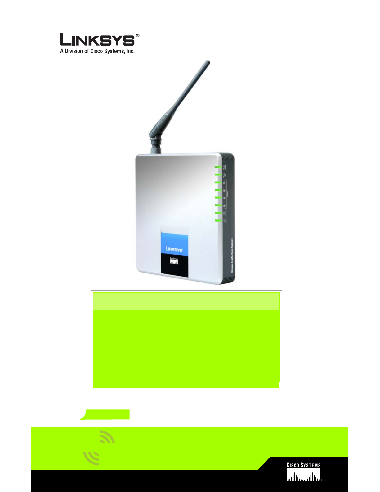
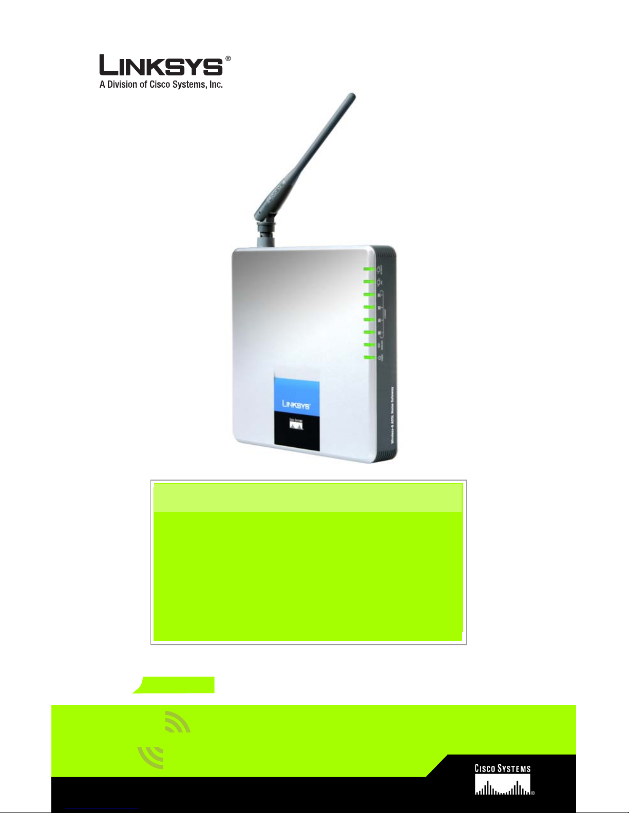
WAG200G (EU)
ADSL Home Gateway
Wireless-G
Package Contents
• Wireless-G ADSL Home Gateway
• User Guide on CD-ROM
• Ethernet Network Cable
• Phone Cable
• Power Adapter
• Microfilter or splitter (not supplied with
all models)
• Quick Installation
GHz
2
802.11g
4
,
Page 2

2
1
In Step 1, you will connect the
Gateway to your ADSL line and to
the computers in your home or
business.
First, make sure that all the devices
that you’ll be working with are
powered down, including your PCs
and the Gateway.
A Connect one end of the
provided phone cable to the
wall jack with ADSL service.
NOTE: To avoid interference,
you may need to place
a microfilter or splitter
between the phone
cable and wall jack.
Contact your service
provider for more
information. (If you use
ISDN, then you do not
need a microfilter.)
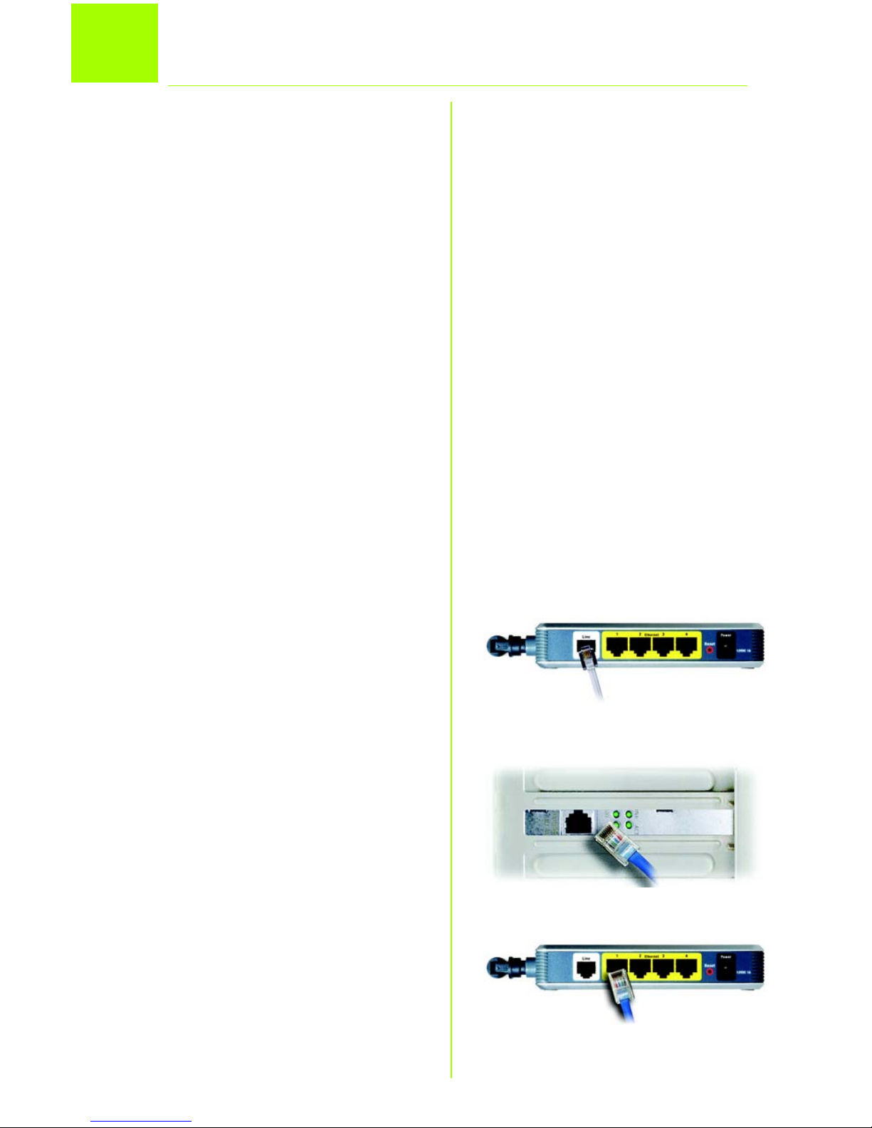
B Connect the other end of the
phone cable to the LINE port
that is on the back of the
Gateway. (Figure B)
C Connect one end of the
provided Ethernet cable to
your PC’s Ethernet adapter
(Figure C1). Connect the other
end of the cable to one of the
Ethernet ports on the back of
the Gateway (Figure C2).
Connect the ADSL Home Gateway
B
C1
C2
Page 3

3
Repeat this process for every
PC that you want to connect to
the Gateway.
If you are connecting more
than four PCs to the Gateway,
you will also need to connect
a hub or switch to the
Gateway.
NOTE: If your PC’s Ethernet
adapter is not set up,
refer to the Ethernet
adapter’s user guide for
more information.
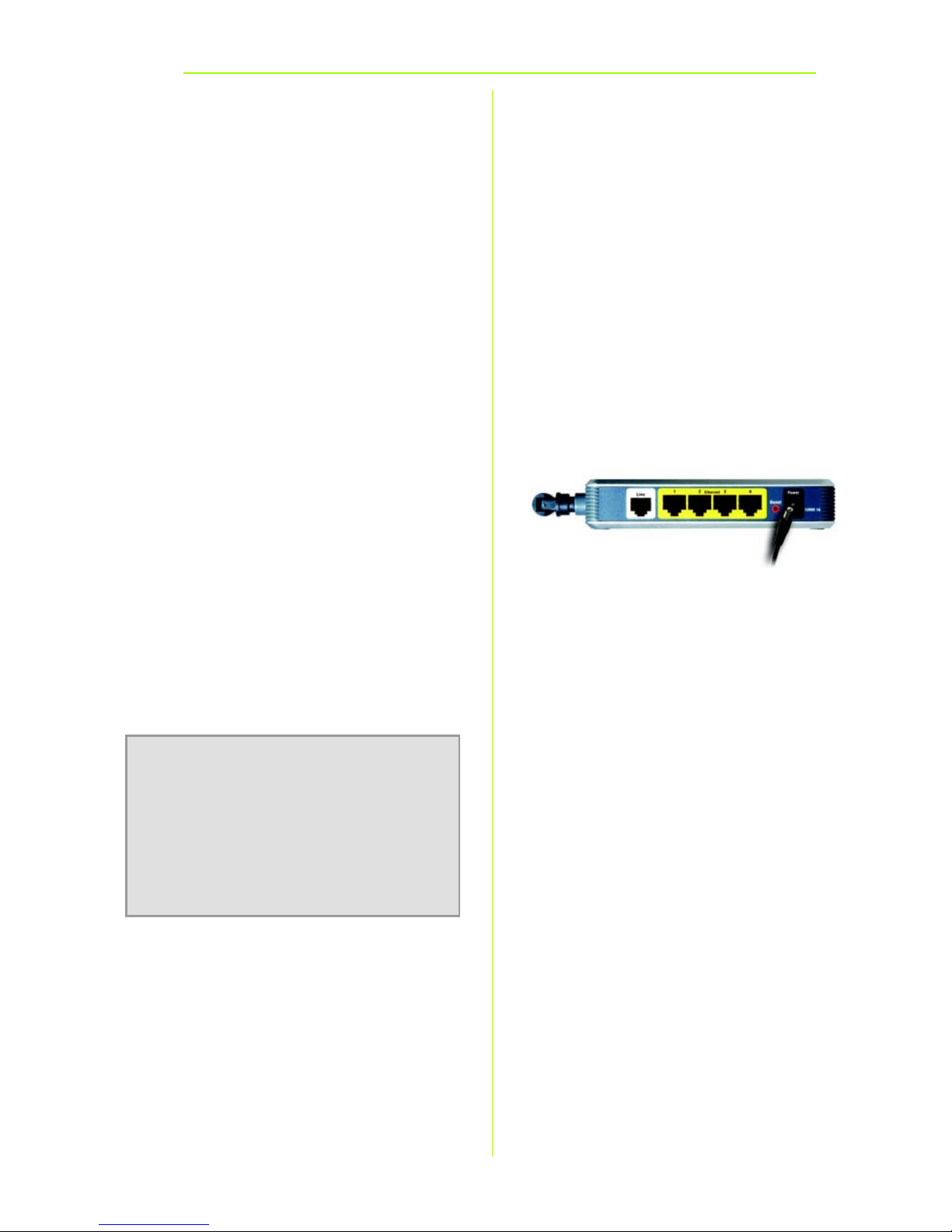
D Connect the power adapter to
the Gateway. Connect the
power adapter to the electrical
outlet. (Figure D)
E Turn on the Gateway. Then,
turn on the first PC that you
want to use to configure the
Gateway.
Proceed to Step 2: Configure the
ADSL Home Gateway.
D
IMPORTANT: Make sure you only
place the microfilter or splitter
between the phone and the wall
jack and not between the Gateway
and the wall jack. Otherwise your
ADSL will not connect.
Page 4

4
2
In Step 2, you will configure your
Linksys Wireless-G ADSL Home
Gateway to be able to gain access
to the Internet through your Internet
Service Provider (ISP). You will need
the setup information provided by
your ADSL ISP. If you do not have this
information, please contact them
before proceeding.
The instructions from your ISP tell you
how to set up your PC for Internet
access. Because you are now using
the Gateway to share Internet
access among several computers,
you will use the setup information to
configure the Gateway instead of
your PC.
NOTE: You only need to
configure the Gateway
once using the first
computer you set up.
A Open your web browser. (You
may get an error message at
this point. Continue following
these directions.) Enter
http://192.168.1.1 in the web
browser’s Address field. Press
the Enter key.
B An Enter Network Password
window, shown in Figure B, will
appear (Windows XP users will
see a Connect to 192.168.1.1
window). Enter admin in
lowercase letters in the User
Name field, and enter admin
Configure the ADSL Home Gateway
B
Page 5
5
in lowercase letters in the
Password field (admin is the
default user name and
password.) Then, click the OK
button.
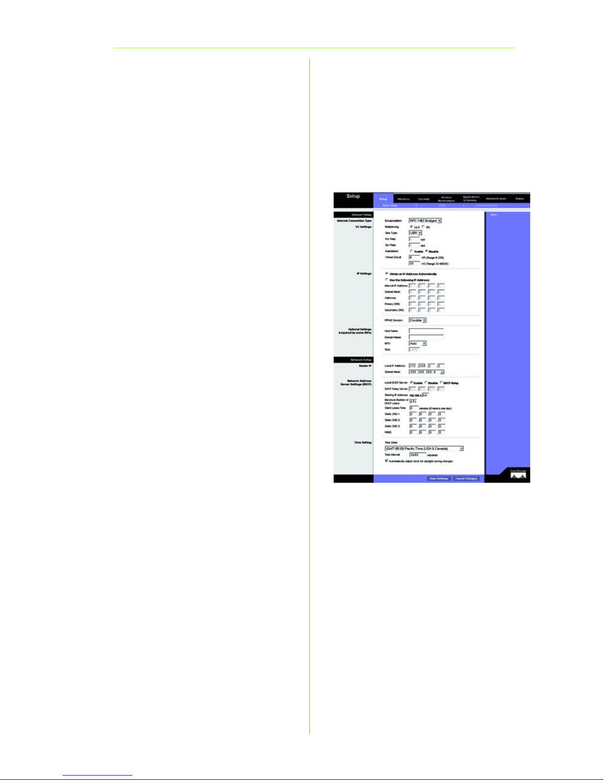
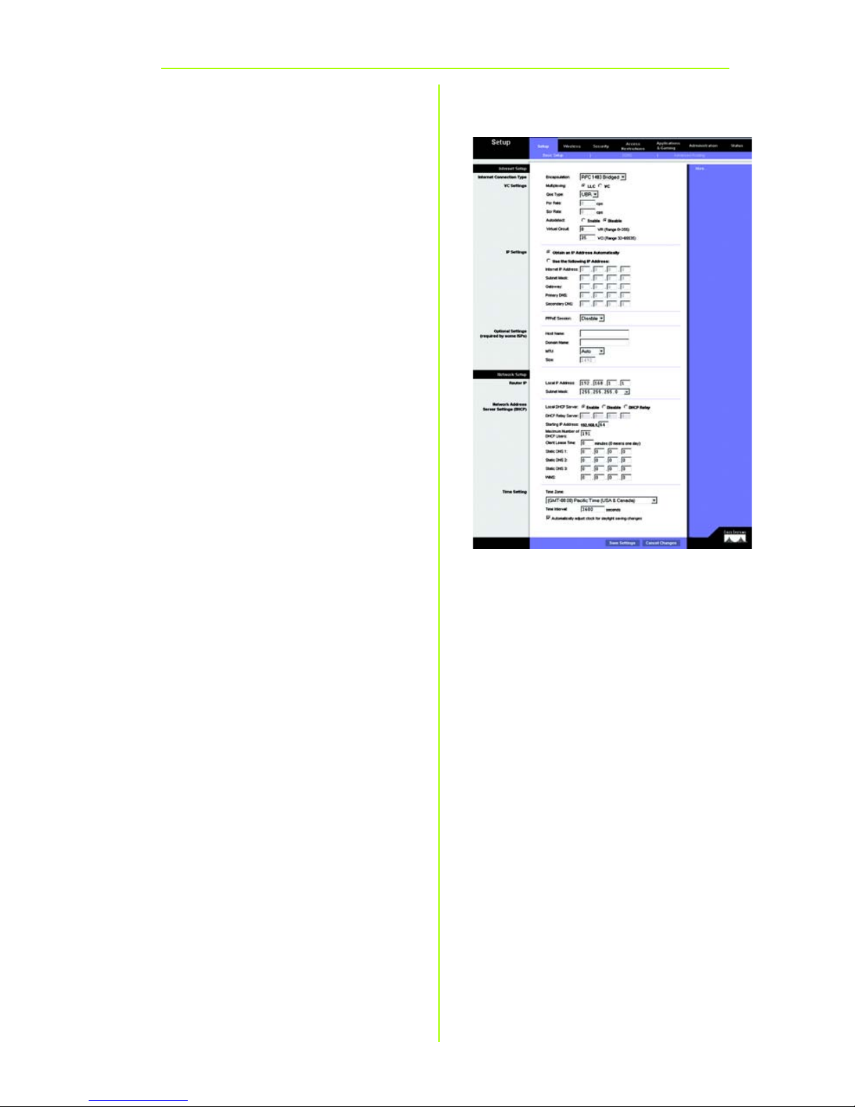
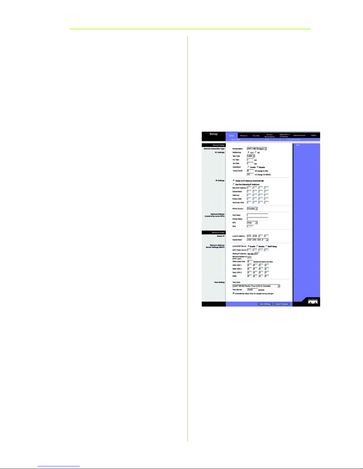
C The Basic Setup screen will
appear with the Setup tab
selected. (Figure C) Based on
the setup instructions from your
ISP, you may need to provide
the following information.
Virtual Circuit (VPI and VCI):
These fields consist of two
items: VPI (Virtual Path Identifier)
and VCI (Virtual Channel
Identifier). Your ISP will provide
the correct settings for each
field.
D Encapsulation: This Gateway
supports multiple settings for
the Encapsulation. The most
common Encapsulation
methods are described below.
All methods are included in the
User Guide (English only) on the
CD-ROM.
The settings required will
depend on the Encapsulation
chosen here. Your ISP will
provide the correct settings.
C
Page 6
6
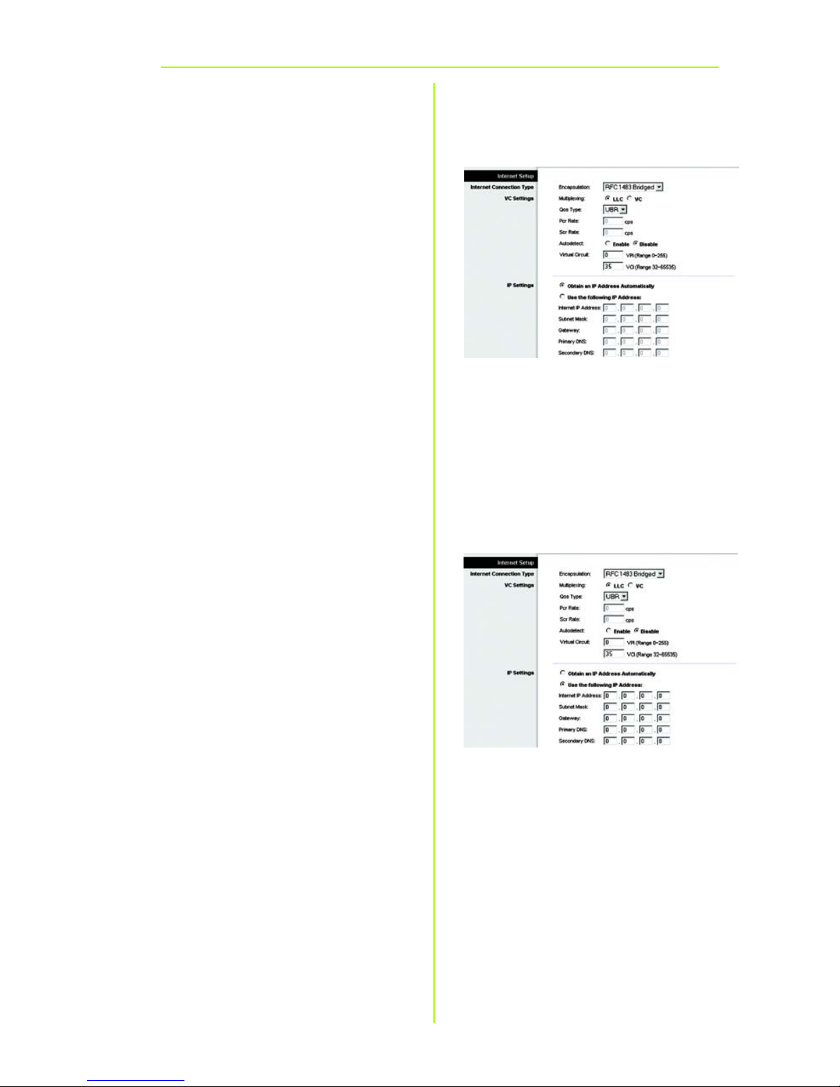
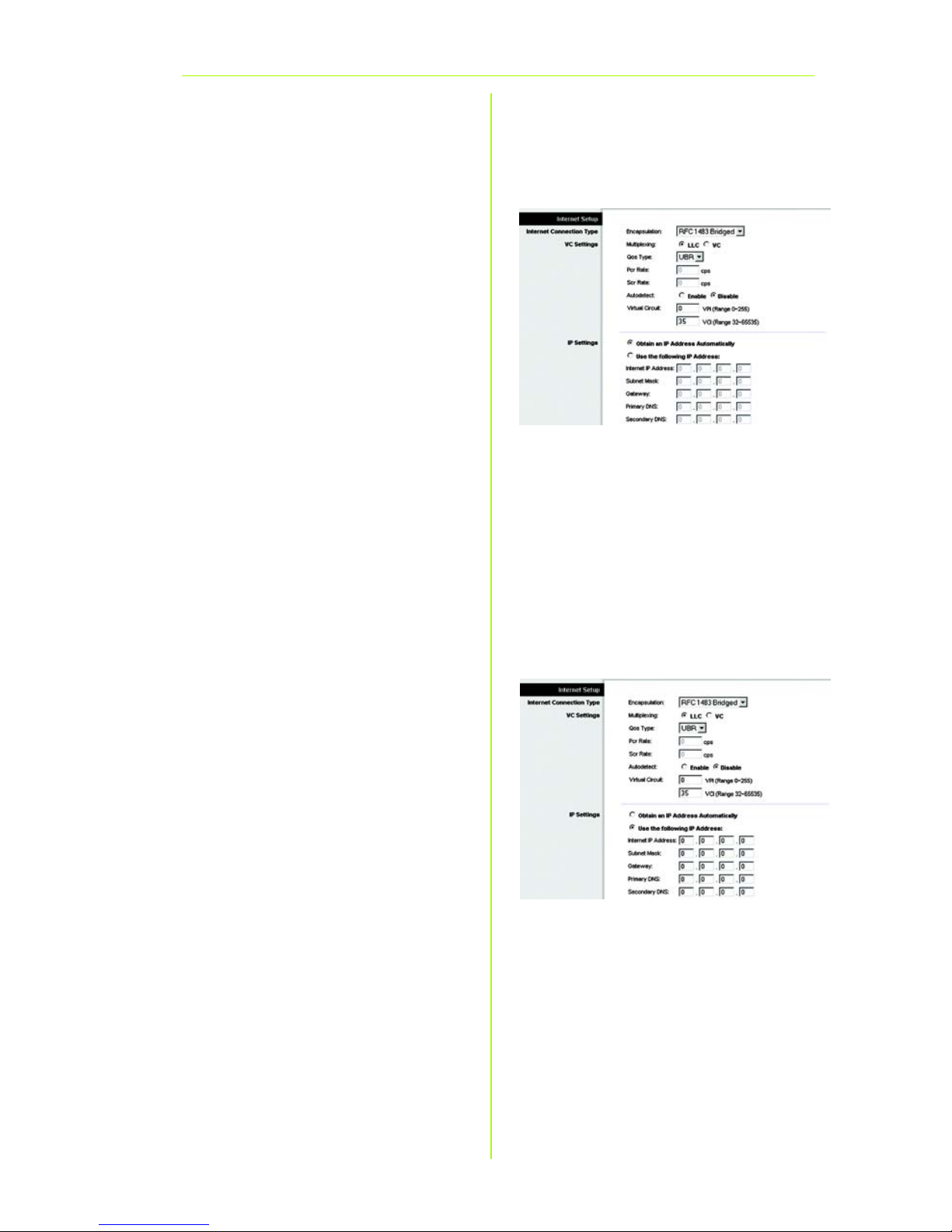
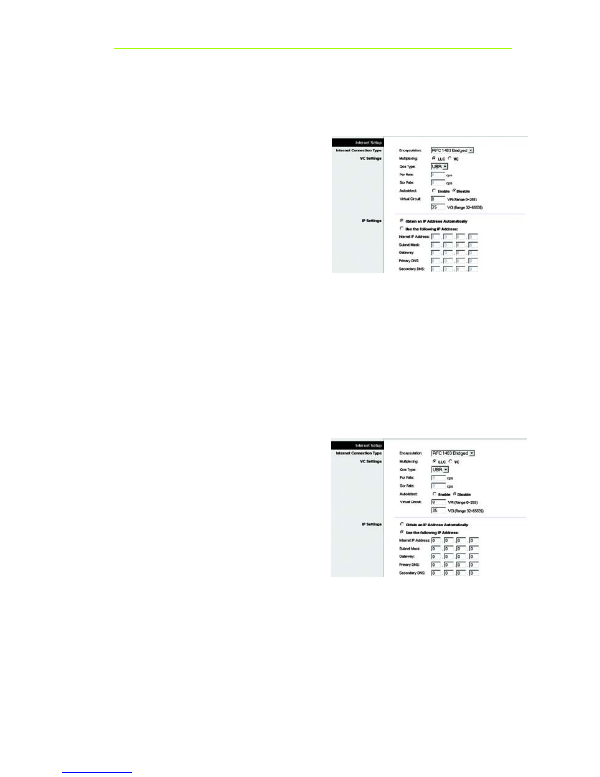
Dynamic
1 RFC 1483 Bridged
Dynamic IP Address
If your ISP says that you are
connecting through a dynamic IP
address (Figure D1), perform these
steps:
a Select RFC 1483 Bridged for
the Encapsulation.
b Select Obtain an IP Address
Automatically for the IP Setting.
c Click the Save Settings button
to save the settings.
Static IP Address
If your ISP says that you are
connecting through a static or fixed
IP address (Figure D2), perform these
steps:
a Select RFC 1483 Bridged for
the Encapsulation.
b Select Use the following IP
Address as the IP Setting.
c Enter the IP Address and the
Subnet Mask.
d Enter the Default Gateway
address.
D1
Static
D2
Page 7
7
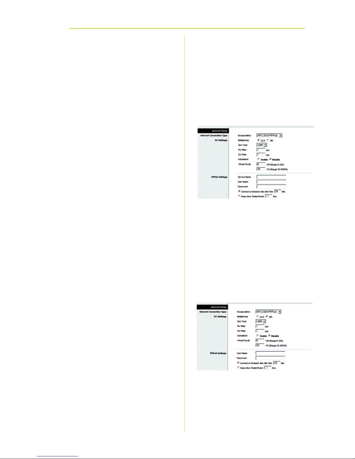
PPPoE
PPPoA
e Enter the DNS in the Primary
and/or Secondary fields. You
need to enter at least one DNS
address.
f Click the Save Settings button
to save the settings.
2 RFC 2516 PPPoE or RFC 2364
PPPoA
If your ISP says that you are
connecting through PPPoE (Figure
D3) or PPPoA (Figure D4), or if you
normally enter a user name and
password to access the Internet,
perform these steps:
a Select PPPoE or PPPoA as
appropriate for the
Encapsulation.
b If you selected PPPoE, enter
the Service Name (if required).
c Enter the User Name.
d Enter the Password.
e Select Keep Alive if you always
want to be connected to your
ISP, or select Connect on
Demand if you are charged
for the time that you are
connected to your ISP.
f Click the Save Settings button
to save the settings.
D3
D4
Page 8

8
E If you haven’t already done so,
click the Save Settings button
to save your Setup settings.
Close the web browser.
F For Wireless Configuration:
Refer to the User Guide (English
only) for detailed instructions
on how to configure your
Gateway for your wireless
network. Linksys recommends
changing your wireless settings
from the defaults and enabling
the appropriate security
options.
G Congratulations! You’ve
successfully configured the
Gateway. Test the setup by
opening your web browser
from any computer and
entering:
www.linksys.com/registration
H If you are unable to reach our
website, you may want to
review the installation and
configuration sections in this
Quick Installation or refer to the
Troubleshooting section of the
User Guide.
WAG200G-EU-QIG-60311NC TE
Linksys is a registered trademark or trademark of
Cisco Systems, Inc. and/or its affiliates in the U.S.
and certain other countries. Copyright © 2006
Cisco Systems, Inc. All rights reserved.
For additional information or troubleshooting
help, refer to the User Guide on the CD-ROM
or the Technical Support Insert. You can also
e-mail for further support.
Website
http://www.linksys.com/international
Product Registration
http://www.linksys.com/registration
IMPORTANT: Once the Gateway is
configured, wireless security,
either WEP or WPA, should be
configured to prevent security
breaches in your network.
Page 9
Modelnr.
Modelnr.
Trådløs
Installationsvejledning
Wireless
1
Installationsvejledning
Modelnr.
WAG200G (DK)
ADSL-gateway til hjemmet
Trådløs-G
Pakkens indhold
• Trådløs-G ADSL-gateway til hjemmet
• Brugervejledning på cd-rom
• Ethernet-kabel
• Telefonledning
• Strømforsyning
• Mikrofilter eller fordeler (følger ikke
med alle modeller)
• Installationsvejledning
GHz
2
802.11g
4
,
Page 10

2
1
I trin 1 tilslutter du gatewayen til
ADSL-linjen og til computerne i dit
hjem/din virksomhed.
Kontroller først, at alle de involverede
enheder er slukket, herunder dine
pc'er og gatewayen.
A Tilslut den ene ende af den
medfølgende telefonledning til
ADSL-vægstikket.
BEMÆRK: Det kan være
nødvendigt at placere
et mikrofilter eller en
fordeler mellem
telefonledningen og
vægstikket for at undgå
interferens. Kontakt din
tjenesteudbyder for at
få yderligere
oplysninger.
B Tilslut den anden ende af
telefonledningen til LINE-porten
bag på gatewayen. (Figur B)
C Tilslut den ene ende af det
medfølgende Ethernet-kabel til
pc'ens Ethernet-adapter
(Figur C1). Tilslut den anden
ende af kablet til en af Ethernetportene bag på gatewayen
(Figur C2). Gentag denne
fremgangsmåde for alle de
pc'er, du vil tilslutte til
gatewayen.
Tilslutning af ADSL-gatewayen
B
C
1
C2
Page 11

3
Hvis du tilslutter mere end fire
pc'er til gatewayen, skal du også
tilslutte en hub eller switch til
gatewayen.
BEMÆRK: Hvis pc'ens Ethernet-
adapter ikke er
konfigureret, skal du se
brugervejledningen til
Ethernet-adapteren
for at få yderligere
oplysninger.
D Tilslut strømforsyningen til
gatewayen. Tilslut strømforsyningen
til stikkontakten. (Figur D)
E Tænd gatewayen. Tænd
derefter den første pc, som du
vil bruge til konfiguration af
gatewayen.
Fortsæt til trin 2: Konfiguration af
ADSL-gatewayen.
VIGTIGT: Sørg for kun at placere
mikrofilteret eller fordeleren
mellem telefonen og vægstikket og
ikke mellem gatewayen og
vægstikket. I modsat fald kan du
ikke bruge ADSL-linjen.
D
Page 12

4
2
I trin 2 konfigurerer du Linksys Trådløs-G
ADSL-gatewayen, så du kan oprette
adgang til internettet via din
internetudbyder. Du skal have
konfigurationsoplysningerne af din
ADSL-udbyder. Hvis du ikke har disse
oplysninger, skal du kontakte
udbyderen, før du fortsætter.
I vejledningen fra din internetudbyder
kan du læse, hvordan du konfigurerer
pc'en til internetadgang. Da du nu
anvender gatewayen til deling af
internetadgang mellem flere
computere, skal du konfigurere
gatewayen i stedet for pc'en ved
hjælp af konfigurationsvejledningen.
BEMÆRK: Du skal blot konfigurere
gatewayen én gang
ved hjælp af den
første computer, du
har installeret.
A Åbn webbrowseren. (Der vises
muligvis en fejlmeddelelse.
Fortsæt, idet du følger disse
anvisninger). Skriv http://
192.168.1.1 i feltet Address
(Adresse) i webbrowseren. Tryk
på Enter.
B Vinduet Enter Network Password
(Skriv adgangskoden til
netværket) vises, se Figur B
(Windows XP-brugere får vist et
vindue, hvor de bliver bedt om
at oprette forbindelse til
192.168.1.1). Indtast admin
med små bogstaver i feltet User
Name (Brugernavn), og indtast
Konfiguration af ADSL-gatewayen
B
Page 13

5
admin med små bogstaver i
feltet Password (Adgangskode)
(admin er standardbrugernavnet
og -adgangskoden.) Klik derefter
på knappen OK.
C Skærmbilledet Basic Setup vises
med fanen Setup valgt. (Figur C)
Afhængigt af
konfigurationsvejledningen fra
din internetudbyder skal du
muligvis angive følgende
oplysninger.
VPI og VCI (Virtual Circuit): Disse
felter består af to punkter: VPI
(Virtual Path Identifier) og VCI
(Virtual Channel Identifier). Få de
korrekte indstillinger til felterne hos
din internetudbyder.
D Indkapsling: Denne gateway
understøtter flere indstillinger for
indkapsling. De meste anvendte
indkapslingsmetoder er
beskrevet nedenfor. Alle
metoderne er beskrevet i
brugervejledningen (kun på
engelsk) på cd-rom'en.
De nødvendige indstillinger
afhænger af den
indkapslingsmetode, der er valgt
her. Få de korrekte indstillinger
hos din internetudbyder.
Modelnr.
C
Page 14

6
Dynamisk
1 RFC 1483 Bridged
Dynamisk IP-adresse
Hvis din internetudbyder har oplyst, at
du opretter forbindelse via en
dynamisk IP-adresse (Figur D1), skal du
følge nedenstående
fremgangsmåde:
a Vælg RFC 1483 Bridged som
indkapslingsmetode.
b Vælg Obtain an IP Address
Automatically som IP-indstilling.
c Klik på knappen Save Settings
for at gemme indstillingerne.
Statisk IP-adresse
Hvis din internetudbyder har oplyst, at
du opretter forbindelse via en statisk
eller fast IP-adresse (Figur D1), skal du
følge nedenstående
fremgangsmåde:
a Vælg RFC 1483 Bridged som
indkapslingsmetode.
b Vælg Use the following IP
Address som IP-indstilling.
c Indtast IP-adressen og
undernetmasken.
d Indtast adressen på
standardgatewayen.
Hurtig installation
D1
Statisk
D2
Page 15

7
PPPoE
PPPoA
e Indtast DNS-adressen i feltet
Primary og/eller Secondary.
Du skal indtaste mindst én
DNS-adresse.
f Klik på knappen Save Settings
for at gemme indstillingerne.
2 RFC 2516 PPPoE eller RFC 2364
PPPoA
Hvis din internetudbyder har oplyst, at
du opretter forbindelse via PPPoE (Figur
D3) eller PPPoA (Figur D4), eller hvis du
normalt indtaster et brugernavn og en
adgangskode for at oprette
forbindelse til internettet, skal du følge
nedenstående fremgangsmåde:
a Vælg PPPoE eller PPPoA som
indkapslingsmetode.
b Hvis du har valgt PPPoE, skal du
intaste tjenestenavnet (hvis det
er påkrævet).
c Indtast brugernavnet.
d Indtast adgangskoden.
e Vælg Connect on Demand,
hvis du betaler minuttakst eller
Keep Alive, hvis du betaler en
fast afgift.
f Klik på knappen Save Settings
for at gemme indstillingerne.
D3
D4
Page 16

8
E Hvis du ikke allerede har gjort
det, skal du klikke på knappen
Save Settings for at gemme
dine konfigurationsindstillinger.
Luk webbrowseren.
F Trådløs konfiguration: Se
brugervejledningen (kun på
engelsk) for at få detaljerede
oplysninger om, hvordan du
konfigurerer gatewayen til dit
trådløse netværk. Linksys
anbefaler, at du ændrer de
trådløse indstillinger, så du ikke
bruger standardindstillingerne,
og aktiverer de relevante
sikkerhedsindstillinger.
G Tillykke! Du er færdig med at
konfigurere gatewayen. Test
konfigurationen ved at åbne
webbrowseren på en computer
og indtaste følgende:
www.linksys.com/registration
H Hvis du ikke kan oprette
forbindelse til vores websted, kan
du prøve igen at gennemgå
afsnittene om installation og
konfiguration i denne
installationsvejledning, eller du
kan se afsnittet om fejlfinding i
brugervejledningen.
WAG200G-DK-QIG-60314NC TE
Linksys er et registreret varemærke tilhørende
Cisco Systems, Inc. og/eller Cisco Systems
associerede selskaber i USA og visse andre andre
lande. Copyright © 2006 Cisco Systems, Inc. Alle
rettigheder forbeholdes.
Yderligere oplysninger eller hjælp til
fejlfinding finder du i brugervejledningen på
cd-rom'en eller ved at kontakte Teknisk
support (se arket om teknisk support).
Websted
http://www.linksys.com /international
Registrering
http://www.linksys.com/registration
VIGTIGT: Så snart gatewayen er
konfigureret, bør den trådløse
sikkerhed (enten WEP eller WPA)
konfigureres for at undgå, at der
opstår åbninger i dit netværk.
Page 17

Model No.
Model No.
Wireless
Quick Installation Guide
Wireless
Kurzanleitung
Modell
1
WAG200G (DE)
ADSL-Home-Gateway
Wireless-G
Lieferumfang
• Wireless-G ADSL-Home-Gateway
• Benutzerhandbuch auf CD-ROM
• Ethernet-Netzwerkkabel
• Telefonkabel
• Netzteil
• Mikrofilter (nicht im Lieferumfang aller
Modellnummern enthalten)
• Kurzanleitung
GHz
2
802.11g
4
,
Page 18

2
1
In Schritt 1 schließen Sie das Gateway
an Ihre ADSL-Verbindung und die
Computer in Ihrer Heim- oder
Unternehmensumgebung an.
Überprüfen Sie zuerst, ob alle Geräte,
mit denen Sie arbeiten (einschließlich
PCs und Gateway), ausgeschaltet sind.
A Schließen Sie ein Ende des
beigelegten Telefonkabels an die
Wandbuchse mit dem ADSLDienst an.
HINWEIS: Zur Vermeidung von
Störungen sollten Sie
u. U. einen Mikrofilter
oder „Verteiler“ zwischen
dem Telefonkabel und
der Wandbuchse
einsetzen. Weitere
Informationen erhalten
Sie beim InternetDienstanbieter.
B Schließen Sie das andere Ende
des Telefonkabels an den LINEPort an der Rückseite des
Gateways an. (Abbildung B)
C Schließen Sie ein Ende des
beigelegten Ethernet-Kabels an
den Ethernet-Adapter des PCs an
(Abbildung C1). Schließen Sie das
andere Ende des Kabels an einen
der Ethernet-Ports an der
Rückseite des Gateways an
(Abbildung C2). Wiederholen Sie
diesen Vorgang für jeden PC, der
an das Gateway angeschlossen
werden soll.
Anschließen des ADSL-Gateways
B
C
1
C2
Page 19

3
Wenn mehr als vier PCs an das
Gateway angeschlossen werden
sollen, müssen Sie außerdem
einen Hub oder Switch an das
Gateway anschließen.
HINWEIS: Wenn der Ethernet-
Adapter des Computers
nicht eingerichtet ist,
finden Sie dazu weitere
Informationen im
Benutzerhandbuch zum
Ethernet-Adapter.
D Schließen Sie den
Netzteil an das
Gateway an. Stecken Sie den
Netzteil in die
Steckdose (Abbildung D).
E Schalten Sie das Gateway ein.
Schalten Sie dann den ersten PC
ein, mit dem das Gateway
konfiguriert werden soll.
Fahren Sie mit Schritt 2,
„Konfigurieren des ADSL-
Gateways“, fort.
WICHTIG: Setzen Sie den Mikrofilter
oder „Verteiler“ nur zwischen dem
Telefon und der Wandbuchse und nicht
zwischen dem Gateway und der
Wandbuchse ein. Andernfalls schlägt
die ADSL-Verbindung fehl.
D
Page 20

4
2
In Schritt 2 konfigurieren Sie das Linksys
Wireless-G ADSL-Home-Gateway für den
Zugriff auf das Internet über Ihren ISP. Sie
benötigen hierzu die SetupInformationen Ihres ADSL-ISPs. Wenn Sie
nicht über diese Informationen
verfügen, wenden Sie sich an Ihren ISP,
bevor Sie beginnen.
Die Anweisungen von Ihrem ISP geben
an, wie Sie Ihren Computer für den
Internetzugriff einrichten müssen. Da Sie
ab jetzt das Gateway verwenden, um
über mehrere Computer gleichzeitig auf
das Internet zuzugreifen, wenden Sie die
Setup-Informationen zur Konfiguration
des Gateways statt des Computers an.
HINWEIS: Sie müssen das
Gateway nur einmal auf
einem der
eingerichteten
Computer konfigurieren.
A Öffnen Sie den Web-Browser.
(Unter Umständen wird eine
Fehlermeldung angezeigt. Fahren
Sie einfach mit diesen
Anweisungen fort.) Geben Sie
http://192.168.1.1 im Feld
Adresse des Browsers ein. Drücken
Sie die Eingabetaste.
B Das Fenster Netzkennwort
eingeben wird wie in Abbildung B
angezeigt (unter Windows XP wird
das Fenster Verbindung zu
192.168.1.1 herstellen
angezeigt). Geben Sie admin in
Kleinbuchstaben im Feld
Benutzername sowie ebenfalls
admin im Feld Kennwort ein
(„admin“ ist der
Standardbenutzername und das
Standardkennwort). Klicken Sie
dann auf OK.
Konfigurieren des ADSL-Gateways
B
Page 21
5
C Das Fenster Basic Setup
(Grundlegende Einrichtung) wird
mit ausgewählter Registerkarte
Setup angezeigt (Abbildung C).
Je nach den Setup-Informationen
von Ihrem ISP müssen Sie unter
Umständen die folgenden
Informationen eingeben:
Virtual Circuit (Virtueller Kreis): Für
diese Option sind zwei
Einstellungen erforderlich, VPI
(Virtual Path Identifier; Virtueller
Pfadidentifizierer) und VCI (Virtual
Channel Identifier; Virtueller
Kanalidentifizierer). Die korrekten
Einstellungen erhalten Sie von
Ihrem ISP.
D Encapsulation (Kapselung):
Dieses Gateway unterstützt
verschiedene
Kapselungseinstellungen. Die
bekanntesten
Kapselungsmethoden werden
nachfolgend beschrieben.
Sämtliche Methoden werden im
Benutzerhandbuch (nur auf
Englisch verfügbar) auf der CDROM beschrieben.
Die erforderlichen Einstellungen
hängen von der hier
ausgewählten
Kapselungsmethode ab. Die
korrekten Einstellungen erhalten
Sie von Ihrem ISP.
C
Page 22
6
1 RFC 1483 Bridged (RFC 1483-
Überbrückung)
Dynamische IP Adresse
Wenn Sie laut ISP über eine dynamische IPAdresse verbunden sind (Abbildung D1),
führen Sie die folgenden Schritte aus:
a Wählen Sie als Kapselungsmethode
RFC 1483 Bridged (RFC 1483Überbrückung) aus.
b Wählen Sie Obtain an IP Address
Automatically (IP-Adresse
automatisch beziehen) als IPEinstellung aus.
c Klicken Sie auf die Schaltfläche
Save Settings (Einstellungen
speichern), um die Einstellungen zu
speichern.
Statische IP-Adresse
Wenn Sie laut ISP über eine statische oder
feste IP-Adresse verbunden sind
(Abbildung D2), führen Sie die folgenden
Schritte aus:
a Wählen Sie als Kapselungsmethode
RFC 1483 Bridged (RFC 1483Überbrückung) aus.
b Wählen Sie Use the following IP
Address (Folgende IP-Adresse
verwenden) als IP-Einstellung aus.
c Geben Sie die IP-Adresse und die
Subnetzmaske ein.
d Geben Sie die Standard-
Gatewayadresse ein.
D1
D2
Dynamische IP-Adresse
Statische IP-Adresse
Page 23

7
e Geben Sie die DNS-Adressen in die
Felder Primary DNS (Primärer DNS)
und Secondary DNS (Sekundärer
DNS) ein. Sie müssen mindestens
eine DNS-Adresse eingeben.
f Klicken Sie auf die Schaltfläche
Save Settings (Einstellungen
speichern), um die Einstellungen zu
speichern.
2 RFC 2516 PPPoE oder RFC 2364
PPPoA
Wenn Sie laut ISP über PPPoE (Abbildung
D3) oder PPPoA (Abbildung D4) eine
Verbindung zum Internet herstellen oder
normalerweise einen Benutzernamen und
ein Kennwort eingeben, führen Sie die
folgenden Schritte aus:
a Wählen Sie PPPoE oder PPPoA als
Kapselungsmethode aus.
b Geben Sie bei Auswahl von PPPoE
ggf. den Dienstnamen ein.
c Geben Sie den Benutzernamen
unter User Name ein.
d Geben Sie das Kennwort unter
Password ein.
e Wählen Sie für eine ständige
Verbindung zu Ihrem ISP Keep Alive
(Verbindung aufrecht halten), oder
wählen Sie Connect on Demand (Bei
Bedarf verbinden), falls die
Verbindungszeit mit Ihrem ISP
gebührenpflichtig ist.
f Klicken Sie auf die Schaltfläche
Save Settings (Einstellungen
D3
D4
PPPoE
PPPoA
Page 24

8
speichern), um die Einstellungen zu
speichern.
E Klicken Sie ggf. auf die Schaltfläche
Save Settings (Einstellungen
speichern), um die SetupEinstellungen zu speichern.
Schließen Sie den Web-Browser.
F Wenn Sie eine drahtlose
Konfiguration durchführen, finden
Sie genaue Anweisungen zur
Konfiguration des Gateways für Ihr
Wireless-Netzwerk im
Benutzerhandbuch (nur auf
Englisch verfügbar). Es wird
empfohlen, die Standardwerte für
die Wireless-Einstellungen zu ändern
und entsprechende
Sicherheitsoptionen zu aktivieren.
G Herzlichen Glückwunsch! Das
Gateway wurde erfolgreich
konfiguriert. Überprüfen Sie die
Installation, indem Sie auf einem
der Computer den Web-Browser
öffnen und www.linksys.com/
registration eingeben.
H Wenn diese Website nicht
aufgerufen werden kann, lesen Sie
die Abschnitte zur Installation und
Konfiguration in dieser Kurzanleitung
erneut bzw. lesen Sie den Abschnitt
zur Fehlerbehebung im
Benutzerhandbuch.
WAG200G-DE-QIG-60314NC TE
Weitere Informationen und Anleitungen zur
Fehlerbehebung finden Sie im Benutzerhandbuch
auf der Installations-CD-ROM. Informationen zur
Kontaktaufnahme mit dem technischen
Kundendienst finden Sie in der technischen
Support-Beilage.
Website
http://www.linksys.com/international
Registrierung
http://www.linksys.com/registration
Linksys ist eine eingetragene Marke bzw. eine Marke
von Cisco Systems, Inc. und/oder deren
Zweigunternehmen in den USA und anderen Ländern.
Copyright © 2006 Cisco Systems, Inc. Alle Rechte
vorbehalten.
WICHTIG: Sobald das Gateway
konfiguriert ist, muss die WirelessSicherheit (WEP oder WPA)
konfiguriert werden, sodass keine
Sicherheitslücken in Ihrem
Netzwerk bestehen.
Page 25
Model No.
Model No.
Wireless
Quick Installation Guide
Wireless
1
Instalación rápida
Modelo
WAG200G (ES)
Puerta de enlace
Wireless-G
Contenido del paquete
• Puerta de enlace doméstica ADSL Wireless-G
• Guía del usuario en CD-ROM
• Cable de red Ethernet
• Cable telefónico
• Adaptador de corriente
• Microfiltro(s) (no proporcionados con todos los
números de modelo)
• Instalación rápida
GHz
2
802.11g
4
,
doméstica ADSL
Page 26
2
1
En el paso 1, debe conectar la puerta
de enlace a la línea ADSL y a los
ordenadores de casa o de la oficina.
En primer lugar, asegúrese de que
todos los dispositivos con los que va a
trabajar están apagados, incluyendo
los PC y la puerta de enlace.
A Conecte un extremo del cable
telefónico proporcionado al
jack de pared provisto del
servicio ADSL.
NOTA: Para evitar
interferencias, puede
que necesite utilizar un
microfiltro o un divisor
entre el cable telefónico
y el jack. Póngase en
contacto con el
proveedor de servicios
para obtener más
información.
B Conecte el otro extremo del
cable telefónico al puerto LINE
situado en la parte posterior de
la puerta de enlace. (Figura B)
C Conecte un extremo del cable
Ethernet proporcionado al
adaptador Ethernet del PC
(figura C1). Conecte el otro
extremo del cable a uno de los
puertos Ethernet de la parte
posterior de la puerta de enlace
(figura C2). Repita este proceso
para cada PC que desee
conectar a la puerta de enlace.
Conecte la puerta de enlace ADSL
B
C
1
C2
Page 27
3
Si va a conectar más de cuatro
PC a la puerta de enlace,
también deberá conectar un
concentrador o conmutador a
la misma.
NOTA: Si el adaptador Ethernet
del ordenador no está
configurado, consulte la
guía del usuario del
mismo para obtener
más información.
D Conecte el adaptador de
corriente a la puerta de enlace.
Conecte el adaptador de
corriente a la toma de corriente.
(Figura D)
E Encienda la puerta de enlace.
A continuación, encienda el
primer PC que utilizó para
configurar la puerta de enlace.
Siga en el paso 2: Configure la
puerta de enlace ADSL.
IMPORTANTE: Asegúrese de que sólo
sitúa el microfiltro o divisor entre el
teléfono y el jack de pared y no entre
la puerta de enlace y dicho jack. De lo
contrario, la línea ADSL no realizará la
conexión.
D
Page 28

4
2
En el paso 2, debe configurar la
puerta de enlace doméstica ADSL
Wireless-G de Linksys para poder
acceder a Internet mediante un
proveedor de servicios de Internet
(ISP). Necesitará la información
proporcionada por el ISP de ADSL. Si
no la tiene, póngase en contacto con
el ISP antes de continuar.
Las instrucciones del ISP?le indican
cómo configurar el acceso a Internet.
Debido a que va a utilizar la puerta
de enlace para compartir el acceso
a Internet entre varios ordenadores,
debe utilizar la información de
configuración para configurarla en
lugar del PC.
NOTA: Sólo tiene que
configurar la puerta de
enlace una vez
mediante el primer
ordenador que vaya a
configurar.
A Abra el explorador Web. (En este
punto, puede que reciba un
mensaje de error. Siga las
instrucciones normalmente.)
Escriba http://192.168.1.1/ en el
campo Dirección del
explorador Web. Pulse la tecla
Intro.
B Aparece la ventana Escribir
contraseña de red que se
puede ver en la figura B (los
usuarios de Windows XP verán
una ventana de conexión a
192.168.1.1). Escriba admin en
minúsculas en el campo
Configure la puerta de enlace ADSL
B
Page 29
5
Nombre de usuario y de nuevo
en el campo Contraseña
(admin es el nombre de usuario
y la contraseña
predeterminados). A
continuación, haga clic en el
botón Aceptar.
C Aparece la pantalla Basic Setup
(Configuración básica) con la
ficha Setup (Configurar)
seleccionada. (Figura C) Según
las instrucciones de
configuración del ISP, quizá
necesite proporcionar la
siguiente información.
Virtual Circuit (Circuito virtual; VPI
y VCI): este campo consta de
dos elemenos: VPI (Identificador
de ruta virtual) y VCI
(Identificador de canal virtual). El
ISP le proporcionará los
parámetros correctos para
cada campo.
D Encapsulation (Encapsulación):
esta puerta de enlace admite
varios parámetros de
encapsulación. Los métodos
más habituales son los descritos
a continuación. Todos los
métodos se detallan en la guía
del usuario (sólo en ingles) del
CD-ROM.
Los parámetros necesarios
dependen de la encapsulación
seleccionada. El ISP le
proporcionará los parámetros
correctos.
C
Page 30
6
1 RFC 1483 Bridged (RFC 1483
con puente)
Dynamic IP Address (Dirección
IP dinámica)
Si el ISP indica que su conexión se
realiza mediante una dirección IP
dinámica (figura D1), siga estos pasos:
a En Encapsulation
(Encapsulación), seleccione RFC
1483 Bridged (RFC 1483 con
puente).
b En IP Settings (Parámetros IP),
seleccione Obtain an IP Address
Automatically (Obtener una
dirección IP automáticamente).
c Haga clic en el botón Save
Settings (Guardar parámetros)
para guardar los parámetros.
Dirección IP estática
Si el ISP indica que su conexión se
realiza mediante una dirección IP
estática o fija (figura D2), siga estos
pasos:
a En Encapsulation
(Encapsulación), seleccione RFC
1483 Bridged (RFC 1483 con
puente).
b En IP Settings (Parámetros IP),
seleccione Use the following IP
Address (Usar la siguiente
dirección IP).
c Introduzca la dirección IP (IP
Address) y la máscara de subred
(Subnet Mask).
Instalación rápida
D1
D2
Dinámica
Estática
Page 31

7
d Introduzca la dirección de la
puerta de enlace
predeterminada (Default
Gateway).
e Introduzca la dirección DNS en
los campos correspondientes a
las direcciones DNS principal
(Primary) y secundaria
(Secondary). Debe introducir por
lo menos una dirección DNS.
f Haga clic en el botón Save
Settings (Guardar parámetros)
para guardar los parámetros.
2 RFC 2516 PPPoE o RFC 2364
PPPoA
Si el ISP le indica que la conexión se
realiza mediante PPPoE (figura D3) o
PPPoA (figura D4) o si tiene que
introducir un nombre de usuario y una
contraseña para acceder a Internet,
siga estos pasos:
a Seleccione PPPoE o PPPoA,
según corresponda, en
Encapsulation (Encapsulación).
b Si selecciona PPPoE, introduzca,
si es necesario, el nombre de
servicio (Service Name).
c Introduzca el nombre de usuario
(User Name).
d Introduzca la contraseña
(Password).
e Seleccione Keep Alive (Mantener
activo) si desea estar
continuamente conectado al ISP.
De lo contrario, seleccione
Connect on Demand (Conectar
D3
D4
PPPoE
PPPoA
Page 32

8
cuando se solicite) si debe pagar
todo el tiempo que esté
conectado al ISP.
f Haga clic en el botón Save
Settings (Guardar parámetros)
para guardar los parámetros.
E Si aún no lo ha hecho, haga clic
en el botón Save Settings
(Guardar parámetros) para
guardar los parámetros. Cierre el
explorador Web.
F Para configuración inalámbrica:
consulte la guía del usuario (sólo
en inglés) para obtener
instrucciones sobre la
configuración de la puerta de
enlace en una red inalámbrica.
Linksys recomienda modificar los
parámetros predeterminados de
la configuración inalámbrica y
activar las opciones de
seguridad adecuadas.
G Enhorabuena. Ha configurado la
puerta de enlace
correctamente. Compruebe la
configuración. Para ello, abra el
explorador Web desde cualquier
ordenador e introduzca
www.linksys.com/registration.
H Si no puede acceder a nuestra
página Web, quizá le interese
revisar las secciones de
instalación y configuración de
esta guía de instalación rápida o
consultar la sección
Troubleshooting (Resolución de
problemas) de la guía de
usuario.
WAG200G-ES-QIG-60314NC TE
Para obtener información adicional o ayuda
sobre solución de problemas, consulte la guía
del usuario en CD-ROM o consulte el suplemento
de asistencia técnica para obtener asistencia.
Página Web
http://www.linksys.com/international
Registro
http://www.linksys.com/registration
Linksys es una marca comercial registrada o marca
comercial de Cisco Systems, Inc. y/o sus filiales de
EE.UU. y otros países. Copyright © 2006 Cisco
Systems, Inc. Todos los derechos reservados.
IMPORTANTE: Una vez
configurado la puerta de enlace
se debe configurar la seguridad
inalámbrica, ya sea WEP o
WPA, para evitar que se
vulnere la seguridad de la red.
Page 33

Model No.
Model No.
Wireless
Quick Installation Guide
Sans fil
Guide d’installation rapide
Modèle
1
WAG200G (FR)
Modem routeur ADSL résidentiel
Sans fil-G
Contenu de l'emballage
• Modem routeur ADSL résidentiel sans fil G
• Guide de l'utilisateur sur CD-ROM
• Câble réseau Ethernet
• Câble téléphonique
• Adaptateur d'alimentation
• Microfiltre(s) (ne sont pas livrés avec certains modèles)
• Guide d'installation rapide
GHz
2
802.11g
4
,
Page 34

2
1
L'étape 1 consiste à connecter le
modem routeur à votre ligne ADSL
ainsi qu'aux ordinateurs installés à
domicile ou sur votre lieu de travail.
Assurez-vous d'abord de la mise hors
tension de tous les périphériques
que vous allez utiliser, ordinateurs et
passerelle inclus.
A Branchez l'une des extrémités
du câble téléphonique fourni
sur la prise téléphonique murale
associée au service ADSL
REMARQUE : Pour prévenir les
parasites, vous
serez peut-être
amené à monter
un microfiltre ou
séparateur entre
la prise murale et
le câble
téléphonique. Pour
plus d'informations,
prenez contact
avec votre
fournisseur d'accès.
B Branchez l'autre extrémité du
câble téléphonique sur le port
LINE situé sur la face arrière de
la passerelle. (Figure B)
C Branchez l'une des extrémités
du câble Ethernet fourni sur la
carte Ethernet de votre
ordinateur (Figure C1).
Branchez l'autre extrémité du
câble sur l'un des ports
Ethernet situés sur la face
arrière du modem routeur.
(Figure C2) Répétez l'opération
pour tous les ordinateurs que
vous souhaitez connecter au
modem routeur.
Connexion du modem routeur ADSL
B
C
1
C2
Page 35

3
Si vous raccordez plus de
quatre ordinateurs au modem
routeur, vous devrez
également raccorder un
concentrateur ou un
commutateur au modem
routeur.
REMARQUE : Si la carte
Ethernet de votre
ordinateur n'est
pas configurée,
reportez-vous au
guide de
l'utilisateur de
cette carte pour
plus d'informations.
D Reliez l'adaptateur électrique
au modem routeur. Branchez
l'adaptateur électrique sur une
prise secteur. (Figure D)
E Mettez le modem routeur sous
tension. Ensuite, mettez sous
tension le premier ordinateur
que vous souhaitez utiliser pour
configurer le modem routeur.
Passez à l'étape 2 : Configuration
du modem routeur ADSL.
IMPORTANT : Assurez-vous que vous
avez effectivement monté le microfiltre ou le séparateur entre le téléphone
et la prise murale et non pas entre le
modem routeur et la prise murale.
Sinon, vous ne parviendrez pas à
établir votre liaison ADSL
.
D
Page 36

4
2
A l'étape 2, vous configurerez votre
modem routeur ADSL sans fil G Linksys
afin qu'il puisse accéder à l'Internet
par l'intermédiaire de votre
Fournisseur d'accès Internet (FAI).
Vous devrez avoir à votre disposition
les informations de configuration
fournies par votre FAI. Si vous ne
possédez pas ces informations,
contactez votre FAI avant de continuer.
Les instructions de votre FAI indiquent
comment configurer votre ordinateur
pour accéder à Internet. Etant
donné que vous utilisez désormais
ce modem routeur pour partager un
accès Internet entre plusieurs
ordinateurs, ces informations vous
permettront de le configurer au lieu
de votre ordinateur.
REMARQUE :
Vous ne devrez
procéder qu'une
seule fois à la
configuration du
modem routeur en
vous servant pour
ce faire du premier
ordinateur
raccordé à celle-ci.
A Ouvrez votre navigateur Web.
A ce stade, vous risquez de voir
s'afficher un message d'erreur.
Continuez à suivre les
présentes instructions. Saisissez
http://192.168.1.1 dans le
champ
Adresse
du navigateur
Web. Appuyez sur la touche
Entrée.
B Une fenêtre de saisie du mot
de passe réseau (Figure B)
apparaît (les utilisateurs de
Windows XP verront apparaître
une fenêtre de connexion au
site 192.168.1.1). Entrez admin
en minuscules dans le champ
B
Configuration du modem routeur ADSL
Page 37

5
User Name (Nom d'utilisateur)
,
puis admin en minuscules
dans le champ
Password (Mot
de passe)
(admin correspond
aux nom d'utilisateur et mot de
passe par défaut). Cliquez sur
le bouton OK.
C L'écran
Basic Setup
(Configuration de base)
apparaîtra en affichant son
onglet Setup (Configuration).
(Figure C) Selon les instructions
de configuration de votre FAI,
vous devrez peut-être fournir
les informations ci-après.
Circuit virtuel (VPI et VCI). Ces
champs se rapportent à deux
éléments : VPI (Virtual Path
Identifier) et VCI (Virtual
Channel Identifier). Votre FAI
vous indiquera le paramétrage
approprié de chacun de ces
deux champs.
D Encapsulation : ce modem
routeur est compatible avec
de nombreux modes
d'encapsulation. Les modes
d'encapsulation les plus
couramment utilisés font l'objet
d'une description ci-après.
Toutes ces méthodes figurent
dans le Guide de l'utilisateur
(version anglaise uniquement)
enregistré sur le CD-ROM.
Les paramètres requis
dépendront du mode
d'encapsulation sélectionné
ici. Votre FAI vous indiquera les
paramètres appropriés.
C
Page 38

6
1 RFC 1483 Bridged
Adresse IP dynamique
Si votre FAI vous indique que vous
vous connectez par l'intermédiaire
d'une adresse IP dynamique (Figure
D1), exécutez la procédure ci-après :
a Sélectionnez RFC 1483
Bridged pour l'encapsulation.
b Sélectionnez Obtain an IP
Address Automatically
(Obtenir automatiquement
une adresse IP) pour définir
l'adresse IP.
c Cliquez sur le bouton Save
Settings (Enregistrer
paramètres) pour enregistrer
les modifications apportées
aux paramètres.
Adresse IP statique
Si votre FAI vous indique que vous
vous connectez par l'intermédiaire
d'une adresse IP statique ou fixe
(Figure D2), exécutez la procédure
ci-après :
a Sélectionnez RFC 1483
Bridged pour l'encapsulation.
b Sélectionnez Use the following
IP Address (Utiliser l'adresse IP
suivante) pour définir l'adresse IP.
c Entrez l'adresse IP et le masque
de sous-réseau.
d Entrez l'adresse de passerelle
par défaut.
e Entrez les adresses DNS dans
les champs
Primary (Nom de
domaine principal)
et/ou
Secondary (Nom de domaine
D1
D2
Dynamique
Statique
Page 39

7
D3
D4
PPPoE
PPPoA
secondaire)
. Vous devez entrer
au moins une adresse DNS.
f Cliquez sur le bouton Save
Settings (Enregistrer
paramètres) pour enregistrer
les modifications apportées
aux paramètres.
2 RFC 2516 PPPoE ou RFC 2364
PPPoA
Si votre FAI vous indique que vous
vous connectez par le biais du
protocole PPPoE (Figure D3) ou
PPPoA (Figure D4) ou si vous devez
généralement saisir un nom
d'utilisateur et un mot de passe pour
accéder à Internet, exécutez la
procédure ci-après :
a Sélectionnez le protocole
PPPoE ou PPPoA en fonction de
l'encapsulation.
b Si vous avez sélectionné le
protocole PPPoE, saisissez le
nom du service (le cas
échéant).
c Saisissez le nom d'utilisateur.
d Saisissez le mot de passe.
e Sélectionnez Keep Alive (Activé)
si vous souhaitez rester
connecté à votre fournisseur
d'accès Internet ou sélectionnez
Connect on Demand
(Connexion à la demande) si
l'on vous facture le temps de
connexion à votre fournisseur
d'accès Internet.
f Cliquez sur le bouton Save
Settings (Enregistrer
paramètres) pour enregistrer
Page 40

8
les modifications apportées
aux paramètres.
E Si ce n'est déjà fait, cliquez sur
le bouton Save Settings
(Enregistrer paramètres) pour
enregistrer vos paramètres de
configuration. Fermez le
navigateur Web.
F Configuration sans fil :
reportez-vous au Guide de
l'utilisateur (en anglais
uniquement) pour obtenir des
instructions détaillées de
configuration de votre modem
routeur en fonction de votre
réseau sans fil. Linksys vous
recommande d'abandonner
vos paramètres sans fil par
défaut et d'activer les options
de sécurité appropriées.
G Félicitations ! Le modem
routeur est correctement
configuré. Testez la
configuration en ouvrant le
navigateur Web à partir de
n'importe quel ordinateur et en
saisissant www.linksys.com/
registration
H Si vous ne parvenez pas à
atteindre notre site Web, nous
vous recommandons de relire
les paragraphes de ce Guide
d'installation rapide consacrés
à l'installation et à la
configuration du modem
routeur ou de consulter le
chapitre Troubleshooting
(Dépannage) du Guide de
l'utilisateur.
WAG200G-FR-QIG-60314NC TE
Pour obtenir plus d'informations ou une aide
technique, reportez-vous au Guide de
l'utilisateur qui figure sur le CD-ROM ; pour
prendre contact avec le service d'assistance
technique, reportez-vous à la Fiche
d'assistance technique.
Site Web
http://www.linksys.com/international
Enregistrement
http://www.linksys.com/registration
Linksys est une marque déposée ou une marque
commerciale de Cisco Systems, Inc. et/ou ses
filiales aux États-Unis et dans certains autres
pays. Copyright © 2006 Cisco Systems, Inc.
Tous droits réservés.
IMPORTANT : Une fois que le
modem routeur est configuré, il
est nécessaire de configurer la
sécurité sans fil, WEP ou WPA,
afin d'éviter les failles de
sécurité sur votre réseau.
Page 41

Model No.
Model No.
Wireless
Quick Installation Guide
Wireless
1
Guida di installazione rapida
Modello
WAG200G (IT)
Home Gateway ADSL
Wireless-G
Contenuto della confezione
• Home Gateway ADSL Wireless-G
• User Guide (Guida per l'utente) su CD-ROM
• Cavo di rete Ethernet
• Cavo telefonico
• Adattatore di corrente
• Microfiltri (non forniti con tutti i numeri
di modello)
• Guida di installazione rapida
GHz
2
802.11g
4
,
Page 42

2
1
Nella fase 1 il gateway viene
collegato alla linea ADSL e ai
computer di casa o dell'ufficio.
Per prima cosa, verificare che tutti i
dispositivi da utilizzare siano spenti,
compresi i PC e il gateway.
A Collegare un'estremità del
cavo telefonico alla presa a
muro per il servizio ADSL.
NOTA Per evitare interferenze,
potrebbe essere
necessario inserire un
microfiltro o un
ripartitore tra il cavo
telefonico e la presa a
muro. Contattare il
provider di servizi per
ulteriori informazioni.
B Collegare l'altra un'estremità
del cavo telefonico alla porta
LINE situata sulla parte
posteriore del gateway (Figura B).
C Collegare un'estremità del
cavo Ethernet in dotazione
all'adattatore Ethernet del PC
(Figura C1). Collegare l'altra
un'estremità del cavo a una
delle porte Ethernet situate sulla
parte posteriore del gateway
(Figura C2). Ripetere questa
procedura per ogni computer
che si desidera collegare al
gateway.
Collegamento del gateway ADSL
B
C
1
C2
Page 43

3
Se si collegano più di quattro
PC al gateway, occorre
collegare anche un hub o uno
switch al gateway.
NOTA Se l'adattatore Ethernet
del PC non è
configurato, consultare
la relativa
documentazione per
istruzioni.
D Collegare l'adattatore di
corrente al gateway. Collegare
l'adattatore di corrente a una
presa elettrica (Figura D).
E Accendere il gateway.
Successivamente, accendere il
primo PC che si desidera
utilizzare per configurare il
gateway.
Continuare con la fase 2:
configurazione del gateway ADSL.
IMPORTANTE: assicurarsi di inserire
il microfiltro o il ripartitore tra il
telefono e la presa a muro e non tra
il gateway e la presa a muro. In caso
contrario, l'ADSL non sarà collegata.
D
Page 44

4
2
Nella fase 2 viene configurato il Home
Gateway ADSL Wireless-G di Linksys in
modo che sia in grado di accedere a
Internet attraverso il provider di servizi
in uso. È necessario disporre delle
informazioni sulla configurazione
fornite dal provider di servizi Internet
ADSL. Se non si dispone di tali
informazioni, contattarlo prima di
continuare.
Il provider di servizi fornisce le istruzioni
su come configurare il PC per
l'accesso a Internet. Dal momento
che si sta utilizzando il gateway per
condividere l'accesso a Internet tra
più computer, le informazioni fornite
dal provider verranno utilizzate per
configurare il gateway anziché il PC.
NOTA È necessario configurare
il gateway una sola volta
utilizzando il primo
computer configurato.
A Aprire il browser Web. A questo
punto potrebbe apparire un
messaggio di errore. Continuare
a seguire le istruzioni indicate di
seguito. Immettere http://
192.168.1.1 nel campo
Indirizzo del browser Web.
Premere il tasto Invio.
B Viene visualizzata una finestra
per l'immissione della password,
mostrata nella Figura B (in
Windows XP viene visualizzata la
finestra Connetti a 192.168.1.1).
Immettere admin in lettere
minuscole nei campi User
Configurazione del gateway ADSL
B
Page 45

5
Name (Nome utente) e
Password (admin È il nome
utente e la password
predefinita). Quindi, fare clic sul
pulsante OK.
C Viene visualizzata la schermata
Basic Setup (Configurazione di
base) in cui è selezionata la
scheda Setup (Configurazione)
(Figura C). In base alle istruzioni
fornite dal provider di servizi
Internet, è necessario
specificare le seguenti
informazioni.
Circuito virtuale (VPI e VCI):
questi campi sono composti da
due elementi, VPI (Virtual Path
Identifier) e VCI (Virtual Channel
Identifier). Il provider di servizi
Internet fornisce le impostazioni
corrette per ciascun campo.
D Incapsulamento: questo
gateway supporta più
impostazioni per
l'incapsulamento. I metodi di
incapsulamento più comuni
sono descritti di seguito. Tutti i
metodi sono contenuti nella
User Guide (Guida per l'utente,
solo in inglese) disponibile sul
CD-ROM.
Le impostazioni richieste variano
in base al tipo di
incapsulamento scelto. Il
provider di servizi Internet
fornisce le impostazioni corrette.
N. modello
C
Page 46

6
1 RFC 1483 Bridged
(Bridging RFC 1483)
Indirizzo IP dinamico
Se il provider di servizi Internet fornisce
una connessione tramite un indirizzo IP
dinamico (Figura D1), attenersi alla
seguente procedura:
a Selezionare RFC 1483 Bridged
(Bridging RFC 1483) per
l'incapsulamento.
b Selezionare Obtain an IP
Address Automatically (Ottieni
automaticamente un indirizzo IP)
come impostazione IP.
c Fare clic sul pulsante Save
Settings (Salva impostazioni) per
salvare le impostazioni.
Indirizzo IP statico
Se il provider di servizi Internet fornisce
una connessione tramite un indirizzo IP
statico o fisso (Figura D2), attenersi alla
seguente procedura:
a Selezionare RFC 1483 Bridged
(Bridging RFC 1483) per
l'incapsulamento.
b
Selezionare
Use the following IP
Address
(Utilizza il seguente
indirizzo IP) come impostazione IP.
c Immettere l'indirizzo IP e la
maschera di sottorete.
d Immettere l'indirizzo gateway
predefinito.
D1
D2
Dinamico
Statico
Page 47

7
e Immettere gli indirizzi DNS nei
campi Primary DNS (DNS
primario) e Secondary DNS (DNS
secondario). È necessario
specificare almeno un indirizzo
DNS.
f Fare clic sul pulsante Save
Settings (Salva impostazioni) per
salvare le impostazioni.
2 RFC 2516 PPPoE o RFC 2364
PPPoA
Se il provider di servizi Internet fornisce
una connessione tramite PPPoE (Figura
D3) o PPPoA (Figura D4) o se
normalmente si utilizza un nome
utente e una password per l'accesso
a Internet, attenersi alla seguente
procedura:
a Selezionare PPPoE o PPPoA
come appropriato per
l'incapsulamento.
b Se è stato selezionato PPPoE,
immettere il nome servizio
(se richiesto).
c Immettere il nome utente.
d Immettere la password.
e Selezionare Keep Alive
(Connessione sempre attiva) se
si desidera essere sempre
collegati al provider di servizi
Internet oppure selezionare
Connect on Demand
(Connessione su Richiesta) se la
tariffa viene conteggiata in
D3
D4
PPPoE
PPPoA
Page 48

8
base al tempo effettivo di
connessione al provider.
f Fare clic sul pulsante Save
Settings (Salva impostazioni) per
salvare le impostazioni.
E Se non è stato ancora fatto, fare
clic sul pulsante Save Settings
(Salva impostazioni) per salvare
le impostazioni relative alla
configurazione. Chiudere il
browser Web.
F Per la configurazione wireless:
consultare la User Guide (Guida
per l'utente, solo in inglese) per
istruzioni dettagliate su come
configurare il gateway per la
rete wireless. Linksys consiglia di
modificare le impostazioni
wireless predefinite e attivare le
opzioni di sicurezza appropriate.
G Congratulazioni. La
configurazione del gateway è
stata completata. Verificare la
configurazione aprendo il
browser Web da uno dei
computer e immettendo
www.linksys.com/registration.
H Se non si riesce a collegarsi al
sito Web di Linksys, è
consigliabile riesaminare le
sezioni di installazione e
configurazione contenute nella
presente Guida di installazione
rapida o consultare la sezione
della risoluzione dei problemi
nella User Guide (Guida per
l'utente).
WAG200G-IT-QIG-60314NC TE
Per ulteriori informazioni o istruzioni relative alla
risoluzione dei problemi, consultare la User Guide
(Guida per l'utente) contenuta nel CD-ROM o il
Supplemento per l'assistenza tecnica per
contattare l'Assistenza tecnica.
Sito Web
http://www.linksys.com/international
Registrazione
http://www.linksys.com/registration
Linksys è un marchio registrato o un marchio di
Cisco Systems, Inc. e/o dei relativi affiliati negli
Stati Uniti e in altri paesi. Copyright © 2006 Cisco
Systems, Inc. Tutti i diritti riservati.
IMPORTANTE Una volta configurato
il gateway, è necessario configurare
la protezione wireless, WEP o WPA,
per impedire violazioni della
protezione in rete.
Page 49

Model No.
Model No.
WirelessWireless
Instalação rápida
Modelo
1
WAG200G (PT)
Gateway ADSL doméstico
Sem fios-G
Conteúdo da embalagem
• Gateway ADSL doméstico sem fios G
• Manual do Utilizador em CD-ROM
• Cabo de rede Ethernet
• Cabo telefónico
• Transformador
• Microfiltro(s) (não fornecido(s) com
todos os números de modelos)
• Manual de Instalação Rápida
GHz
2
802.11g
4
,
Page 50

2
1
No Passo 1, ligará o Gateway à linha
ADSL e aos computadores em casa
ou na empresa.
Primeiro, certifique-se de que todos
os dispositivos com que irá trabalhar
estão desligados, incluindo os
computadores e o Gateway.
A Ligue uma das extremidades
do cabo telefónico fornecido
à ficha com serviço ADSL.
NOTA: Para evitar
interferências, poderá
ser necessário colocar
um microfiltro ou divisor
entre o cabo telefónico
e a ficha. Contacte o
fornecedor de serviços
para obter mais
informações.
B Ligue a outra extremidade do
cabo telefónico à porta LINE
localizada na parte posterior
do Gateway. (Figura B)
C Ligue uma das extremidades
do cabo Ethernet fornecido à
placa Ethernet do
computador (Figura C1). Ligue
a outra extremidade do cabo
a uma das portas Ethernet na
parte posterior do Gateway
(Figura C2). Repita este
processo para todos os
computadores que pretender
ligar ao Gateway.
Ligar o Gateway ADSL
B
C
1
C2
Page 51

3
Se estiver a ligar mais de
quatro computadores ao
Gateway, também será
necessário ligar um
concentrador ou comutador
ao Gateway.
NOTA: Se a placa Ethernet do
computador não
estiver configurada,
consulte o manual do
utilizador da placa
Ethernet para obter
mais informações.
D Ligue o transformador ao
Gateway. Ligue o
transformador à tomada.
(Figura D)
E Ligue o Gateway. Em seguida,
ligue o primeiro computador
que pretende utilizar para
configurar o Gateway.
Avance para o Passo 2: Configurar
o Gateway ADSL.
IMPORTANTE: Certifique-se de que
coloca o microfiltro ou divisor entre
o telefone e a ficha e não entre o
Gateway e a ficha. Caso contrário,
o ADSL não estabelecerá ligação.
D
Page 52

4
2
Configurar o Gateway ADSL
B
No Passo 2, configurará o Gateway
ADSL doméstico sem fios G da
Linksys para conseguir aceder à
Internet através do Fornecedor de
serviços Internet (ISP). Necessitará
das informações de configuração
fornecidas pelo ISP do serviço de
ADSL. Caso não tenha estas
informações, contacte o ISP antes
de continuar.
As instruções do ISP indicam como
configurar o computador para
aceder à Internet. Uma vez que
agora está a utilizar o Gateway para
partilhar o acesso à Internet por
vários computadores, utilizará as
informações de configuração para
configurar o Gateway em vez do
computador.
NOTA: Só é necessário
configurar o Gateway
uma vez utilizando o
primeiro computador
configurado.
A Abra o Web browser. (Poderá
ser apresentada uma
mensagem de erro nesta fase.
Continue a seguir estas
instruções.) Introduza http://
192.168.1.1 no campo
Endereço do Web browser.
Prima a tecla Enter.
B Será apresentada a janela
Enter Network Password
(Introduzir palavra-passe de
rede), ilustrada na Figura B
(os utilizadores do Windows XP
verão uma janela Connect to
192.168.1.1 (Ligar a
192.168.1.1)). Introduza admin
Page 53

5
em minúsculas no campo
User Name (Nome de
utilizador) e introduza admin
em minúsculas no campo
Password (Palavra-passe)
(admin é o nome de utilizador
e palavra-passe predefinidos).
Em seguida, clique no botão OK.
C Será apresentado o ecrã Basic
Setup (Configuração básica)
com o separador Setup
(Configurar) seleccionado.
(Figura C) Com base nas
instruções de configuração do
ISP, poderá necessitar de
fornecer as seguintes
informações.
Virtual Circuit (Circuito virtual)
(VPI e VCI): estes campos são
compostos por dois itens: VPI
(Identificador de caminho
virtual) e VCI (Identificador de
canal virtual). O ISP fornecerá
as definições correctas para
cada campo.
D Encapsulation
(Encapsulamento): este
Gateway suporta várias
definições para o
Encapsulamento. Os métodos
de Encapsulamento mais
comuns são descritos em
seguida. Todos os métodos
estão incluídos no Manual do
Utilizador (disponível apenas
em inglês) no CD-ROM.
As definições necessárias
dependerão do
Encapsulamento escolhido.
O ISP fornecerá as definições
correctas.
Modelo N.º
C
Page 54

6
1 RFC 1483 Bridged
Endereço IP dinâmico
Se o ISP indicar que está a
estabelecer ligação através de um
endereço IP dinâmico (Figura D1),
execute os seguintes passos:
a Seleccione RFC 1483 Bridged
como Encapsulation
(Encapsulamento).
b Seleccione Obtain an IP
Address Automatically (Obter
automaticamente um
endereço IP) em IP Setting
(Definição de IP).
c Clique no botão Save Settings
(Guardar definições) para
guardar as definições.
Endereço IP estático
Se o ISP indicar que está a
estabelecer ligação através de um
endereço IP estático ou fixo (Figura
D2), execute os seguintes passos:
a Seleccione RFC 1483 Bridged
como Encapsulation
(Encapsulamento).
b Seleccione Use the following
IP Address (Utilizar o seguinte
endereço IP) como IP Setting
(Definição de IP).
c Introduza o IP Address
(Endereço IP) e a Subnet Mask
(Máscara de sub-rede).
Instalação rápida
D1
D2
Dinâmico
Estático
Page 55

7
d Introduza o Default Gateway
address (Endereço predefinido
do gateway).
e Introduza o DNS nos campos
Primary (Primário) e/ou
Secondary (Secundário).
É necessário introduzir pelo
menos um endereço de DNS.
f Clique no botão Save Settings
(Guardar definições) para
guardar as definições.
2 RFC 2516 PPPoE ou RFC 2364
PPPoA
Se o ISP indicar que está a
estabelecer ligação através de
PPPoE (Figura D3) ou PPPoA (Figura
D4) ou se utilizar normalmente um
nome de utilizador e uma palavrapasse para aceder à Internet,
execute os seguintes passos:
a Seleccione PPPoE ou PPPoA
conforme apropriado para
Encapsulation
(Encapsulamento).
b Se seleccionou PPPoE,
introduza o Service Name
(Nome do serviço)
(se necessário).
c Introduza o User Name
(Nome de utilizador).
d Introduza a Password (Palavra-
passe).
e Seleccione Keep Alive (Manter
ligado) se pretender estar
sempre ligado ao ISP ou
D3
D4
PPPoE
PPPoA
Page 56

8
seleccione Connect on
Demand (Ligar mediante
pedido) se for cobrado pelo
tempo que está ligado ao ISP.
f Clique no botão Save Settings
(Guardar definições) para
guardar as definições.
E Caso ainda não o tenha feito,
clique no botão Save Settings
(Guardar definições) para
guardar as definições de
configuração. Feche o Web
browser.
F Para configuração sem fios:
consulte o Manual do
Utilizador (disponível apenas
em inglês) para obter
instruções detalhadas sobre
como configurar o Gateway
da rede sem fios. A Linksys
recomenda que altere as
predefinições da rede sem fios
e active as opções de
segurança adequadas.
G Parabéns! Configurou o
Gateway com êxito. Teste a
configuração abrindo o Web
browser a partir de qualquer
computador e introduzindo:
www.linksys.com/registration
H Se não conseguir estabelecer
ligação com o nosso Web site,
consulte as secções de
instalação e configuração
neste Manual de Instalação
Rápida ou consulte a secção
Resolução de problemas do
Manual do Utilizador.
WAG200G-PT-QIG-60314NC TE
Para obter informações adicionais ou ajuda
para resolução de problemas, consulte o
Manual do Utilizador no CD-ROM, ou para
contactar o Suporte técnico, consulte a Folha
de suporte técnico.
Web site
http://www.linksys.com/international
Registo
http://www.linksys.com/registration
Linksys é uma marca registada ou marca
comercial da Cisco Systems, Inc. e/ou das
respectivas filiais nos E.U.A. e noutros países.
Copyright © 2006 Cisco Systems, Inc. Todos os
direitos reservados.
IMPORTANTE: Assim que o Gateway
estiver configurado, deve ser
configurada a segurança sem fios
(WEP ou WPA) para evitar falhas de
segurança na rede.
Page 57

Modell nr
Modell nr
Snabbinstallationshandbo
Wireless
1
Snabbinstallationshandbok
Modellnr
WAG200G (SE)
ADSL-gateway för hemmet
Wireless-G
Innehåll i förpackningen
• Wireless-G ADSL-gateway för hemmet
• Användarhandbok på cd-skiva
• Ethernet-nätverkskabel
• Telefonkabel
• Strömadapter
• Mikrofilter eller signaldelare (medföljer inte
alla modeller)
• Snabbinstallation
GHz
2
802.11g
4
,
Page 58

2
1
I steg 1 ansluter du gatewayen till
ADSL-linjen och till datorerna hemma
eller på jobbet.
Börja med att kontrollera att alla
aktuella enheter är avstängda,
inklusive dator och gateway.
A Anslut den ena änden av
medföljande telefonkabel till det
vägguttag där ADSL-tjänsten
installerats.
OBS! Du undviker störningar
genom att placera ett
mikrofilter eller en
signaldelare (splitter)
mellan telefonkabeln
och vägguttaget.
Kontakta
tjänsteleverantören om
du vill ha mer
information.
B Anslut den andra änden av
telefonkabeln till LINE-porten på
gatewayens baksida (bild B).
C Anslut den ena änden av
medföljande Ethernet-kabel till
Ethernet-adaptern på datorn
(bild C1). Anslut den andra
änden av kabeln till en av
Ethernet-portarna på baksidan
av gatewayen (bild C2).
Upprepa proceduren för alla
datorer som ska anslutas till
gatewayen.
Ansluta ADSL-gatewayen
B
C
1
C2
Page 59

3
Om du ansluter fler än fyra
datorer måste du också
ansluta en hub eller switch till
gatewayen.
OBS! Om datorns Ethernet-
adapter inte har
konfigurerats finns mer
information om hur du
går tillväga i
användarhandboken till
Ethernet-adaptern.
D Anslut strömadaptern till
gatewayen. Anslut strömadaptern
till eluttaget (bild D).
E Slå på strömmen till gatewayen.
Starta därefter den första datorn
som du vill konfigurera
gatewayen med.
Fortsätt med steg 2: Konfigurera
ADSL-gatewayen.
VIKTIGT: Var noga med att placera
mikrofiltret eller signaldelaren
mellan telefonen och vägguttaget,
inte mellan gatewayen och
vägguttaget. I annat fall kommer
ADSL-linjen inte att fungera.
D
Page 60

4
2
I steg 2 konfigurerar du Linksys WirelessG ADSL-gateway för hemmet så att du
får åtkomst till Internet genom din
Internet-leverantör. Du behöver
inställningsinformationen från din
ADSL-leverantör. Om du inte har
tillgång till denna information bör du
kontakta leverantören innan du
fortsätter.
I instruktionerna från Internetleverantören kan du läsa hur du ställer
in datorn för Internet-åtkomst. Eftersom
du nu använder gatewayen för att
dela Internet-åtkomsten mellan flera
olika datorer kommer du att
konfigurera gatewayen i stället för
datorn.
OBS! Du behöver bara
konfigurera gatewayen
en enda gång med den
första datorn som du
ställer in.
A Öppna webbläsaren. (Det kan
hända att det visas ett
felmeddelande. Fortsätt i så fall
att följa dessa anvisningar.) Skriv
http://192.168.1.1 i fältet
Address i webbläsaren. Tryck på
Enter.
B Då visas fönstret Ange
nätverkslösenord, se bild B. På
datorer med Windows XP visas
fönstret Anslut till fönster
192.168.1.1. Skriv admin med
små bokstäver i fältet
Användarnamn och skriv admin
med små bokstäver i fältet
Konfigurera ADSL-gatewayen
B
Page 61

5
Lösenord. (admin är det
standardinställda
användarnamnet och
lösenordet.) Klicka på OK.
C Skärmen Basic Setup
(Grundläggande inställningar)
visas med fliken Setup
(Inställningar) vald (bild C).
Beroende på
inställningsanvisningarna från
Internet-leverantören kan du
behöva uppge följande
information:
Virtual Circuit (VPI och VCI)
(Virtuell krets): Dessa fält består
av två delar: VPI (Virtual Path
Identifier) och VCI (Virtual
Channel Identifier). Internetleverantören bistår med korrekta
inställningar för dessa fält.
D Encapsulation (Inkapsling):
Denna gateway kan hantera
flera inställningar för inkapsling.
De vanligaste metoderna
beskrivs nedan. Alla metoder
förklaras i användarhandboken
(på engelska) på cd-skivan.
Vilka inställningar som krävs
beror på vilken inkapslingsmetod
du väljer här. Internetleverantören bistår med korrekta
inställningar.
Modell nr
C
Page 62

6
Dynamisk
1 RFC 1483 Bridged (Bryggkopplad)
Dynamisk IP-adress
Om Internet-leverantören anger att
du ska ansluta till Internet via en
dynamisk IP-adress (bild D1) ska du
följa dessa steg:
a Välj RFC 1483 Bridged
(Bryggkopplad) vid
Encapsulation (Inkapsling).
b Välj Obtain an IP Address
Automatically (Hämta IP-adress
automatiskt) vid IP Settings
(IP-inställningar).
c Spara inställningarna genom att
klicka på Save Settings (Spara
inställningar).
Statisk IP-adress
Om Internet-leverantören anger att du
ska ansluta till Internet via en statisk
eller fast IP-adress (bild D2) ska du följa
dessa steg:
a Välj RFC 1483 Bridged
(Bryggkopplad) vid
Encapsulation (Inkapsling).
b Välj Use the following IP Address
(Använd följande IP-adress) vid IP
Settings (IP-inställningar).
c Ange IP-adress och nätmask.
d Skriv den standardinställda
gateway-adressen.
D1
Statisk
D2
Page 63

7
PPPoE
PPPoA
e Skriv DNS-adressen i fältet
Primary (Primär) eller Secondary
(Sekundär). Du måste ange
minst en DNS-adress.
f Spara inställningarna genom att
klicka på Save Settings (Spara
inställningar).
2 RFC 2516 PPPoE eller RFC 2364
PPPoA
Om Internet-leverantören anger att du
ska ansluta till Internet via PPPoE (bild
D3) eller PPPoA (bild D4), eller om du
brukar skriva ett användarnamn eller
lösenord för att komma åt Internet, ska
du följa dessa steg:
a Välj PPPoE eller PPPoA vid
Encapsulation (Inkapsling).
b Om du valde PPPoE skriver du
ditt Service Name (Tjänstnamn),
om detta krävs.
c Skriv ditt User Name
(Användarnamn).
d Skriv ditt Password (Lösenord).
e Välj Connect on Demand
(Anslut på begäran) om du
debiteras per minut, eller Keep
Alive (Behåll anslutning) om du
betalar en fast avgift.
f Spara inställningarna genom att
klicka på Save Settings (Spara
inställningar).
D3
D4
Page 64

8
E Du sparar dina inställningar, om
du inte redan har gjort det,
genom att klicka på Save
Settings. Stäng webbläsaren.
F För trådlös konfigurering:
Detaljerade anvisningar om hur
du konfigurerar gatewayen för
trådlösa nätverk finns i
användarhandboken (på
engelska). Linksys
rekommenderar att du ändrar
standardinställningarna för
trådlös anslutning och anger
lämpliga säkerhetsalternativ.
G Grattis! Du har nu konfigurerat
din gateway. Pröva
inställningarna genom att
öppna webbläsaren från en
dator och skriva:
www.linksys.com/registration
H Om du inte kommer till vår
webbplats bör du repetera
avsnitten om installation och
konfigurering i denna
Snabbinstallationshandbok, eller
läsa avsnittet om felsökning i
användarhandboken.
WAG200G-SE-QIG-60314NC TE
Linksys är ett registrerat varumärke eller ett
varumärke som tillhör Cisco Systems, Inc. och/
eller dess samarbetspartner i USA och vissa
andra länder. Copyright © 2006 Cisco Systems,
Inc. Med ensamrätt.
Mer information och felsökningshjälp finns i
användarhandboken på cd-skivan. Information
om hur du kontaktar vår tekniska
supportavdelning finns i den särskilda bilagan.
Webbplats
http://www.linksys.com /international
Registrering
http://www.linksys.com/registration
VIKTIGT! När gatewayen är
konfigurerad bör trådlös säkerhet,
antingen WEP eller WPA, vara
konfigurerat för att förhindra
säkerhetsrisker på nätverket.
Page 65

Model No.
ADSL Home Gateway
Wireless-G
WAG200G (EU)
User Guide
WIRELESS
GHz
802.11g
2,4
Page 66

Wireless-G ADSL Home Gateway
Copyright and Trademarks
Specifications are subject to change without notice. Linksys is a registered trademark or trademark of Cisco
Systems, Inc. and/or its affiliates in the U.S. and certain other countries. Copyright © 2006 Cisco Systems, Inc. All
rights reserved. Other brands and product names are trademarks or registered trademarks of their respective
holders.
How to Use this Guide
Your Guide to the Wireless-G ADSL Home Gateway has been designed to make understanding networking with
the Gateway easier than ever. Look for the following items when reading this User Guide:
In addition to these symbols, there are definitions for technical terms that are presented like this:
Also, each figure (diagram, screenshot, or other image) is provided with a figure number and description, like
this:
Figure numbers and descriptions can also be found in the “List of Figures” section in the “Table of Contents”.
This exclamation point means there is a Caution or
Warning and is something that could damage your
property or the Gateway.
word: definition.
This checkmark means there is a Note of interest and
is something you should pay special attention to while
using the Gateway.
This question mark provides you with a reminder about
something you might need to do while using the Gateway.
Figure 0-1: Sample Figure Description
WAG200G-EU-UG-60328A BW
Page 67

Wireless-G ADSL Home Gateway
Table of Contents
Chapter 1: Introduction 1
Welcome 1
What’s in this User Guide? 2
Chapter 2: Planning Your Network 4
The Gateway’s Functions 4
IP Addresses 4
Chapter 3: Getting to Know the Wireless-G ADSL Home Gateway 6
Ports and Reset Button on Side Panel 6
LEDs on Side Panel 7
Chapter 4: Connecting the Wireless-G ADSL Home Gateway 8
Overview 8
Wired Connection to a Computer 9
Wireless Connection to a Computer 10
Chapter 5: Configuring the Wireless-G ADSL Home Gateway 11
Overview 11
How to Access the Web-based Utility 13
The Setup Tab 13
The Wireless Tab 21
The Security Tab 26
The Access Restrictions Tab 28
The Applications and Gaming Tab 30
The Administration Tab 35
The Status Tab 41
Appendix A: Troubleshooting 45
Common Problems and Solutions 45
Frequently Asked Questions 53
Appendix B: Wireless Security 60
Security Precautions 60
Security Threats Facing Wireless Networks 60
Appendix C: Finding the MAC Address and IP Address for Your Ethernet Adapter 63
Windows 98 or Me Instructions 63
Windows 2000 or XP Instructions 64
Page 68

Wireless-G ADSL Home Gateway
Appendix D: Upgrading Firmware 65
Appendix E: Glossary 66
Appendix F: Specifications 73
Appendix G: Warranty Information 75
Appendix H: Regulatory Information 76
Appendix I: Contact Information 87
Page 69

Wireless-G ADSL Home Gateway
List of Figures
Figure 2-1: Network 4
Figure 3-1: Ports and Reset Button on Side Panel 6
Figure 3-2: LEDs on Side Panel 7
Figure 4-1: Connect the ADSL Line 9
Figure 4-2: Connect a PC 9
Figure 4-3: Connect the Power 9
Figure 4-4: Connect the ADSL Line 10
Figure 4-5: Connect the Power 10
Figure 5-1: Login Screen 13
Figure 5-2: Basic Setup 13
Figure 5-3: RFC 1483 Bridged - Dynamic IP 14
Figure 5-4: RFC 1483 Bridged - Static IP 14
Figure 5-5: RFC 1483 Routed 15
Figure 5-6: RFC 2516 PPPoE 15
Figure 5-7: RFC 2364 PPPoA 16
Figure 5-8: Bridged Mode Only 16
Figure 5-9: Optional Settings 17
Figure 5-10: DynDNS.org 18
Figure 5-11: TZO.com 18
Figure 5-12: Advanced Routing 19
Figure 5-13: Routing Table 20
Figure 5-14: Basic Wireless Settings 21
Figure 5-15: WPA Personal 22
Figure 5-16: WEP 23
Figure 5-17: Wireless Network Access 24
Figure 5-18: MAC Address Filter List 24
Figure 5-19: Wireless Client MAC List 24
Figure 5-20: Advanced Wireless Settings 25
Figure 5-21: Security 26
Figure 5-22: Firewall Log 27
Figure 5-23: Internet Access 28
Figure 5-24: Internet Policy Summary 28
Page 70

Wireless-G ADSL Home Gateway
Figure 5-25: List of PCs 29
Figure 5-26: Add/Edit Service 29
Figure 5-27: Single Port Forwarding 30
Figure 5-28: Port Range Forwarding 31
Figure 5-29: Port Triggering 32
Figure 5-30: DMZ 33
Figure 5-31: QoS 34
Figure 5-32: Management 35
Figure 5-33: Allowed IP - IP Range 35
Figure 5-34: Reporting 37
Figure 5-35: System Log 37
Figure 5-36: Ping Test 38
Figure 5-37: Backup&Restore 38
Figure 5-38: Factory Defaults 39
Figure 5-39: Firmware Upgrade 39
Figure 5-40: Reboot 40
Figure 5-41: Gateway 41
Figure 5-42: Local Network 42
Figure 5-43: DHCP Active IP Table 42
Figure 5-44: ARP/RARP Table 42
Figure 5-45: Wireless 43
Figure 5-46: Networked Computers 43
Figure 5-47: DSL Connection 44
Figure C-1: IP Configuration Screen 63
Figure C-2: MAC Address/Adapter Address 63
Figure C-3: MAC Address/Physical Address 64
Figure D-1: Firmware Upgrade 65
Page 71

1
Chapter 1: Introduction
Welcome
Wireless-G ADSL Home Gateway
Chapter 1: Introduction
Welcome
Thank you for choosing the Wireless-G ADSL Home Gateway. This Gateway will provide your computers with a
high-speed Internet connection as well as resources, including files and printers. Since the Gateway is wireless,
Internet access can be shared over the wired network as well as the wireless broadcast at up to 11Mbps for
Wireless-B or up to 54Mbps for Wireless-G.
How does the Gateway do all of this? By connecting the Internet, as well as your computers and peripherals, to
the Gateway, then the Gateway can direct and control communications for your network.
To protect your data and privacy, the Gateway features an advanced firewall to keep out Internet intruders.
Wireless transmissions can be protected by powerful data encryption. In addition, you can safeguard your family
with parental control features such as Internet access restrictions and keyword blocking. You can configure the
Gateway’s settings through the easy-to-use, browser-based utility.
But what does all of this mean?
Networks are useful tools for sharing Internet access and computer resources. You can access one printer from
different computers and access data located on another computer’s hard drive. Networks are even used for
playing multiplayer video games. So, networks not only are useful in homes and offices, but also can be fun.
PCs on a wired network create a LAN, or Local Area Network. They are connected with Ethernet cables, which is
why the network is called “wired”. PCs equipped with wireless cards or adapters can communicate without
cumbersome cables. By sharing the same wireless settings, within their transmission radius, they form a
wireless network. This is sometimes called a WLAN, or Wireless Local Area Network. Since the Gateway has
wireless capabilities, it can bridge your wired and wireless networks, letting them communicate with each other.
With your networks all connected, wired, wireless, and the Internet, you can now share files and Internet
access—and even play games. All the while, the Wireless-G ADSL Home Gateway protects your networks from
unauthorized and unwelcome users.
Linksys recommends using the Setup CD-ROM for first-time installation of the Gateway. If you do not wish to run
the Setup Wizard on the Setup CD-ROM, then use the instructions in this Guide to help you connect the Gateway,
set it up, and configure it to bridge your different networks. These instructions should be all you need to get the
most out of the Wireless-G ADSL Home Gateway.
lan (local area network): The computers and
networking products that make up the network in
your home or office.
nat (network address translation): NAT technology
translates IP addresses of a local area network to a
different IP address for the Internet.
wpa (wi-fi protected access): a wireless security
protocol using TKIP (Temporal Key Integrity Protocol)
encryption, which can be used in conjunction with a
RADIUS server.
spi (stateful packet inspection) firewall: a technology
that inspects incoming packets of information before
allowing them to enter the network.
firewall: Security measures that protect the
resources of a local network from intruders.
network: a series of computers or devices
connected for the purpose of data sharing,
storage, and/or transmission between users
Page 72

2
Chapter 1: Introduction
What’s in this User Guide?
Wireless-G ADSL Home Gateway
What’s in this User Guide?
This user guide covers the steps for setting up and using the Wireless-G ADSL Home Gateway.
• Chapter 1: Introduction
This chapter describes applications of the Wireless-G ADSL Home Gateway and this User Guide.
• Chapter 2: Planning Your Network
This chapter describes the basics of networking.
• Chapter 3: Getting to Know the Wireless-G ADSL Home Gateway
This chapter describes the physical features of the Gateway.
• Chapter 4: Connecting the Wireless-G ADSL Home Gateway
This chapter instructs you on how to connect the Gateway to your network.
• Chapter 5: Configuring the Wireless-G ADSL Home Gateway
This chapter explains how to use the Web-based Utility to configure the settings on the Gateway.
• Appendix A: Troubleshooting
This appendix describes some problems and solutions, as well as frequently asked questions, regarding
installation and use of the Wireless-G ADSL Home Gateway.
• Appendix B: Wireless Security
This appendix explains the risks of wireless networking and some solutions to reduce the risks.
• Appendix C: Finding the MAC Address and IP Address for your Ethernet Adapter.
This appendix describes how to find the MAC address for your computer’s Ethernet adapter so you can use
the MAC filtering and/or MAC address cloning feature of the Gateway.
• Appendix D: Upgrading Firmware
This appendix instructs you on how to upgrade the firmware on the Gateway if you should need to do so.
• Appendix E: Glossary
This appendix gives a brief glossary of terms frequently used in networking.
• Appendix F: Specifications
This appendix provides the technical specifications for the Gateway.
• Appendix G: Warranty Information
This appendix supplies the warranty information for the Gateway.
Page 73

3
Chapter 1: Introduction
What’s in this User Guide?
Wireless-G ADSL Home Gateway
• Appendix H: Regulatory Information
This appendix supplies the regulatory information regarding the Gateway.
• Appendix I: Contact Information
This appendix provides contact information for a variety of Linksys resources, including Technical Support.
Page 74

4
Chapter 2: Planning Your Network
The Gateway’s Functions
Wireless-G ADSL Home Gateway
Chapter 2: Planning Your Network
The Gateway’s Functions
A Gateway is a network device that connects two networks together.
In this instance, the Gateway connects your Local Area Network (LAN), or the group of computers in your home or
office, to the Internet. The Gateway processes and regulates the data that travels between these two networks.
The Gateway’s NAT feature protects your network of computers so users on the public, Internet side cannot “see”
your computers. This is how your network remains private. The Gateway protects your network by inspecting
every packet coming in through the Internet port before delivery to the appropriate computer on your network.
The Gateway inspects Internet port services like the web server, ftp server, or other Internet applications, and, if
allowed, it will forward the packet to the appropriate computer on the LAN side.
Remember that the Gateway’s ports connect to two sides. The LAN ports connect to the LAN, and the ADSL port
connects to the Internet. The LAN ports transmit data at 10/100Mbps.
IP Addresses
What’s an IP Address?
IP stands for Internet Protocol. Every device on an IP-based network, including computers, print servers, and
Gateways, requires an IP address to identify its “location,” or address, on the network. This applies to both the
Internet and LAN connections. There are two ways of assigning an IP address to your network devices. You can
assign static IP addresses or use the Gateway to assign IP addresses dynamically.
Static IP Addresses
A static IP address is a fixed IP address that you assign manually to a computer or other device on the network.
Since a static IP address remains valid until you disable it, static IP addressing ensures that the device assigned
it will always have that same IP address until you change it. Static IP addresses must be unique and are
commonly used with network devices such as server computers or print servers.
NOTE: Since the Gateway is a device that connects
two networks, it needs two IP addresses—one for
the LAN, and one for the Internet. In this User Guide,
you’ll see references to the “Internet IP address”
and the “LAN IP address.”
Since the Gateway uses NAT technology, the only IP
address that can be seen from the Internet for your
network is the Gateway’s Internet IP address.
However, even this Internet IP address can be
blocked, so that the Gateway and network seem
invisible to the Internet—see the Block WAN
Requests description under Security in “Chapter 5:
Configuring the Wireless-G ADSL Home Gateway.”
Figure 2-1: Network
ip (internet protocol): a protocol used to send data
over a network
Page 75

5
Chapter 2: Planning Your Network
IP Addresses
Wireless-G ADSL Home Gateway
Since you use the Gateway to share your DSL Internet connection, contact your ISP to find out if they have
assigned a static IP address to your account. If so, you will need that static IP address when configuring the
Gateway. You can get that information from your ISP.
Dynamic IP Addresses
A dynamic IP address is automatically assigned to a device on the network, such as computers and print servers.
These IP addresses are called “dynamic” because they are only temporarily assigned to the computer or device.
After a certain time period, they expire and may change. If a computer logs onto the network (or the Internet) and
its dynamic IP address has expired, the DHCP server will automatically assign it a new dynamic IP address.
DHCP (Dynamic Host Configuration Protocol) Servers
Computers and other network devices using dynamic IP addressing are assigned a new IP address by a DHCP
server. The computer or network device obtaining an IP address is called the DHCP client. DHCP frees you from
having to assign IP addresses manually every time a new user is added to your network.
A DHCP server can either be a designated computer on the network or another network device, such as the
Gateway. By default, the Gateway’s DHCP Server function is enabled.
If you already have a DHCP server running on your network, you must disable one of the two DHCP servers. If you
run more than one DHCP server on your network, you will experience network errors, such as conflicting IP
addresses. To disable DHCP on the Gateway, see the DHCP section in “Chapter 5: Configuring the Wireless-G
ADSL Home Gateway.”
Page 76

6
Chapter 3: Getting to Know the Wireless-G ADSL Home Gateway
Ports and Reset Button on Side Panel
Wireless-G ADSL Home Gateway
Chapter 3: Getting to Know the Wireless-G ADSL Home
Gateway
Ports and Reset Button on Side Panel
The Gateway’s ports and Reset button are located on a side panel.
Line The Line port connects to the ADSL line.
Ethernet (1-4) The Ethernet ports connect to your computers and other network devices.
Reset Button There are two ways to reset the Gateway's factory defaults. Either press the Reset Button, for
approximately ten seconds, or restore the defaults from the Factory Defaults screen of the
Administration tab in the Gateway’s Web-based Utility.
Power The Power port is where you will connect the power adapter.
IMPORTANT: Resetting the Gateway to factory
defaults will erase all of your settings
(including Internet connection, wireless, and
other settings) and replace them with the
factory defaults. Do not reset the Gateway if
you want to retain these settings.
Figure 3-1: Ports and Reset Button on Side Panel
Page 77

7
Chapter 3: Getting to Know the Wireless-G ADSL Home Gateway
LEDs on Side Panel
Wireless-G ADSL Home Gateway
LEDs on Side Panel
The Gateway's LEDs, which indicate network activity, are located on the other side panel.
POWER Green. The POWER LED lights up when the Gateway is powered on.
WIRELESS Green. The WIRELESS LED lights up whenever there is a successful wireless connection. If the
LED is flashing, the Gateway is actively sending or receiving data to or from one of the devices
on the network.
ETHERNET (1-4) Green. The ETHERNET LED serves two purposes. If the LED is continuously lit, the Gateway is
successfully connected to a device through the LAN port. If the LED is flashing, it is an
indication of any network activity.
DSL Green. The DSL LED lights up whenever there is a successful DSL connection. The LED blinks
while the Gateway is establishing the ADSL connection.
INTERNET Green. The INTERNET LED lights up green when an Internet connection to the Internet Service
Provider (ISP) is established. The INTERNET LED lights up red when the connection to the ISP
fails.
Figure 3-2: LEDs on Side Panel
Page 78

8
Chapter 4: Connecting the Wireless-G ADSL Home Gateway
Overview
Wireless-G ADSL Home Gateway
Chapter 4: Connecting the Wireless-G ADSL Home
Gateway
Overview
The installation technician from your ISP should have left the setup information for the modem with you after
installing your broadband connection. If not, you can call your ISP to request that data.
After you have the setup information you need for your specific type of Internet connection, you can begin
installation and setup of the Gateway.
If you want to use a computer with an Ethernet adapter to configure the Gateway, continue to “Wired Connection
to a Computer.” If you want to use a computer with a wireless adapter to configure the Gateway, continue to
“Wireless Connection to a Computer.”
Page 79

9
Chapter 4: Connecting the Wireless-G ADSL Home Gateway
Wired Connection to a Computer
Wireless-G ADSL Home Gateway
Wired Connection to a Computer
1. Make sure that all of your network’s hardware is powered off, including the Gateway and all computers.
2. Connect a phone cable from the Line port on the Gateway’s side panel to the wall jack of the ADSL line. A
small device called a microfilter (not included) may be necessary between each phone and wall jack to
prevent interference. Contact your ISP if you have any questions.
3. Connect one end of an Ethernet network cable to one of the Ethernet ports (labeled 1-4) on the back of the
Gateway, and the other end to an Ethernet port on a computer.
Repeat this step to connect more computers, a switch, or other network devices to the Gateway.
4. Connect the power adapter to the Gateway’s Power port, and then plug the power adapter into a power outlet.
The Power LED on the front panel will light up green as soon as the power adapter is connected properly. The
Power LED will flash for a few seconds, and then it will be solidly lit when the self-test is complete. If the LED
flashes for one minute or longer, see “Appendix A: Troubleshooting.”
5. Power on one of your computers that is connected to the Gateway.
Go to “Chapter 5: Configuring the Wireless-G ADSL Home Gateway.”
Figure 4-2: Connect a PC
Figure 4-1: Connect the ADSL Line
Figure 4-3: Connect the Power
NOTE: You should always plug the Gateway’s power adapter into a power strip with
surge protection.
IMPORTANT: For countries that have phone jacks with RJ-11 connectors, make sure to only place
the microfilters between the phone and the wall jack and not between the Gateway and the wall
jack or your ADSL will not connect.
For countries that do not have phone jacks with RJ-11 connectors (e.g. France, Sweden,
Switzerland, United Kingdom, etc.), except for ISDN users, the microfilter has to be used between
the Gateway and the wall jack, because the microfilter will have the RJ-11 connector.
Annex B users (E1 and DE versions of the Gateway) must use the included special cable to connect
the Gateway to the wall jack (RJ-45 to RJ-12). If you require splitters or special jacks, please
contact your service provider.
NOTE:
A small device called a microfilter (not included) may be necessary between each phone
and wall jack to prevent interference. Contact your ISP if you have any questions.
Page 80

10
Chapter 4: Connecting the Wireless-G ADSL Home Gateway
Wireless Connection to a Computer
Wireless-G ADSL Home Gateway
Wireless Connection to a Computer
If you want to use a wireless connection to access the Gateway, follow these instructions:
1. Make sure that all of your network’s hardware is powered off, including the Gateway and all computers.
2. Connect a phone cable from the Line port on the Gateway’s back panel to the wall jack of the ADSL line. A
small device called a microfilter (not included) may be necessary between each phone and wall jack to
prevent interference. Contact your ISP if you have any questions.
3. Connect the power adapter to the Power port, and then plug the power adapter into a power outlet.
The Power LED on the front panel will light up green as soon as the power adapter is connected properly. The
Power LED will flash for a few seconds, and then it will be solidly lit when the self-test is complete. If the LED
flashes for one minute or longer, see “Appendix A: Troubleshooting.”
4. Power on one of the computers on your wireless network(s).
5. For initial access to the Gateway through a wireless connection, make sure the computer’s wireless adapter
has its SSID set to linksys (the Gateway’s default setting), and its wireless security is disabled. After you have
accessed the Gateway, you can change the Gateway and this computer’s adapter settings to match your usual
network settings.
Go to “Chapter 5: Configuring the Wireless-G ADSL Home Gateway.”
NOTE: You should always change the SSID from its
default, linksys, and enable wireless security.
NOTE:
A small device called a microfilter (not included) may be necessary between each phone
and wall jack to prevent interference. Contact your ISP if you have any questions.
IMPORTANT: For countries that have phone jacks with RJ-11 connectors, make sure you only place
the microfilters between the phone and the wall jack and not between the Gateway and the wall jack
or your ADSL will not connect.
For countries that do not have phone jacks with RJ-11 connectors (e.g. France, Sweden, Switzerland,
United Kingdom, etc.), except for ISDN users, the microfilter has to be used between the Gateway and
the wall jack, because the microfilter will have the RJ-11 connector.
Annex B users (E1 and DE versions of the Gateway) must use the included special cable to connect
the Gateway to the wall jack (RJ-45 to RJ-12). If you require splitters or special jacks, please contact
your service provider.
Figure 4-4: Connect the ADSL Line
Figure 4-5: Connect the Power
Page 81

11
Chapter 5: Configuring the Wireless-G ADSL Home Gateway
Overview
Wireless-G ADSL Home Gateway
Chapter 5: Configuring the Wireless-G ADSL Home
Gateway
Overview
Follow the steps in this chapter and use the Gateway’s web-based utility to configure the Gateway. This chapter
will describe each web page in the Utility and each page’s key functions. The utility can be accessed via your web
browser through use of a computer connected to the Gateway. For a basic network setup, most users only have to
use the following screens of the Utility:
• Basic Setup. On the Basic Setup screen, enter the settings provided by your ISP.
• Management. Click the Administration tab and then the Management tab. The Gateway’s default username
and password is admin. To secure the Gateway, change the Password from its default.
There are seven main tabs: Setup, Wireless, Security, Access Restrictions, Applications & Gaming, Administration,
and Status. Additional tabs will be available after you click one of the main tabs.
Setup
• Basic Setup. Enter the Internet connection and network settings on this screen.
• DDNS. To enable the Gateway’s Dynamic Domain Name System (DDNS) feature, complete the fields on this
screen.
• Advanced Routing. On this screen, you can alter NAT and routing configurations.
Wireless
• Basic Wireless Settings. You can choose your wireless network settings on this screen.
• Wireless Security. Configure your wireless security settings on this screen.
• Wireless Access. This screen lets you control access to your wireless network.
• Advanced Wireless Settings. On this screen you can access the advanced wireless network settings.
NOTE: For added security, you should change
the password through the Administration tab.
HAVE YOU: Enabled TCP/IP on your
computers? Computers communicate over the
network with this protocol. Refer to Windows
Help for more information on TCP/IP.
Page 82

12
Chapter 5: Configuring the Wireless-G ADSL Home Gateway
Overview
Wireless-G ADSL Home Gateway
Security
On this screen you can disable or enable the firewall, set up filters, block WAN requests, and enable or disable
Virtual Private Networks (VPN) PassThrough.
Access Restrictions
• Internet Access. This screen allows you to control the Internet usage and traffic on your local network.
Applications & Gaming
• Single Port Forwarding. Use this screen to set up common services or applications that require forwarding on
a single port.
• Port Range Forwarding. To set up public services or other specialized Internet applications that require
forwarding on a range of ports, use this screen.
• Port Triggering. To set up triggered ranges and forwarded ranges for Internet applications, click this tab.
• DMZ. To allow one local computer to be exposed to the Internet for use of special-purpose services, use this
screen.
• QoS. Use Quality of Service (QoS) to assign different priority levels to different types of data transmissions.
Administration
• Management. On this screen, alter Gateway access, Simple Network Management Protocol (SNMP), Universal
Plug and Play (UPnP), IGMP-Proxy (IGMP stands for Internet Group Multicast Protocol), and wireless
management settings.
• Reporting. If you want to view or save activity logs, click this tab.
• Diagnostics. Use this screen to run a Ping test.
• Backup&Restore. On this screen, you can back up or restore the Gateway’s configuration.
• Factory Defaults. If you want to restore the Gateway’s factory default settings, use this screen.
• Firmware Upgrade. Click this tab if you want to upgrade the Gateway’s firmware.
• Reboot. If you need to do a hard or soft reboot of the Gateway, use this screen.
vpn (virtual private network): a security
measure to protect data as it leaves one
network and goes to another over the Internet.
Page 83

13
Chapter 5: Configuring the Wireless-G ADSL Home Gateway
How to Access the Web-based Utility
Wireless-G ADSL Home Gateway
Status
• Gateway. This screen provides status information about the Gateway.
• Local Network. This provides status information about the local network.
• Wireless. This screen provides status information about the wireless network.
• DSL Connection. This screen provides status information about the DSL connection.
How to Access the Web-based Utility
To access the web-based utility, launch Internet Explorer or Netscape Navigator, and enter the Gateway’s default
IP address, 192.168.1.1, in the Address field. Then press Enter.
A login screen will appear (Windows XP users will see a similar screen). Enter admin (the default user name) in
the User Name field, and enter admin (the default password) in the Password field. Then click the OK button.
The Setup Tab
The Basic Setup Tab
The first screen that appears is the Basic Setup tab. This tab allows you to change the Gateway's general
settings. Change these settings as described here and click the Save Settings button to save your changes, or
click the Cancel Changes button to cancel your changes.
Internet Setup
• Internet Connection Type. The Gateway supports five Encapsulation methods: RFC 1483 Bridged, RFC 1483
Routed, RFC 2516 PPPoE, RFC 2364 PPPoA, and Bridged Mode Only. Select the appropriate type of
encapsulation from the drop-down menu. Each Basic Setup screen and available features will differ
depending on what type of encapsulation you select.
• VC Settings. You will configure your Virtual Circuit (VC) settings in this section.
• Multiplexing: Select LLC or VC, depending on your ISP.
• QoS Type: Select from the drop-down menu: CBR (Continuous Bit Rate) to specify fixed bandwidth for
voice or data traffic; UBR (Unspecific Bit Rate) for application that are none-time sensitive, such as e-mail;
or VBR (Variable Bite Rate) for Bursty traffic and bandwidth-sharing with other applications.
Figure 5-2: Basic Setup
Figure 5-1: Login Screen
Page 84

14
Chapter 5: Configuring the Wireless-G ADSL Home Gateway
The Setup Tab
Wireless-G ADSL Home Gateway
• Pcr Rate: For the Peak Cell Rate, divide the DSL line rate by 424 to get the maximum rate the sender can
send cells. Enter the rate in the field (if required by your service provider).
• Scr Rate: The Sustain Cell Rate sets the average cell rate that can be transmitted. The SCR value is
normally less than the PCR value. Enter the rate in the field (if required by your service provider).
• Autodetect: Select Enable to have the settings automatically entered, or select Disable to enter the
values manually.
• Virtual Circuit: These fields consist of two items: VPI (Virtual Path Identifier) and VCI (Virtual Channel
Identifier). Your ISP will provide the correct settings for these fields.
• IP Settings. Follow the instructions in the section for your type of encapsulation.
RFC 1483 Bridged
Dynamic IP
IP Settings. Select Obtain an IP Address Automatically if your ISP says you are connecting through a
dynamic IP address.
Static IP
If you are required to use a permanent (static) IP address to connect to the Internet, then select Use the
following IP Address.
• Internet IP Address. This is the Gateway’s IP address, when seen from the WAN, or the Internet. Your ISP
will provide you with the IP Address you need to specify here.
• Subnet Mask. This is the Gateway’s Subnet Mask. Your ISP will provide you with the Subnet Mask.
• Gateway. Your ISP will provide you with the default Gateway Address, which is the ISP server’s IP address.
• Primary DNS (Required) and Secondary DNS (Optional). Your ISP will provide you with at least one DNS
(Domain Name System) Server IP Address.
Figure 5-3: RFC 1483 Bridged - Dynamic IP
Figure 5-4: RFC 1483 Bridged - Static IP
Page 85

15
Chapter 5: Configuring the Wireless-G ADSL Home Gateway
The Setup Tab
Wireless-G ADSL Home Gateway
RFC 1483 Routed
If you are required to use RFC 1483 Routed, then select RFC 1483 Routed.
• Internet IP Address. This is the Gateway’s IP address, when seen from the WAN, or the Internet. Your ISP
will provide you with the IP Address you need to specify here.
• Subnet Mask. This is the Gateway’s Subnet Mask. Your ISP will provide you with the Subnet Mask.
• Gateway. Your ISP will provide you with the default Gateway Address, which is the ISP server’s IP address.
• Primary DNS (Required) and Secondary DNS (Optional). Your ISP will provide you with at least one DNS
(Domain Name System) Server IP Address.
RFC 2516 PPPoE
Some DSL-based ISPs use PPPoE (Point-to-Point Protocol over Ethernet) to establish Internet connections. If
you are connected to the Internet through a DSL line, check with your ISP to see if they use PPPoE. If they do,
you will have to enable PPPoE.
• Service Name. Enter the name of your PPPoE service in this field.
• User Name and Password. Enter the User Name and Password provided by your ISP.
• Connect on Demand: Max Idle Time. You can configure the Gateway to disconnect the Internet connection
after it has been inactive for a specified period of time (Max Idle Time). If your Internet connection has
been terminated due to inactivity, Connect on Demand enables the Gateway to automatically re-establish
your connection as soon as you attempt to access the Internet again. To use this option, click the Connect
on Demand radio button. In the Max Idle Time field, enter the number of minutes you want to have
elapsed before your Internet connection terminates.
• Keep Alive: Redial Period. If you select this option, the Gateway will periodically check your Internet
connection. If you are disconnected, then the Gateway will automatically re-establish your connection. To
use this option, click the Keep Alive radio button. In the Redial Period field, specify how often you want
the Gateway to check the Internet connection. The default Redial Period is 20 seconds.
Figure 5-5: RFC 1483 Routed
Figure 5-6: RFC 2516 PPPoE
Page 86

16
Chapter 5: Configuring the Wireless-G ADSL Home Gateway
The Setup Tab
Wireless-G ADSL Home Gateway
RFC 2364 PPPoA
Some DSL-based ISPs use PPPoA (Point-to-Point Protocol over ATM) to establish Internet connections. If you
are connected to the Internet through a DSL line, check with your ISP to see if they use PPPoA. If they do, you
will have to enable PPPoA.
• User Name and Password. Enter the User Name and Password provided by your ISP.
• Connect on Demand: Max Idle Time. You can configure the Gateway to disconnect the Internet connection
after it has been inactive for a specified period of time (Max Idle Time). If your Internet connection has
been terminated due to inactivity, Connect on Demand enables the Gateway to automatically re-establish
your connection as soon as you attempt to access the Internet again. To use this option, click the Connect
on Demand radio button. In the Max Idle Time field, enter the number of minutes you want to have
elapsed before your Internet connection terminates.
• Keep Alive: Redial Period. If you select this option, the Gateway will periodically check your Internet
connection. If you are disconnected, then the Gateway will automatically re-establish your connection. To
use this option, click the Keep Alive radio button. In the Redial Period field, specify how often you want
the Gateway to check the Internet connection. The default Redial Period is 20 seconds.
Bridged Mode Only
If you are using your Gateway as a bridge, which makes the Gateway act like a stand-alone modem, select
Bridged Mode Only. All NAT and routing settings are disabled in this mode.
Optional Settings (required by some ISPs)
• Host Name and Domain Name. These fields allow you to supply a host and domain name for the Gateway.
Some ISPs require these names as identification. You may have to check with your ISP to see if your
broadband Internet service has been configured with a host and domain name. In most cases, you can leave
these fields blank.
• MTU and Size. The MTU (Maximum Transmission Unit) setting specifies the largest packet size permitted for
network transmission. Select Manual and enter the value desired in the Size field. It is recommended that
you leave this value in the 1200 to 1500 range. By default, MTU is configured automatically.
Network Setup
• Router IP. The values for the Gateway’s Local IP Address and Subnet Mask are shown here. In most cases,
keeping the default values will work.
Figure 5-7: RFC 2364 PPPoA
Figure 5-8: Bridged Mode Only
Page 87

17
Chapter 5: Configuring the Wireless-G ADSL Home Gateway
The Setup Tab
Wireless-G ADSL Home Gateway
• Local IP Address. The default value is 192.168.1.1.
• Subnet Mask. The default value is 255.255.255.0.
• Network Address Server Settings (DHCP). Configure the Gateway’s Dynamic Host Configuration Protocol
(DHCP) settings in this section.
• Local DHCP Server. A Dynamic Host Configuration Protocol (DHCP) server automatically assigns an IP
address to each computer on your network for you. Unless you already have one, it is highly
recommended that you leave the Gateway enabled as a DHCP server. You can also use the Gateway in
DHCP Relay mode.
• DHCP Relay Server. If you enable the DHCP Relay mode for the Local DHCP Server setting, enter the IP
address for the DHCP server in the fields provided.
• Starting IP Address. Enter a value for the DHCP server to start with when issuing IP addresses. This value
must be 192.168.1. 2 or greater, because the default IP address for the Gateway is 192.168.1.1.
• Maximum Number of DHCP Users. Enter the maximum number of users/clients that can obtain an IP
address. The number will vary depending on the starting IP address entered.
• Client Lease Time. The Client Lease Time is the amount of time a computer will be allowed connection to
the Gateway with its current dynamic IP address. Enter the amount of time, in minutes, that the computer
will be “leased” this dynamic IP address.
• Static DNS 1-3. The Domain Name System (DNS) is how the Internet translates domain or website names
into Internet addresses or URLs. Your ISP will provide you with at least one DNS Server IP Address. You
can enter up to three DNS Server IP Addresses here. The Gateway will use these for quicker access to
functioning DNS servers.
• WINS. The Windows Internet Naming Service (WINS) converts NetBIOS names to IP addresses. If you use a
WINS server, enter that server’s IP address here. Otherwise, leave this field blank.
• Time Setting. Select the appropriate time zone for the Gateway’s location. If desired, check the
Automatically adjust clock for daylight saving changes checkbox.
When finished making your changes on this tab, click the Save Settings button to save these changes, or click
the Cancel Changes button to undo your changes.
Figure 5-9: Optional Settings
Page 88

18
Chapter 5: Configuring the Wireless-G ADSL Home Gateway
The Setup Tab
Wireless-G ADSL Home Gateway
The DDNS Tab
The Gateway offers a Dynamic Domain Name System (DDNS) feature. DDNS lets you assign a fixed host and
domain name to a dynamic Internet IP address. It is useful when you are hosting your own website, FTP server, or
other server behind the Gateway.
Before you can use this feature, you need to sign up for DDNS service at DynDNS.org or TZO.com.
DDNS
DDNS Service. If your DDNS service is provided by DynDNS.org, then select DynDNS.org from the drop-down
menu. If your DDNS service is provided by TZO.com, then select TZO.com from the drop-down menu.To disable
DDNS Service, select Disabled.
DynDNS.org
• User Name, Password, and Host Name. Enter the User Name, Password, and Host Name of the account you
set up with DynDNS.org.
• Internet IP Address. The Gateway’s current Internet IP Address is displayed here. Because it is dynamic, it will
change.
• Status. The status of the DDNS service connection is displayed here.
TZO.com
• E-mail Address, Password, and Domain Name. Enter the E-mail Address, Password, and Domain Name of the
account you set up with TZO.
• Internet IP Address. The Gateway’s current Internet IP Address is displayed here. Because it is dynamic, this
will change.
• Status. The status of the DDNS service connection is displayed here.
When finished making your changes on this tab, click the Save Settings button to save these changes, or click
the Cancel Changes button to undo your changes.
Figure 5-10: DynDNS.org
Figure 5-11: TZO.com
Page 89

19
Chapter 5: Configuring the Wireless-G ADSL Home Gateway
The Setup Tab
Wireless-G ADSL Home Gateway
The Advanced Routing Tab
The Advanced Routing screen allows you to configure the NAT, dynamic routing, and static routing settings.
Advanced Routing
• Operating Mode. In this section, you will configure the Gateway’s general routing settings.
• NAT. NAT is a security feature that is enabled by default. It enables the Gateway to translate IP addresses
of your local area network to a different IP address for the Internet. To disable NAT, click the Disabled
radio button.
• RIP. If you have multiple routers, you may want to use the Routing Information Protocol (RIP) so the routers
can exchange routing information with each other. To use RIP, select the Enabled radio button. Otherwise,
keep the default, Disabled.
• Send Default Route. To use RIP version 1 for routing, select the Enabled radio button. Otherwise, keep the
default, Disabled.
• Interface. This setting is available when you have configured a static route and you need to choose an
interface for that route. Select the interface that the Gateway will be using: LAN/Wireless or Internet.
• Dynamic Routing. With Dynamic Routing you can enable the Gateway to automatically adjust to physical
changes in the network’s layout. Using RIP, the Gateway determines the network packets’ route based on the
fewest number of hops between the source and the destination. The RIP protocol regularly broadcasts routing
information to other Gateways on the network.
• Transmit RIP Version. To transmit RIP messages, select the protocol you want: RIP1, RIP1-Compatible,
or RIP2. If you don’t want to transmit RIP messages, select None.
• Receive RIP Version. To receive RIP messages, select the protocol you want: RIP1 or RIP2. If you don’t
want to receive RIP messages, select None.
• Multicast or Broadcast. RIP can be sent using either methods. If you want to use multicasting, select
Multicast. If you want to use Broadcast, select Broadcast.
• Static Routing. If the Gateway is connected to more than one network, it may be necessary to set up a static
route between them. A static route is a pre-determined pathway that network information must travel to
reach a specific host or network. To create a static route, change the following settings:
F
i
g
u
r
e
5
-
1
2
:
A
d
v
a
n
c
e
d
R
o
u
t
i
n
g
Page 90

20
Chapter 5: Configuring the Wireless-G ADSL Home Gateway
The Setup Tab
Wireless-G ADSL Home Gateway
• Select set number. Select the number of the static route from the drop-down menu. The Gateway
supports up to 20 static route entries. If you need to delete a route, then select the entry and click the
Delete This Entry button.
• Destination IP Address. The Destination IP Address is the address of the remote network or host to which
you want to assign a static route. Enter the IP address of the host for which you wish to create a static
route. If you are building a route to an entire network, be sure that the network portion of the IP address is
set to 0.
• Subnet Mask. Enter the Subnet Mask (also known as the Network Mask), which determines which portion
of an IP address is the network portion, and which portion is the host portion.
• Gateway. Enter the IP address of the gateway device that allows for contact between the Gateway and the
remote network or host.
• Hop Count. Hop Count is the number of hops to each node until the destination is reached (16 hops
maximum). Enter the Hop Count in the field provided.
• Show Routing Table. Click the Show Routing Table button to open a screen displaying how data is routed
through your local network. For each route, the Destination LAN IP address, Subnet Mask, Gateway, and
Interface are displayed. Click the Refresh button to update the information. Click the Close button to return to
the previous screen.
When finished making your changes on this tab, click the Save Settings button to save these changes, or click
the Cancel Changes button to undo your changes.
Figure 5-13: Routing Table
Page 91

21
Chapter 5: Configuring the Wireless-G ADSL Home Gateway
The Wireless Tab
Wireless-G ADSL Home Gateway
The Wireless Tab
The Basic Wireless Settings Tab
This screen allows you to choose your wireless network mode and wireless security.
Wireless Network
• Wireless Network Mode. If you have 802.11g and 802.11b devices in your network, then keep the default
setting, Mixed. If you have only 802.11g devices, select 802.11g. If you have only 802.11b devices, select
802.11b. If you want to disable wireless networking, select Disabled.
• Wireless Network Name (SSID). Enter the name for your wireless network into the field. The SSID is the
network name shared among all devices in a wireless network. It must be identical for all devices in the
wireless network. It is case-sensitive and must not exceed 32 alphanumeric characters, which may be any
keyboard character. Linksys recommends that you change the default SSID (linksys) to a unique name of your
choice.
• Wireless Channel. Select the appropriate channel from the list provided to correspond with your network
settings. All devices in your wireless network must use the same channel in order to function correctly.
Wireless computers or clients will automatically detect the wireless channel of the Gateway.
• Wireless SSID Broadcast. When wireless computers or clients survey the local area for wireless networks to
associate with, they will detect the SSID broadcast by the Gateway. To broadcast the Gateway's SSID, keep
the default setting, Enable. If you do not want to broadcast the Gateway's SSID, then select Disable.
When finished making your changes on this tab, click the Save Settings button to save these changes, or click
the Cancel Changes button to undo your changes.
Figure 5-14: Basic Wireless Settings
Page 92

22
Chapter 5: Configuring the Wireless-G ADSL Home Gateway
The Wireless Tab
Wireless-G ADSL Home Gateway
The Wireless Security Tab
The Wireless Security settings configure the security of your wireless network. There are two wireless security
options supported by the Gateway: WPA Personal and WEP. (WPA stands for Wi-Fi Protected Access, which is a
security standard stronger than WEP encryption. WEP stands for Wired Equivalent Privacy.) These are briefly
discussed here. For detailed instructions on configuring wireless security for the Gateway, turn to “Appendix B:
Wireless Security.” If you want to disable wireless security, select Disable from the drop-down menu for Security
Mode.
WPA Personal. Enter a WPA Personal of 8-32 characters. Then enter a Group Key Renewal period, which instructs
the Gateway how often it should change the encryption keys.
Figure 5-15: WPA Personal
Page 93

23
Chapter 5: Configuring the Wireless-G ADSL Home Gateway
The Wireless Tab
Wireless-G ADSL Home Gateway
WEP. WEP is a basic encryption method, which is not as secure as WPA. To use WEP, select a Default Key (this
indicates which Key to use) and a level of WEP encryption, 64 bits 10 hex digits or 128 bits 26 hex digits. Then
either generate a WEP key using a Passphrase or enter the WEP key manually.
• WEP Encryption. An acronym for Wired Equivalent Privacy, WEP is an encryption method used to protect your
wireless data communications. WEP uses 64-bit or 128-bit keys to provide access control to your network
and encryption security for every data transmission. To decode data transmissions, all devices in a network
must use an identical WEP key. Higher encryption levels offer higher levels of security, but due to the
complexity of the encryption, they may decrease network performance. To enable WEP, select 64 bits 10 hex
digits or 128 bits 26 hex digits.
• Default Transmit Key Select which WEP key (1-4) will be used when the Gateway sends data. Make sure that
the receiving device (wireless computer or client) is using the same key.
• Passphrase. Instead of manually entering WEP keys, you can enter a passphrase. This passphrase is used to
generate one or more WEP keys. It is case-sensitive and should not be longer than 32 alphanumeric
characters. (This Passphrase function is compatible with Linksys wireless products only and cannot be used
with Windows XP Zero Configuration. If you want to communicate with non-Linksys wireless products or
Windows XP Zero Configuration, make a note of the WEP key generated in the Key 1 field, and enter it
manually in the wireless computer or client.) After you enter the Passphrase, click the Generate button to
create WEP keys.
• WEP Keys 1-4. WEP keys enable you to create an encryption scheme for wireless network transmissions. If
you are not using a Passphrase, then manually enter a set of values. (Do not leave a key field blank, and do
not enter all zeroes; they are not valid key values.) If you are using 64-bit WEP encryption, the key must be
exactly 10 hexadecimal characters in length. If you are using 128-bit WEP encryption, the key must be exactly
26 hexadecimal characters in length. Valid hexadecimal characters are “0”-“9” and “A”-“F”.
When finished making your changes on this tab, click the Save Settings button to save these changes, or click
the Cancel Changes button to undo your changes. For detailed instructions on configuring wireless security for
the Gateway, turn to “Appendix B: Wireless Security.”
Figure 5-16: WEP
Page 94

24
Chapter 5: Configuring the Wireless-G ADSL Home Gateway
The Wireless Tab
Wireless-G ADSL Home Gateway
The Wireless Access Tab
Wireless Network Access
Wireless Network Access. Select Allow All you want all computers to have access to the wireless network. To
restrict access to the network, select Restrict Access, and then select Prevent to block access for the
designated computers or Permit only to permit access for the designated computers. Click the Edit MAC
Address Access List button, and the Mac Address Filter List screen will appear.
Enter the MAC addresses of the computers you want to designate. To see a list of MAC addresses for wireless
computers or clients, click the Wireless Client MAC List button.
The Wireless Client MAC List screen will list computers, their IP addresses, and their MAC addresses. Click the
Refresh button to get the most up-to-date information. Click the Enable MAC Filter checkbox To add a specific
computer to the Mac Address Filter List, click the Enable MAC Filter checkbox and then the Update Filter List
button. Click the Close button to return to the Wireless Client MAC List screen.
On the Wireless Client MAC List screen, click the Save Settings button to save this list, or click the Cancel
Changes button to remove your entries.
When finished making your changes on this tab, click the Save Settings button to save these changes, or click
the Cancel Changes button to undo your changes.
Figure 5-17: Wireless Network Access
Figure 5-18: MAC Address Filter List
Figure 5-19: Wireless Client MAC List
Page 95

25
Chapter 5: Configuring the Wireless-G ADSL Home Gateway
The Wireless Tab
Wireless-G ADSL Home Gateway
The Advanced Wireless Settings Tab
Advanced Wireless
On this screen you can access the advanced wireless features, including Authentication Type, Control TX Rate,
Beacon Interval, DTIM Interval, Fragmentation Threshold, and RTS Threshold.
• Authentication Type. The default is set to Auto, which allows either Open System or Shared Key
authentication to be used. For Open System authentication, the sender and the recipient do not use a WEP
key for authentication but can use WEP for data encryption. To only allow Open System authentication, select
Open System. For Shared Key authentication, the sender and recipient use a WEP key for both authentication
and data encryption. To only allow Shared Key authentication, select Shared Key. It is recommended that this
option be left in the default (Auto) mode, because some clients cannot be configured for Shared Key.
• Control Tx Rates The default transmission rate is Auto. The rate should be set depending on the speed of your
wireless network. Select from a range of transmission speeds, or keep the default setting, Auto, to have the
Gateway automatically use the fastest possible data rate and enable the Auto-Fallback feature. Auto-Fallback
will negotiate the best possible connection speed between the Gateway and a wireless client.
• Beacon Interval. The default value is 100. The Beacon Interval value indicates the frequency interval of the
beacon. A beacon is a packet broadcast by the Gateway to synchronize the wireless network.
• DTIM Interval. The default value is 1. This value indicates the interval of the Delivery Traffic Indication
Message (DTIM). A DTIM field is a countdown field informing clients of the next window for listening to
broadcast and multicast messages. When the Gateway has buffered broadcast or multicast messages for
associated clients, it sends the next DTIM with a DTIM Interval value. Its clients hear the beacons and awaken
to receive the broadcast and multicast messages.
• Fragmentation Threshold. This value should remain at its default setting of 2346. It specifies the maximum
size for a packet before data is fragmented into multiple packets. If you experience a high packet error rate,
you may slightly increase the Fragmentation Threshold. Setting the Fragmentation Threshold too low may
result in poor network performance. Only minor modifications of this value are recommended.
• RTS Threshold. This value should remain at its default setting of 2347. If you encounter inconsistent data
flow, only minor modifications are recommended. If a network packet is smaller than the preset RTS
threshold size, the RTS/CTS mechanism will not be enabled. The Gateway sends Request to Send (RTS)
frames to a particular receiving station and negotiates the sending of a data frame. After receiving an RTS, the
wireless station responds with a Clear to Send (CTS) frame to acknowledge the right to begin transmission.
When finished making your changes on this tab, click the Save Settings button to save these changes, or click
the Cancel Changes button to undo your changes.
Figure 5-20: Advanced Wireless Settings
Page 96

26
Chapter 5: Configuring the Wireless-G ADSL Home Gateway
The Security Tab
Wireless-G ADSL Home Gateway
The Security Tab
This screen shows the VPN passthrough, firewall, and filter settings. Use these features to enhance the security
of your network.
VPN Passthrough
Virtual Private Networking (VPN) is a security measure that basically creates a secure connection between two
remote locations. Configure these settings so the Gateway will permit VPN tunnels to pass through.
• IPSec Passthrough. Internet Protocol Security (IPSec) is a suite of protocols used to implement secure
exchange of packets at the IP layer. To allow IPSec Passthrough, click the Enable button. To disable IPSec
Passthrough, click the Disable button.
• PPPoE Passthrough. PPPoE Passthrough allows your PC(s) to use the PPPoE client software provided by your
ISP. Some ISPs may request that you use this feature on the Gateway. To allow PPPoE Passthrough, click the
Enable button. To disable PPPoE Passthrough, click the Disable button.
• PPTP Passthrough. Point-to-Point Tunneling Protocol Passthrough is the method used to enable VPN sessions
to a Windows NT 4.0 or 2000 server. To allow PPTP Passthrough, click the Enable button. To disable PPTP
Passthrough, click the Disable button.
• L2TP Passthrough. Layering 2 Tunneling Protocol Passthrough is an extension of the Point-to-Point Tunneling
Protocol (PPTP) used to enable the operation of a VPN over the Internet.To allow L2TP Passthrough, click the
Enable button. To disable L2TP Passthrough, click the Disable button.
Firewall
You can enable or disable the firewall, select filters to block specific Internet data types, and block anonymous
Internet requests.
To use the firewall, click Enable. If you do not want to use the firewall, click Disable.
Additional Filters
• Filter Proxy. Use of WAN proxy servers may compromise the Gateway's security. Denying Filter Proxy will
disable access to any WAN proxy servers. To enable proxy filtering, click the checkbox.
• Filter Cookies. A cookie is data stored on your computer and used by Internet sites when you interact with
them. To enable cookie filtering, click the checkbox.
Figure 5-21: Security
Page 97

27
Chapter 5: Configuring the Wireless-G ADSL Home Gateway
The Security Tab
Wireless-G ADSL Home Gateway
• Filter Java Applets. Java is a programming language for websites. If you deny Java Applets, you run the risk
of not having access to Internet sites created using this programming language. To enable Java Applet
filtering, click the checkbox.
• Filter ActiveX. ActiveX is a programming language for websites. If you deny ActiveX, you run the risk of not
having access to Internet sites created using this programming language. To enable ActiveX filtering, click the
checkbox.
Block WAN Requests
• Block Anonymous Internet Requests. This keeps your network from being “pinged” or detected and
reinforces your network security by hiding your network ports, so it is more difficult for intruders to discover
your network. Select Block Anonymous Internet Requests to block anonymous Internet requests or deselect it to allow anonymous Internet requests.
If you want to see activity logs for your security measures, then click the View Logs button. Click the Clear
button to clear the log information. Click the pageRefresh button to refresh the information. Click the Previous
Page button to go to the previous page of information. Click the Next Page button to move to the next page of
information.
When finished making your changes on this tab, click the Save Settings button to save these changes, or click
the Cancel Changes button to undo your changes.
Figure 5-22: Firewall Log
Page 98

28
Chapter 5: Configuring the Wireless-G ADSL Home Gateway
The Access Restrictions Tab
Wireless-G ADSL Home Gateway
The Access Restrictions Tab
The Internet Access Tab
The Internet Access screen allows you to block or allow specific kinds of Internet usage. You can set up Internet
access policies for specific computers and block websites by URL address or keyword.
Internet Access Policy. Access can be managed by a policy. Use the settings on this screen to establish an
access policy (after the Save Settings button is clicked). Selecting a policy from the drop-down menu will
display that policy’s settings. To delete a policy, select that policy’s number and click the Delete button. To view
all the policies, click the Summary button. (Policies can be deleted from the Summary screen by selecting the
policy or policies and clicking the Delete button. To return to the Internet Access screen, click the Close button.)
Status. Policies are disabled by default. To enable a policy, select the policy number from the drop-down menu,
and click the radio button beside Enable.
To create an Internet Access policy:
1. Select a number from the Internet Access Policy drop-down menu.
2. To enable this policy, click the radio button beside Enable.
3. Enter a Policy Name in the field provided.
Figure 5-23: Internet Access
Figure 5-24: Internet Policy Summary
Page 99

29
Chapter 5: Configuring the Wireless-G ADSL Home Gateway
The Access Restrictions Tab
Wireless-G ADSL Home Gateway
4. Click the Edit List of PCs button to select which PCs will be affected by the policy. The List of PCs screen will
appear. You can select a PC by MAC Address or IP Address. You can also enter a range of IP Addresses if you
want this policy to affect a group of PCs. After making your changes, click the Save Settings button to apply
your changes or Cancel Changes to cancel your changes.
5. Click the appropriate option, Deny or Allow, depending on whether you want to block or allow Internet access
for the PCs you listed on the List of PCs screen.
6. Decide which days and what times you want this policy to be enforced. Select the individual days during
which the policy will be in effect, or select Everyday. Then enter a range of hours and minutes during which
the policy will be in effect, or select 24 Hours.
7. If you want to block websites with specific URL addresses, enter each URL in a separate field next to Website
Blocking by URL Address.
8. If you want to block websites using specific keywords, enter each keyword in a separate field next to Website
Blocking by Keyword.
9. You can filter access to various services accessed over the Internet, such as FTP or telnet, by selecting
services from the drop-down menus next to Blocked Services.
Then enter the range of ports you want to filter.
If the service you want to block is not listed or you want to edit a service’s settings, then click the Add/Edit
Service button. Then the Port Services screen will appear.
To add a service, enter the service’s name in the Service Name field. Select its protocol from the Protocol
drop-down menu, and enter its range in the Port Range fields. Then click the Add button.
To modify a service, select it from the list on the right. Change its name, protocol setting, or port range. Then
click the Modify button.
To delete a service, select it from the list on the right. Then click the Delete button.
When you are finished making changes on the Port Services screen, click the Apply button to save changes.
If you want to cancel your changes, click the Cancel button. To close the Port Services screen and return to
the Access Restrictions screen, click the Close button.
10. Click the Save Settings button to save the policy’s settings. To undo the policy’s settings, click the Cancel
Changes button.
Figure 5-25: List of PCs
Figure 5-26: Add/Edit Service
Page 100

30
Chapter 5: Configuring the Wireless-G ADSL Home Gateway
The Applications and Gaming Tab
Wireless-G ADSL Home Gateway
The Applications and Gaming Tab
The Single Port Forwarding Tab
Single Port Forwarding
Use the Single Port Forwarding screen when you want to open a specific port so users on the Internet can see the
servers behind the Gateway (such servers may include FTP or e-mail servers). When users send this type of
request to your network via the Internet, the Gateway will forward those requests to the appropriate computer.
Any computer whose port is being forwarded should have its DHCP client function disabled and should have a
new static IP address assigned to it because its IP address may change when using the DHCP function.
• Port Map List. In this section you will customize the port service for your applications.
• Application. Enter the name of the application in the field provided.
• External Port and Internal Port. Enter the External and Internal Port numbers.
• Protocol. Select the protocol you wish to use for each application: TCP or UDP.
• IP Address. Enter the IP Address of the appropriate computer.
• Enabled. Click Enabled to enable forwarding for the chosen application.
When finished making your changes on this tab, click the Save Settings button to save these changes, or click
the Cancel Changes button to undo your changes.
Figure 5-27: Single Port Forwarding
 Loading...