

Page 1
Connecting the Wireless-B
GHz
2.4
Setting up the Wireless-B
A Division of Cisco Systems, Inc.
®
12
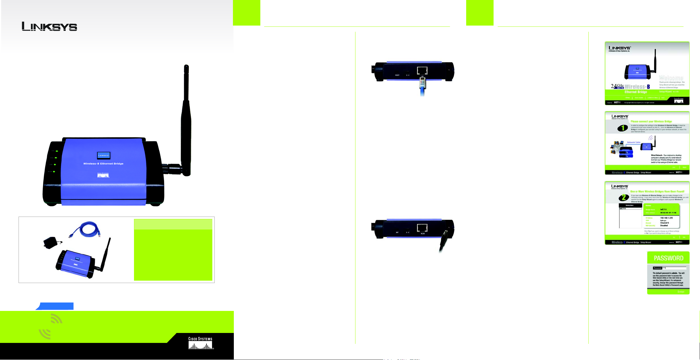
A Attach the Bridge’s antenna.
B Plug the included Ethernet
C The X-II (MDI/MDI-X) slide switch
D Plug the other end of the
E Plug the supplied power
Package Contents
• Wireless-B Ethernet Bridge
• Quick Installation Guide
• Setup CD-ROM
• User’s Guide on CD
• Detachable Antenna
• Power Adapter
•Network Cable
• Registration Card
Ethernet Bridge for Setup Ethernet Bridge
A Insert the Setup CD-ROM into
your PC’s CD-ROM drive. The
Setup Utility should run
network cable into the LAN port
on the back panel of the
Bridge.
offers a choice between two
settings. Slide the X-II switch to
the X position if you are
connecting the Bridge to a
PC’s network adapter. Slide the
X-II switch to the II position if
you are connecting the Bridge
to a hub or switch.
Ethernet network cable into the
RJ-45 port of the hub, switch,
or PC you wish to use to
configure the Bridge.
adapter into the Power port on
the back panel of the Bridge.
Then plug the other end into
an electrical outlet.
B
E
automatically, and the
Welcome screen should
appear. If it does not appear,
click the Start button and
choose Run. In the field that
appears, enter D:\setup.exe (if
“D” is the letter of your CD-ROM
drive).
B Click Setup to begin the setup
process.
C Make sure the Bridge is
correctly connected to your
wired network. Click Next.
D The screen displays a list of
Wireless-B Ethernet Bridges on
your network, along with their
status information. Select the
Bridge you are currently
installing by clicking its name in
the Selection box. Click Yes.
E The Password screen will
appear. In lowercase letters,
enter admin in the Password
field. Then click Enter.
A
C
D
Model No.
Model No.
802.11b
Wireless
WET11
E
Wireless-B
Ethernet Bridge
Quick Installation
Page 2
Connecting the Wireless-B
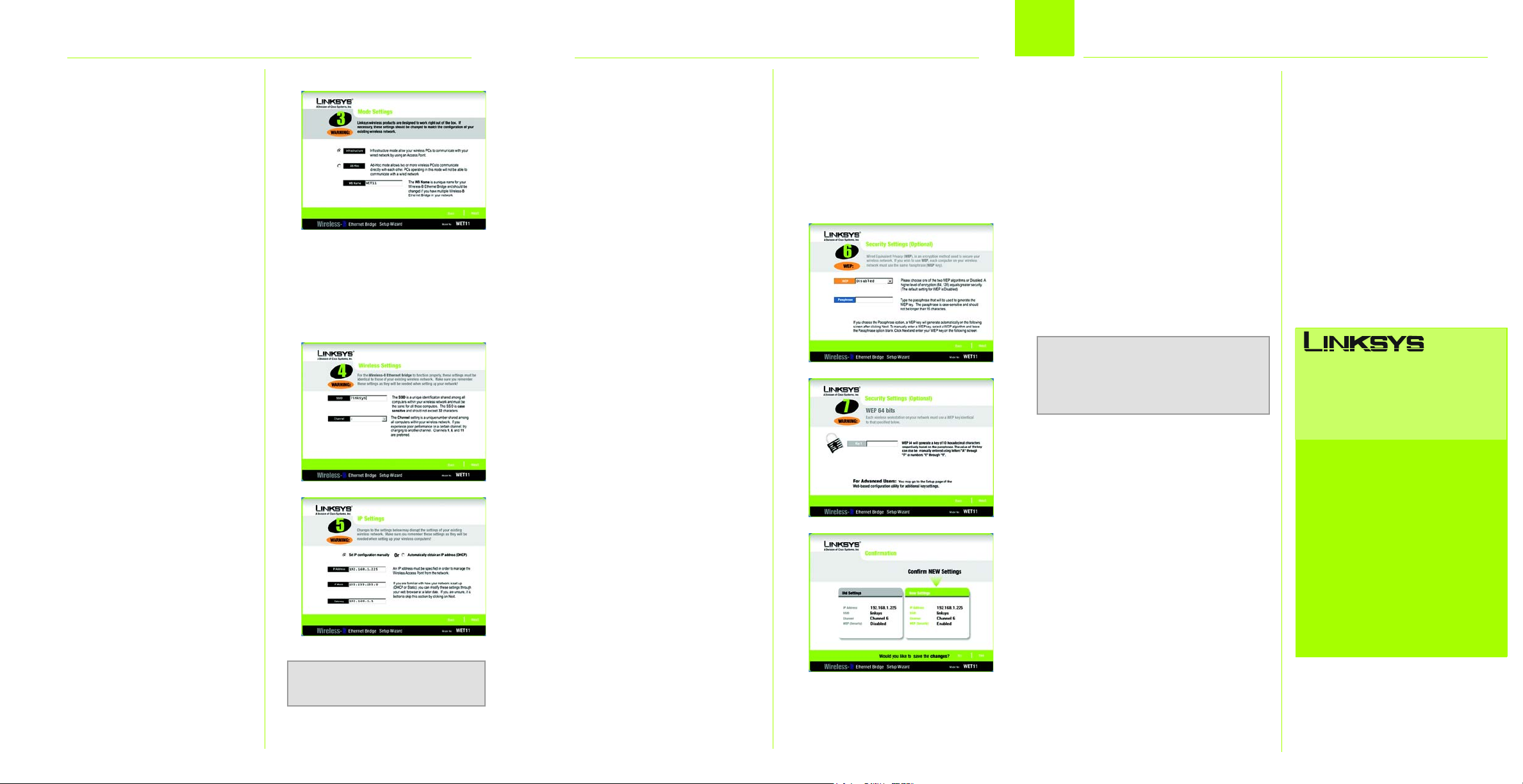
On the Mode Settings screen,
F
click the Infrastructure radio
button if you want your wireless
and wired networks to
communicate using a wireless
access point. Click the Ad-Hoc
radio button if you want
wireless computers to
communicate directly with
each other.
In the WB Name field, enter a
unique name for the Bridge.
Click Next.
G On the Wireless Settings
screen, enter your wireless
network’s SSID. If you chose AdHoc mode, select the channel
at which the network
broadcasts its wireless signal.
Then click Next.
H The IP Settings screen will
appear. If your network has a
router or DHCP server that
automatically assigns IP
addresses, click the radio
button next to Automatically
obtain an IP address (DHCP).
Click Next and proceed to
step I.
If you need to assign a static IP
address to the Bridge, click the
radio button next to Set IP
configuration manually. Enter
an IP Address, IP Mask (also
known as Subnet Mask), and
Model No.
F
G
H
NOTE: The default IP address of
the Bridge is 192.168.1.225.
Gateway appropriate for your
network. You must specify an IP
address on this screen. If you
are unsure about the IP Mask
and Gateway, leave these two
fields blank. Click Next and
proceed to step I.
I The Security Settings screen will
appear. If your network has
WEP encryption enabled, then
select the level of WEP
encryption, and enter a
Passphrase. If you do not have
a Passphrase and want to
manually enter a WEP key,
leave the Passphrase field
blank. If your network has WEP
encryption disabled, keep the
default, Disabled.
Then click Next.
J If you entered a Passphrase,
you will see the automatically
generated WEP key. (See Figure
J.) Otherwise, manually enter
the WEP key in the Key 1 field.
Click Next.
K Review your settings on the
Confirmation screen. Write
down the Bridge’s IP Address if
you want to access the
Bridge’s Web-based Utility. Click
Yes to save these settings.
L On the Congratulations
screen, click Exit.
K
J
3
Ethernet Bridge for Network Use
A After configuration, unplug the
power adapter from the
electrical outlet, and unplug
the Ethernet network cable
from the PC.
B Plug the Ethernet network
cable into the RJ-45 port on
the Ethernet-ready network
device you wish to add to the
wireless network.
C Plug the power adapter into a
local electrical outlet.
®
I
NOTE: If you do not have an active con-
nection to the Ethernet-ready network
device, then change the position of the
X-II switch.
Congratulations! The installation of
the Wireless-B Ethernet Bridge is
complete.
A Division of Cisco Systems, Inc.
For additional information or troubleshooting
help, refer to the User Guide on the Setup CDROM. You can also call or e-mail for further
support.
24-hour Technical Support
800-326-7114
(toll-free from US or Canada)
E-mail Support
support@linksys.com
Website
http://www.linksys.com or
http://support.linksys.com
RMA (Return Merchandise Authorization)
http://www.linksys.com/support
FTP Site
ftp://ftp.linksys.com
Sales Information
800-546-5797 (800-LINKSYS)
Linksys is a registered trademark or tradem ark of
Cisco Systems, Inc. and/or its affiliates in the U .S.
and certain other countries. Copyright © 2003
Cisco Systems, Inc. All rights reserved.
WET11_V2-QI-30919NC JL
 Loading...