

Page 1
USER GUIDE
Wireless-G ADSL2+ Gateway
Model: WAG54G2
Page 2
About This Guide
Icon Descriptions
While reading through the User Guide you may see
various icons that call attention to specific items. Below is
a description of these icons:
NOTE: This check mark indicates that there is
a note of interest and is something that you
should pay special attention to while using the
product.
WARNING: This exclamation point indicates
that there is a caution or warning and it is
something that could damage your property or
product.
About This Guide
WEB: This globe icon indicates a noteworthy
website address or e-mail address.
Online Resources
Website addresses in this document are listed without
http:// in front of the address because most current web
browsers do not require it. If you use an older web browser,
you may have to add http:// in front of the web address.
Resource Website
Linksys www.linksys.com
Linksys International www.linksys.com/international
Glossary www.linksys.com/glossary
Network Security www.linksys.com/security
Copyright and Trademarks
Linksys is a registered trademark
or trademark of Cisco Systems, Inc.
and/or its affiliates in the U.S. and
certain other countries. Copyright
© 2008 Cisco Systems, Inc. All rights
reserved. Other brands and product
names are trademarks or registered
trademarks of their respective
holders.
Wireless-G ADSL2+ Gateway
i
Page 3

Table of Contents
Chapter 1: Product Overview 1
Front Panel..................................................1
Back Panel . . . . . . . . . . . . . . . . . . . . . . . . . . . . . . . . . . . . . . . . . . . . . . . . . . 1
Placement Positions............................................ 1
Chapter 2: Wireless Security Checklist 3
General Network Security Guidelines .................................3
Additional Security Tips . . . . . . . . . . . . . . . . . . . . . . . . . . . . . . . . . . . . . . . . . 3
Chapter 3: Installation 4
Connection . . . . . . . . . . . . . . . . . . . . . . . . . . . . . . . . . . . . . . . . . . . . . . . . . 4
Setup . . . . . . . . . . . . . . . . . . . . . . . . . . . . . . . . . . . . . . . . . . . . . . . . . . . . . 4
Chapter 4: Advanced Conguration 5
Setup > Basic Setup . . . . . . . . . . . . . . . . . . . . . . . . . . . . . . . . . . . . . . . . . . . . 5
Setup > DDNS................................................10
Setup > MAC Address Clone.......................................10
Setup > Advanced Routing . . . . . . . . . . . . . . . . . . . . . . . . . . . . . . . . . . . . . . .11
Wireless > Basic Wireless Settings . . . . . . . . . . . . . . . . . . . . . . . . . . . . . . . . . . .11
Wireless > Wireless Security . . . . . . . . . . . . . . . . . . . . . . . . . . . . . . . . . . . . . . .12
Wireless > Wireless MAC Filter......................................15
Wireless > Advanced Wireless Settings . . . . . . . . . . . . . . . . . . . . . . . . . . . . . . . .15
Security > Firewall . . . . . . . . . . . . . . . . . . . . . . . . . . . . . . . . . . . . . . . . . . . . .16
Security > VPN Passthrough.......................................17
Access Restrictions > Internet Access Policy.............................17
Applications and Gaming > Single Port Forwarding........................18
Applications and Gaming > Port Range Forwarding . . . . . . . . . . . . . . . . . . . . . . .19
Applications & Gaming > Port Range Triggering . . . . . . . . . . . . . . . . . . . . . . . . . .19
Applications and Gaming > DMZ . . . . . . . . . . . . . . . . . . . . . . . . . . . . . . . . . . .20
Applications and Gaming > QoS . . . . . . . . . . . . . . . . . . . . . . . . . . . . . . . . . . . .20
Administration > Management.....................................22
Administration > Reporting . . . . . . . . . . . . . . . . . . . . . . . . . . . . . . . . . . . . . . .23
Administration > Diagnostics . . . . . . . . . . . . . . . . . . . . . . . . . . . . . . . . . . . . . .24
Administration > Back Up & Restore..................................24
Administration > Factory Defaults ...................................24
Administration > Firmware Upgrade . . . . . . . . . . . . . . . . . . . . . . . . . . . . . . . . .25
Administration > Language . . . . . . . . . . . . . . . . . . . . . . . . . . . . . . . . . . . . . . .25
Status > Gateway..............................................25
Status > Local Network . . . . . . . . . . . . . . . . . . . . . . . . . . . . . . . . . . . . . . . . . .26
Status > Wireless Network . . . . . . . . . . . . . . . . . . . . . . . . . . . . . . . . . . . . . . . .26
Status > DSL Connection.........................................27
Wireless-N ADSL2+ Gateway
Appendix A: Troubleshooting 28
Appendix B: Specications 29
ii
Page 4

Table of Contents
Appendix C: Warranty Information 30
Limited Warranty..............................................30
Appendix D: Regulatory Information 32
United States of America.........................................32
Canada . . . . . . . . . . . . . . . . . . . . . . . . . . . . . . . . . . . . . . . . . . . . . . . . . . . .33
Wireless Disclaimer . . . . . . . . . . . . . . . . . . . . . . . . . . . . . . . . . . . . . . . . . . . .34
Avis de non-responsabilité concernant les appareils sans l . . . . . . . . . . . . . . . . . .34
New Zealand . . . . . . . . . . . . . . . . . . . . . . . . . . . . . . . . . . . . . . . . . . . . . . . .34
European Union . . . . . . . . . . . . . . . . . . . . . . . . . . . . . . . . . . . . . . . . . . . . . .34
Wireless-N ADSL2+ Gateway
iii
Page 5
Chapter 1
Product Overview
Chapter 1:
Product Overview
Thank you for choosing the Linksys Wireless-G ADSL2+
Gateway. The Gateway lets you access the Internet via a
wireless connection or through one of its four switched
ports. You can also use the Gateway to share resources
such as computers, printers and files. A variety of security
features help to protect your data and your privacy while
online. Security features include WPA2 security, a Stateful
Packet Inspection (SPI) firewall and NAT technology.
Configuring the Gateway is easy using the provided
browser-based utility.
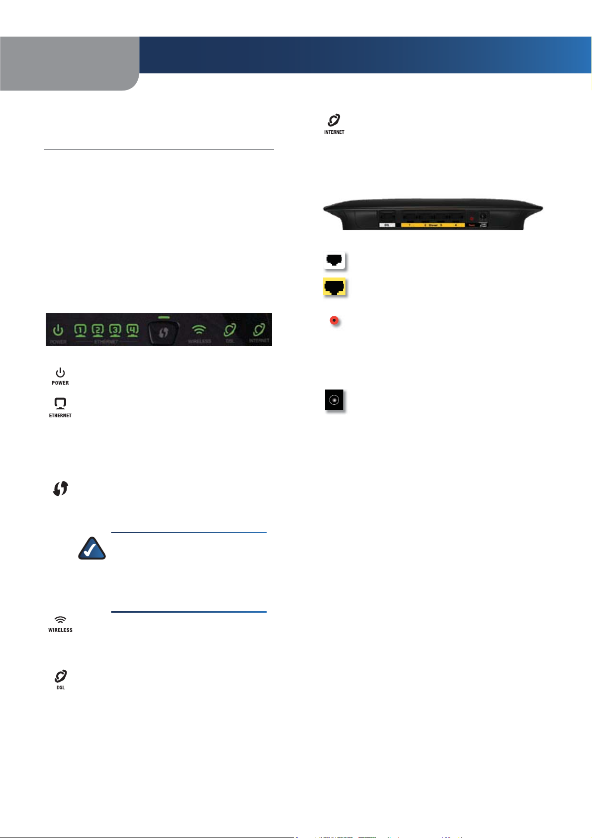
Front Panel
Power (Green) The Power LED lights up and
stays on while the Gateway is powered on.
Ethernet 1-4 (Green) These numbered LEDs,
corresponding with the numbered ports on
the Gateway’s back panel, serve two purposes.
If the LED is continuously lit, the Gateway is
successfully connected to a device through that
port. It flashes to indicate network activity over
that port.
Wi-Fi Protected Setup Button Press this
button to allow Wi-Fi Protected Setup to search
for your Wi-Fi Protected Setup-supported
wireless device.
NOTE: Wi-Fi Protected Setup is a
feature that makes it easy to configure
your wireless network and its security
settings. For more information, refer to
“Wireless > Basic Wireless Settings“ in
the “Advanced Configuration” chapter.
Internet (Green) The Internet LED lights up
and stays on when there is a connection made
through the Internet port. It flashes to indicate
network activity over the Internet port.
Back Panel
DSL The DSL port connects to the ADSL line.
Ethernet 1, 2, 3, 4 These Ethernet ports (1, 2,
3, 4) connect the Gateway to wired computers
and other Ethernet network devices.
Reset There are two ways to reset the Gateway’s
factory defaults. Either press and hold the Reset
button for approximately five seconds, or restore
the defaults from the Administration > Factory
Defaults screen of the Gateway’s web-based
utility.
Power The Power port is where you will
connect the power adapter.
Placement Positions
There are two ways to physically install the device. The
first way is to place the device horizontally on a surface.
The second way is to mount the device on a wall.
Horizontal Placement
The device has four rubber feet on its bottom panel. Place
the device on a level surface near an electrical outlet.
Wireless (Green) The Wireless LED lights up
when the wireless feature is enabled. It flashes
when the Gateway is actively sending or
receiving data over the network.
DSL (Green) The DSL LED lights up whenever
there is a successful DSL connection. The LED
flashes while the Gateway is establishing the
ADSL connection.
Wireless-G ADSL2+ Gateway
1
Page 6
Chapter 1
Product Overview
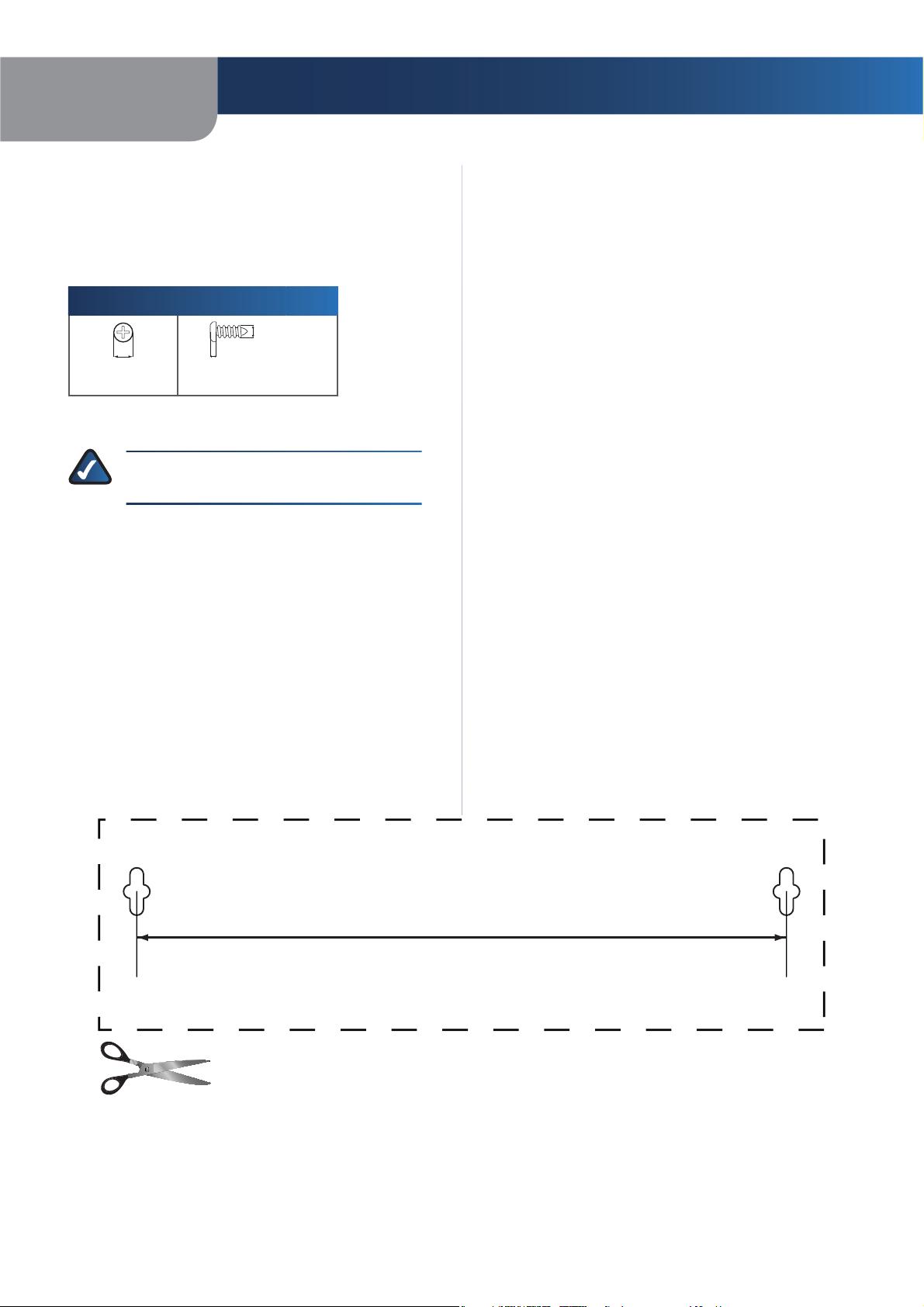
Wall-Mounting Placement
The Router has two wall-mount slots on its bottom
panel. The distance between the slots is 152 mm
(6 inches).
Two screws are needed to mount the Router.
Suggested Mounting Hardware
4-5 mm 1-1.5 mm
Note: Mounting hardware illustrations are not †
true to scale.
NOTE: Linksys is not responsible for damages
incurred by insecure wall-mounting hardware.
2.5-3.0 mm
Follow these instructions:
Determine where you want to mount the Router. Make 1.
sure that the wall you use is smooth, flat, dry, and
sturdy. Also make sure the location is within reach of
an electrical outlet.
Drill two holes into the wall. Make sure the holes are 2.
152 mm (6 inches) apart.
Insert a screw into each hole and leave 3 mm 3.
(0.12 inches) of its head exposed.
Maneuver the Router so the wall-mount slots line up 4.
with the two screws.
Place the wall-mount slots over the screws and slide 5.
the Router down until the screws fit snugly into the
wall-mount slots.
Wireless-G ADSL2+ Gateway
152 mm
Wall Mounting Template
2
Page 7
Chapter 2
Wireless Security Checklist
Chapter 2:
Wireless Security Checklist
Wireless networks are convenient and easy to install, so
homes with high-speed Internet access are adopting them
at a rapid pace. Because wireless networking operates by
sending information over radio waves, it can be more
vulnerable to intruders than a traditional wired network.
Like signals from your cellular or cordless phones, signals
from your wireless network can also be intercepted. Since
you cannot physically prevent someone from connecting
to your wireless network, you need to take some additional
steps to keep your network secure.
1. Change the default wireless
network name or SSID
Wireless devices have a default wireless network name
or Service Set Identifier (SSID) set by the factory. This
is the name of your wireless network, and can be up
to 32 characters in length. Linksys wireless products
use linksys as the default wireless network name. You
should change the wireless network name to something
unique to distinguish your wireless network from other
wireless networks that may exist around you, but do not
use personal information (such as your Social Security
number) because this information may be available for
anyone to see when browsing for wireless networks.
2. Change the default password
For wireless products such as access points, routers, and
gateways, you will be asked for a password when you
want to change their settings. These devices have a default
password set by the factory. The Linksys default password
is admin. Hackers know these defaults and may try to
use them to access your wireless device and change your
network settings. To thwart any unauthorized changes,
customize the device’s password so it will be hard to
guess.
4. Enable encryption
Encryption protects data transmitted over a wireless
network. Wi-Fi Protected Access (WPA/WPA2) and Wired
Equivalency Privacy (WEP) offer different levels of security
for wireless communication.
A network encrypted with WPA/WPA2 is more secure
than a network encrypted with WEP, because WPA/WPA2
uses dynamic key encryption. To protect the information
as it passes over the airwaves, you should enable the
highest level of encryption supported by your network
equipment.
WEP is an older encryption standard and may be the
only option available on some older devices that do not
support WPA.
General Network Security Guidelines
Wireless network security is useless if the underlying
network is not secure.
s
Password protect all computers on the network and
individually password protect sensitive files.
s
Change passwords on a regular basis.
Install anti-virus software and personal firewall s
software.
s
Disable file sharing (peer-to-peer). Some applications
may open file sharing without your consent and/or
knowledge.
Additional Security Tips
Keep wireless routers, access points, or gateways away s
from exterior walls and windows.
s
Turn wireless routers, access points, or gateways
off when they are not being used (at night, during
vacations).
s
Use strong passphrases that are at least eight characters
in length. Combine letters and numbers to avoid using
standard words that can be found in the dictionary.
3. Enable MAC address filtering
Linksys routers and gateways give you the ability to
enable Media Access Control (MAC) address filtering. The
MAC address is a unique series of numbers and letters
assigned to every networking device. With MAC address
filtering enabled, wireless network access is provided
solely for wireless devices with specific MAC addresses.
For example, you can specify the MAC address of each
computer in your home so that only those computers can
access your wireless network.
Wireless-G ADSL2+ Gateway
WEB: For more information on wireless
security, visit www.linksys.com/security
3
Page 8
Chapter 3
Installation
Chapter 3:
Installation
Linksys strongly recommends that you run the Setup CDROM. If you have problems running the Setup CD-ROM,
use this chapter.
Connection
Make sure that all the devices that you are working 1.
with are powered down, including your computer(s)
and the Gateway. If you have a modem connected
to your network, disconnect it. The Gateway replaces
your modem.
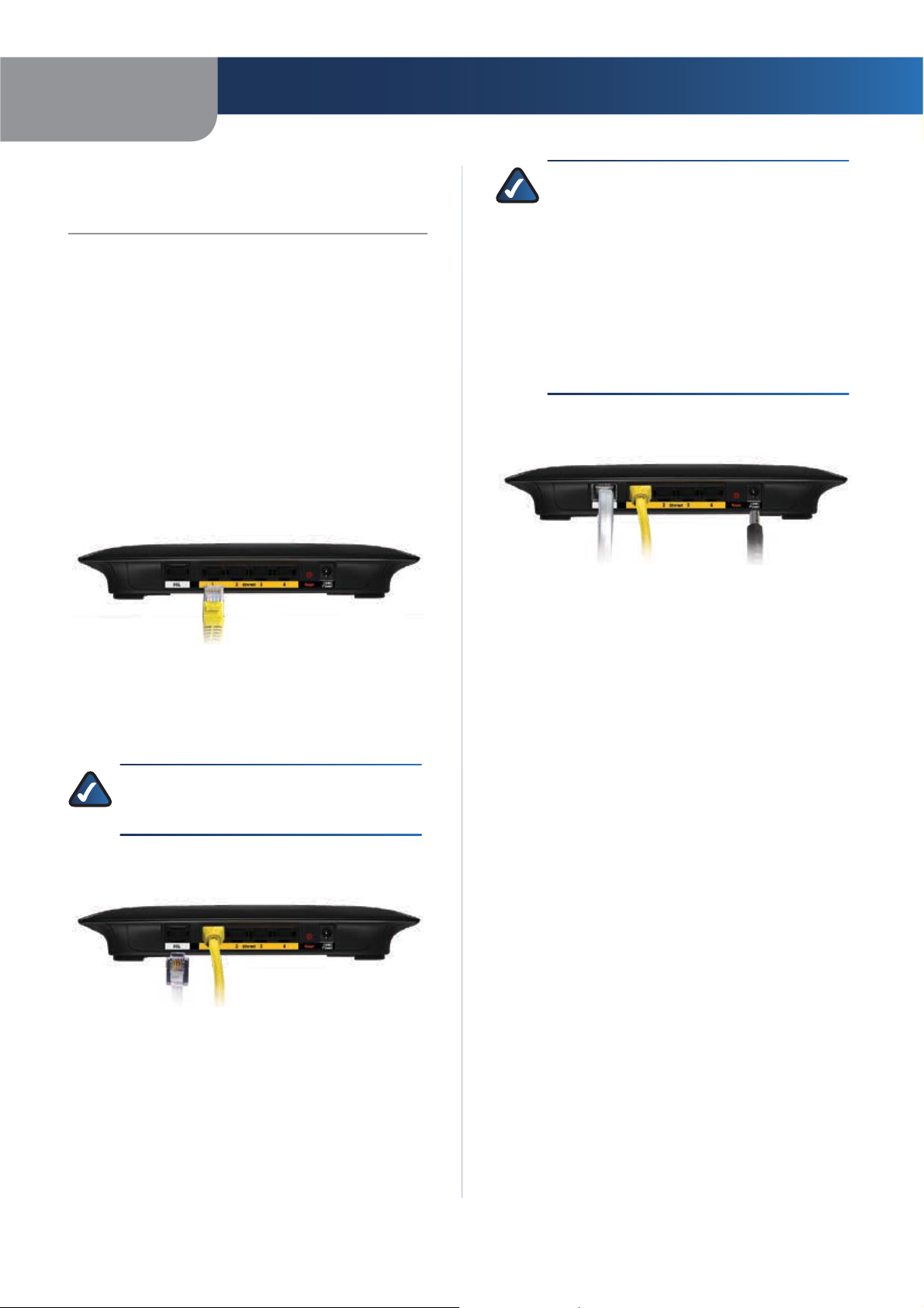
Connect one end of the provided Ethernet cable to 2.
your computer’s Ethernet adapter. Connect the other
end of the Ethernet cable to one of the Ethernet ports
on the back of the Gateway.
Connect the Computer
Repeat step 2 for every computer or device that you 3.
want to connect to the Gateway via Ethernet. If you
connect more than four computers to the Gateway,
you also need to connect a switch to the Gateway.
NOTE: If your computer’s Ethernet adapter
is not set up, refer to the Ethernet adapter’s
documentation for more information.
Connect one end of the phone cable to the DSL port 4.
on the back of the Gateway.
NOTE: To avoid interference, you may need to
place a microfilter or splitter between the phone
cable and wall jack. Contact your ISP to determine
if one is required. (UK residents need to connect
the microfilter to the wall phone jack with ADSL
service and then connect one end of the provided
phone cable to the DSL port on it.) If you have
more than one phone and you experience static
on the line after installing the Gateway, then you
need to install an additional microfilter for each
phone or fax that you use. If you use ISDN, then
you do not need a microfilter.
Connect the power adapter to the Gateway’s power 6.
port and the electrical outlet.
Connect the Power
Power on the computer that you want to use to 7.
configure the Gateway.
The Power, Wireless, and at least one of the numbered 8.
Ethernet (1, 2, 3, or 4) LEDs should light up. If not, make
sure the Gateway is powered on and the cables are
securely connected.
Connection is complete.
Continue to the “Setup” section.
Setup
For setup, configure the Gateway to access the Internet
through your ADSL Internet Service Provider (ISP). Use the
setup information provided by your ISP.
Continue to “Chapter 4: Advanced Configuration”, and
complete the following sections:
Connect the DSL
Connect the other end of the phone cable to the wall 5.
jack with ADSL service or microfilter.
Wireless-G ADSL2+ Gateway
s
Setup > Basic Setup
Wireless > Basic Wireless Settingss
Wireless > Wireless Securitys
After completing the setup, to test it, enter
www.linksys.com/uk/registration in the web browser’s
Address field, and press Enter.
Installation is complete.
4
Page 9
Chapter 4
Advanced Configuration
Chapter 4:
Advanced Configuration
After setting up the Gateway with the Setup Wizard
(located on the CD-ROM), the Gateway will be ready
for use. However, if you’d like to change its advanced
settings, use the Gateway’s web-based utility. This chapter
describes each web page of the utility and each page’s key
functions. You can access the utility via a web browser on
a computer connected to the Gateway.
The web-based utility has these main tabs: Setup,
Wireless, Security, Access Restrictions, Applications &
Gaming, Administration, and Status. Additional tabs will
be available after you click one of the main tabs.
NOTE: When first installing the Gateway, you
should use the Setup Wizard on the Setup CDROM. If you want to configure advanced settings,
use this chapter.
NOTE: For New Zealand residents, refer to the
note under RFC 2364 PPPoA.
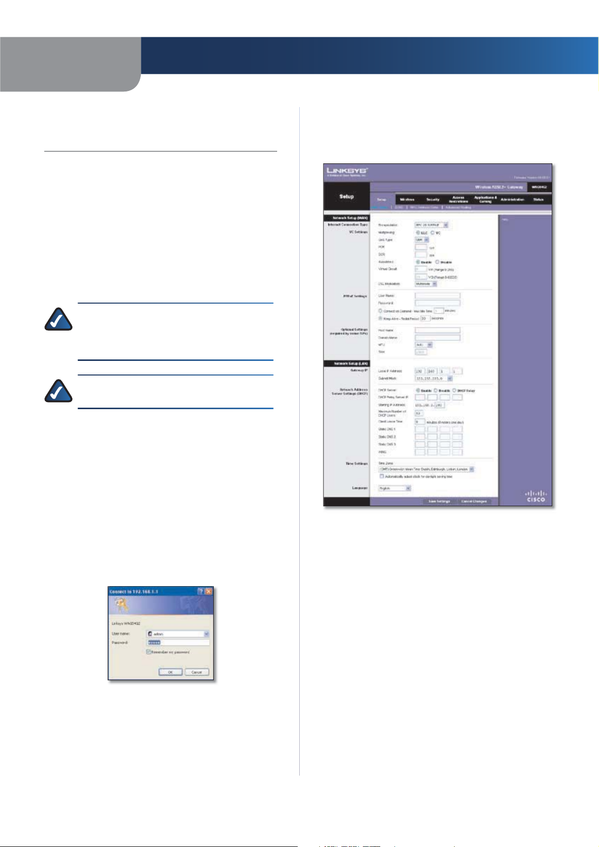
Setup > Basic Setup
The first screen that appears is the Basic Setup screen. This
allows you to change the Gateway’s general settings.
How to Access the Web-Based Utility
To access the web-based utility, launch the web browser
on your computer, and enter the Gateway’s default IP
address, 192.168.1.1, in the Address field. Then, press
Enter.
A login screen appears. Use the default user name and
password, admin, unless you have changed them during
the Setup Wizard. (You can set a new user name and
password from the Administration tab’s Management
screen.) Click OK to continue.
Gateway Login
If you are unable to log in, press the Reset button on the
back panel for at least 5 seconds, then wait for the device
to reset and try again.
Setup > Basic Setup
Internet Setup
The Internet Setup section configures the Gateway to
your Internet connection. Most of this information can be
obtained through your ISP.
Internet Connection Type
Encapsulation Select the appropriate encapsulation
method from the drop-down menu. Each Basic Setup
screen and available features will differ depending on
which encapsulation method you select. These are the
available methods:
s
RFC 2364 PPPoA
RFC 2516 PPPoEs
RFC 1483 Routeds
IPoAs
RFC 1483 Bridgeds
Bridged Mode Onlys
Wireless-G ADSL2+ Gateway
5
Page 10
Chapter 4
Advanced Configuration
VC Settings
Configure your Virtual Circuit (VC) settings in this section.
Multiplexing Select LLC or VC, depending on your ISP.
QoS Type Select from the drop-down menu: CBR
(Continuous Bit Rate) to specify fixed bandwidth for voice
or data traffic; UBR (Unspecified Bit Rate) for applications
that are not time-sensitive, such as e-mail; or VBR (Variable
Bit Rate) for bursty traffic and bandwidth-sharing with
other applications.
PCR For the Peak Cell Rate (PCR), divide the DSL line rate
by 424 to get the maximum rate the sender can send
cells. Enter the rate in the field (if required by your service
provider).
SCR The Sustain Cell Rate (SCR) sets the average cell rate
that can be transmitted. The SCR value is normally less
than the PCR value. Enter the rate in the field (if required
by your service provider).
Autodetect Select Enable to have the VPI/VCI settings
automatically detected, or select Disable to enter the
values manually.
Virtual Circuit These fields consist of two items: VPI
(Virtual Path Identifier) and VCI (Virtual Channel Identifier).
Enter the settings provided by your ISP.
DSL Modulation Select the appropriate mode:
MultiMode, T1.413, G.dmt, G.lite, ADSL2, ADSL2+,
ADSL2 L, ADSL2 M, or ADSL2+ M. Contact your ISP if you
are not sure which mode to use.
Follow the instructions for your type of encapsulation.
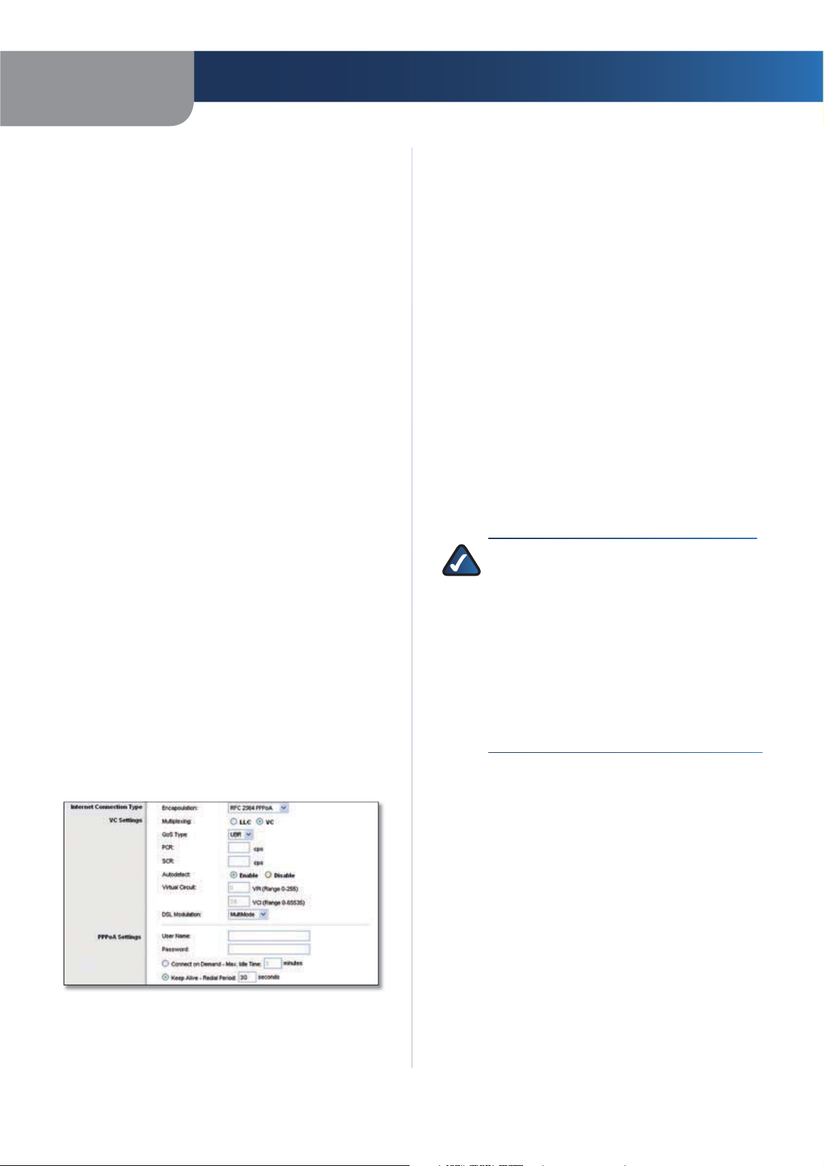
RFC 2364 PPPoA
Some DSL-based ISPs use PPPoA (Point-to-Point Protocol
over ATM) to establish Internet connections. If you are
connected to the Internet through a DSL line, check with
your ISP to see if they use PPPoA. If they do, you will have
to enable PPPoA.
PPPoA Settings
User Name and Password Enter the User Name and
Password provided by your ISP.
Connect on Demand - Max Idle Time You can configure
the Gateway to cut the Internet connection after it has
been inactive for a specified period of time (Max Idle Time).
If your Internet connection has been terminated due to
inactivity, Connect on Demand enables the Gateway to
automatically re-establish your connection as soon as you
attempt to access the Internet again. To use this option,
select Connect on Demand. In the Max Idle Time field,
enter the number of minutes you want to have elapsed
before your Internet connection terminates. The default
Max Idle Time is 5 minutes.
Keep Alive - Redial Period If you select this option,
the Gateway will periodically check your Internet
connection. If you are disconnected, then the Gateway
will automatically re-establish your connection. To
use this option, select Keep Alive. In the Redial Period
field, specify how often you want the Gateway to check
the Internet connection. The default Redial Period is
30 seconds.
NOTE: For New Zealand, follow these
instructions:
Select 1. RFC 2364 PPPoA from the
Encapsulation drop-down menu.
For the Virtual Circuit ID, enter 2. 0 for the VPI
and 100 for the VCI.
Select 3. VC for Multiplexing.
Select 4. Multimode from the DSL Modulation
drop-down menu.
Obtain the User Name and Password details 5.
from your ISP.
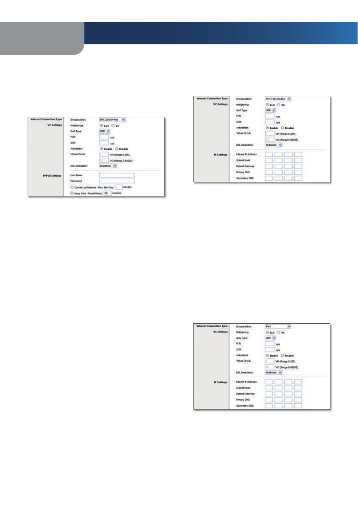
Internet Connection Type > RFC 2364 PPPoA
Wireless-G ADSL2+ Gateway
6
Page 11
Chapter 4
Advanced Configuration
RFC 2516 PPPoE
Some DSL-based ISPs use PPPoE (Point-to-Point Protocol
over Ethernet) to establish Internet connections. If you are
connected to the Internet through a DSL line, check with
your ISP to see if they use PPPoE. If they do, you will have
to enable PPPoE.
Internet Connection Type > RFC 2516 PPPoE
PPPoE Settings
User Name and Password Enter the User Name and
Password provided by your ISP.
Connect on Demand - Max Idle Time You can configure
the Gateway to cut the Internet connection after it has
been inactive for a specified period of time (Max Idle Time).
If your Internet connection has been terminated due to
inactivity, Connect on Demand enables the Gateway to
automatically re-establish your connection as soon as you
attempt to access the Internet again. To use this option,
select Connect on Demand. In the Max Idle Time field,
enter the number of minutes you want to have elapsed
before your Internet connection terminates. The default
Max Idle Time is 5 minutes.
Keep Alive - Redial Period If you select this option,
the Gateway will periodically check your Internet
connection. If you are disconnected, then the Gateway
will automatically re-establish your connection. To use
this option, select Keep Alive. In the Redial Period field,
you specify how often you want the Gateway to check
the Internet connection. The default Redial Period is
30 seconds.
RFC 1483 Routed
If you are required to use RFC 1483 Routed, then select
RFC 1483 Routed.
Internet Connection Type > RFC 1483 Routed
IP Settings
Your ISP provides these settings.
Internet IP Address Enter the Gateway’s IP address, as
seen from the Internet.
Subnet Mask Enter the Gateway’s Subnet Mask, as seen
from the Internet (including your ISP).
Default Gateway Enter the IP address of the ISP server.
Primary (Required) and Secondary (Optional)
Enter the DNS (Domain Name System) server IP
DNS
address(es) provided by your ISP. At least one is required.
IPoA
If you are required to use IPoA (IP over ATM), then select
IPoA.
Wireless-G ADSL2+ Gateway
Internet Connection Type > IPoA
7
Page 12
Chapter 4
Advanced Configuration
IP Settings
Your ISP provides these settings.
Internet IP Address Enter the Gateway’s IP address, as
seen from the Internet.
Subnet Mask Enter the Gateway’s Subnet Mask, as seen
from the Internet (including your ISP).
Default Gateway Enter the IP address of the ISP server.
Primary (Required) and Secondary (Optional)
Enter the DNS (Domain Name System) server IP
DNS
address(es) provided by your ISP. At least one is required.
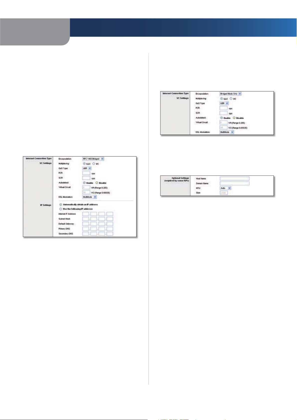
RFC 1483 Bridged
If you are required to use RFC 1483 Bridged, then select
RFC 1483 Bridged.
Bridged Mode Only
If you are using your Gateway as a bridge, which makes
the Gateway act like a stand-alone modem, select Bridge
Mode Only. All NAT and routing settings are disabled in
this mode.
Internet Connection Type > Bridged Mode Only
Optional Settings
Some of these settings may be required by your ISP. Verify
with your ISP before making any changes.
Internet Connection Type > RFC 1483 Bridged
IP Settings
Select Automatically obtain an IP address if your ISP
says you are connecting through a dynamic IP address.
If you are required to use a permanent (static) IP address
to connect to the Internet, then select Use the following
IP Address. Your ISP provides the settings needed for the
following fields:
Internet IP Address Enter the Gateway’s IP address, as
seen from the Internet.
Subnet Mask Enter the Gateway’s Subnet Mask, as seen
from the Internet (including your ISP).
Default Gateway Enter the IP address of the ISP server.
Primary (Required) and Secondary (Optional)
Enter the DNS (Domain Name System) server IP
DNS
address(es) provided by your ISP. At least one is required.
Optional Settings
Host Name and Domain Name These fields allow you
to supply a host and domain name for the Gateway.
Some ISPs, usually cable ISPs, require these names as
identification. You may have to check with your ISP to see
if your broadband Internet service has been configured
with a host and domain name. In most cases, leaving these
fields blank will work.
MTU MTU is the Maximum Transmission Unit. It specifies
the largest packet size permitted for Internet transmission.
Select Manual if you want to manually enter the largest
packet size that is transmitted. To have the Gateway select
the best MTU for your Internet connection, keep the
default, Auto.
Size When Manual is selected in the MTU field, this option
is enabled. Leave this value in the 1200 to 1500 range. The
default, MTU is configured automatically.
Wireless-G ADSL2+ Gateway
8
Page 13
Chapter 4
Advanced Configuration
Network Setup
The Network Setup section changes the settings on the
network connected to the Gateway’s Ethernet ports.
Wireless setup is performed through the Wireless tab.
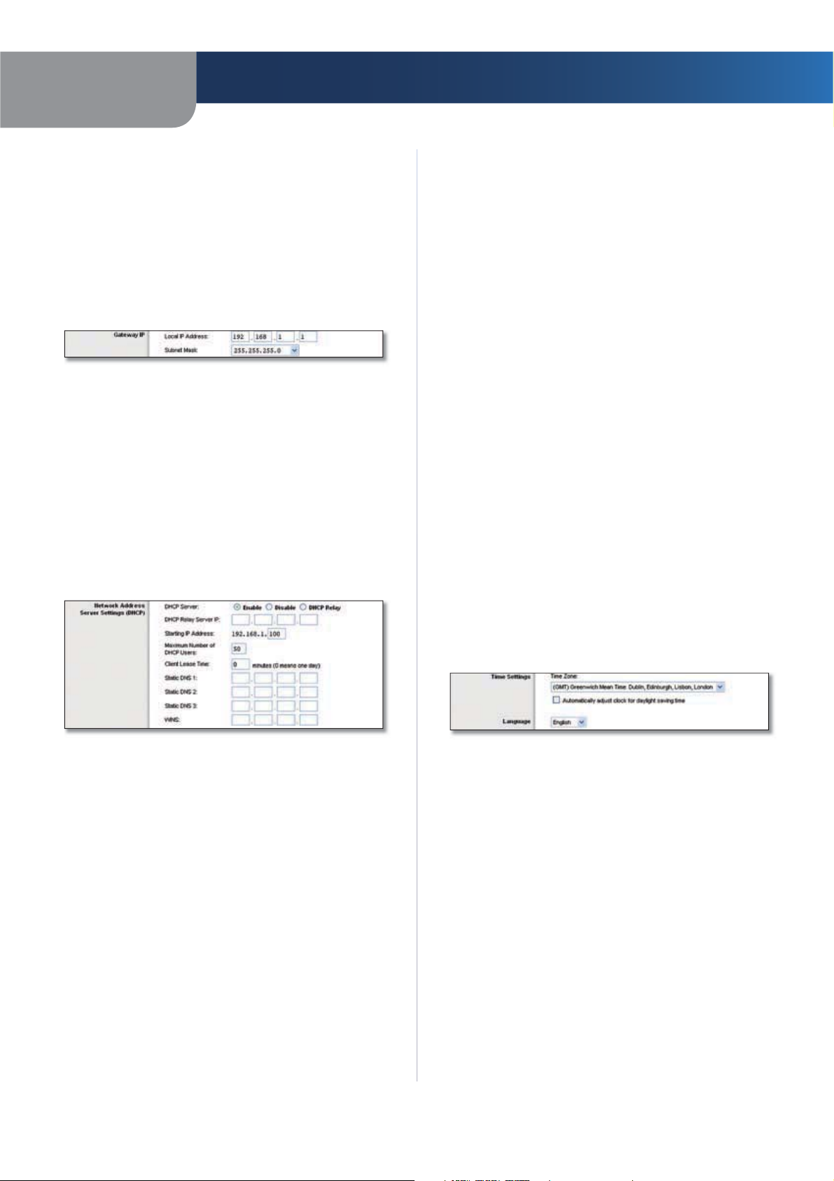
Gateway IP
The values for the Gateway’s Local IP Address and Subnet
Mask are shown here. In most cases, keeping the default
values will work.
Gateway IP
Local IP Address The default value is 192.168.1.1.
Subnet Mask The default value is 255.255.255.0.
Network Address Server Settings (DHCP)
The settings allow you to configure the Gateway’s Dynamic
Host Configuration Protocol (DHCP) server function. The
Gateway can be used as a DHCP server for your network.
A DHCP server automatically assigns an IP address to each
computer on your network. If you choose to enable the
Gateway’s DHCP server option, make sure there is no
other DHCP server on your network.
Maximum Number of DHCP Users Enter the maximum
number of users (network devices) that can obtain an IP
address. The number will vary depending on the starting
IP address entered and cannot be greater than 253. The
default is 50.
Client Lease Time The Client Lease Time is the amount
of time a network device will be allowed connection to
the Gateway with its current dynamic IP address. Enter the
number of minutes that the device will be “leased” this
dynamic IP address. After the time is up, the device will
be automatically assigned a new dynamic IP address. The
default is 0 minutes, which means one day.
Static DNS 1-3 The Domain Name System (DNS) is how
the Internet translates domain or website names into
Internet addresses or URLs. At least one DNS server IP
address is provided by your ISP. You can enter up to three
DNS server IP addresses here. The Gateway will use these
for quicker access to functioning DNS servers.
WINS The Windows Internet Naming Service (WINS)
converts NetBIOS names to IP addresses. If you use a WINS
server, enter that server’s IP address here. Otherwise, leave
this field blank.
Time Settings
Time Zone Select the time zone in which your network
functions.
Automatically adjust clock for daylight saving
Select this option if you want the Gateway to
time
automatically adjust for daylight saving time.
Network Address Server Settings (DHCP)
DHCP Server A Dynamic Host Configuration Protocol
(DHCP) server automatically assigns an IP address to each
computer on your network for you. Unless you already
have one, Linksys recommends that you keep the default,
Enable. You can also use the Gateway in DHCP Relay
mode. (This setting is not available for all encapsulation
types.)
DHCP Relay Server IP Enter the DHCP server IP address
to relay DHCP requests from the local network when the
Gateway is in DHCP Relay mode.
Starting IP Address Enter a value for the DHCP server
to start with when issuing IP addresses. Because the
Gateway’s default IP address is 192.168.1.1, the Starting IP
Address must be 192.168.1.2 or greater, but smaller than
192.168.1.253. The default is 192.168.1.100.
Wireless-G ADSL2+ Gateway
Time Settings and Language
Language
Language
the drop-down menu. The language of the web-based
utility will change five seconds after you select another
language.
Click Save Settings to apply your changes, or click Cancel
Changes to cancel your changes.
To use a different language, select one from
9
Page 14
Chapter 4
Advanced Configuration
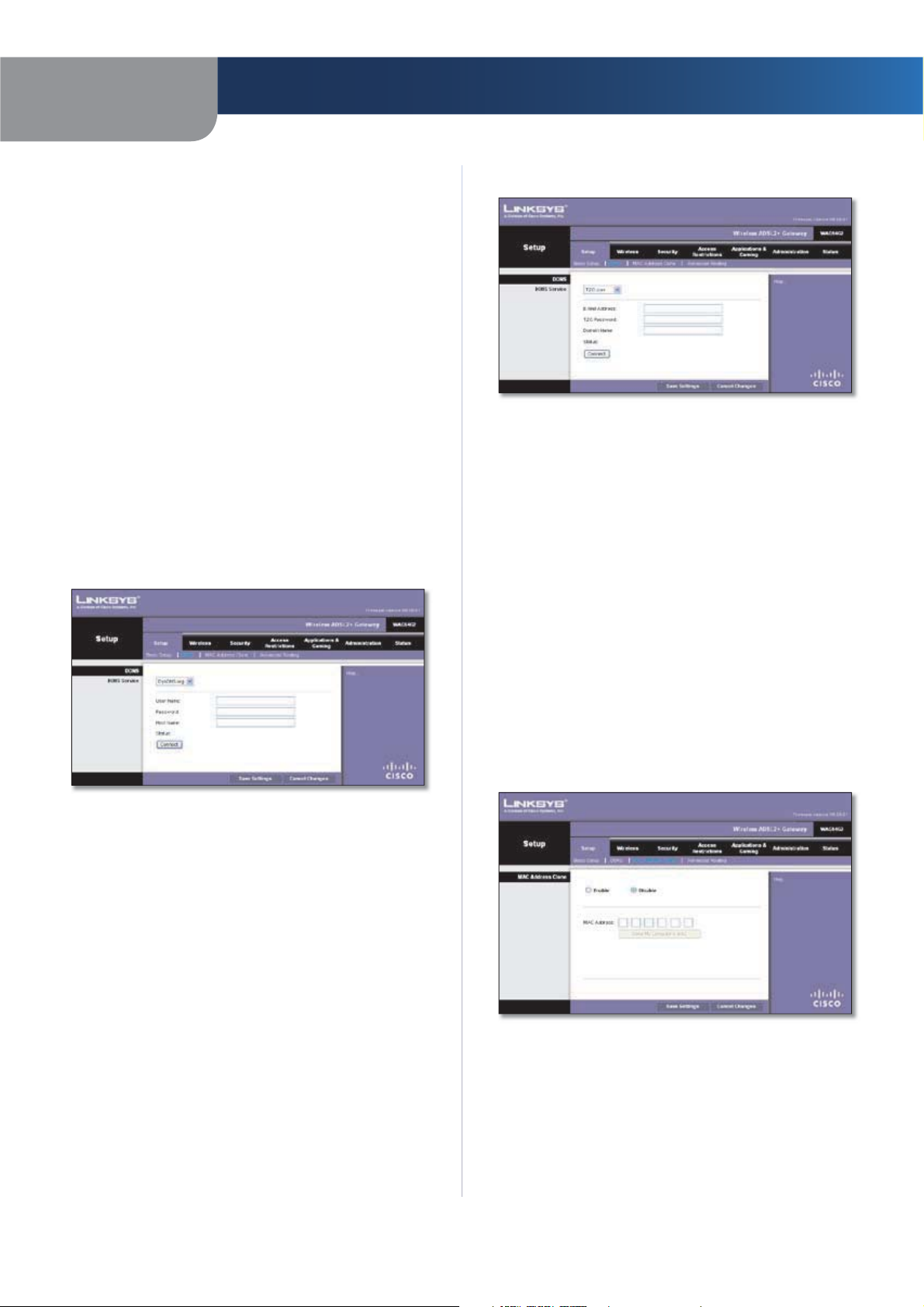
Setup > DDNS
The Gateway offers a Dynamic Domain Name System
(DDNS) feature. DDNS lets you assign a fixed host and
domain name to a dynamic Internet IP address. It is useful
when you are hosting your own website, FTP server, or
other server behind the Gateway.
Before you can use this feature, you need to sign
up for DDNS service with a DDNS service provider,
www.dyndns.org or www.TZO.com. If you do not want to
use this feature, keep the default, Disable.
DDNS
DDNS Service
If your DDNS service is provided by DynDNS.org, then
select DynDNS.org from the drop-down menu. If your
DDNS service is provided by TZO, then select TZO.com.
The features available on the DDNS screen will vary,
depending on which DDNS service provider you use.
DynDNS.org
TZO.com
Setup > DDNS > TZO
E-Mail Address
TZO Password Enter the Password for your account.
Domain Name
Status
Connect
Click Save Settings to apply your changes, or click Cancel
Changes to cancel your changes.
Displays the status of the DDNS service connection.
Enter the E-mail Address for your account.
Enter the DDNS URL assigned by the service
To manually trigger an update, click this button.
.
Setup > DDNS > DynDNS
User Name Enter the User Name for your account.
Password Enter the Password for your account.
Host Name Enter the DDNS URL assigned by the service.
Status
Connect
Click Save Settings to apply your changes, or click Cancel
Changes to cancel your changes.
Displays the status of the DDNS service connection.
To manually trigger an update, click this button.
Setup > MAC Address Clone
A MAC address is a 12-digit code assigned to a unique
piece of hardware for identification. Some ISPs will require
you to register a MAC address in order to access the
Internet. If you do not wish to re-register the MAC address
with your ISP, you may assign the MAC address you have
currently registered with your ISP to the Gateway with the
MAC Address Clone feature.
Setup > MAC Address Clone
Enable/Disable To have the MAC Address cloned, click
the radio button beside Enable.
MAC Address Enter the MAC Address registered with
your ISP here.
Clone My Computer’s MAC Clicking this button will
clone the MAC address.
Wireless-G ADSL2+ Gateway
10
Page 15

Chapter 4
Advanced Configuration
Click Save Settings to apply your changes, or click Cancel
Changes to cancel your changes.
Setup > Advanced Routing
The Advanced Routing screen is used to set up the
Gateway’s advanced routing functions. It contains three
sections: Operating Mode, Dynamic Routing, and Static
Routing.
Setup > Advanced Routing
Destination IP Address The Destination IP Address is
the IP address of the remote network or host to which
you want to assign a static route. Enter the IP address of
the host for which you wish to create a static route. If you
are building a route to an entire network, be sure that the
network portion of the IP address is set to 0.
Subnet Mask The Subnet Mask determines which
portion of a Destination IP Address is the network portion,
and which portion is the host portion.
Gateway The IP address of the gateway device that allows
contact between the Gateway and remote network or host.
Hop Count This is the number of hops to each node until
the destination is reached (16 hops maximum). Enter the
appropriate Hop Count.
Click Show Routing Table to view the static routes you
have already set up.
Routing Table
For each route, the Destination LAN IP address, Subnet
Mask, Gateway, and Interface are displayed. Click Refresh
to update the information. Click Close to exit this screen.
Advanced Routing
Operating Mode
NAT If this Gateway is hosting your network’s connection
to the Internet, keep the default, Enable. If another
gateway or router exists on your network, select Disable.
Dynamic Routing
RIP This allows the Gateway to automatically adjust to
physical changes in the network’s layout and exchange
routing tables with other router(s). The G ateway determines
the packets’ route based on the fewest number of hops
between source and destination. Select Enable to use
Dynamic Routing. Otherwise, keep the default, Disable.
RIP Send Packet Version, and RIP Received Packet
Version
or RIP v2. This should match the version supported by
other routers on your LAN.
Static Routing
A static route is a pre-determined pathway that network
information must travel to reach a specific host or network.
Enter the following information to set up a new static route.
Select Set Number To set up a static route between the
Gateway and another network, select a number from the
drop-down list. The Gateway supports up to 20 static route
entries. Click Delete This Entry to delete a static route.
Select the appropriate protocol version, RIP v1
Advanced Routing > Routing Table
Click Save Settings to apply your changes, or click Cancel
Changes to cancel your changes.
Wireless > Basic Wireless Settings
The basic settings for wireless networking are set on this
screen. This screen allows you to choose your wireless
network mode and wireless security.
Wireless > Basic Wireless Settings
Wireless-G ADSL2+ Gateway
11
Page 16

Chapter 4
Basic Wireless Settings
Wireless Configuration Keep the default selection,
Manual, to configure your wireless network manually.
Select Wi-Fi Protected Setup to set up your wireless
network using Wi-Fi Protected Setup.
Manual
If you set the Wireless Configuration to Manual, the Basic
Wireless Settings screen displays the following fields.
Network Mode Select the wireless standards running
on your network. If you have Wireless-G and Wireless-B
devices in your network, keep the default, Mixed. If you
do not have any wireless devices, select Disable.
Network Name (SSID) The network name is case-sensitive
and must not exceed 32 characters (use any of the characters
on the keyboard). Linksys recommends that you change the
default, linksys, to a unique name of your choice.
Wireless Channel Select the channel you want to use.
All devices in your wireless network must use the same
channel in order to communicate.
SSID Broadcast When wireless devices survey the local
area for wireless networks to associate with, they will
detect the wireless network name or SSID broadcast by
the Gateway. If you want to broadcast the Gateway’s SSID,
keep the default, Enable. Otherwise, select Disable.
Click Save Settings to apply your changes, or click Cancel
Changes to cancel your changes.
Advanced Configuration
s Enter
The device asks for the Gateway’s PIN number
the PIN number displayed on the screen.
Click Save Settings to apply your changes, or click Cancel
Changes to cancel your changes.
Wireless > Wireless Security
The Wireless Security screen configures the security of
your wireless network(s). The supported wireless security
modes are WPA2-Personal, WPA-Personal, WPA2-Mixed,
WPA2-Enterprise, WPA-Enterprise, RADIUS, and WEP. WPA
(Wi-Fi Protected Access), is a security standard stronger
than WEP (Wired Equivalent Privacy) encryption. WPA2
is a more advanced, more secure version of WPA. WPAEnterprise, WPA2-Enterprise, and RADIUS use a RADIUS
(Remote Authentication Dial-In User Service) server for
authentication. For detailed instructions on configuring
wireless security on the Gateway, refer to “Chapter 2:
Wireless Security”.
Wireless Security
Security Mode Select the security method for
your wireless network. Proceed to the appropriate
instructions.
NOTE: If you use wireless security, remember
that each device in your wireless network MUST
use the same security method and settings, or
else the wireless devices cannot communicate.
Wi-Fi Protected Setup
If you set the Wireless Configuration to Wi-Fi Protected
Setup, the Basic Wireless Settings screen displays the fields
shown below.
Wireless > Basic Wireless Settings - Wi-Fi Protected Setup
Configure your wireless network by adding your Wi-Fi
Protected Setup-supported devices one at a time, using
the appropriate method listed below:
The device has a Wi-Fi Protected Setup buttons Press
the Wi-Fi Protected Setup button, then click the Wi-Fi
Protected Setup button on the screen. Searching... is
displayed while the Gateway searches for your device.
The device has a Wi-Fi Protected Setup PIN
s
number Enter the PIN number in the field provided
on the screen.
WPA2-Personal
Security Mode > WPA2-Personal
Encryption The method is TKIP or AES.
Pre-Shared Key Enter a key of 8 to 63 characters.
Key Renewal Enter how often the Gateway should
change encryption keys. The default is 3600 seconds.
Wireless-G ADSL2+ Gateway
12
Page 17

Chapter 4
Advanced Configuration
WPA-Personal
Security Mode > WPA-Personal
Encryption The method is TKIP or AES.
Pre-Shared Key Enter a key of 8 to 63 characters.
Key Renewal Enter a Key Renewal period, which instructs
the Gateway how often it should change the encryption
keys. The default is 3600 seconds.
WPA2-Mixed
This option allows clients to use EITHER WPA-Personal OR
WPA2-Personal.
WPA2-Enterprise
WPA2-Enterprise features WPA2 used with a RADIUS
server. (This method should only be used when the device
is connected to a RADIUS server.)
Security Mode > WPA2-Enterprise
Encryption The method is TKIP or AES.
RADIUS Server Enter the IP address of the RADIUS server.
RADIUS Port Enter the port number of the RADIUS server.
Shared Key Enter the key shared between the device
and its RADIUS server.
Key Renewal Enter the Key Renewal period, which tells
the device how often it should change the dynamic
encryption keys.
Click Save Settings to apply your changes, or click Cancel
Changes to cancel your changes.
Security Mode > WPA2-Mixed
Encryption The method is TKIP or AES.
Pre-Shared Key Enter a key of 8 to 63 characters.
Key Renewal Enter a Key Renewal period, which instructs
the Gateway how often it should change the encryption
keys. The default is 3600 seconds.
WPA-Enterprise
WPA-Enterprise features WPA used with a RADIUS server.
(This method should only be used when the device is
connected to a RADIUS server.)
Security Mode > WPA-Enterprise
Encryption. The method is TKIP or AES.
RADIUS Server Enter the RADIUS server’s IP address.
RADIUS Port Enter the RADIUS server’s port number.
Shared Key Enter the key shared between the device
and its RADIUS server.
Wireless-G ADSL2+ Gateway
13
Page 18

Chapter 4
Advanced Configuration
Key Renewal Enter the Key Renewal period, which tells
the device how often it should change the dynamic
encryption keys.
Click Save Settings to apply your changes, or click Cancel
Changes to cancel your changes.
RADIUS
Security Mode > RADIUS
This option features WEP used in coordination with a
RADIUS server. (This should only be used when a RADIUS
server is connected to the device.)
RADIUS Server Enter the IP address of the RADIUS
server.
RADIUS Port Enter the port number of the RADIUS
server.
Shared Key Enter the key shared between the device
and its RADIUS server.
Encryption Select the appropriate level of encryption,
40/64-bit (10 hex digits) or 104/128-bit (26 hex digits).
A higher level of encryption is more secure.
Passphrase Instead of manually entering WEP keys, you
can enter a Passphrase. It is case-sensitive and should not be
longer than 32 alphanumeric characters. (This Passphrase
function is compatible with Linksys wireless products only
and cannot be used with Windows XP Zero Configuration.
If you want to communicate with non-Linksys wireless
products or Windows XP Zero Configuration, make a note
of the WEP keys generated, and enter the appropriate one
manually in the wireless computer or client.) If you want
to use a Passphrase, then enter it in the Passphrase field
and click the Generate button.
Keys 1-4 If you are not using a Passphrase, then manually
enter a set of values. (Do not leave a key field blank, and
do not enter all zeroes; they are not valid key values.) If
you are using 40/64-bit WEP encryption, the key must be
exactly 10 hexadecimal characters in length. If you are
using 104/128-bit WEP encryption, the key must be exactly
26 hexadecimal characters in length. Valid hexadecimal
characters are “0”-“9” and “A”-“F”.
TX Key To indicate which WEP key to use, select a default
Transmit (TX) Key number.
Click Save Settings to apply your changes, or click Cancel
Changes to cancel your changes.
WEP
Security Mode > WEP
Encryption Select a level of WEP encryption, 64-bit or
128-bit.
Passphrase Enter a Passphrase to automatically generate
WEP keys. Then click Generate.
NOTE: The WEP Passphrase is compatible with
Linksys wireless products only. If you are use nonLinksys products, manually enter the appropriate
WEP key on those devices.
Key 1-4 If you did not enter a Passphrase, enter the WEP
key(s) manually.
TX Key Select which TX (Transmit) Key to use. The default
is 1.
Click Save Settings to apply your changes, or click Cancel
Changes to cancel your changes.
Wireless-G ADSL2+ Gateway
14
Page 19

Chapter 4
Advanced Configuration
Wireless > Wireless MAC Filter
Wireless access can be filtered by using the MAC addresses
of the wireless devices transmitting within your network’s
radius.
MAC Address Filter List
Click Wireless Client List to display the Wireless Client List
screen. This screen lists the computers and other devices
on the wireless network sorted by IP address. You can also
sort the list by Client Name, Interface, MAC Address, or
Status, by using the To S or t By drop-down menu.
Wireless Client List
To add a device to the MAC Address Filter List, click the
device’s Add to MAC Filter List checkbox, then click
Add. To retrieve the most up-to-date information, click
Refresh. To exit this screen and return to the Wireless MAC
Filter screen, click Close.
MAC 01-50 Enter the MAC addresses of the devices
whose wireless access you want to block or allow.
Click Save Settings to apply your changes, or click Cancel
Changes to cancel your changes.
Wireless > Wireless MAC Filter
Wireless MAC Filter
To filter wireless users by MAC Address, either permitting
or blocking access, click Enable. If you do not wish to filter
users by MAC Address, select Disable.
Access Restrictions
Block Click this button to block wireless access from the
devices listed on this screen.
Permit Click this button to allow wireless access by the
devices listed on this screen.
Wireless > Advanced Wireless Settings
The Advanced Wireless Settings screen is used to set up the
Gateway’s advanced wireless functions. These settings
should only be adjusted by an expert administrator as
incorrect settings can reduce wireless performance.
Wireless > Advanced Wireless Settings
Advanced Wireless
Authentication Type The default is Auto, which allows
either Open System or Shared Key authentication to be
used. With Open System authentication, the sender and
the recipient do NOT use a WEP key for authentication.
With Shared Key authentication, the sender and recipient
use a WEP key for authentication. Select Shared Key to
only use Shared Key authentication.
Wireless-G ADSL2+ Gateway
15
Page 20

Chapter 4
Advanced Configuration
Transmission Rate The rate of data transmission should
be set depending on the speed of your wireless network.
You can select from a range of transmission speeds, or you
can select Auto to have the device automatically use the
fastest possible data rate and enable the Auto-Fallback
feature. Auto-Fallback will negotiate the best possible
connection speed between the device and a wireless
client. The default setting is Auto.
Beacon Interval Enter a value between 1 and 65,535
milliseconds. The Beacon Interval value indicates the
frequency interval of the beacon. A beacon is a packet
broadcast by the Gateway to synchronize the wireless
network(s). The default value is 100.
DTIM Interval This value, between 1 and 255, indicates
the interval of the Delivery Traffic Indication Message
(DTIM). A DTIM field is a countdown field informing
clients of the next window for listening to broadcast and
multicast messages. When the Gateway has buffered
broadcast or multicast messages for associated clients, it
sends the next DTIM with a DTIM Interval value. Its clients
hear the beacons and awaken to receive the broadcast
and multicast messages. The default value is 1.
Fragmentation Threshold This value specifies the
maximum size for a packet before data is fragmented
into multiple packets. If you experience a high packet
error rate, you may slightly increase the Fragmentation
Threshold. Setting the Fragmentation Threshold too low
may result in poor network performance. Only minor
reduction of the default value is recommended. In most
cases, it should remain at its default value of 2346.
RTS Threshold Should you encounter inconsistent
data flow, only minor reduction of the default, 2346, is
recommended. If a network packet is smaller than the
preset RTS threshold size, the RTS/CTS mechanism will
not be enabled. The Gateway sends Request to Send (RTS)
frames to a particular receiving station and negotiates
the sending of a data frame. After receiving an RTS, the
wireless station responds with a Clear to Send (CTS) frame
to acknowledge the right to begin transmission. The RTS
Threshold value should remain at its default value of
2346.
Click Save Settings to apply your changes, or click Cancel
Changes to cancel your changes.
Security > Firewall
The Firewall screen is used to configure a firewall that
can filter out various types of unwanted traffic on the
Gateway’s local network.
Security > Firewall
Firewall
SPI Firewall Protection To use firewall protection,
keep the default selection, Enable. To turn off firewall
protection, select Disable.
Filters
Filter Proxy Use of WAN proxy servers may compromise
the Gateway’s security. Denying Proxy will disable access
to any WAN proxy servers. Select Filter Proxy to enable
proxy filtering. Deselect the feature to allow proxy access
Filter Java Applets Java is a programming language for
websites. If you deny Java, you run the risk of not having
access to Internet sites created using this programming
language. Select Filter Java Applets to enable Java
filtering. Deselect the feature to allow Java usage
Filter Cookies A cookie is data stored on your computer
and used by Internet sites when you interact with them.
Select Filter Cookies to filter cookies. Deselect the feature
to allow cookie usage
Filter ActiveX ActiveX is a programming language for
websites. If you deny ActiveX, you run the risk of not having
access to Internet sites created using this programming
language. Select Filter ActiveX to enable ActiveX filtering.
Deselect the feature to allow ActiveX usage
.
.
.
.
Wireless-G ADSL2+ Gateway
Block WAN Requests
Block Anonymous Internet Requests
makes it more difficult for outside users to work their way
into your network. This feature is selected by default.
Deselect the feature to allow anonymous Internet requests.
Click Save Settings to apply your changes, or click Cancel
Changes to cancel your changes.
This feature
16
Page 21

Chapter 4
Advanced Configuration
Security > VPN Passthrough
The VPN Passthrough screen allows you to enable VPN
tunnels using IPSec, PPTP, or L2TP protocols to pass through
the Gateway’s firewall.
Security > VPN Passthrough
VPN Passthrough
IPSec Passthrough Internet Protocol Security (IPSec) is
a suite of protocols used to implement secure exchange
of packets at the IP layer. To allow IPSec tunnels to pass
through the Gateway, keep the default, Enable.
PPPoE Passthrough Point-to-Point Protocol over
Ethernet (PPPoE) allows Point-to-Point Protocol (PPP)
to be encapsulated and passed through an Ethernet
connection. To allow PPPoE, keep the default, Enable.
PPTP Passthrough Point-to-Point Tunneling Protocol
(PPTP) allows the Point-to-Point Protocol (PPP) to be
tunneled through an IP network. To allow PPTP tunnels to
pass through the Gateway, keep the default, Enable.
L2TP Passthrough Layer 2 Tunneling Protocol is the
method used to enable Point-to-Point sessions via the
Internet on the Layer 2 level. To allow L2TP tunnels to pass
through the Gateway, keep the default, Enable.
Click Save Settings to apply your changes, or click Cancel
Changes to cancel your changes.
Access Restrictions > Internet Access Policy
The Internet Access Policy screen allows you to block or
allow specific kinds of Internet usage and traffic, such as
Internet access, designated services, and websites during
specific days and times.
Access Restrictions > Internet Access Policy
Internet Access Policy
Internet Access Policy Access can be managed by a
policy. Use the settings on this screen to establish an
access policy (after Save Settings is clicked). Selecting a
policy from the drop-down menu will display that policy’s
settings. To delete a policy, select that policy’s number
and click Delete. To view all the policies, click Summary.
Summary
The policies are listed with the following information: No.,
Policy Name, Days, and Time of Day. To delete a policy,
select Delete. To return to the Internet Access Policy screen,
click Close.
Wireless-G ADSL2+ Gateway
Summary
17
Page 22

Chapter 4
Advanced Configuration
Status Policies are disabled by default. To enable a policy,
select its number from the drop-down menu, and select
Enable.
To create a policy, follow steps 1-10. Repeat these steps to
create additional policies, one at a time.
Select a number from the 1. Internet Access Policy dropdown menu.
To enable this policy, select 2. Enable.
Enter a Policy Name in the field provided. 3.
Click4. Edit List of Computers to select which computers
will be affected by the policy. The Internet Access PC List
screen appears. You can select a computer by MAC
address or IP address. You can also enter a range of
IP addresses if you want this policy to affect a group
of computers. After making your changes, click Save
Settings to apply your changes, or click Cancel
Changes to cancel your changes. Then click Close.
Applications and Gaming > Single Port
Forwarding
The Single Port Forwarding screen allows you to customize
port services for common applications.
Internet Access PC List
Specify the Access Restriction to apply to the computers 5.
you selected in step 4. Select Deny to block Internet
access, or Allow to allow Internet access.
Specify when this policy will be in effect. Select the 6.
days: individual days of the week, or Every Day. Then
select the time span within each day: specific start and
end times using the From and To fields, or 24 Hours.
To block websites by URL address, enter each URL in a 7.
separate Website Blocking by URL Address field.
To block websites using keywords, enter each keyword 8.
in a separate Website Blocking by Keyword field.
You can filter access to various services accessed over 9.
the Internet, such as FTP or telnet. From the Blocked
Services list, select the service you want to block; the
port numbers and protocol for the selected service are
automatically displayed. If the service you want is not
listed, select User-Defined; enter its port numbers in
the fields provided; then select its protocol: ICMP, TCP,
UDP, or TCP & UDP from the drop-down menu.
Click10. Save Settings to save the policy’s settings. To
cancel the policy’s settings, click Cancel Changes.
Applications and Gaming > Single Port Forwarding
When users send these types of requests to your network
via the Internet, the Gateway will forward those requests
to the appropriate servers (computers). Before using
forwarding, you should assign static IP addresses to the
designated servers.
Single Port Forwarding
To forward a port, enter the information on each line for
the criteria required.
Application Enter the name you wish to give the
application. Each name can be up to 12 characters.
External and Internal Port Enter the external and
internal port numbers.
Protocol Select the protocol used for this application,
either TCP or UDP.
IP Address For each application, enter the IP address of
the computer that should receive the requests.
Enable For each application, select Enable to enable
port forwarding.
Wireless-G ADSL2+ Gateway
18
Page 23

Chapter 4
Advanced Configuration
Click Save Settings to apply your changes, or click Cancel
Changes to cancel your changes.
Applications and Gaming > Port Range
Forwarding
The Port Range Forwarding screen allows you to set up
public services on your network, such as web servers,
ftp servers, e-mail servers, or other specialized Internet
applications. (Specialized Internet applications are any
applications that use Internet access to perform functions
such as videoconferencing or online gaming. Some Internet
applications may not require any forwarding.)
Enable Select Enable to enable port forwarding for the
applications you have defined.
Click Save Settings to apply your changes, or click Cancel
Changes to cancel your changes.
Applications & Gaming > Port Range
Triggering
The Port Range Triggering screen allows the Gateway to
watch outgoing data for specific port numbers. The IP
address of the computer that sends the matching data is
remembered by the Gateway, so that when the requested
data returns through the Gateway, the data is pulled back
to the proper computer by way of IP address and port
mapping rules.
Applications and Gaming > Port Range Forwarding
When users send these types of requests to your network via
the Internet, the Gateway will forward those requests to the
appropriate servers (computers). Before using forwarding,
you should assign static IP addresses to the designated
servers.
If you need to forward all ports to one computer, click the
DMZ tab.
Port Range Forwarding
To forward a port range, enter the information on each
line for the criteria required.
Application In this field, enter the name you wish to give
the application. Each name can be up to 12 characters.
Port Range Start and End Enter the number or range of
port(s) used by the server or Internet applications. Check
with the Internet application documentation for more
information.
Protocol Select the protocol used for this application,
either TCP or UDP, or Both.
IP Address For each application, enter the IP address of
the computer running the specific application.
Applications and Gaming > Port Range Triggering
Port Range Triggering
To trigger a port range, enter the information on each line
for the criteria required.
Application Name Enter the application name of the
trigger.
Triggered Range Start Port and End Port For each
application, enter the starting and ending port numbers of
the triggered port number range. Check with the Internet
application documentation for the port number(s)
needed.
Forwarded Range Start Port and End Port For each
application, enter the starting and ending port numbers
of the forwarded port number range. Check with the
Internet application documentation for the port number(s)
needed.
Enable Select Enable to enable port triggering for the
applications you have defined.
Click Save Settings to apply your changes, or click Cancel
Changes to cancel your changes.
Wireless-G ADSL2+ Gateway
19
Page 24

Chapter 4
Advanced Configuration
Applications and Gaming > DMZ
The DMZ feature allows one network computer to be
exposed to the Internet for use of a special-purpose
service such as Internet gaming or videoconferencing.
DMZ hosting forwards all the ports at the same time to
one PC. The Port Range Forwarding feature is more secure
because it only opens the ports you want to have opened,
while DMZ hosting opens all the ports of one computer,
exposing the computer to the Internet.
Applications and Gaming > DMZ
DMZ
Any computer whose port is being forwarded must have
its DHCP client function disabled and should have a new
static IP address assigned to it because its IP address may
change when using the DHCP function.
DMZ Hosting To disable DMZ hosting, keep the default,
Disable. To expose one PC, select Enable. Then configure
the following setting:
DMZ Host IP Address Enter the IP address of the
computer.
Click Save Settings to apply your changes, or click Cancel
Changes to cancel your changes.
Applications and Gaming > QoS
Quality of Service (QoS) ensures better service to highpriority network traffic, which may involve demanding,
real-time applications, such as videoconferencing.
Applications and Gaming > QoS
Wireless Network
The Gateway features Wi-Fi Multimedia (WMM™) Support.
The No Acknowledgement feature is available only when
the WMM Support feature is enabled.
WMM Support Wi-Fi Multimedia is a QoS feature defined
by WiFi Alliance before IEEE 802.11e was finalized. Now it
is part of IEEE 802.11e. When it is enabled, it provides four
priority queues for different types of traffic. It automatically
maps the incoming packets to the appropriate queues
based on QoS settings (in IP or layer 2 header). WMM
provides the capability to prioritize traffic in your
environment. If you have other devices on your network
that support WMM, keep the default, Enable. Otherwise,
select Disable.
No ACK If you want to disable the Gateway’s
Acknowledgement feature, so the Gateway will not resend data if an error occurs, then keep the default, Enable.
Otherwise, select Disable.
Wireless-G ADSL2+ Gateway
Internet Access Priority
Enable/Disable To use the QoS policies you have set,
select Enable. Otherwise, select Disable.
Set Internet Bandwidth This is used to set your Internet
connection’s bandwidth. Select Auto (default) to set the
bandwidth automatically. To set the bandwidth manually,
select Manual, then enter the bandwidth in kbps.
20
Page 25

Chapter 4
Advanced Configuration
Category
Select one of these categories: Applications, Online
Games, MAC Address, Ethernet Port, or Voice Device.
Then proceed to the instructions below for your selection.
For each category, you can set the bandwidth priority to
one of four levels: High, Medium, Normal, or Low. Be
careful not to set all your applications to High priority,
as this will defeat the purpose of allocating the available
bandwidth. For below-normal bandwidth, select Low.
Depending on the application, a few attempts may be
needed to set the appropriate bandwidth priority.
Applications
Applications Select the appropriate application: MSN
Messenger, Skype, or Yahoo Messenger. For any other
application, select Add a New Application, then fill in the
Enter a Name and Port Range fields as detailed below in
“Add a New Application or Game”.
Priority Select the appropriate priority: High, Medium,
Normal, or Low.
Applications - MSN Messenger
Click the Add button to save your changes. Your new entry
will appear in the Summary list.
uses ports 1000 to 1250, enter 1000-1250. You can have up
to three ranges per bandwidth allocation. Port numbers
range from 1 to 65535. Check the application’s or game’s
documentation for details on service ports used.
In the drop-down menu, select the protocol TCP or UDP,
or select Both.
Priority Select the appropriate priority: High, Medium,
Normal, or Low. The default is Medium.
Click the Add button to save your changes. Your new entry
will appear in the Summary list.
Online Games
Online Game
Select a Game Select the game from the drop-down
menu. If the game is not listed, select Add a New Game,
then fill in the Enter a Name and Port Range fields as
detailed above in “Add a New Application or Game”.
Priority Select the appropriate priority: High, Medium,
Normal, or Low. The default is Medium.
Click the Add button to save your changes. Your new entry
will appear in the Summary list.
MAC Address
Add a New Application or Game
Add a New Application
Add a New Game
Enter a Name Enter any name to indicate the name of
the entry.
Port Range Enter the port range used by the application
or game. For example, to allocate bandwidth for FTP, enter
21-21. If you need services for an application or game that
MAC Address
Enter a Name Enter a name for your device.
MAC Address Enter the MAC address of your device.
Priority Select the appropriate priority: High, Medium,
Normal, or Low. The default is Medium.
Click the Add button to save your changes. Your new entry
will appear in the Summary list.
Ethernet Port
Ethernet Port
Ethernet Select the appropriate Ethernet port.
Priority Select the appropriate priority: High, Medium,
Normal, or Low. The default is Medium.
Wireless-G ADSL2+ Gateway
21
Page 26

Chapter 4
Advanced Configuration
Click the Add button to save your changes. Your new entry
will appear in the Summary list.
Voice Device
Voice Device
Enter a Name Enter a name for your voice device.
MAC Address
Priority Select the appropriate priority: High, Medium,
Normal, or Low. The default is Medium.
Click the Add button to save your changes. Your new entry
will appear in the Summary list.
Enter the MAC address of your voice device.
Summary
This lists the QoS entries you have created for your
applications and devices.
Priority This displays the bandwidth priority of High,
Medium, Normal, or Low.
Name This displays the application, device, or port
name.
Information This displays the port range or MAC address
entered for your entry. If a pre-configured application or
game was selected, there will be no valid entry shown in
this section.
Remove Click this button to remove an entry.
Edit Click this button to make changes.
Click Save Settings to apply your changes, or click Cancel
Changes to cancel your changes.
Administration > Management
This screen allows the network’s administrator to manage
specific Gateway functions for access and security.
Administration > Management
Gateway Access
Local Access
To ensure the Gateway’s security, you will be asked for your
User Name and password when you access the Gateway’s
web-based utility. The default User Name and password
are admin.
User List Select the number of the user. The default is
user 1.
Gateway User Name Enter the default Gateway User
Name, admin.
Gateway Password Linksys recommends that you
change the default Gateway Password, admin, to one of
your choice.
Re-Enter to Confirm Enter the Gateway Password again
to confirm.
For non-admin users, select a different user number, and
then configure the Gateway User Name and Password
settings.
Wireless-G ADSL2+ Gateway
Remote Access
Remote Management To permit remote access to the
Gateway from outside the local network, select Enable.
Otherwise, keep the default, Disable.
Management Port Enter the port number that will be
open to outside access.
22
Page 27

Chapter 4
Advanced Configuration
NOTE: To manage the Gateway remotely, enter
https://<Internet_IP_address>:port
substituting the Gateway’s Internet IP
address for <Internet_IP_address>, and the
Management Port number for port.
UPnP
Universal Plug and Play (UPnP) allows Windows XP
and Vista to automatically configure the Gateway for
various Internet applications, such as gaming and
videoconferencing.
UPnP If you want to use UPnP, keep the default, Enable.
Otherwise, select Disable.
WLAN
If you are using the Gateway in a public domain where you
are giving wireless access to your guests, you can disable
wireless access to the Gateway’s web-based utility.
Management via WLAN This feature allows the Gateway
to be managed by a wireless computer on the local
network when it logs into the Gateway’s web-based
utility. You will only be able to access the utility via a wired
connection if you disable this feature. To allow wireless
access to the utility, keep the default, Enable. Otherwise,
select Disable.
Reporting
Log To disable the Log function, keep the default, Disable.
To monitor traffic between the network and the Internet,
select Enable. With logging enabled, you can choose to
view temporary logs.
E-Mail Alerts To enable E-Mail Alerts, select Enable.
Denial of Service Thresholds Enter the number of Denial
of Service attacks that will trigger an e-mail alert.
SMTP Mail Server Enter the IP address of the SMTP
server.
E-Mail Address for Alert Logs Enter the e-mail address
that will receive alert logs.
Return E-Mail address Enter the return address for the
e-mail alerts. (This can be a dummy address.)
View Log To view the logs, click View Log.
IGMP
IGMP Proxy Internet Group Membership Protocol (IGMP)
is a system to improve multicasting for wireless clients.
This should be set to Enable if your clients support it;
otherwise, select Disable.
Click Save Settings to apply your changes, or click Cancel
Changes to cancel your changes.
Administration > Reporting
The Gateway can keep logs of traffic and events for your
Internet connection.
View Log
Log
Typ e Select from the following: ALL, System Log,
Access Log, Firewall Log, or VPN Log.
Click Refresh to update the log. Click Clear to clear all
the information that is displayed. Click Previous Page
to view the previous page of information. Click Next
Page to view the next page of information.
Click Save Settings to apply your changes, or click Cancel
Changes to cancel your changes.
Administration > Reporting
Wireless-G ADSL2+ Gateway
23
Page 28

Chapter 4
Advanced Configuration
Administration > Diagnostics
The ping test allows you to check the connections of your
network devices, including connection to the Internet.
Administration > Diagnostics
Ping Test
Ping Test Parameters
The ping test checks the status of a connection.
Ping Target IP Enter the IP address that you want to
ping. This can be either a local (LAN) or Internet (WAN) IP
address.
Ping Size Enter the packet size you want to use. The
default is 60 bytes.
Number of Pings Enter how many times you want to
ping. The default is 1.
Ping Interval Enter the number of milliseconds between
pings. The default is 1000 milliseconds.
Ping Timeout Enter the number of milliseconds before the
ping test will time out. The default is 5000 milliseconds.
Start Test To run the test, click this button. The Ping Test
screen will show if the test was successful. Click Close to
return to the Diagnostics screen.
Administration > Back Up & Restore
The Back Up & Restore screen allows you to back up or
restore the Gateway’s settings using a configuration file.
Administration > Back Up & Restore
Back Up Configuration
Back Up To save the Gateway’s settings in a configuration
file, click Back Up and follow the on-screen instructions.
Restore Configuration
To use this option, you must have previously backed up its
configuration settings.
Select a file to restore Click the Browse button and
select the Gateway’s configuration file.
Restore To restore the Gateway’s configuration settings,
click this button and follow the on-screen instructions.
Administration > Factory Defaults
This screen allows you to restore the Gateway’s
configuration to its factory default settings.
Diagnostics > Ping
Ping Result The results of the ping test are displayed.
Click Save Settings to apply your changes, or click Cancel
Changes to cancel your changes.
Wireless-G ADSL2+ Gateway
Administration > Factory Defaults
NOTE: Restoring factory defaults deletes all
custom settings. To retain your custom settings,
use the Administration > Backup & Restore screen
to back up the settings before you restore the
factory defaults.
24
Page 29

Chapter 4
Advanced Configuration
Factory Defaults
Restore Factory Defaults To reset settings to the
default values, click this button and follow the on-screen
instructions. Any custom Gateway settings you have saved
will be lost when the default settings are restored.
Administration > Firmware Upgrade
The Firmware Upgrade screen allows you to upgrade the
Gateway’s firmware. Do not upgrade the firmware unless
you are experiencing problems with the Gateway or the
new firmware has a feature you want to use.
Administration > Firmware Upgrade
Firmware Upgrade
Before upgrading the firmware, download the Gateway’s
firmware upgrade file from the Linksys website,
www.linksys.com/international. Then extract the file.
Select a File to Upgrade Click Browse and select the
extracted firmware upgrade file.
Upgrade After you have selected the appropriate file,
click this button, and f
ollow the on-screen instructions.
Administration > Language
The Language screen allows you to change the default
language for the Gateway.
Language
Language
drop-down menu. The web-based utility will switch to the
new language five seconds after your selection is made.
To use a different language, select one from the
Status > Gateway
The Gateway screen displays information about the
Gateway and its current settings.
Status > Gateway
Gateway Information
Firmware Version The version number of the Gateway’s
current firmware is displayed.
MAC Address The Gateway’s MAC address, as seen by
your ISP, is displayed.
Current Time The time set on the Gateway is displayed.
Internet Connection
This section shows the current network information
stored in the Gateway. The information varies depending
on the Internet connection type selected on the Basic
Setup screen.
Click Refresh to update the on-screen information.
Administration > Language
Wireless-G ADSL2+ Gateway
25
Page 30

Chapter 4
Advanced Configuration
Status > Local Network
The Local Network screen displays information about the
local wired network.
Status > Local Network
Local Network
MAC Address The MAC address of the Gateway’s local,
wired interface is displayed.
IP Address The Gateway’s IP address, as it appears on
your local network, is displayed.
Subnet Mask The Subnet Mask of the Gateway is
displayed.
Address, and Expires time (how much time is left for
the current IP address). To remove a DHCP client, click
Delete. To retrieve the most up-to-date information,
click Refresh. To exit this screen and return to the Local
Network screen, click Close.
ARP/RARP Table
and MAC addresses of the Gateway’s local network clients.
Click this button to view the current IP
ARP/RARP Table
ARP/RARP Table
An ARP request is a request sent by the Gateway
asking local network devices with IP addresses for
their MAC addresses, so the Gateway can map IP
addresses to MAC addresses. RARP is the reverse of
ARP. (This data is stored in temporary memory and
changes periodically.) To retrieve the most up-to-date
information, click Refresh. To exit this screen and
return to the Local Network screen, click Close.
DHCP Server
DHCP Server The status of the Gateway’s DHCP server
function is displayed.
Start IP Address For the range of IP addresses used by
devices on your local network, the starting IP address is
displayed.
End IP Address For the range of IP addresses used by
devices on your local network, the ending IP address is
displayed.
DHCP Client Table Click this button to view a list of
devices that are using the Gateway as a DHCP server.
DHCP Client Table
DHCP Client Table
The DHCP Client Table lists computers and other devices
that have been assigned IP addresses by the Gateway.
The list displays Client Host Name, IP Address, MAC
Status > Wireless Network
The Wireless Network screen displays information about
your wireless network.
Status > Wireless Network
Wireless Network
MAC Address The wireless MAC address of the Gateway’s
local, wireless interface is displayed.
Mode The wireless network mode of the Gateway is
displayed.
Network Name (SSID) The wireless network name, which
is also called the SSID, is displayed.
Wireless-G ADSL2+ Gateway
26
Page 31

Chapter 4
Advanced Configuration
Channel The channel setting selected on the Basic
Wireless Settings screen is displayed.
Security The wireless security method is displayed.
SSID Broadcast The status of SSID Broadcast is
displayed.
Status > DSL Connection
The DSL screen displays information about your DSL
connection.
Autodetect The Autodetect setting selected on the Basic
Setup screen is displayed.
VPI The VPI value entered on the Basic Setup screen is
displayed.
VCI The VCI value entered on the Basic Setup screen is
displayed.
Enable The number of Permanent Virtual Circuits (PVC)
is displayed.
PVC Status The status of the PVC is displayed.
Status > DSL Connection
DSL Connection
Status The status of the DSL connection is displayed.
Downstream Rate The download speed of traffic from
the Internet to the Gateway is displayed.
Upstream Rate The upload speed of traffic from the
Gateway to the Internet is displayed. For ADSL connection,
the Upstream Rate is typically 25% of the Downstream
Rate.
NOTE: The Downstream and Upstream Rates are
affected by distance from and configuration of
the DSL central office.
PVC Connection
Encapsulation The Encapsulation setting selected on
the Basic Setup screen is displayed.
Multiplexing The Multiplexing setting selected on the
Basic Setup screen is displayed.
QoS The QoS method selected on the Basic Setup screen
is displayed.
PCR The PCR value entered on the Basic Setup screen is
displayed.
SCR The SCR value entered on the Basic Setup screen is
displayed.
Wireless-G ADSL2+ Gateway
27
Page 32

Appendix A
Troubleshooting
Appendix A:
Troubleshooting
Your computer cannot connect to the Internet.
Follow the instructions until your computer can connect
to the Internet:
s
Make sure that the Gateway is powered on. The Power
LED should be green and not flashing.
s
If the Power LED is flashing, then power off all of
your network devices, including the Gateway and
computers. Then power on each device in the
following order:
Gateway1.
Computer2.
s
Check the LEDs on the front panel of the Gateway.
Make sure the Power, DSL, and at least one of the
numbered LEDs are lit. If they are not, then check
the cable connections. The computer should be
connected to one of the ports numbered 1-4 on the
Gateway, and the Line port of the Gateway must be
connected to the ADSL line.
You need to modify the basic settings on the Gateway.
Run the Setup Wizard on the Setup CD-ROM.
You need to modify the advanced settings on the
Gateway.
Open the web browser (for example, Internet Explorer
or Firefox), and enter the Gateway’s IP address in the
address field (the default IP address is 192.168.1.1). When
prompted, complete the User name and Password fields
(the default user name and password is admin). Click the
appropriate tab to change the settings
WEB: If your questions are not addressed
here, refer to the Linksys website,
www.linksys.com/international
When you double-click the web browser, you are
prompted for a username and password. If you want to
get rid of the prompt, follow these instructions.
Launch the web browser and perform the following steps
(these steps are specific to Internet Explorer but are similar
for other browsers):
Select 1. Tools > Internet Options.
Click the 2. Connections tab.
Select 3. Never dial a connection.
Click4. OK.
You are using a static IP address and cannot connect.
Refer to Windows Help and change your Internet Protocol
(TCP/IP) Properties to Obtain an IP address automatically.
The computer cannot connect wirelessly to the network.
Make sure the wireless network name or SSID is the
same on both the computer and the Gateway. If you
have enabled wireless security, then make sure the same
security method and key are used by both the computer
and the Gateway.
Wireless-G ADSL2+ Gateway
28
Page 33

Appendix B
Appendix B:
Specifications
Model WAG54G2
Standards 802.11g, 802.11b, 802.3u,
g.992.1 (g.dmt), g.992.2 (g.lite),
g.992.3, g.992.5, T1.413i2,
U-R2 for Annex B
Ports DSL, Ethernet (1-4), Power
Buttons Reset, Wi-Fi Prptected Setup
LEDs Power, Ethernet, Wi-Fi Protected
Setup, Wireless, DSL, Internet
Cabling Type CAT5 UTP, RJ-11, RJ-45
Number of Antennas One Internal Antenna
Connector type Internal
Detachable (Y/N) N
RF Pwr (EIRP) in dBm 20 dBm
Antenna Gain in dBi 1.66
UPnP able/cert Able
Security VPN Passthrough (IPSec,
PPTP, L2TP), DoS Protection,
WPA2/WPA Personal and
Enterprise, WEP, MAC Address
Filtering, NAT, SPI Firewall
Routing & Static and Dynamic Routing,
Management RIP (v1/v2), IGMP, QoS, WMM,
Protocols UPnP, MAC Address Cloning
Specifications
Environmental
Dimensions 202 x 34 x 160 mm
(8.0" x 1.3" x 6.3")
Weight 362 g (12.8 oz)
Power 12VDC, 1A, LEI Switching
Certication FCC, UL, CE, IDA, Anatel, A-tick,
Wi-Fi (802.11b, 802.11g), WPA2
Operating Temp. 0 to 40°C (32 to 104°F)
Storage Temp. -20 to 70°C (-4 to 158°F)
Operating Humidity 10 to 85% Noncondensing
Storage Humidity 5 to 90% Noncondensing
Wireless-G ADSL2+ Gateway
29
Page 34

Appendix C
Warranty Information
Appendix C:
Warranty Information
Limited Warranty
Linksys warrants that this Linksys hardware product will be
substantially free of defects in materials and workmanship
arising under normal use during the Warranty Period,
which begins on the date of purchase by the original enduser purchaser and lasts for the period specified below:
s
Two (2) years for new product
Ninety (90) days for refurbished products
This limited warranty is non-transferable and extends only
to the original end-user purchaser. Your exclusive remedy
and Linksys’ entire liability under this limited warranty
will be for Linksys, at its option, to (a) repair the product
with new or refurbished parts, (b) replace the product
with a reasonably available equivalent new or refurbished
Linksys product, or (c) refund the purchase price of the
product less any rebates. Any repaired or replacement
products will be warranted for the remainder of the
original Warranty Period or thirty (30) days, whichever is
longer. All products and/or parts that are replaced become
the property of Linksys.
This limited warranty shall apply in addition to any
statutory or other rights which you may have under a
contract of sale.
Exclusions and Limitations
This limited warranty does not apply if: (a) the product
assembly seal has been removed or damaged, (b) the
product has been altered or modified, except by Linksys,
(c) the product damage was caused by use with nonLinksys products, (d) the product has not been installed,
operated, repaired, or maintained in accordance with
instructions supplied by Linksys, (e) the product has
been subjected to abnormal physical or electrical stress,
misuse, negligence, or accident, (f) the serial number on
the Product has been altered, defaced, or removed, or (g)
the product is supplied or licensed for beta, evaluation,
testing or demonstration purposes for which Linksys does
not charge a purchase price or license fee.
ALL SOFTWARE PROVIDED BY LINKSYS WITH THE PRODUCT,
WHETHER FACTORY LOADED ON THE PRODUCT OR
CONTAINED ON MEDIA ACCOMPANYING THE PRODUCT,
IS PROVIDED “AS IS” WITHOUT ANY WARRANTY OF ANY
KIND. Without limiting the foregoing, Linksys does not
warrant that the operation of the product or software will
be uninterrupted or error free. Also, due to the continual
development of new techniques for intruding upon and
attacking networks, Linksys does not warrant that the
product, service, software or any equipment, system or
network on which the product or software is used will be
free of vulnerability to intrusion or attack. The product
may include or be bundled with third party software or
service offerings. This limited warranty shall not apply to
such third party software or service offerings. This limited
warranty does not guarantee any continued availability
of a third party’s service for which this product’s use or
operation may require.
TO THE EXTENT NOT PROHIBITED BY LAW, ALL IMPLIED
WARRANTIES AND CONDITIONS OF MERCHANTABILITY,
SATISFACTORY QUALITY OR FITNESS FOR A PARTICULAR
PURPOSE ARE LIMITED TO THE DURATION OF THE
WARRANTY PERIOD. ALL OTHER EXPRESS OR IMPLIED
CONDITIONS, REPRESENTATIONS AND WARRANTIES,
INCLUDING, BUT NOT LIMITED TO, ANY IMPLIED
WARRANTY OF NON-INFRINGEMENT, ARE DISCLAIMED.
Some jurisdictions do not allow limitations on how long
an implied warranty lasts, so the above limitation may not
apply to you. This limited warranty gives you specific legal
rights, and you may also have other rights which vary by
jurisdiction.
TO THE EXTENT NOT PROHIBITED BY LAW, IN NO EVENT
WILL LINKSYS BE LIABLE FOR ANY LOST DATA, REVENUE
OR PROFIT, OR FOR SPECIAL, INDIRECT, CONSEQUENTIAL,
INCIDENTAL OR PUNITIVE DAMAGES, REGARDLESS OF THE
THEORY OF LIABILITY (INCLUDING NEGLIGENCE), ARISING
OUT OF OR RELATED TO THE USE OF OR INABILITY TO
USE THE PRODUCT (INCLUDING ANY SOFTWARE), EVEN
IF LINKSYS HAS BEEN ADVISED OF THE POSSIBILITY OF
SUCH DAMAGES. IN NO EVENT WILL LINKSYS’ LIABILITY
EXCEED THE AMOUNT PAID BY YOU FOR THE PRODUCT.
The foregoing limitations will apply even if any warranty
or remedy provided under this limited warranty fails of
its essential purpose. Some jurisdictions do not allow
the exclusion or limitation of incidental or consequential
damages, so the above limitation or exclusion may not
apply to you.
Obtaining Warranty Service
If you have a question about your product or experience a
problem with it, please go to www.linksys.com/support
where you will find a variety of online support tools and
information to assist you with your product. If the product
proves defective during the Warranty Period, contact
Linksys Technical Support for instructions on how to
obtain warranty service. The telephone number for Linksys
Technical Support in your area can be found in the product
User Guide and at www.linksys.com. Have your product
serial number and proof of purchase on hand when calling.
A DATED PROOF OF ORIGINAL PURCHASE IS REQUIRED
TO PROCESS WARRANTY CLAIMS. If you are requested to
return your product, you will be given a Return Materials
Authorization (RMA) number. You are responsible for
properly packaging and shipping your product to Linksys
at your cost and risk. You must include the RMA number
Wireless-N ADSL2+ Gateway
30
Page 35

Appendix C
and a copy of your dated proof of original purchase when
returning your product. Products received without a RMA
number and dated proof of original purchase will be
rejected. Do not include any other items with the product
you are returning to Linksys. Defective product covered
by this limited warranty will be repaired or replaced and
returned to you without charge. Customers outside of
the United States of America and Canada are responsible
for all shipping and handling charges, custom duties,
VAT and other associated taxes and charges. Repairs or
replacements not covered under this limited warranty will
be subject to charge at Linksys’ then-current rates.
Technical Support
This limited warranty is neither a service nor a
support contract. Information about Linksys’ current
technical support offerings and policies (including
any fees for support services) can be found at
www.linksys.com/support
General
Warranty Information
This limited warranty is governed by the laws of the
jurisdiction in which the Product was purchased by you.
If any portion of this limited warranty is found to be void
or unenforceable, its remaining provisions shall remain in
full force and effect.
Please direct all inquiries to: Linksys, P.O. Box 18558, Irvine,
CA 92623.
For more information, please contact us
www.linksys.com
Select your country, and then select SUPPORT/
TECHNICAL
For product returns:
Select your Country and then select CUSTOMER SUPPORT
Wireless-N ADSL2+ Gateway
31
Page 36

Appendix D
Regulatory Information
Appendix D:
Regulatory Information
United States of America
The following information applies if you use the product
within the United States of America.
FCC Statement
This device complies with Part 15 of the FCC Rules.
Operation is subject to the following two conditions: (1)
This device may not cause harmful interference, and (2) this
device must accept any interference received, including
interference that may cause undesired operation.
This product has been tested and complies with the
specifications for a Class B digital device, pursuant to Part
15 of the FCC Rules. These limits are designed to provide
reasonable protection against harmful interference in
a residential installation. This equipment generates,
uses, and can radiate radio frequency energy and, if not
installed and used according to the instructions, may
cause harmful interference to radio communications.
However, there is no guarantee that interference will not
occur in a particular installation. If this equipment does
cause harmful interference to radio or television reception,
which is found by turning the equipment off and on, the
user is encouraged to try to correct the interference by
one or more of the following measures:
s
Reorient or relocate the receiving antenna
Increase the separation between the equipment or s
devices
s
Connect the equipment to an outlet other than the
receiver’s
s
Consult a dealer or an experienced radio/TV technician
for assistance
FCC Caution: Any changes or modifications not expressly
approved by the party responsible for compliance could
void the user’s authority to operate this equipment.
FCC Radiation Exposure Statement
This equipment complies with FCC radiation exposure
limits set forth for an uncontrolled environment. This
equipment should be installed and operated with
minimum distance 20cm between the radiator and your
body.
This transmitter must not be co-located or operating in
conjunction with any other antenna or transmitter. IEEE
802.11b or 802.11g operation of this product in the USA is
firmware-limited to channels 1 through 11.
FCC Part 68 Statement
This equipment complies with Part 68 of the FCC Rules. A
label is attached to the equipment that contains, among
other information, its FCC registration number and ringer
equivalence number. If requested, this information must
be provided to the telephone company.
This equipment uses the following USOC Jack: RJ-11.
An FCC compliant telephone cord and modular plug
is provided with this equipment. This equipment is
designed to be connected to the telephone network or
premises wiring using a compatible modular jack, which
is FCC Part 68 compliant. Connection to the telephone
network should be made by using the standard modular
telephone jack.
The REN is useful to determine the quantity of devices
that may be connected to the telephone line and still have
all of those devices ring when your telephone number is
called. In most, but not all areas, the sum of RENs should
not exceed 5. To be certain of the number of devices that
may be connected to the line, as determined by the total
RENs, contact the telephone company to determine the
maximum REN for the calling area.
If this equipment causes harm to the telephone network,
the telephone company may discontinue your service
temporarily. If advance notice is not practical, the
telephone company will notify the customer as soon as
possible. Also, you will be advised of your right to file a
complaint with the FCC if you believe it is necessary.
The telephone company may make changes in its
facilities, equipment, operations, or procedures that could
affect the operation of the equipment. If this happens, the
telephone company will provide advance notice in order
for you to make the necessary modifications in order to
maintain uninterrupted service.
In the event this equipment should fail to operate properly,
disconnect the unit from the telephone line. Try using
another FCC approved device in the same telephone
jack. If the trouble persists, call the telephone company
repair service bureau. If the trouble does not persist and
appears to be with this unit, disconnect the unit from the
telephone line and discontinue use of the unit until it is
repaired. Please note that the telephone company may ask
that you disconnect the equipment from the telephone
network until the problem has been corrected or until
you are sure that the equipment is not malfunctioning.
The user must use the accessories and cables supplied by
the manufacturer to get optimum performance from the
product.
No repairs may be done by the customer. If trouble is
experienced with this equipment, please contact your
authorized support provider for repair and warranty
information. If the trouble is causing harm to the
telephone network, the telephone company may request
Wireless-G ADSL2+ Gateway with VoIP
32
Page 37

Appendix D
Regulatory Information
you remove the equipment from the network until the
problem is resolved. This equipment cannot be used on
telephone company provided coin service. Connection to
Party Line Service is subject to state tariffs.
Safety Notices
Caution: To reduce the risk of fire, use only No.26 AWG s
or larger telecommunication line cord.
s
Do not use this product near water, for example, in a
wet basement or near a swimming pool.
s
Avoid using this product during an electrical storm.
There may be a remote risk of electric shock from
lightning.
WARNING: This equipment will be inoperable
when main power fails.
WARNING: To ensure compliance with
explosure limits to radiofrequency fields, the
antenna of the device should be no closer than
20 cm from the body during use.
Operation is subject to the following two conditions:
This device may not cause interference and1.
This device must accept any interference, including 2.
interference that may cause undesired operation of the
device. This device has been designed to operate with
an antenna having a maximum gain of 2dBi. Antenna
having a higher gain is strictly prohibited per regulations
of Industry Canada. The required antenna impedance
is 50 ohms.
To reduce potential radio interference to other users,
the antenna type and its gain should be so chosen
that the EIRP is not more than required for successful
communication.
Industry Canada Radiation Exposure Statement:
This equipment complies with IC radiation exposure limits
set forth for an uncontrolled environment. This equipment
should be installed and operated with minimum distance
20cm between the radiator & your body.
This transmitter must not be co-located or operating in
conjunction with any other antenna or transmitter.
Avis d’Industrie Canada
Canada
The following information applies if you use the product
within Canada.
Industry Canada Statement
This device complies with Industry Canada ICES-003 and
RSS210 rules.
Cet appareil est conforme aux normes NMB003 et RSS210
d’Industrie Canada.
L’utilisation de ce dispositif est autorisée seulement aux
conditions suivantes :
il ne doit pas produire de brouillage et 1.
il doit accepter tout brouillage radioélectrique reçu, 2.
même si ce brouillage est susceptible de compromettre
le fonctionnement du dispositif. Le dispositif a été
conçu pour fonctionner avec une antenne ayant un gain
maximum de 2 dBi. Les règlements d’Industrie Canada
interdisent strictement l’utilisation d’antennes dont le
gain est supérieur à cette limite. L’impédance requise
de l’antenne est de 50 ohms.
Afin de réduire le risque d’interférence aux autres
utilisateurs, le type d’antenne et son gain doivent
être choisis de façon à ce que la puissance isotrope
rayonnée équivalente (p.i.r.e.) ne soit pas supérieure
au niveau requis pour obtenir une communication
satisfaisante.
Avis d’Industrie Canada concernant l’exposition aux radiofréquences :
Ce matériel est conforme aux limites établies par IC
en matière d’exposition aux radiofréquences dans un
environnement non contrôlé. Ce matériel doit être installé
et utilisé à une distance d’au moins 20 cm entre l’antenne
et le corps de l’utilisateur.
Wireless-G ADSL2+ Gateway with VoIP
33
Page 38

Appendix D
Regulatory Information
L’émetteur ne doit pas être placé près d’une autre antenne
ou d’un autre émetteur, ou fonctionner avec une autre
antenne ou un autre émetteur.
Wireless Disclaimer
The maximum performance for wireless is derived from
IEEE Standard 802.11 specifications. Actual performance
can vary, including lower wireless network capacity,
data throughput rate, range and coverage. Performance
depends on many factors, conditions and variables,
including distance from the access point, volume of
network traffic, building materials and construction,
operating system used, mix of wireless products used,
interference and other adverse conditions.
Avis de non-responsabilité concernant les
appareils sans fil
Les performances maximales pour les réseaux sans fil
sont tirées des spécifications de la norme IEEE 802.11.
Les performances réelles peuvent varier, notamment
en fonction de la capacité du réseau sans fil, du débit
de la transmission de données, de la portée et de la
couverture. Les performances dépendent de facteurs,
conditions et variables multiples, en particulier de la
distance par rapport au point d’accès, du volume du trafic
réseau, des matériaux utilisés dans le bâtiment et du
type de construction, du système d’exploitation et de la
combinaison de produits sans fil utilisés, des interférences
et de toute autre condition défavorable.
New Zealand
The following information applies if you use the product
within New Zealand.
Telepermit Statement
Български
[Bulgarian]
Česky
[Czech]:
Dansk
[Danish]:
Deutsch
[German]:
Eesti
[Estonian]:
English:
Español
[Spanish]:
Ελληνική
[Greek]:
Français
[French]:
Íslenska
[Icelandic]:
Това оборудване отговаря на съществените
изисквания и приложими клаузи на
Директива 1999/5/ЕС.
Toto zařízení je v souladu se základními
požadavky a ostatními odpovídajícími
ustanoveními Směrnice 1999/5/EC.
Dette udstyr er i overensstemmelse med
de væsentlige krav og andre relevante
bestemmelser i Direktiv 1999/5/EF.
Dieses Gerät entspricht den grundlegenden
Anforderungen und den weiteren
entsprechenden Vorgaben der Richtlinie
1999/5/EU.
See seade vastab direktiivi 1999/5/EÜ olulistele
nõuetele ja teistele asjakohastele sätetele.
This equipment is in compliance with the
essential requirements and other relevant
provisions of Directive 1999/5/EC.
Este equipo cumple con los requisitos
esenciales asi como con otras disposiciones
de la Directiva 1999/5/CE.
Αυτό ο εξοπλισµό είναι σε συµµόρφωση µε
τι ουσιώδει απαιτήσει και άλλε σχετικέ
διατάξει τη Οδηγία 1999/5/EC.
Cet appareil est conforme aux exigences
essentielles et aux autres dispositions
pertinentes de la Directive 1999/5/EC.
Þetta tæki er samkvæmt grunnkröfum og
öðrum viðeigandi ákvæðum Tilskipunar
1999/5/EC.
The cabling between the phone port and the phone shall
not exceed 100 metres.
European Union
The following information applies if you use the product
within the European Union.
Declaration of Conformity with Regard to EU
Directive 1999/5/EC (R&TTE Directive)
Compliance Information for 2,4-GHz and 5-GHz Wireless
Products Relevant to the EU and Other Countries Following
the EU Directive 1999/5/EC (R&TTE Directive)
NOTE: The 5 GHz information does not apply to
Wireless-G (802.11g) only products.
Wireless-G ADSL2+ Gateway with VoIP
Italiano
[Italian]:
Latviski
[Latvian]:
Lietuvių
[Lithuanian]:
Nederlands
[Dutch]:
Questo apparato é conforme ai requisiti
essenziali ed agli altri principi sanciti dalla
Direttiva 1999/5/CE.
Šī iekārta atbilst Direktīvas 1999/5/EK
būtiskajām prasībām un citiem ar to
saistītajiem noteikumiem.
Šis įrenginys tenkina 1999/5/EB Direktyvos
esminius reikalavimus ir kitas šios direktyvos
nuostatas.
Dit apparaat voldoet aan de essentiele eisen
en andere van toepassing zijnde bepalingen
van de Richtlijn 1999/5/EC.
34
Page 39

Appendix D
Regulatory Information
Malti
[Maltese]:
Magyar
[Hungarian]:
Norsk
[Norwegian]:
Polski
[Polish]:
Português
[Portuguese]:
Română
[Romanian]
Slovensko
[Slovenian]:
Dan l-apparat huwa konformi mal-ħtiġiet
essenzjali u l-provedimenti l-oħra rilevanti
tad-Direttiva 1999/5/EC.
Ez a készülék teljesíti az alapvető
követelményeket és más 1999/5/EK
irányelvben meghatározott vonatkozó
rendelkezéseket.
Dette utstyret er i samsvar med de
grunnleggende krav og andre relevante
bestemmelser i EU-direktiv 1999/5/EF.
Urządzenie jest zgodne z ogólnymi
wymaganiami oraz szczególnymi warunkami
określonymi Dyrektywą UE: 1999/5/EC.
Este equipamento está em conformidade com
os requisitos essenciais e outras provisões
relevantes da Directiva 1999/5/EC.
Acest echipament este in conformitate
cu cerintele esentiale si cu alte prevederi
relevante ale Directivei 1999/5/EC.
Ta naprava je skladna z bistvenimi zahtevami
in ostalimi relevantnimi pogoji Direktive
1999/5/EC.
The following standards were applied during the
assessment of the product against the requirements of
the Directive 1999/5/EC:
Radio: EN 300 328 and/or EN 301 893 as applicable
s
EMC: EN 301 489-1, EN 301 489-17s
Safety: EN 60950 and either EN 50385 or EN 50371s
Dynamic Frequency Selection (DFS) and Transmit Power
Control (TPC) are required for operation in the 5 GHz
band.
DFS: The equipment meets the DFS requirements as
defined in ETSI EN 301 893. This feature is required by
the regulations to avoid interference with Radio Location
Services (radars).
TPC: For operation in the 5 GHz band, the maximum power
level is 3 dB or more below the applicable limit. As such,
TPC is not required.
CE Marking
For the Linksys Wireless-N, -G, -B, and/or -A products,
the following CE mark, notified body number (where
applicable), and class 2 identifier are added to the
equipment.
Slovensky
[Slovak]:
Suomi
[Finnish]:
Svenska
[Swedish]:
Toto zariadenie je v zhode so základnými
požiadavkami a inými príslušnými nariadeniami
direktív: 1999/5/EC.
Tämä laite täyttää direktiivin 1999/5/EY
olennaiset vaatimukset ja on siinä asetettujen
muiden laitetta koskevien määräysten
mukainen.
Denna utrustning är i överensstämmelse med
de väsentliga kraven och andra relevanta
bestämmelser i Direktiv 1999/5/EC.
For all products, the Declaration of Conformity (DofC) is
available through one or more of these options:
s
A pdf file is included on the product’s CD.
A print copy is included with the product.s
A pdf file is available on the product’s webpage. s
Visit www.linksys.com/international and select your
country or region. Then select your product.
If you need any other technical documentation, see the
“Technical Documents on www.linksys.com/international”
section, as shown later in this appendix.
or
or
or
Check the CE label on the product to find out which
notified body was involved during the assessment.
Wireless-G ADSL2+ Gateway with VoIP
35
Page 40

Appendix D
Regulatory Information
National Restrictions
This product may be used in all EU countries (and other
countries following the EU directive 1999/5/EC) without
any limitation except for the countries mentioned below:
Ce produit peut être utilisé dans tous les pays de l’UE (et dans
tous les pays ayant transposés la directive 1999/5/CE) sans
aucune limitation, excepté pour les pays mentionnés cidessous:
Questo prodotto è utilizzabile in tutte i paesi EU (ed in tutti
gli altri paesi che seguono le direttive EU 1999/5/EC) senza
nessuna limitazione, eccetto per i paesii menzionati di
seguito:
Das Produkt kann in allen EU Staaten ohne Einschränkungen
eingesetzt werden (sowie in anderen Staaten die der EU
Direktive 1999/5/CE folgen) mit Außnahme der folgenden
aufgeführten Staaten:
In the majority of the EU and other European countries,
the 2,4- and 5-GHz bands have been made available
for the use of wireless local area networks (LANs). The
table labeled “Overview of Regulatory Requirements for
Wireless LANs” provides an overview of the regulatory
requirements applicable for the 2,4- and 5-GHz bands.
Later in this document you will find an overview of
countries in which additional restrictions or requirements
or both are applicable.
The requirements for any country may evolve. Linksys
recommends that you check with the local authorities for
the latest status of their national regulations for both the
2,4- and 5-GHz wireless LANs.
Overview of Regulatory Requirements for Wireless LANs
Frequency
Band (MHz)
2400-2483.5 100 X
5150-5350
5470-5725
Dynamic Frequency Selection and Transmit Power Control are †
required in the frequency ranges of 5250-5350 MHz and 5470-5725
MHz.
The following countries have restrictions and/or
requirements in addition to those given in the table
labeled “Overview of Regulatory Requirements for
Wireless LANs”:
Denmark
In Denmark, the band 5150 - 5350 MHz is also allowed for
outdoor usage.
I Danmark må frekvensbåndet 5150 - 5350 også anvendes
udendørs.
Max Power Level
†
†
Indoor
(EIRP) (mW)
200 X
1000 X
ONLY
Indoor &
Outdoor
France
For 2,4 GHz, the product should not be used outdoors
in the band 2454 - 2483,5 MHz. There are no restrictions
when used in other parts of the 2,4 GHz band when used
indoors. Check http://www.arcep.fr/ for more details.
Pour la bande 2,4 GHz, l’ équipement ne doit pas être utilisé
en extérieur dans la bande 2454 - 2483,5 MHz. Il n’y a pas de
restrictions pour des utilisations en intérieur dans d’autres
parties de la bande 2,4GHz. Consultez http://www.arcep.fr/
pour de plus amples détails.
Applicable Power Levels in France
Location
Indoor
(No restrictions)
Outdoor
Frequency
Range (MHz)
2400-2483.5 100 mW (20 dBm)
2400-2454
2454-2483.5
Power (EIRP)
100 mW (20 dBm)
10 mW (10 dBm)
Italy
This product meets the National Radio Interface and
the requirements specified in the National Frequency
Allocation Table for Italy. Unless this 2,4-GHz wireless LAN
product is operating within the boundaries of the owner’s
property, its use requires a “general authorization”. Please
check http://www.comunicazioni.it/it/ for more details.
Questo prodotto è conforme alla specifiche di Interfaccia
Radio Nazionali e rispetta il Piano Nazionale di ripartizione
delle frequenze in Italia. Se non viene installato all’interno
del proprio fondo, l’utilizzo di prodotti Wireless LAN a
2,4 GHz richiede una “Autorizzazione Generale”. Consultare
http://www.comunicazioni.it/it/ per maggiori dettagli.
Latvia
The outdoor usage of the 2,4 GHz band requires an
authorization from the Electronic Communications Office.
Please check http://www.esd.lv for more details.
2,4 GHz frekveču joslas izmantošanai ārpus telpām
nepieciešama atļauja no Elektronisko sakaru direkcijas.
Vairāk informācijas: http://www.esd.lv.
Notes:
Although Norway, Switzerland and Liechtenstein are 1.
not EU member states, the EU Directive 1999/5/EC has
also been implemented in those countries.
The regulatory limits for maximum output power are 2.
specified in EIRP. The EIRP level of a device can be
calculated by adding the gain of the antenna used
(specified in dBi) to the output power available at the
connector (specified in dBm).
Wireless-G ADSL2+ Gateway with VoIP
36
Page 41

Appendix D
Regulatory Information
Product Usage Restrictions
This product is designed for indoor usage only. Outdoor
usage is not recommended, unless otherwise noted.
2,4 GHz Restrictions
This product is designed for use with the standard, integral
or dedicated (external) antenna(s) that is/are shipped
together with the equipment. However, some applications
may require the antenna(s), if removable, to be separated
from the product and installed remotely from the device
by using extension cables. For these applications, Linksys
offers an R-SMA extension cable (AC9SMA) and an R-TNC
extension cable (AC9TNC). Both of these cables are 9
meters long and have a cable loss (attenuation) of 5 dB. To
compensate for the attenuation, Linksys also offers higher
gain antennas, the HGA7S (with R-SMA connector) and
HGA7T (with R-TNC connector). These antennas have a
gain of 7 dBi and may only be used with either the R-SMA
or R-TNC extension cable.
Combinations of extension cables and antennas resulting
in a radiated power level exceeding 100 mW EIRP are
illegal.
Third-Party Software or Firmware
The use of software or firmware not supported/provided
by Linksys may result that the equipment is no longer
compliant with the regulatory requirements.
Technical Documents on
www.linksys.com/international
User Information for Consumer Products Covered
by EU Directive 2002/96/EC on Waste Electric and
Electronic Equipment (WEEE)
This document contains important information for users
with regards to the proper disposal and recycling of
Linksys products. Consumers are required to comply with
this notice for all electronic products bearing the following
symbol:
English - Environmental Information for Customers in
the European Union
European Directive 2002/96/EC requires that the equipment
bearing this symbol
not be disposed of with unsorted municipal waste. The symbol
indicates that this product should be disposed of separately
from regular household waste streams. It is your responsibility to
dispose of this and other electric and electronic equipment via
designated collection facilities appointed by the government or
local authorities. Correct disposal and recycling will help prevent
potential negative consequences to the environment and
human health. For more detailed information about the disposal
of your old equipment, please contact your local authorities,
waste disposal service, or the shop where you purchased the
product.
on the product and/or its packaging must
Follow these steps to access technical documents:
Enter http://www.linksys.com/international in your 1.
web browser.
Select the country or region in which you live.2.
Click the 3. Products tab.
Select the appropriate product category.4.
Select the product sub-category, if necessary.5.
Select the product.6.
Select the type of documentation you want from the 7.
More Information section. The document will open
in PDF format if you have Adobe Acrobat installed on
your computer.
NOTE: If you have questions regarding
the compliance of this product or you
cannot find the information you need,
please contact your local sales office or visit
www.linksys.com/international
Wireless-G ADSL2+ Gateway with VoIP
Български (Bulgarian) - Информация относно
опазването на околната среда за потребители в
Европейския съюз
Европейска директива 2002/96/EC изисква уредите, носещи
този символ
се изхвърля т с несортирани битови отпадъци. Символът
обозначава, че изделието трябва да се изхвърля отделно от
сметосъбирането на обикновените битови отпадъци. Ваша
е отговорността този и другите електрически и електронни
уреди да се изхвърлят в предварително определени от
държавните или общински органи специализирани пунктове
за събиране. Правилното изхвърляне и рециклиране
ще спомогнат да се предотвратят евентуални вредни за
околната среда и здравето на населението последствия. За
по-подробна информация относно изхвърлянето на вашите
стари уреди се обърнете към местните власти, службите за
сметосъбиране или магазина, от който сте закупили уреда.
върху изделието и/или опаковката му, да не
37
Page 42

Appendix D
Regulatory Information
Ceština (Czech) - Informace o ochraně životního
prostředí pro zákazníky v zemích Evropské unie
Evropská směrnice 2002/96/ES zakazuje, aby zařízení označené
tímto symbolem
s netříděným komunálním odpadem. Tento symbol udává,
že daný produkt musí být likvidován odděleně od běžného
komunálního odpadu. Odpovídáte za likvidaci tohoto produktu
a dalších elektrických a elektronických zařízení prostřednictvím
určených sběrných míst stanovených vládou nebo místními
úřady. Správná likvidace a recyklace pomáhá předcházet
potenciálním negativním dopadům na životní prostředí a lidské
zdraví. Podrobnější informace o likvidaci starého vybavení si
laskavě vyžádejte od místních úřadů, podniku zabývajícího se
likvidací komunálních odpadů nebo obchodu, kde jste produkt
zakoupili.
na produktu anebo na obalu bylo likvidováno
Dansk (Danish) - Miljøinformation for kunder i EU
EU-direktiv 2002/96/EF kræver, at udstyr der bærer dette symbol
på produktet og/eller emballagen ikke må bortskaffes som
usorteret kommunalt affald. Symbolet betyder, at dette produkt
skal bortskaffes adskilt fra det almindelige husholdningsaffald.
Det er dit ansvar at bortskaffe dette og andet elektrisk og
elektronisk udstyr via bestemte indsamlingssteder udpeget
af staten eller de lokale myndigheder. Korrekt bortskaffelse
og genvinding vil hjælpe med til at undgå mulige skader for
miljøet og menneskers sundhed. Kontakt venligst de lokale
myndigheder, renovationstjenesten eller den butik, hvor du
har købt produktet, angående mere detaljeret information om
bortskaffelse af dit gamle udstyr.
Deutsch (German) - Umweltinformation für Kunden
innerhalb der Europäischen Union
Die Europäische Richtlinie 2002/96/EC verlangt, dass technische
Ausrüstung, die direkt am Gerät und/oder an der Verpackung mit
diesem Symbol versehen ist
Gemeindeabfall entsorgt werden darf. Das Symbol weist darauf
hin, dass das Produkt von regulärem Haushaltmüll getrennt
entsorgt werden sollte. Es liegt in Ihrer Verantwortung, dieses
Gerät und andere elektrische und elektronische Geräte über
die dafür zuständigen und von der Regierung oder örtlichen
Behörden dazu bestimmten Sammelstellen zu entsorgen.
Ordnungsgemäßes Entsorgen und Recyceln trägt dazu bei,
potentielle negative Folgen für Umwelt und die menschliche
Gesundheit zu vermeiden. Wenn Sie weitere Informationen zur
Entsorgung Ihrer Altgeräte benötigen, wenden Sie sich bitte an
die örtlichen Behörden oder städtischen Entsorgungsdienste
oder an den Händler, bei dem Sie das Produkt erworben haben.
, nicht zusammen mit unsortiertem
Eesti (Estonian) - Keskkonnaalane informatsioon
Euroopa Liidus asuvatele klientidele
Euroopa Liidu direktiivi 2002/96/EÜ nõuete kohaselt on
seadmeid, millel on tootel või pakendil käesolev sümbol
keelatud kõrvaldada koos sorteerimata olmejäätmetega. See
sümbol näitab, et toode tuleks kõrvaldada eraldi tavalistest
olmejäätmevoogudest. Olete kohustatud kõrvaldama käesoleva
ja ka muud elektri- ja elektroonikaseadmed riigi või kohalike
ametiasutuste poolt ette nähtud kogumispunktide kaudu.
Seadmete korrektne kõrvaldamine ja ringlussevõtt aitab vältida
võimalikke negatiivseid tagajärgi keskkonnale ning inimeste
tervisele. Vanade seadmete kõrvaldamise kohta täpsema
informatsiooni saamiseks võtke palun ühendust kohalike
ametiasutustega, jäätmekäitlusfirmaga või kauplusega, kust te
toote ostsite.
,
Español (Spanish) - Información medioambiental para
clientes de la Unión Europea
La Directiva 2002/96/CE de la UE exige que los equipos que
lleven este símbolo
no deben eliminarse junto con otros residuos urbanos no
seleccionados. El símbolo indica que el producto en cuestión
debe separarse de los residuos domésticos convencionales con
vistas a su eliminación. Es responsabilidad suya desechar este y
cualesquiera otros aparatos eléctricos y electrónicos a través de
los puntos de recogida que ponen a su disposición el gobierno y
las autoridades locales. Al desechar y reciclar correctamente estos
aparatos estará contribuyendo a evitar posibles consecuencias
negativas para el medio ambiente y la salud de las personas. Si
desea obtener información más detallada sobre la eliminación
segura de su aparato usado, consulte a las autoridades locales,
al servicio de recogida y eliminación de residuos de su zona o
pregunte en la tienda donde adquirió el producto.
en el propio aparato y/o en su embalaje
ξλληνικά (Greek) - Στοιχεία περιβαλλοντικής
προστασίας για πελάτες εντός της Ευρωπαϊκής
Ένωσης
Η Κοινοτική Οδηγία 2002/96/EC απαιτεί ότι ο εξοπλισό ο οποίο
φέρει αυτό το σύβολο
του δεν πρέπει να απορρίπτεται αζί ε τα ικτά κοινοτικά
απορρίατα. Το σύβολο υποδεικνύει ότι αυτό το προϊόν θα
πρέπει να απορρίπτεται ξεχωριστά από τα συνήθη οικιακά
απορρίατα. Είστε υπεύθυνο για την απόρριψη του παρόντο
και άλλου ηλεκτρικού και ηλεκτρονικού εξοπλισού έσω των
καθορισένων εγκαταστάσεων συγκέντρωση απορριάτων οι
οποίε παρέχονται από το κράτο ή τι αρόδιε τοπικέ αρχέ.
Η σωστή απόρριψη και ανακύκλωση συβάλλει στην πρόληψη
πιθανών αρνητικών συνεπειών για το περιβάλλον και την υγεία.
Για περισσότερε πληροφορίε σχετικά ε την απόρριψη του
παλιού σα εξοπλισού, παρακαλώ επικοινωνήστε ε τι τοπικέ
αρχέ, τι υπηρεσίε απόρριψη ή το κατάστηα από το οποίο
αγοράσατε το προϊόν.
στο προϊόν και/ή στη συσκευασία
Wireless-G ADSL2+ Gateway with VoIP
38
Page 43

Appendix D
Regulatory Information
Français (French) - Informations environnementales
pour les clients de l’Union européenne
La directive européenne 2002/96/CE exige que l’équipement
sur lequel est apposé ce symbole
emballage ne soit pas jeté avec les autres ordures ménagères. Ce
symbole indique que le produit doit être éliminé dans un circuit
distinct de celui pour les déchets des ménages. Il est de votre
responsabilité de jeter ce matériel ainsi que tout autre matériel
électrique ou électronique par les moyens de collecte indiqués
par le gouvernement et les pouvoirs publics des collectivités
territoriales. L’élimination et le recyclage en bonne et due forme
ont pour but de lutter contre l’impact néfaste potentiel de ce
type de produits sur l’environnement et la santé publique. Pour
plus d’informations sur le mode d’élimination de votre ancien
équipement, veuillez prendre contact avec les pouvoirs publics
locaux, le service de traitement des déchets, ou l’endroit où vous
avez acheté le produit.
sur le produit et/ou son
Italiano (Italian) - Informazioni relative all’ambiente
per i clienti residenti nell’Unione Europea
La direttiva europea 2002/96/EC richiede che le apparecchiature
contrassegnate con questo simbolo
sull’imballaggio non siano smaltite insieme ai rifiuti urbani
non differenziati. Il simbolo indica che questo prodotto non
deve essere smaltito insieme ai normali rifiuti domestici. È
responsabilità del proprietario smaltire sia questi prodotti sia
le altre apparecchiature elettriche ed elettroniche mediante
le specifiche strutture di raccolta indicate dal governo o dagli
enti pubblici locali. Il corretto smaltimento ed il riciclaggio
aiuteranno a prevenire conseguenze potenzialmente negative
per l’ambiente e per la salute dell’essere umano. Per ricevere
informazioni più dettagliate circa lo smaltimento delle vecchie
apparecchiature in Vostro possesso, Vi invitiamo a contattare gli
enti pubblici di competenza, il servizio di smaltimento rifiuti o il
negozio nel quale avete acquistato il prodotto.
sul prodotto e/o
Latviešu valoda (Latvian) - Ekoloģiska informācija
klientiem Eiropas Savienības jurisdikcijā
Direktīvā 2002/96/EK ir prasība, ka aprīkojumu, kam pievienota
uz paša izstrādājuma vai uz tā iesaiņojuma, nedrīkst
zīme
izmest nešķirotā veidā kopā ar komunālajiem atkritumiem
(tiem, ko rada vietēji iedzīvotāji un uzņēmumi). Šī zīme nozīmē
to, ka šī ierīce ir jāizmet atkritumos tā, lai tā nenonāktu kopā ar
parastiem mājsaimniecības atkritumiem. Jūsu pienākums ir šo
un citas elektriskas un elektroniskas ierīces izmest atkritumos,
izmantojot īpašus atkritumu savākšanas veidus un līdzekļus, ko
nodrošina valsts un pašvaldību iestādes. Ja izmešana atkritumos
un pārstrāde tiek veikta pareizi, tad mazinās iespējamais
kaitējums dabai un cilvēku veselībai. Sīkākas ziņas par
novecojuša aprīkojuma izmešanu atkritumos jūs varat saņemt
vietējā pašvaldībā, atkritumu savākšanas dienestā, kā arī veikalā,
kur iegādājāties šo izstrādājumu.
Lietuvškai (Lithuanian) - Aplinkosaugos informacija,
skirta Europos Sąjungos vartotojams
Europos direktyva 2002/96/EC numato, kad įrangos, kuri ir
kurios pakuotė yra pažymėta šiuo simboliu (įveskite simbolį),
negalima šalinti kartu su nerūšiuotomis komunalinėmis
atliekomis. Šis simbolis rodo, kad gaminį reikia šalinti atskirai
nuo bendro buitinių atliekų srauto. Jūs privalote užtikrinti, kad
ši ir kita elektros ar elektroninė įranga būtų šalinama per tam
tikras nacionalinės ar vietinės valdžios nustatytas atliekų rinkimo
sistemas. Tinkamai šalinant ir perdirbant atliekas, bus išvengta
galimos žalos aplinkai ir žmonių sveikatai. Daugiau informacijos
apie jūsų senos įrangos šalinimą gali pateikti vietinės valdžios
institucijos, atliekų šalinimo tarnybos arba parduotuvės, kuriose
įsigijote tą gaminį.
Malti (Maltese) - Informazzjoni Ambjentali għal Klijenti
fl-Unjoni Ewropea
Id-Direttiva Ewropea 2002/96/KE titlob li t-tagħmir li jkun fih issimbolu
ma’ skart muniċipali li ma ġiex isseparat. Is-simbolu jindika
li dan il-prodott għandu jintrema separatament minn ma’ liskart domestiku regolari. Hija responsabbiltà tiegħek li tarmi
dan it-tagħmir u kull tagħmir ieħor ta’ l-elettriku u elettroniku
permezz ta’ faċilitajiet ta’ ġbir appuntati apposta mill-gvern jew
mill-awtoritajiet lokali. Ir-rimi b’mod korrett u r-riċiklaġġ jgħin
jipprevjeni konsegwenzi negattivi potenzjali għall-ambjent u
għas-saħħa tal-bniedem. Għal aktar informazzjoni dettaljata
dwar ir-rimi tat-tagħmir antik tiegħek, jekk jogħġbok ikkuntattja
lill-awtoritajiet lokali tiegħek, is-servizzi għar-rimi ta’ l-iskart, jew
il-ħanut minn fejn xtrajt il-prodott.
fuq il-prodott u/jew fuq l-ippakkjar ma jistax jintrema
Magyar (Hungarian) - Környezetvédelmi információ az
európai uniós vásárlók számára
A 2002/96/EC számú európai uniós irányelv megkívánja, hogy
azokat a termékeket, amelyeken, és/vagy amelyek csomagolásán
az alábbi címke
hulladékkal együtt kidobni. A címke azt jelöli, hogy az adott
termék kidobásakor a szokványos háztartási hulladékelszállítási
rendszerektõl elkülönített eljárást kell alkalmazni. Az Ön
felelõssége, hogy ezt, és más elektromos és elektronikus
berendezéseit a kormányzati vagy a helyi hatóságok által
kijelölt gyűjtõredszereken keresztül számolja fel. A megfelelõ
hulladékfeldolgozás segít a környezetre és az emberi egészségre
potenciálisan ártalmas negatív hatások megelõzésében. Ha
elavult berendezéseinek felszámolásához további részletes
információra van szüksége, kérjük, lépjen kapcsolatba a helyi
hatóságokkal, a hulladékfeldolgozási szolgálattal, vagy azzal
üzlettel, ahol a terméket vásárolta.
megjelenik, tilos a többi szelektálatlan lakossági
Wireless-G ADSL2+ Gateway with VoIP
39
Page 44

Appendix D
Regulatory Information
Nederlands (Dutch) - Milieu-informatie voor klanten
in de Europese Unie
De Europese Richtlijn 2002/96/EC schrijft voor dat apparatuur die
is voorzien van dit symbool
niet mag worden ingezameld met niet-gescheiden huishoudelijk
afval. Dit symbool geeft aan dat het product apart moet worden
ingezameld. U bent zelf verantwoordelijk voor de vernietiging
van deze en andere elektrische en elektronische apparatuur via de
daarvoor door de landelijke of plaatselijke overheid aangewezen
inzamelingskanalen. De juiste vernietiging en recycling van
deze apparatuur voorkomt mogelijke negatieve gevolgen voor
het milieu en de gezondheid. Voor meer informatie over het
vernietigen van uw oude apparatuur neemt u contact op met
de plaatselijke autoriteiten of afvalverwerkingsdienst, of met de
winkel waar u het product hebt aangeschaft.
op het product of de verpakking,
Norsk (Norwegian) - Miljøinformasjon for kunder i EU
EU-direktiv 2002/96/EF krever at utstyr med følgende symbol
avbildet på produktet og/eller pakningen, ikke må kastes
sammen med usortert avfall. Symbolet indikerer at dette
produktet skal håndteres atskilt fra ordinær avfallsinnsamling
for husholdningsavfall. Det er ditt ansvar å kvitte deg med
dette produktet og annet elektrisk og elektronisk avfall via egne
innsamlingsordninger slik myndighetene eller kommunene
bestemmer. Korrekt avfallshåndtering og gjenvinning vil
være med på å forhindre mulige negative konsekvenser for
miljø og helse. For nærmere informasjon om håndtering av
det kasserte utstyret ditt, kan du ta kontakt med kommunen,
en innsamlingsstasjon for avfall eller butikken der du kjøpte
produktet.
Polski (Polish) - Informacja dla klientów w Unii
Europejskiej o przepisach dotyczących ochrony
środowiska
Dyrektywa Europejska 2002/96/EC wymaga, aby sprzęt
oznaczony symbolem
opakowaniu nie był wyrzucany razem z innymi niesortowanymi
odpadami komunalnymi. Symbol ten wskazuje, że produkt
nie powinien być usuwany razem ze zwykłymi odpadami z
gospodarstw domowych. Na Państwu spoczywa obowiązek
wyrzucania tego i innych urządzeń elektrycznych oraz
elektronicznych w punktach odbioru wyznaczonych przez władze
krajowe lub lokalne. Pozbywanie się sprzętu we właściwy sposób
i jego recykling pomogą zapobiec potencjalnie negatywnym
konsekwencjom dla środowiska i zdrowia ludzkiego. W celu
uzyskania szczegółowych informacji o usuwaniu starego sprzętu,
prosimy zwrócić się do lokalnych władz, służb oczyszczania
miasta lub sklepu, w którym produkt został nabyty.
znajdującym się na produkcie i/lub jego
Português (Portuguese) - Informação ambiental para
clientes da União Europeia
A Directiva Europeia 2002/96/CE exige que o equipamento
que exibe este símbolo
não seja eliminado junto com os resíduos municipais não
separados. O símbolo indica que este produto deve ser
eliminado separadamente dos resíduos domésticos regulares.
É da sua responsabilidade eliminar este e qualquer outro
equipamento eléctrico e electrónico através das instalações
de recolha designadas pelas autoridades governamentais ou
locais. A eliminação e reciclagem correctas ajudarão a prevenir
as consequências negativas para o ambiente e para a saúde
humana. Para obter informações mais detalhadas sobre a
forma de eliminar o seu equipamento antigo, contacte as
autoridades locais, os serviços de eliminação de resíduos ou o
estabelecimento comercial onde adquiriu o produto.
no produto e/ou na sua embalagem
Română (Romanian) - Informaţii de mediu pentru
clienţii din Uniunea Europeană
Directiva europeană 2002/96/CE impune ca echipamentele care
prezintă acest simbol
nu fie casate împreună cu gunoiul menajer municipal. Simbolul
indică faptul că acest produs trebuie să fie casat separat de
gunoiul menajer obişnuit. Este responsabilitatea dvs. să casaţi
acest produs şi alte echipamente electrice şi electronice prin
intermediul unităţilor de colectare special desemnate de guvern
sau de autorităţile locale. Casarea şi reciclarea corecte vor ajuta
la prevenirea potenţialelor consecinţe negative asupra sănătăţii
mediului şi a oamenilor. Pentru mai multe informaţii detaliate
cu privire la casarea acestui echipament vechi, contactaţi
autorităţile locale, serviciul de salubrizare sau magazinul de la
care aţi achiziţionat produsul.
pe produs şi/sau pe ambalajul acestuia să
Slovenčina (Slovak) - Informácie o ochrane životného
prostredia pre zákazníkov v Európskej únii
Podľa európskej smernice 2002/96/ES zariadenie s týmto
symbolom
likvidované spolu s netriedeným komunálnym odpadom.
Symbol znamená, že produkt by sa mal likvidovať oddelene
od bežného odpadu z domácností. Je vašou povinnosťou
likvidovať toto i ostatné elektrické a elektronické zariadenia
prostredníctvom špecializovaných zberných zariadení určených
vládou alebo miestnymi orgánmi. Správna likvidácia a recyklácia
pomôže zabrániť prípadným negatívnym dopadom na životné
prostredie a zdravie ľudí. Ak máte záujem o podrobnejšie
informácie o likvidácii starého zariadenia, obráťte sa, prosím, na
miestne orgány, organizácie zaoberajúce sa likvidáciou odpadov
alebo obchod, v ktorom ste si produkt zakúpili.
na produkte a/alebo jeho balení nesmie byť
Wireless-G ADSL2+ Gateway with VoIP
40
Page 45

Appendix D
Slovenčina (Slovene) - Okoljske informacije za stranke
v Evropski uniji
Evropska direktiva 2002/96/EC prepoveduje odlaganje opreme,
označene s tem simbolom
običajne, nerazvrščene odpadke. Ta simbol opozarja, da je treba
izdelek odvreči ločeno od preostalih gospodinjskih odpadkov.
Vaša odgovornost je, da to in preostalo električno in elektronsko
opremo odnesete na posebna zbirališča, ki jih določijo
državne ustanove ali lokalna uprava. S pravilnim odlaganjem
in recikliranjem boste preprečili morebitne škodljive vplive na
okolje in zdravje ljudi. Če želite izvedeti več o odlaganju stare
opreme, se obrnite na lokalno upravo, odpad ali trgovino, kjer
ste izdelek kupili.
Suomi (Finnish) - Ympäristöä koskevia tietoja EUalueen asiakkaille
EU-direktiivi 2002/96/EY edellyttää, että jos laitteistossa on tämä
symboli
ei saa hävittää lajittelemattoman yhdyskuntajätteen mukana.
Symboli merkitsee sitä, että tämä tuote on hävitettävä erillään
tavallisesta kotitalousjätteestä. Sinun vastuullasi on hävittää
tämä elektroniikkatuote ja muut vastaavat elektroniikkatuotteet
viemällä tuote tai tuotteet viranomaisten määräämään
keräyspisteeseen. Laitteiston oikea hävittäminen estää
mahdolliset kielteiset vaikutukset ympäristöön ja ihmisten
terveyteen. Lisätietoja vanhan laitteiston oikeasta hävitystavasta
saa paikallisilta viranomaisilta, jätteenhävityspalvelusta tai siitä
myymälästä, josta ostit tuotteen.
itse tuotteessa ja/tai sen pakkauksessa, laitteistoa
– na izdelku in/ali na embalaži – med
Regulatory Information
Svenska (Swedish) - Miljöinformation för kunder i
Europeiska unionen
Det europeiska direktivet 2002/96/EC kräver att utrustning med
denna symbol
kastas med osorterat kommunalt avfall. Symbolen visar att denna
produkt bör kastas efter att den avskiljts från vanligt hushållsavfall.
Det faller på ditt ansvar att kasta denna och annan elektrisk och
elektronisk utrustning på fastställda insamlingsplatser utsedda
av regeringen eller lokala myndigheter. Korrekt kassering och
återvinning skyddar mot eventuella negativa konsekvenser
för miljön och personhälsa. För mer detaljerad information om
kassering av din gamla utrustning kontaktar du dina lokala
myndigheter, avfallshanteringen eller butiken där du köpte
produkten.
på produkten och/eller förpackningen inte får
WEB: For additional information, please visit
www.linksys.com/international
Wireless-G ADSL2+ Gateway with VoIP
8011010NC-JL
41
 Loading...