


L DESIGN FEATURES
Robust, Quiet, Stable Power Supply
for Active Antenna Systems with
Built-In Protection and Diagnostic
Capabilities
Introduction
The days of the simple car radio, like
the Mercedes dashboard shown in Figure 1, are over, supplanted by the era
of the automobile infotainment system
(see Figure 2). The venerable AM/FM
radio still holds a place at the infotainment table, but it now shares space
with digital audio broadcasting (DAB),
digital and high-definition television
(HDTV), satellite radio, integrated cell
phones, CD/DVD/MP3 players, global
positioning system (GPS) navigation
and video game systems.
Behind the dashboard, fueling
this wealth of information, are active
antenna systems. As infotainment
centers have expanded in complexity, the number of active antennas
needed to feed music and data into the
infotainment center has multiplied. It
is now common for an automobile to
have on average, three to five active
antenna systems, from a combination of AM, FM, DAB, HDTV, satellite
radio, traffic alerts, cellular, WiMax
and GPS—sometimes with multiple
antennas per band to improve reception quality. The sensitive circuits in
these active antenna systems require
protection and isolation from the harsh
automotive environment and a way to
provide antenna status and diagnostic
feedback to a host system.
The LT3050 is an innovative regulator with precision current limit and
diagnostic functions. It combines the
robust performance, reliability and
durability common to Linear Technology linear regulators with an enhanced
feature set geared towards active
antenna systems, including:
q
Programmable current limit
q
Soft-start
q
Open-circuit detection
q
Output current monitor
by Sam Rankin and Steve Knoth
Figure 1. Old school dashboard; one passive antenna for AM/FM reception
q
Open-collector fault signal
The LT3050 is a single IC solution
that replaces a complex arrangement
of current sense amplifiers, operational amplifiers and discrete components
and other ICs that would otherwise be
needed to meet the demanding combination of protection requirements
and diagnostic features required in
automobile antenna systems.
The LT3050 delivers up to 100mA
continuous output current with a
340mV typical dropout voltage at full
load. The IC features a wide input
Figure 2. New school dashboard; high performance, active multi-antenna system
voltage range of 2V to 45V, delivering adjustable output voltages down
to 0.6V. A single capacitor provides
both ultralow noise operation—only
30µV
of 10Hz to 100kHz—and reference
soft-start functionality, eliminating
large inrush currents and output
voltage overshoot at turn-on. The
LT3050’s output voltage tolerance is
highly accurate at ±2% over line, load
and temperature. The LT3050’s low
operating quiescent current of 50µA
allows it to idle continuously with
across a wide bandwidth
RMS
26
Linear Technology Magazine • December 2009
DESIGN FEATURES L
V
OUT
20mV/DIV
V
IN
10V/DIV
1ms/DIV
45V
12V
V
OUT
= 5V
I
OUT
= 50mA
C
OUT
= 2.2µF
FREQUENCY (Hz)
RIPPLE REJECTION (dB)
90
40
50
60
70
80
30
0
10
20
10 100 1k 10k 100k 1M 10M
IL = 100mA
C
OUT
= 10µF
V
OUT
= 5V
V
IN
= 5.8V + 50mV
RMS
RIPPLE
C
REF/BYP
= 0
C
REF/BYP
= 100pF
C
REF/BYP
= 10nF
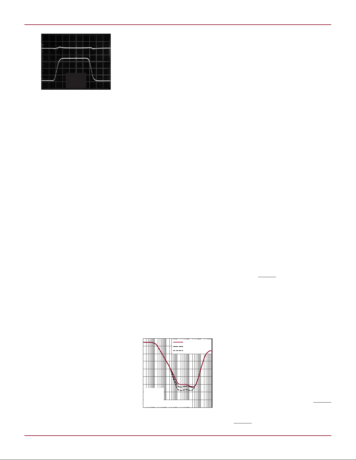
Figure 3. LT3050 transient response to load
dump condition (AC coupled)
minimal battery drain and drops to
<1µA in shutdown. The IC is housed
in a 12-lead 2mm × 3mm DFN and
12-lead thermally enhanced MSOP
packages, respectively, offering a
compact footprint.
Single IC Antenna Power
Supply with Protection and
Diagnostic Features
The 12V car battery, the starting
point for many active antenna voltage
supplies, is far from the quiet, stable
supply required by these systems. In
addition to noise, this 12V “supply” can
be subjected to reverse battery conditions or load dumps where the voltage
can range or spike anywhere from –36V
to 80V. The LT3050 protects both itself
and the antenna in this demanding
electrical environment, while providing
a stable, low noise output voltage. The
LT3050 also protects active antenna
supply circuitry in the event of a short
circuit within the antenna supply itself
with an accurate and programmable
current limit. Thermal conditions in
automotive environments are equally
challenging, requiring the supply to be
stable over a –40 to 125°C temperature
range with robust overtemperature
protection.
In addition to these difficult protection requirements, the LT3050
simplifies the gathering of diagnostic
information required to report antenna
status. Programmable open circuit
detection monitors the antenna supply current in case it should drop
below a specified minimum operating
condition. Programmable short circuit
detection monitors the antenna supply current in case it should exceed
a defined maximum and protects the
antenna, and its supply, by limiting
Linear Technology Magazine • December 2009
current flow. In addition, an analog
current monitor creates a signal
proportional to the antenna supply
current. This is handy as a diagnostic
input, or for signaling the system as to
which antenna type is mounted.
Protection Features in an Accurate,
Stable and Quiet Power Supply
The LT3050 generates a stable and
low noise supply for active antenna
systems, isolating and protecting the
antenna system from the car’s noisy
and volatile 12V supply. The IC can
withstand input voltages of ±50V and
reverse battery conditions potentially
generated from the 12V supply as
well as output reversals to ±50V (see
Figure 3).
The LT3050 provides excellent
power supply noise rejection, effectively isolating the antenna supply
from noise on the 12V supply line or
from an intermediate step-down regulator (see Figure 4). A single capacitor
provides both reference soft-start and
noise bypass, enabling a programmable start-up time and ultralow
noise operation.
A precision programmable current
limit provides additional protection by
allowing the user to set current limit
as low as 110% of maximum load,
without affecting load regulation during normal operation. In addition, the
combination of a backup current limit,
current limit fold-back, and robust
thermal shutdown with hysteresis
allow for indefinite output shorts from
a 50V input supply without damaging
the IC. The output can be pulled 50V
above the input with minimal cur-
Figure 4. LT3050 ripple rejection
rent flow into the input and without
damaging the IC.
Diagnostic Capabilities
The LT3050 provides diagnostic information to the car’s control systems.
An open-collector fault indicator,
capable of sinking 100µA, asserts if
open-circuit or short-circuit conditions are detected, or if the IC enters
thermal shutdown. The LT3050 also
features an integrated current monitor
that sources (via the I
pin) about
MON
1/100 of the output current for use
in antenna system monitoring and
protection. See the block diagram in
Figure 5. Simply connecting a resistor
from I
to GND creates a ground-
MON
referenced voltage proportional to
output current.
Programmable short-circuit detection and current limit is provided at
the I
pin and once set, varies less
MAX
than 5% over line and temperature.
The I
pin is the collector of a spe-
MAX
cially designed current mirror device
that sources about 1/200 of output
current. This pin is also the input to
the precision current limit amplifier.
Connecting a resistor (R
I
and GND sets the short-circuit
MAX
I(MAX)
) between
detection and programmable cur rent limit thresholds. The current
limit amplifier circuitry performs two
functions. First, it asserts the opencollector FAULT pin logic if the I
MAX
pin voltage reaches 600mV. Second,
it regulates the output drive current
such that the I
pin voltage does not
MAX
exceed 600mV, thus limiting the output current to 0.6V • 200/R
I(MAX)
.
The programmable open-circuit
detection threshold is provided at the
I
pin. The I
MIN
pin is the collector
MIN
of a specially designed current mirror
device that sources about 1/200 of
output current. This pin is also the
input to the open-circuit detection
comparator, referenced to the 600mV
internal reference. Connecting a resistor between I
and GND sets the
MIN
open-circuit detection threshold. If
the I
pin voltage falls below 600mV,
MIN
the comparator trips and the FAULT
pin asserts. The comparator uses a
small amount of hysteresis to prevent
FAULT pin glitches.
27

L DESIGN FEATURES
+
–
+
–
+
–
4
9
11
12
2
3
1
IN
5, 6
R1
D1
Q3
QI
MIN
1/200
QI
MON
1/100
QI
MAX
1/200
QPOWER
1
I
MAX
I
MIN
FAULT
I
MON
QFAULT
U1
GND
10, 13
REF/BYP
SHDN
ADJ
30k
R4
IDEAL DIODE
D3
Q2
D2
ERROR
AMPLIFIER
THERMAL/
CURRENT LIMITS
CURRENT
LIMIT
AMPLIFIER
100k
R3
I
MIN
COMPARATOR
100k
R2
600mV
REFERENCE
OUT
7, 8
+
–
1µF
12V
V
IN
IN
I
MON
I
MAX
I
MIN
FAULT
SHDN
GND
OUT
ADJ
REF/BYP
LT3050
5V
2.2µF
0.1µF
10nF
1%
442k
1%
60.4k
3k
(ADC FULL SCALE = 3V)
TO µP ADC
0.1µF
11.3k
(THRESHOLD = 10mA)
10nF
1.15k
(THRESHOLD = 100mA)
120k
Figure 6 shows a typical LT3050
application circuit set up as an active
antenna supply. Current limit, opencircuit fault threshold values, output
voltage, etc. were chosen arbitrarily for
illustrative purposes. In this example,
the open circuit detection threshold
is set by the 11.3k I
10mA. The 1.15k I
resistor to
MIN
resistor sets
MAX
the short circuit fault threshold and
current limit to 100mA (a 10nF I
MAX
capacitor is required for current limit
amplifier stability). The 3k I
MON
resistor provides a full-scale 3V signal when
output current equals 100mA. The
10nF REF/BYP capacitor provides a
28
Figure 5. LT3050 block diagram
5.5ms soft-start time and low noise
operation.
Conclusion
As car infotainment components have
grown more complex, the number of
active antenna systems has grown as
well. Sensitive circuitry in these active
antenna systems requires protection
and isolation from the harsh automotive environment as well as diagnostic
feedback to report antenna status.
and diagnostics linear regulator addresses active antenna design issues
with features such as programmable
Figure 6. LT3050 active antenna supply circuit
The LT3050 active antenna supply
current limit, soft-start, open-circuit
detection, output current monitor,
and an open-collector fault signal.
The LT3050 also features a wide input
voltage range, low quiescent current,
low output noise over a wide bandwidth, high output voltage accuracy,
low dropout voltage and ability to
withstand input and output voltage
reversal.
The LT3050’s stability and low
noise output benefits the end user as
well, with clearer and more reliable
antenna transmission/receive signals
to enhance the modern automotive
infotainment experience.
Linear Technology Magazine • December 2009
L
 Loading...