

Linear Technology LT1009CH, LT1009S8, LT1009IZ, LT1009IS8, LT1009CZ Datasheet
...
FEATURES
LT1009 Series
2.5V Reference
U
DESCRIPTIO
■
Maximum Initial Tolerance: 0.2%
■
Guaranteed
■
Maximum 0.6Ω Dynamic Impedance
■
Wide Operating Current Range
■
Directly Interchangeable with LM136 for Improved
Temperature Stability
Performance
■
No Adjustments Needed for Minimum Temperature
Coefficient
U
APPLICATIO S
■
Reference for 5V Systems
■
8-Bit A/D and D/A Reference
■
Digital Voltmeters
■
Current Loop Measurement and Control Systems
■
Power Supply Monitor
U
TYPICAL APPLICATION
The LT®1009 is a precision trimmed 2.5V shunt regulator
diode featuring a maximum initial tolerance of only ±5mV.
The low dynamic impedance and wide operating current
range enhances its versatility. The 0.2% reference tolerance is achieved by on-chip trimming which not only
minimizes the initial voltage tolerance but also minimizes
the temperature drift.
Even though no adjustments are needed with the LT1009,
a third terminal allows the reference voltage to be adjusted
±5% to calibrate out system errors. In many applications,
the LT1009 can be used as a pin-to-pin replacement of the
LM136 and the external trim network eliminated.
For a lower drift 2.5V reference, see the LT1019 data sheet.
, LTC and LT are registered trademarks of Linear Technology Corporation.
2.5V Reference
5V TO 35V
3.6k
LT1009
*DOES NOT AFFECT
TEMPERATURE COEFFICIENT.
±5% TRIM RANGE
10k*
TRIM
OUTPUT
1009 TA01
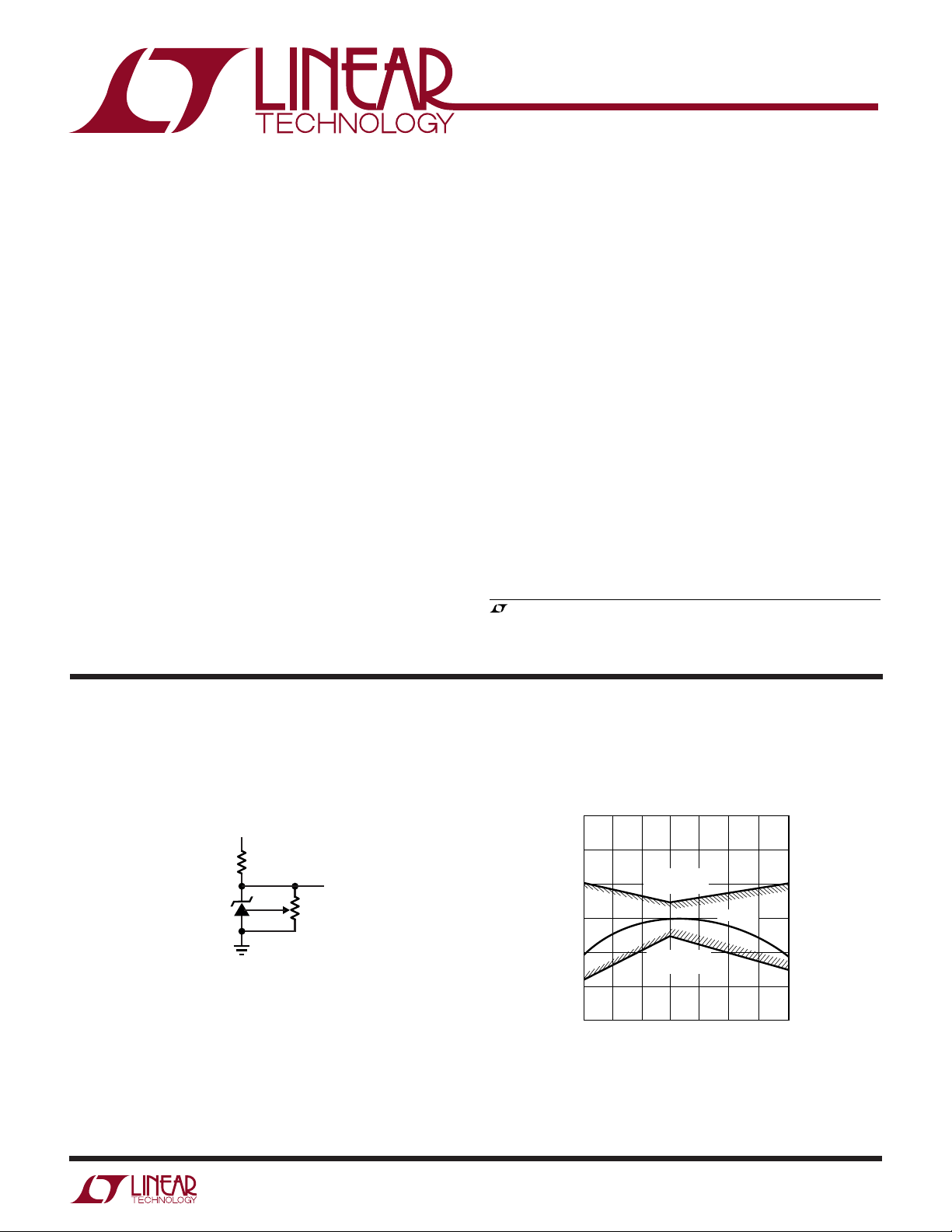
Output Voltage
2.53
2.52
–25 0
GUARANTEED
MAXIMUM
GUARANTEED
TEMPERATURE (°C)
2.51
2.50
2.49
REFERENCE VOLTAGE (V)
2.48
2.47
–50
MINIMUM
50 100 125
25 75
TYPICAL
1009 TA02
1
LT1009 Series
WWWU
ABSOLUTE AXI U RATI GS
(Note 1)
Reverse Current.................................................... 20mA
Forward Current ................................................... 10mA
Storage Temperature Range ................. –65°C to 150°C
Lead Temperature (Soldering, 10 sec).................. 300°C
UU
W
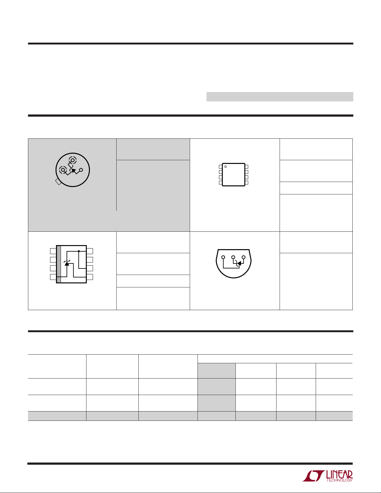
PACKAGE/ORDER I FOR ATIO
BOTTOM VIEW
+
ADJ
–
H PACKAGE
3-LEAD TO-46 METAL CAN
T
= 150°C, θJA = 440°C/ W, θJC = 80°C/W
JMAX
OBSOLETE PACKAGE
Consider the MS8, S8 or Z Packages for Alternate Source
TOP VIEW
1
NC
NC
2
NC
3
(–)
4
S8 PACKAGE
8-LEAD PLASTIC SO
T
= 150°C, θJA = 190°C/W
JMAX
8
(+)
7
NC
6
(+)
5
ADJ
ORDER PART
NUMBER
LT1009MH
LT1009CH
ORDER PART
NUMBER
LT1009S8
LT1009IS8
S8 PART MARKING
1009
1009I
Operating Temperature Range
LT1009/LT1009C .................................. 0°C to 70°C
LT1009I........................................... – 40°C to 85°C
LT1009M (OBSOLETE)................... –55°C to 125°C
ORDER PART
TOP VIEW
NC
1
NC
2
NC
3
(–)
4
MS8 PACKAGE
8-LEAD PLASTIC MSOP
T
= 150°C, θJA = 250°C/W
JMAX
BOTTOM VIEW
+
ADJ
8
(+)
7
NC
6
(+)
5
ADJ
–
NUMBER
LT1009CMS8
MS8 PART MARKING
LTQZ
ORDER PART
NUMBER
LT1009CZ
LT1009IZ
Z PACKAGE
3-LEAD PLASTIC TO-92
T
= 100°C, θJA = 160°C/ W
JMAX
Consult LTC Marketing for parts specified with wider operating temperature ranges.
U
AVAILABLE OPTIO S
TEMPERATURE
ACCURACY COEFFICIENT
TEMPERATURE
0°C to 70°C 0.20 25 LT1009CH LT1009CZ
–40°C to 85°C 0.20 35 LT1009IZ
–55°C to 125°C 0.20 35 LT1009MH
(%) (ppm/°C) OBSOLETE (MS8) (S8) (Z)
0.40 25 LT1009CMS8 LT1009S8
0.40 35 LT1009IS8
PACKAGE STYLE
TO-46 (H) MSOP-8 SO-8 TO-92
2
LT1009 Series
ELECTRICAL CHARACTERISTICS
The ● denotes specifications which apply over the full operating temperature range, otherwise specifications are TA = 25°C.
LT1009M LT1009I LT1009/LT1009C
SYMBOL PARAMETER CONDITIONS MIN TYP MAX MIN TYP MAX MIN TYP MAX UNITS
V
Z
∆V
∆I
r
Z
∆V
∆Temp Coefficient (Notes 2, 3) – 40°C ≤ T
∆V
∆Time
Reverse Breakdown TA = 25°C, IR = 1mA, H, Z Pkg 2.495 2.500 2.505 2.495 2.500 2.505 2.495 2.500 2.505 V
Voltage MS, S Pkg 2.49 2.50 2.51 2.49 2.50 2.51 V
Reverse Breakdown 400µA ≤ IR ≤ 10mA 2.6 6 2.6 10 2.6 10 mV
Z
Change with Current ● 3.0 10 3.0 12 3.0 12 mV
R
Reverse Dynamic IR = 1mA 0.2 0.6 0.2 1.0 0.2 1.0 Ω
Impedance
Temperature Stability T
Average Temperature 0°C ≤ TA ≤ 70°C 15 25 15 25 15 25 ppm/°C
Z
Long-Term Stability TA = 25°C ±0.1°C, IR = 1mA 20 20 20 ppm/kHr
Z
≤ TA ≤ T
MIN
–55°C ≤ T
MAX
≤ 85°C 35 ppm/°C
A
≤ 125°C 25 35 ppm/°C
A
● 0.4 1.0 0.4 1.4 0.4 1.4 Ω
● 15 15 1.8 4 mV
Note 1: Absolute Maximum Ratings are those values beyond which the life
of a device may be impaired.
Note 3: Average temperature coefficient is defined as the total voltage
change divided by the specified temperature change.
Note 2: Guaranteed by Design.
UW
TYPICAL PERFOR A CE CHARACTERISTICS
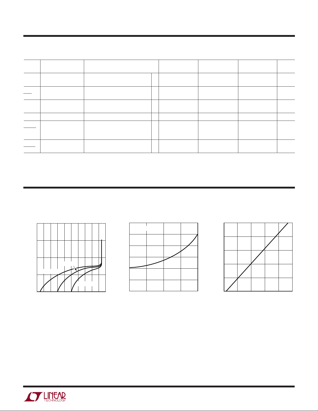
Reverse Characteristics
–1
10
–2
10
–3
10
TJ = 25°C
TJ = 125°C
–4
REVERSE CURRENT (A)
10
–5
10
0.5
1.0
REVERSE VOLTAGE (V)
1.4
TJ = –55°C
1.8
2.2
2.6
1009 G01
Forward Characteristics
1.2
TJ = 25°C
1.0
0.8
0.6
0.4
FORWARD VOLTAGE (V)
0.2
0
0.001
0.01 0.1 1 10
FORWARD CURRENT (mA)
1009 G02
Reverse Voltage Change
5
4
3
2
1
REVERSE VOLTAGE CHANGE (mV)
0
4
0
8
REVERSE CURRENT (mA)
12
16
20
1009 G03
3
 Loading...